Embed Size (px)
Citation preview
REFERENCE MANUAL HVAC/MECHANICAL
Ditributing systems
Energy Performance Integration in Corporate Public Real Estate Management
Report Number: EC Contract: EIE/07/129/S12.467632 www.epi-crem.org
Title of contact:
René Leeuw Ministry of VROM, RGD The Hague, the Netherlands Telephone: + 31 (0) 70 339 17 77 Email: [email protected]
EPI-CREM Frames of References [7-6-2010] [WP-4 and WP-5} 2 of 19
REFERENCE DESCRIPTION
Author/s
René Leeuw Ministry of VROM, RGD The Hague, the Netherlands Telephone: + 31 70 339 17 77 Email: [email protected]
Olaf Ooijevaar BuildDesk Arnhem, the Netherlands Telephone: +31 26 3537272 Email: [email protected] Chantal Tiekstra BuildDesk Arnhem, the Netherlands Telephone: +31 26 3537272 Email: [email protected] Editor
[Name] [Company/organisation name] [City, Country] Telephone: [+00-000000 ] Email: [email address]
Date:
June, 24th 2009
Report Number:
[number] EC Contract
EIE/07/129/S12.467632
www.epi-crem.org Project co-ordinator
Ministry of VROM (RGD), The Hague, The Netherlands Mr. René Leeuw [email protected]
Disclaimer The sole responsibility for the content of this publication lies with the authors. It does not represent the opinion of the Community. The authors and the European Commission are not responsible for any use that may be made of the information contained therein.
EPI-CREM Frames of References [7-6-2010] [WP-4 and WP-5} 3 of 19
Contents
1 Frames of reference of distributing systems ......................................................................................................... 4
1.1 Pipework for heating, cooling, compressed, air, vacuum, water, drains, fuel, ducts for ventilation- and air-conditioning, etc 4 1.1.1 Hierarchical classification 4
1.2 Specification distribution 4 1.2.1 function 4 1.2.2 Appliances and systems 6 1.2.3 Materials 7 1.2.4 Distributing 8
1.3 Registration method 9 1.3.1 Rules of thumb for determining the length of frequently occuring pipework 9 1.3.2 Piping lengths to heat emission systems 11
1.4 Relevant inspection points 12
1.5 Theoretical technical life cycle 12
1.6 Normalised classification description 12 1.6.1 classification 1: excellent 12 1.6.2 classification 2: good 13 1.6.3 classification 3: reasonable 14 1.6.4 classification 4: mediocre 15 1.6.5 classification 5: insufficient 15
2 Project Description ................................................................................................................................................ 18
Project Partners ............................................................................................................................................................. 19
EPI-CREM Frames of References [7-6-2010] [WP-4 and WP-5} 4 of 19
1 Frames of reference of distributing systems
1.1 Pipework for heating, cooling, compressed, air, vacuum, water, drains, fuel, ducts for ventilation- and air-conditioning, etc
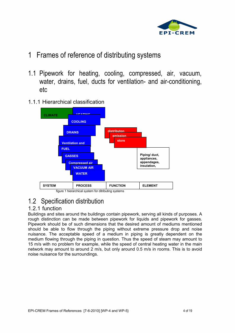
1.1.1 Hierarchical classification
figure 1 hierarchical system for ditributing systems
1.2 Specification distribution 1.2.1 function Buildings and sites around the buildings contain pipework, serving all kinds of purposes. A rough distinction can be made between pipework for liquids and pipework for gasses. Pipework should be of such dimensions that the desired amount of mediums mentioned should be able to flow through the piping without extreme pressure drop and noise nuisance. The acceptable speed of a medium in piping is greatly dependent on the medium flowing through the piping in question. Thus the speed of steam may amount to 15 m/s with no problem for example, while the speed of central heating water in the main network may amount to around 2 m/s, but only around 0.5 m/s in rooms. This is to avoid noise nuisance for the surroundings.
distributon
CLIMATE MECHANICAL
HEATING
Piping/ duct, appliances, appendages, insulation, brackets, fitting suspension
COOLING
DRAINS
Ventilation and Air conditioning FUEL
GASSES
Compressed air
VACUUM AIR
WATER
emission
store
SYSTEM PROCESS FUNCTION ELEMENT
EPI-CREM Frames of References [7-6-2010] [WP-4 and WP-5} 5 of 19
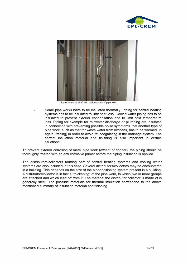
figure 2 service shaft with various sorts of pipe work
- Some pipe works have to be insulated thermally. Piping for central heating
systems has to be insulated to limit heat loss. Cooled water piping has to be insulated to prevent exterior condensation and to limit cold temperature loss. Piping for example for rainwater discharge or plumbing are insulated in connection with preventing possible noise symptoms. Yet another type of pipe work, such as that for waste water from kitchens, has to be warmed up again (tracing) in order to avoid fat coagulating in the drainage system. The correct insulation material and finishing is also important in certain situations.
To prevent exterior corrosion of metal pipe work (except of copper), the piping should be thoroughly treated with an anti corrosive primer before the piping insulation is applied.
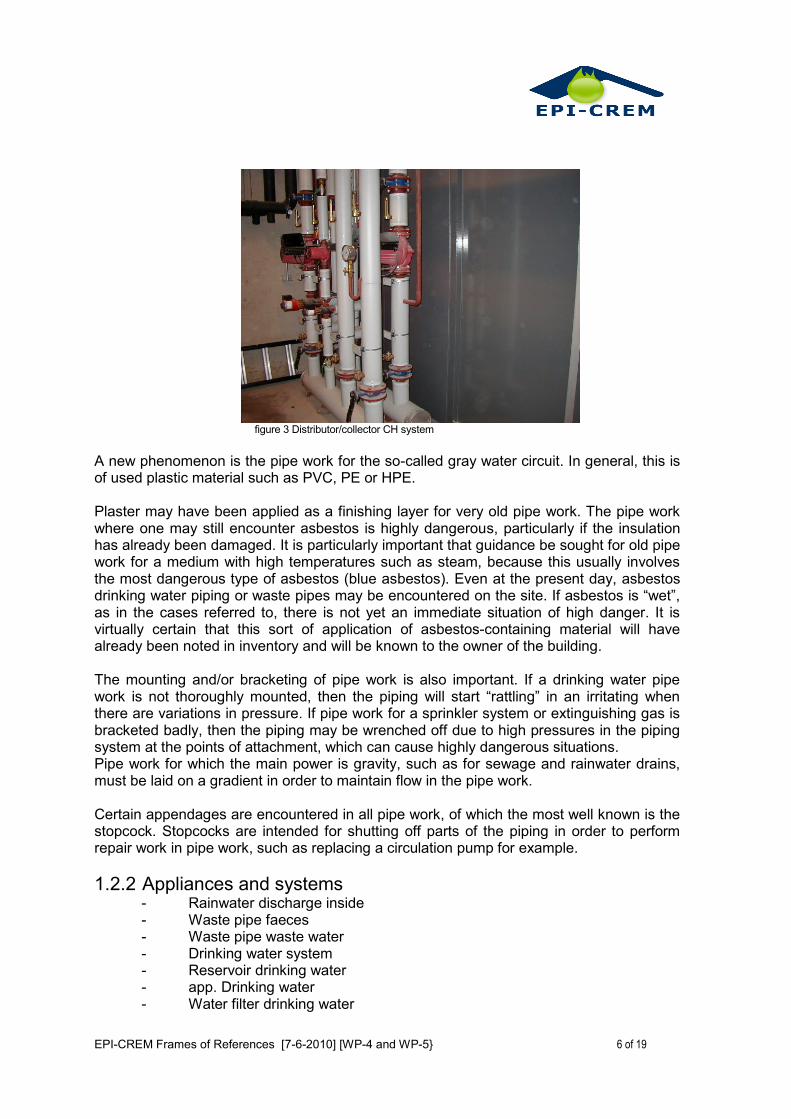
The distributors/collectors forming part of central heating systems and cooling water systems are also included in this case. Several distributors/collectors may be encountered in a building. This depends on the size of the air-conditioning system present in a building. A distributor/collector is in fact a “thickening” of the pipe work, to which two or more groups are attached and which lead off from it. The material the distributor/collector is made of is generally steel. The possible materials for thermal insulation correspond to the above mentioned summary of insulation material and finishing.
EPI-CREM Frames of References [7-6-2010] [WP-4 and WP-5} 6 of 19
figure 3 Distributor/collector CH system
A new phenomenon is the pipe work for the so-called gray water circuit. In general, this is of used plastic material such as PVC, PE or HPE.
Plaster may have been applied as a finishing layer for very old pipe work. The pipe work where one may still encounter asbestos is highly dangerous, particularly if the insulation has already been damaged. It is particularly important that guidance be sought for old pipe work for a medium with high temperatures such as steam, because this usually involves the most dangerous type of asbestos (blue asbestos). Even at the present day, asbestos drinking water piping or waste pipes may be encountered on the site. If asbestos is “wet”, as in the cases referred to, there is not yet an immediate situation of high danger. It is virtually certain that this sort of application of asbestos-containing material will have already been noted in inventory and will be known to the owner of the building.
The mounting and/or bracketing of pipe work is also important. If a drinking water pipe work is not thoroughly mounted, then the piping will start “rattling” in an irritating when there are variations in pressure. If pipe work for a sprinkler system or extinguishing gas is bracketed badly, then the piping may be wrenched off due to high pressures in the piping system at the points of attachment, which can cause highly dangerous situations. Pipe work for which the main power is gravity, such as for sewage and rainwater drains, must be laid on a gradient in order to maintain flow in the pipe work.
Certain appendages are encountered in all pipe work, of which the most well known is the stopcock. Stopcocks are intended for shutting off parts of the piping in order to perform repair work in pipe work, such as replacing a circulation pump for example.
1.2.2 Appliances and systems - Rainwater discharge inside - Waste pipe faeces - Waste pipe waste water - Drinking water system - Reservoir drinking water - app. Drinking water - Water filter drinking water
EPI-CREM Frames of References [7-6-2010] [WP-4 and WP-5} 7 of 19
- Warm tap water system - Industrial water system - Special appendages industrial water - Condensation recycling system - Pipe work water treatment - Gas pipe work fuel - Compressed air system - Pipe work + appendages vacuum - System medical gasses - System technical gasses - System special gasses - Cooling tower - Refrigerant - Cold distribution - Distributor/collector - Special appendages - Warm or hot water system - Pipe work + app. and insulation steam - Local fire extinguishing appliances - Extinguishing gas system - Sprinkler system - Central vacuum cleaning system - Site piping + and fittings - Site piping central heating. - Site piping fire hydrants
1.2.3 Materials The choice of materials and the organisation of a pipe work are adapted to the specific objectives for which the pipe work was installed. Below, a broad overview is reproduced of the materials used for specific pipe works or which may be encountered. 13.2.3.1 Drains
- cast iron (antiquated by now) - plastic such as PVC, PE and HPE - glass (laboratories) - ABS tubes - cast iron piping - zinc-coated steel piping
13.2.3.2 Water
- copper (lead piping in drinking water systems may no longer be used) - steel with and without internal coating - spheroidal cast iron - precision pipe - plastic piping
1.2.3.3 Gasses
- steel (jointless and threaded pipe) - stainless steel - copper - spheroidal and gray cast iron - PVC and CPE (natural gas)
EPI-CREM Frames of References [7-6-2010] [WP-4 and WP-5} 8 of 19
- Zinc-coated steel
1.2.3.4 The insulating and finishing materials occurring most frequently are:
- PUR and acketed in Isogenopak or aluminium scales, in the case of pipework filled with warm or hot water
- Mineral wool jacketted in aluminium foil, in the case of pipework for central heating systems
- Mineral wool jacketted in aluminium scales, in the case of hot water or steam pipework
- Vapour proof insulation (type Armaflex) for cold and cooled water. Pipework that is installed in the open air are jacketted with aluminium scales to prevent water entering.
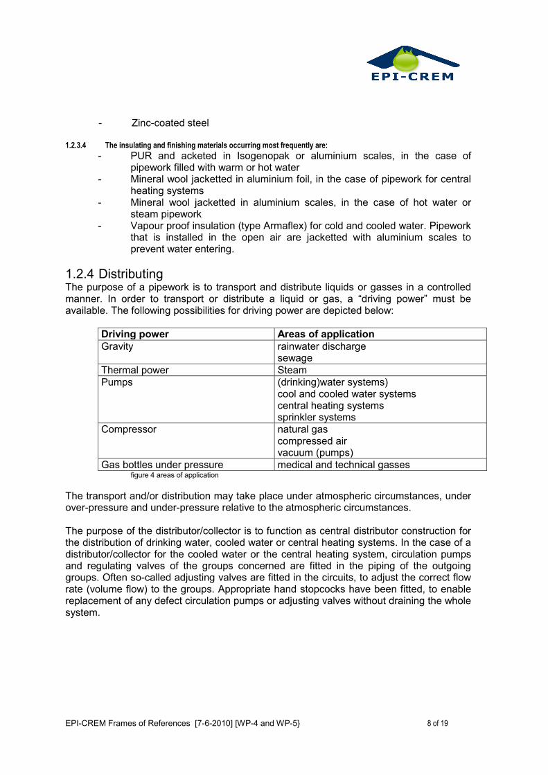
1.2.4 Distributing The purpose of a pipework is to transport and distribute liquids or gasses in a controlled manner. In order to transport or distribute a liquid or gas, a “driving power” must be available. The following possibilities for driving power are depicted below:
Driving power Areas of application
Gravity rainwater discharge sewage
Thermal power Steam
Pumps (drinking)water systems) cool and cooled water systems central heating systems sprinkler systems
Compressor natural gas compressed air vacuum (pumps)
Gas bottles under pressure medical and technical gasses figure 4 areas of application
The transport and/or distribution may take place under atmospheric circumstances, under over-pressure and under-pressure relative to the atmospheric circumstances. The purpose of the distributor/collector is to function as central distributor construction for the distribution of drinking water, cooled water or central heating systems. In the case of a distributor/collector for the cooled water or the central heating system, circulation pumps and regulating valves of the groups concerned are fitted in the piping of the outgoing groups. Often so-called adjusting valves are fitted in the circuits, to adjust the correct flow rate (volume flow) to the groups. Appropriate hand stopcocks have been fitted, to enable replacement of any defect circulation pumps or adjusting valves without draining the whole system.
EPI-CREM Frames of References [7-6-2010] [WP-4 and WP-5} 9 of 19
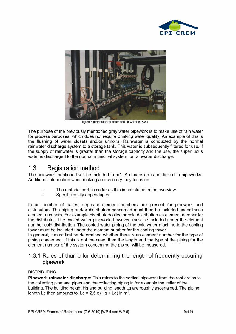
figure 5 distributor/collector cooled water (GKW)
The purpose of the previously mentioned gray water pipework is to make use of rain water for process purposes, which does not require drinking water quality. An example of this is the flushing of water closets and/or urinoirs. Rainwater is conducted by the normal rainwater discharge system to a storage tank. This water is subsequently filtered for use. If the supply of rainwater is greater than the storage capacity and the use, the superfluous water is discharged to the normal municipal system for rainwater discharge.
1.3 Registration method The pipework mentioned will be included in m1. A dimension is not linked to pipeworks. Additional information when making an inventory may focus on
- The material sort, in so far as this is not stated in the overview - Specific costly appendages
In an number of cases, separate element numbers are present for pipework and distributors. The piping and/or distributors concerned must then be included under these element numbers. For example distributor/collector cold distribution as element number for the distributor. The cooled water pipework, however, must be included under the element number cold distribution. The cooled water piping of the cold water machine to the cooling tower must be included under the element number for the cooling tower. In general, it must first be determined whether there is an element number for the type of piping concerned. If this is not the case, then the length and the type of the piping for the element number of the system concerning the piping, will be measured.
1.3.1 Rules of thumb for determining the length of frequently occuring pipework
DISTRIBUTING
Pipework rainwater discharge: This refers to the vertical pipework from the roof drains to the collecting pipe and pipes and the collecting piping in for example the cellar of the building. The building height Hg and building length Lg are roughly ascertained. The piping length Le then amounts to: Le = 2.5 x (Hg + Lg) in m1.
EPI-CREM Frames of References [7-6-2010] [WP-4 and WP-5} 10 of 19
Sanitary pipework+: Referred to is the vertical pipework from the toilet group on the highest storey to the collector pipe or pipes in the cellar, for example. The building height Hg n the building length Lg is roughly ascertained. The number of centres in which the wet groups Nn are installed, are subsequently counted. The piping length Le then amounts to: Le = Lg + 2.5 x Nn x Hg in m1.
Pipework drinking water and warm tap water: Referred to is the horizontal and vertical pipework for the distribution of hot or cold water in the building. The building height Hg and the building length Lg are roughly ascertained. The number of centres in which the wet groups Nn are installed are subsequently counted. The piping length amounts to: Le = Lg + 2.5 x Nn x Hg in ml. The above calculation is valid both for drinking water and hot tap water. Pipework and industrial water: The building height is measured (Lv) to the point where the highest off-take point is installed. The horizontal length (Lh) is subsequently measured from the interrupt system or water softening system in the building to the off-take point furthest away. The piping length Le then amounts to: Le = 3 x (lv + Lh). Pipework condensation: Referred to is the horizontal and vertical pipework for the recycling of condensation to a central point in the building, complete with the condensation pump and collection tank. The building height is measured (Lv) to the point at which the highest off-take point is installed. The building length Lg is subsequently ascertained. The piping length Le then amounts to: Le = 4 x (lv + Lh). Pipework fuel: The sum in ml of the horizontal distance (Lh) and the vertical distance (Lv) is measured between the point of entry in the building and the central heating boilerIn laboratoriums, the horizontal distance (Lh) and the vertical distance (Lv) is measured between the point of entry in the building and the off-take point furthest away in, for example, a fume cupboard. The sum of Lh+Lv in m1 is multiplied per storey by a factor 2.5. Pipework compressed air and vacuum: Referred to is the pipework between the pressuriser or vacuum tank and the off-take points. Not referred to, is the pipework for a pneumatic regulator system. The horizontal distance Lh is measured and the vertical distance Lv between the air compressor or vacuum pump and the off-take point furthest away. The sum of Lh+Lv in ml must be multiplied by the factor 2.5. Technical and medical gasses: The horizontal distance Lh and the vertical distance Lv is measured per gas sort between the bottle battery and the off-take point furthest away. The sum of Lh + Lv in m' must be multiplied by the factor 15. Pipework cooling water: Referred to is the pipework between the cooling unit and the cooling tower, including stopcocks. The length of the pipework is broadly ascertained. In some cases the cooling unit is located in the cellar and the cooling tower on the roof. The “length” then amounts to 2.5 x the building height. Pipework cooled water: Referred to is the total pipework from the cooling unit or units to the distributor/ collector and subsequently to the air-conditioning cabinets, aftercoolers and induction units. The equivalent piping length Le is ascertained that can arise from the sum of
EPI-CREM Frames of References [7-6-2010] [WP-4 and WP-5} 11 of 19
several types of pipework. See the pipework below for this. The diameter of the piping is processed in the “formulas” below into a set cost index number by means of an adjustment factor.
Total piping length cooled water: The total piping length is the sum of the pipework present in the building
Pipework central heating system: The equivalent piping length Le that may arise from the sum of several types of pipework is ascertained. See the pipework below for this. The diameter of the piping is processed in the “formulas” below into a set cost index number by means of an adjustment factor.
Total piping length c.v.- water: The total piping length is the sum of the pipework present in the building
Piping length to air/conditioning cabinets: The horizontal distance (Lh) and the vertical distance (Lv) is ascertained between the air-conditioning cabinet furthest away relative to the cooling unit or units. The total piping length Le in m1 then amounts: 2.6 x (Lh + Lv) in m1.
1.3.2 Piping lengths to heat emission systems Induction units: The number of storeys Nv is counted. The length L and the depth D of the building are roughly ascertained. The "perimeter length" Lo = 2x(L+D) m1. The total length Le of the pipework amounts to: Le = 2.6 x Nv x Lo in m1. Everything is included in the factor 2.6 such as 2 pipeworks for supply and return, curves and the transport piping. If a building consists of high and low rise buildings, then the procedure described for both kinds of buildings must be carried out. If the building has a so-called centre of which the façade likewise borders on the open air and on which induction units are likewise placed, then the total length of this specific pipework: Lespec. = 0.2 x 2.6 x Nv x Lo in ml.
Aftercoolers: For any aftercoolers that are fitted in the air channel system, the piping length amounts to: Lenak. = 2 x the building length.
Radiators/convectors: The number of storeys Nv is counted. The length L and the depth D of the building is roughly ascertained. The "perimeter length" Lo = 2x(L+D) m1. The total length Le of the pipework amounts to: Le = 2.6 x Nv x Lo in m1. All factors are included in the factor 26 such as 2 pipeworks for supply and return, curves and the transport piping. If a building consists of high and low rise buildings, then the procedure described for both kinds of buildings must be carried out.
Radiation panels: If radiation panels have been installed in a specific part of the building but integrated into the heating system, then the "formula" is: Le = 2.7 x Nv x Lo in m1.
Induction units: The approach for specifying the total piping length Le is exactly the same with that for the radiators/convectors. If induction units have been installed in the building on the outer layer and radiators/convectors in the indoor part, then broadly Lo of the inside layer must be ascertained and the number of stories within which the radiators/convectors have been installed. The total piping length for these parts of the system then amounts to the sum of both pipeworks.
EPI-CREM Frames of References [7-6-2010] [WP-4 and WP-5} 12 of 19
Air-conditioning cabinets: The horizontal distance (Lh) and the vertical distance (Lv) between the air-conditioning cabinet furthest away from the boiler is ascertained. The total piping length Le in m1 then amounts to: 2.6 x (Lh + Lv) in m1
1.4 Relevant inspection points - hanging and bracketing - specific appendages - mechanical situation of the pipework - piping insulation - connections - dirt and/or fat accretion in channels - sealing measurement points in channels - correct and good closing of inspection hatches in channels
1.5 Theoretical technical life cycle The cycles below concerning life expectation apply:
Pipework metal and plastic 30 years Pipework condensation 10 years Pipework for water treatment metal 15 years Pipework for water treatment plastic 25 years Cooling water pipework metal 20 years Cooling water pipework plastic 25 years Pipework heat or cold storage in the ground 20 years
1.6 Normalised classification description 1.6.1 classification 1: excellent 1.6.1.1 Condition
Functional
The transport and the distribution of gasses and liquids does not undergo stagnation in any way at all. The piping flow is well dimensioned. There are no leaks encountered. Any necessary piping insulation is appropriate from the thermal and noise point of view. The vapour-proof aspect of the insulation is guaranteed. Obsolescence
The symptoms of obsolescence are restricted to dust deposit on the piping. Small scratches or surface damage may be encountered. Blockage of piping is not involved. Basic quality
The materials used are attuned to the gas or the liquid that flows through the piping. The piping insulation completely meets the purpose for which it is installed. The piping is installed if necessary at the correct gradient. Provision for bleeding and/or aeration is installed. The pipe laying is taut and the bracketing/mounting of the piping meets the demands required.
EPI-CREM Frames of References [7-6-2010] [WP-4 and WP-5} 13 of 19
1.6.1.2 Energy :
Heating ad distributing: Mixing regulating with 2-way regulating valves and revolutions regulated pumps in heating and cooling distribution systems Heating distribution T delivery <350C Cooling distribution T delivery >200C
1.6.2 classification 2: good 1.6.2.1 Condition :
Functional
A possible blockage may have occurred in drain piping in recent years. The origin of the blockage will generally be down to incorrect use of the pipework, such as due to vandalism or the transport of substances for which the piping is not designed. A small leak, particularly between connections, may have occurred without causing severe damage. The transport and the distribution by the piping are still guaranteed. Obsolescence
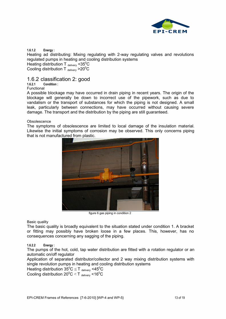
The symptoms of obsolescence are limited to local damage of the insulation material. Likewise the initial symptoms of corrosion may be observed. This only concerns piping that is not manufactured from plastic.
figure 6 gas piping in condition 2
Basic quality
The basic quality is broadly equivalent to the situation stated under condition 1. A bracket or fitting may possibly have broken loose in a few places. This, however, has no consequences concerning any sagging of the piping. 1.6.2.2 Energy :
The pumps of the hot, cold, tap water distribution are fitted with a rotation regulator or an automatic on/off regulator Application of separated distributor/collector and 2 way mixing distribution systems with single revolution pumps in heating and cooling distribution systems
Heating distribution 350C T delivery <450C
Cooling distribution 200C T delivery <160C
EPI-CREM Frames of References [7-6-2010] [WP-4 and WP-5} 14 of 19
1.6.3 classification 3: reasonable 1.6.3.1 Condition :
Functional
The functionality of the pipework has been an issue several times. Due to defects such as a blockage, nuisance has arisen because of tempory closure of toilet groups. Leakage for screw or flanged joints may be observed. These leakages occur locally and do not determine the image of its functionality as a whole. Leakages in piping for gasses have not occurred. Obsolescence
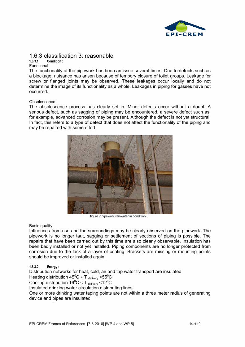
The obsolescence process has clearly set in. Minor defects occur without a doubt. A serious defect, such as sagging of piping may be encountered, a severe defect such as, for example, advanced corrosion may be present. Although the defect is not yet structural. In fact, this refers to a type of defect that does not affect the functionality of the piping and may be repaired with some effort.
figure 7 pipework rainwater in condition 3
Basic quality
Influences from use and the surroundings may be clearly observed on the pipework. The pipework is no longer taut, sagging or settlement of sections of piping is possible. The repairs that have been carried out by this time are also clearly observable. Insulation has been badly installed or not yet installed. Piping components are no longer protected from corrosion due to the lack of a layer of coating. Brackets are missing or mounting points should be improved or installed again. 1.6.3.2 Energy :
Distribution networks for heat, cold, air and tap water transport are insulated
Heating distribution 450C T delivery <550C
Cooling distribution 160C T delivery <120C Insulated drinking water circulation distributing lines One or more drinking water taping points are not within a three meter radius of generating device and pipes are insulated
EPI-CREM Frames of References [7-6-2010] [WP-4 and WP-5} 15 of 19
1.6.4 classification 4: mediocre 1.6.4.1 Condition :
Functional
Under the normal conditions of use, interruption to use has occurred with some regularity. This is often the result of blockages or leakage. Minor leakages in pipework for gasses may have also occurred. The repairs to the pipework in general are often carried out in a temporary way and are certainly not professional. Appendages are obsolescent based on time and actually should be replaced. Obsolescence
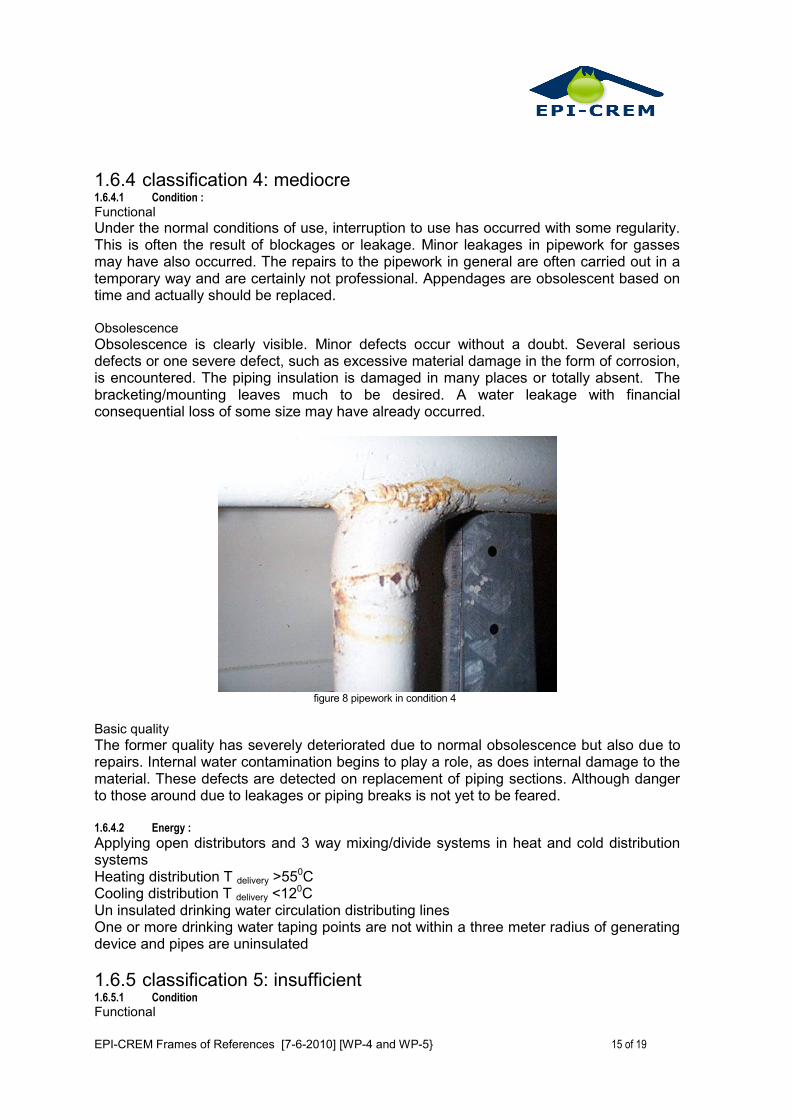
Obsolescence is clearly visible. Minor defects occur without a doubt. Several serious defects or one severe defect, such as excessive material damage in the form of corrosion, is encountered. The piping insulation is damaged in many places or totally absent. The bracketing/mounting leaves much to be desired. A water leakage with financial consequential loss of some size may have already occurred.
figure 8 pipework in condition 4
Basic quality
The former quality has severely deteriorated due to normal obsolescence but also due to repairs. Internal water contamination begins to play a role, as does internal damage to the material. These defects are detected on replacement of piping sections. Although danger to those around due to leakages or piping breaks is not yet to be feared. 1.6.4.2 Energy :
Applying open distributors and 3 way mixing/divide systems in heat and cold distribution systems Heating distribution T delivery >550C Cooling distribution T delivery <120C Un insulated drinking water circulation distributing lines One or more drinking water taping points are not within a three meter radius of generating device and pipes are uninsulated
1.6.5 classification 5: insufficient 1.6.5.1 Condition
Functional
EPI-CREM Frames of References [7-6-2010] [WP-4 and WP-5} 16 of 19
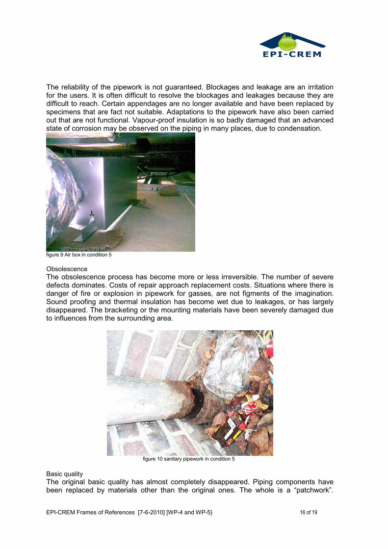
The reliability of the pipework is not guaranteed. Blockages and leakage are an irritation for the users. It is often difficult to resolve the blockages and leakages because they are difficult to reach. Certain appendages are no longer available and have been replaced by specimens that are fact not suitable. Adaptations to the pipework have also been carried out that are not functional. Vapour-proof insulation is so badly damaged that an advanced state of corrosion may be observed on the piping in many places, due to condensation.
figure 9 Air box in condition 5
Obsolescence
The obsolescence process has become more or less irreversible. The number of severe defects dominates. Costs of repair approach replacement costs. Situations where there is danger of fire or explosion in pipework for gasses, are not figments of the imagination. Sound proofing and thermal insulation has become wet due to leakages, or has largely disappeared. The bracketing or the mounting materials have been severely damaged due to influences from the surrounding area.
figure 10 sanitary pipework in condition 5
Basic quality
The original basic quality has almost completely disappeared. Piping components have been replaced by materials other than the original ones. The whole is a “patchwork”.
EPI-CREM Frames of References [7-6-2010] [WP-4 and WP-5} 17 of 19
Radical renovation or total replacement of the pipework within the short term is unavoidable. 1.6.5.2 Energy :
Uninsulated heat, cold and tap water distribution networks. No regulation Uninsulated drinking water circulation distribution lines
EPI-CREM Frames of References [7-6-2010] [WP-4 and WP-5} 18 of 19
2 Project Description
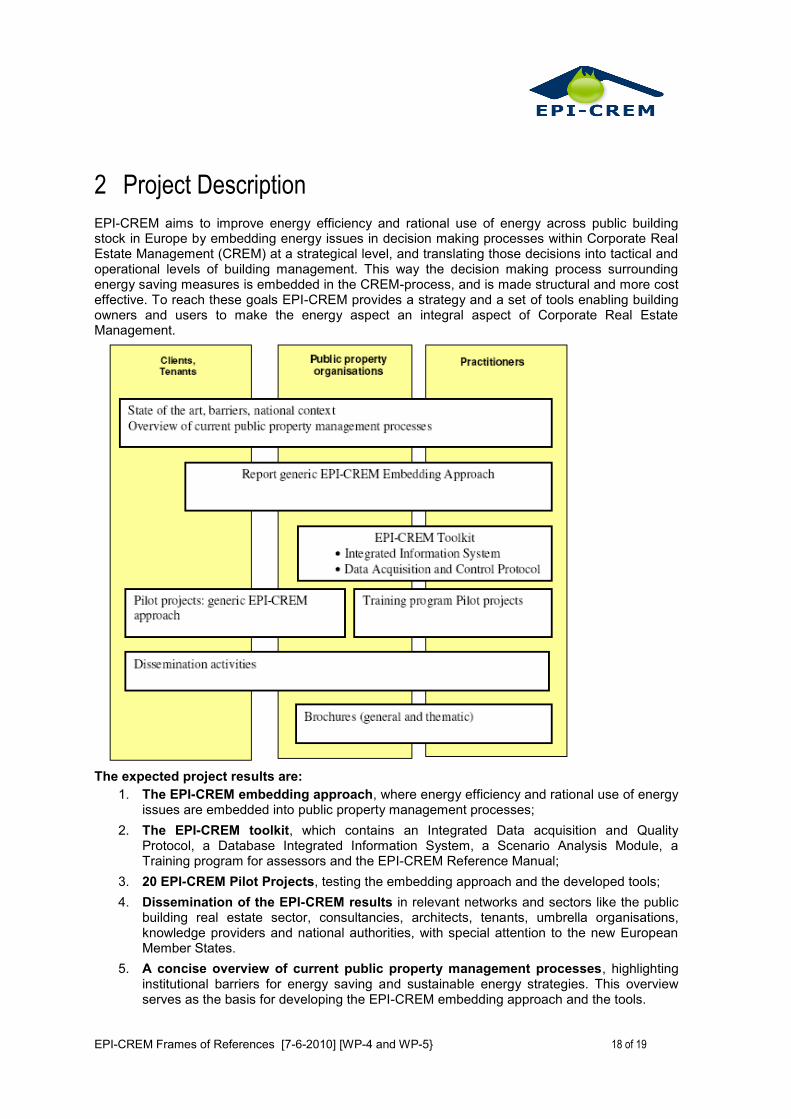
EPI-CREM aims to improve energy efficiency and rational use of energy across public building stock in Europe by embedding energy issues in decision making processes within Corporate Real Estate Management (CREM) at a strategical level, and translating those decisions into tactical and operational levels of building management. This way the decision making process surrounding energy saving measures is embedded in the CREM-process, and is made structural and more cost effective. To reach these goals EPI-CREM provides a strategy and a set of tools enabling building owners and users to make the energy aspect an integral aspect of Corporate Real Estate Management.
The expected project results are:
1. The EPI-CREM embedding approach, where energy efficiency and rational use of energy issues are embedded into public property management processes;
2. The EPI-CREM toolkit, which contains an Integrated Data acquisition and Quality Protocol, a Database Integrated Information System, a Scenario Analysis Module, a Training program for assessors and the EPI-CREM Reference Manual;
3. 20 EPI-CREM Pilot Projects, testing the embedding approach and the developed tools;
4. Dissemination of the EPI-CREM results in relevant networks and sectors like the public building real estate sector, consultancies, architects, tenants, umbrella organisations, knowledge providers and national authorities, with special attention to the new European Member States.
5. A concise overview of current public property management processes, highlighting institutional barriers for energy saving and sustainable energy strategies. This overview serves as the basis for developing the EPI-CREM embedding approach and the tools.
EPI-CREM Frames of References [7-6-2010] [WP-4 and WP-5} 19 of 19
Project Partners
Project Co-ordinator: The Ministry of VROM, Rijksgebouwendienst, The Netherlands
BuildDesk, The Netherlands
Austrian Energy Agency, Austria
Energie Bewusst Kärnten, Austria
Centre Scientifique et Technique du Bâtiment, France