Embed Size (px)
DESCRIPTION
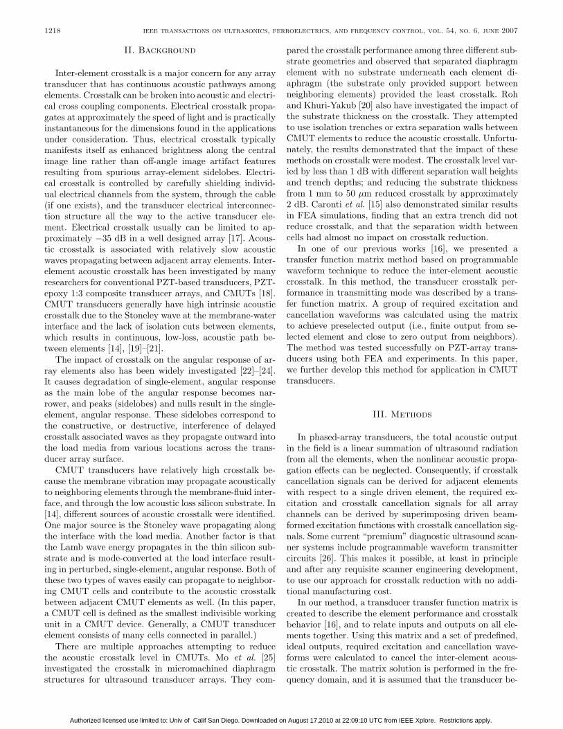
Manuscript received December 15, 2005; accepted January 8, 2007. This work was also supported in part by NIH NIBIB grants EB001826, EB002349 and DoD CDMRP W81XWH-04-1-0240. The authors are with the Department of Biomedical Engineer- ing, University of Virginia, Charlottesville, VA 22901 (e-mail: [email protected]). Digital Object Identifier 10.1109/TUFFC.2007.375 0885–3010/$25.00 c 2007 IEEE I. Introduction 1217
Citation preview
ieee transactions on ultrasonics, ferroelectrics, and frequency control, vol. 54, no. 6, june 2007 1217
Reducing Inter-Element Acoustic Crosstalk inCapacitive Micromachined Ultrasound
TransducersShiwei Zhou and John A. Hossack, Senior Member, IEEE
Abstract—The inter-element acoustic crosstalk prob-lem in capacitive micromachined ultrasound transducer(CMUT) arrays is discussed in this paper. A transfer func-tion matrix approach was used to derive modified trans-mit waveforms on adjacent elements to reduce the apparentacoustic crosstalk. The significance of this is that this tech-nique relies on programmable waveforms, so that it yields areduced crosstalk effect with no additional fabrication com-plexity if the requisite programmable waveform transmitcircuits are available. The crosstalk reduction achieved bythis method also was examined in combination with conven-tional (physical separation-based) crosstalk reduction ap-proaches.
A CMUT transducer array structure was simulated ina two-dimensional (2-D) model using finite element analy-sis (FEA), and the crosstalk reduction method was testedfor both small and large alternating current (AC) (ultra-sonic) excitation conditions. A 25 dB crosstalk reductionwas achieved for small AC excitation conditions in whichapproximately linear operation is encountered. When theAC excitation amplitude was large compared to the directcurrent (DC) bias, an “iterative harmonic cancellation” ap-proach (also based on programmable waveform techniques)could be applied in combination with the crosstalk reduc-tion method to minimize the inherently transmitted har-monics, and a similar crosstalk reduction effect of 25.5 dBwas achieved. This method also can be combined withother structure-modification based crosstalk reduction ap-proaches.
I. Introduction
Capacitive micromachined ultrasound transducers(CMUT) have attracted considerable attention re-
cently and have been proposed and tested for medicaldiagnostic applications because they offer several techni-cal and potential cost advantages with respect to conven-tional piezoelectric transducers [1], [2]. Research resultshave shown that CMUTs can achieve very broad frequencybandwidth [3], [4], resulting in improved image spatial res-olution. Some CMUT fabrication processes are compatiblewith complementary metal oxide semiconductor (CMOS)process, and thus it is possible to tightly integrate electron-ics and the CMUT over a common silicon substrate [5], [6].
Manuscript received December 15, 2005; accepted January 8,2007. This work was also supported in part by NIH NIBIB grantsEB001826, EB002349 and DoD CDMRP W81XWH-04-1-0240.
The authors are with the Department of Biomedical Engineer-ing, University of Virginia, Charlottesville, VA 22901 (e-mail:[email protected]).
Digital Object Identifier 10.1109/TUFFC.2007.375
Since CMUT transducers are manufactured using semi-conductor microlithography processes, the per-part cost islow when large volumes are fabricated. Moreover, the ef-fective acoustic impedance of the CMUT membrane is wellmatched to the impedance of water or tissue. These advan-tages provide CMUT technology the potential to replaceconventional PZT transducers, primarily in compact, highelement count one-dimensional (1-D) or 2-D arrays [2], [7],ultrasound transducers for intravascular ultrasound imag-ing [8].
However, CMUTs have some problems that may limittheir use in practical applications. One problem is thatthe overall device electromechanical conversion couplingis lower than a PZT transducer, unless the physical de-sign is highly optimized and the device is biased with adirect current (DC) voltage that brings the membraneclose to the collapse threshold [9], [10] (which increasesthe risk of membrane collapse). Also, a CMUT transduceroperates nonlinearly because the output electrostatic forceis approximately proportional to the square of the inputelectrical voltage, resulting in harmonic components in itstransmitted signals. This problem makes CMUTs unsuit-able for tissue harmonic imaging as it is impossible todistinguish harmonic signal generated by the human tis-sue from transmitted harmonic components. Several ap-proaches have been proposed to solve the harmonic gen-eration problem [11–13]. In our earlier work [11], we sim-ulated and experimentally verified that 18.6 dB reductionin second harmonic generation was easily attainable.
The problem discussed in this paper is that, when builtinto an array transducer, the silicon-based CMUT devicespotentially have significant acoustic crosstalk between ar-ray elements because the crosstalk may be coupled eas-ily through the transducer-medium interface as well asvia the silicon substrate [14], [15]. The silicon substrateis frequently single crystal and glass-like (i.e., very lowacoustic loss). In this paper, we apply a transfer functionmatrix method based on programmable waveform tech-nique to reduce the inter-element acoustic crosstalk [16].Finite element analysis (FEA) simulation results were ob-tained for both small and large AC excitation conditions.Other known crosstalk reduction methods are discussedas well for comparison purposes. These existing crosstalkreduction methods can be used in combination with thecrosstalk cancellation approach to yield further reductionsin net acoustic crosstalk.
0885–3010/$25.00 c© 2007 IEEE
Authorized licensed use limited to: Univ of Calif San Diego. Downloaded on August 17,2010 at 22:09:10 UTC from IEEE Xplore. Restrictions apply.
1218 ieee transactions on ultrasonics, ferroelectrics, and frequency control, vol. 54, no. 6, june 2007
II. Background
Inter-element crosstalk is a major concern for any arraytransducer that has continuous acoustic pathways amongelements. Crosstalk can be broken into acoustic and electri-cal cross coupling components. Electrical crosstalk propa-gates at approximately the speed of light and is practicallyinstantaneous for the dimensions found in the applicationsunder consideration. Thus, electrical crosstalk typicallymanifests itself as enhanced brightness along the centralimage line rather than off-angle image artifact featuresresulting from spurious array-element sidelobes. Electri-cal crosstalk is controlled by carefully shielding individ-ual electrical channels from the system, through the cable(if one exists), and the transducer electrical interconnec-tion structure all the way to the active transducer ele-ment. Electrical crosstalk usually can be limited to ap-proximately −35 dB in a well designed array [17]. Acous-tic crosstalk is associated with relatively slow acousticwaves propagating between adjacent array elements. Inter-element acoustic crosstalk has been investigated by manyresearchers for conventional PZT-based transducers, PZT-epoxy 1:3 composite transducer arrays, and CMUTs [18].CMUT transducers generally have high intrinsic acousticcrosstalk due to the Stoneley wave at the membrane-waterinterface and the lack of isolation cuts between elements,which results in continuous, low-loss, acoustic path be-tween elements [14], [19]–[21].
The impact of crosstalk on the angular response of ar-ray elements also has been widely investigated [22]–[24].It causes degradation of single-element, angular responseas the main lobe of the angular response becomes nar-rower, and peaks (sidelobes) and nulls result in the single-element, angular response. These sidelobes correspond tothe constructive, or destructive, interference of delayedcrosstalk associated waves as they propagate outward intothe load media from various locations across the trans-ducer array surface.
CMUT transducers have relatively high crosstalk be-cause the membrane vibration may propagate acousticallyto neighboring elements through the membrane-fluid inter-face, and through the low acoustic loss silicon substrate. In[14], different sources of acoustic crosstalk were identified.One major source is the Stoneley wave propagating alongthe interface with the load media. Another factor is thatthe Lamb wave energy propagates in the thin silicon sub-strate and is mode-converted at the load interface result-ing in perturbed, single-element, angular response. Both ofthese two types of waves easily can propagate to neighbor-ing CMUT cells and contribute to the acoustic crosstalkbetween adjacent CMUT elements as well. (In this paper,a CMUT cell is defined as the smallest indivisible workingunit in a CMUT device. Generally, a CMUT transducerelement consists of many cells connected in parallel.)
There are multiple approaches attempting to reducethe acoustic crosstalk level in CMUTs. Mo et al. [25]investigated the crosstalk in micromachined diaphragmstructures for ultrasound transducer arrays. They com-
pared the crosstalk performance among three different sub-strate geometries and observed that separated diaphragmelement with no substrate underneath each element di-aphragm (the substrate only provided support betweenneighboring elements) provided the least crosstalk. Rohand Khuri-Yakub [20] also have investigated the impact ofthe substrate thickness on the crosstalk. They attemptedto use isolation trenches or extra separation walls betweenCMUT elements to reduce the acoustic crosstalk. Unfortu-nately, the results demonstrated that the impact of thesemethods on crosstalk were modest. The crosstalk level var-ied by less than 1 dB with different separation wall heightsand trench depths; and reducing the substrate thicknessfrom 1 mm to 50 µm reduced crosstalk by approximately2 dB. Caronti et al. [15] also demonstrated similar resultsin FEA simulations, finding that an extra trench did notreduce crosstalk, and that the separation width betweencells had almost no impact on crosstalk reduction.
In one of our previous works [16], we presented atransfer function matrix method based on programmablewaveform technique to reduce the inter-element acousticcrosstalk. In this method, the transducer crosstalk per-formance in transmitting mode was described by a trans-fer function matrix. A group of required excitation andcancellation waveforms was calculated using the matrixto achieve preselected output (i.e., finite output from se-lected element and close to zero output from neighbors).The method was tested successfully on PZT-array trans-ducers using both FEA and experiments. In this paper,we further develop this method for application in CMUTtransducers.
III. Methods
In phased-array transducers, the total acoustic outputin the field is a linear summation of ultrasound radiationfrom all the elements, when the nonlinear acoustic propa-gation effects can be neglected. Consequently, if crosstalkcancellation signals can be derived for adjacent elementswith respect to a single driven element, the required ex-citation and crosstalk cancellation signals for all arraychannels can be derived by superimposing driven beam-formed excitation functions with crosstalk cancellation sig-nals. Some current “premium” diagnostic ultrasound scan-ner systems include programmable waveform transmittercircuits [26]. This makes it possible, at least in principleand after any requisite scanner engineering development,to use our approach for crosstalk reduction with no addi-tional manufacturing cost.
In our method, a transducer transfer function matrix iscreated to describe the element performance and crosstalkbehavior [16], and to relate inputs and outputs on all ele-ments together. Using this matrix and a set of predefined,ideal outputs, required excitation and cancellation wave-forms were calculated to cancel the inter-element acous-tic crosstalk. The matrix solution is performed in the fre-quency domain, and it is assumed that the transducer be-
Authorized licensed use limited to: Univ of Calif San Diego. Downloaded on August 17,2010 at 22:09:10 UTC from IEEE Xplore. Restrictions apply.
zhou and hossack: reducing inter-element crosstalk in capacitive ultrasound transducers 1219
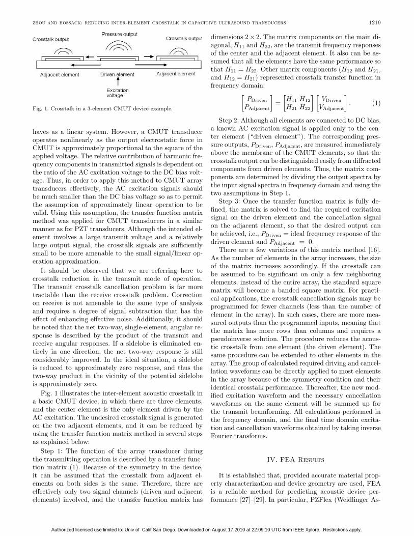
Fig. 1. Crosstalk in a 3-element CMUT device example.
haves as a linear system. However, a CMUT transduceroperates nonlinearly as the output electrostatic force inCMUT is approximately proportional to the square of theapplied voltage. The relative contribution of harmonic fre-quency components in transmitted signals is dependent onthe ratio of the AC excitation voltage to the DC bias volt-age. Thus, in order to apply this method to CMUT arraytransducers effectively, the AC excitation signals shouldbe much smaller than the DC bias voltage so as to permitthe assumption of approximately linear operation to bevalid. Using this assumption, the transfer function matrixmethod was applied for CMUT transducers in a similarmanner as for PZT transducers. Although the intended el-ement involves a large transmit voltage and a relativelylarge output signal, the crosstalk signals are sufficientlysmall to be more amenable to the small signal/linear op-eration approximation.
It should be observed that we are referring here tocrosstalk reduction in the transmit mode of operation.The transmit crosstalk cancellation problem is far moretractable than the receive crosstalk problem. Correctionon receive is not amenable to the same type of analysisand requires a degree of signal subtraction that has theeffect of enhancing effective noise. Additionally, it shouldbe noted that the net two-way, single-element, angular re-sponse is described by the product of the transmit andreceive angular responses. If a sidelobe is eliminated en-tirely in one direction, the net two-way response is stillconsiderably improved. In the ideal situation, a sidelobeis reduced to approximately zero response, and thus thetwo-way product in the vicinity of the potential sidelobeis approximately zero.
Fig. 1 illustrates the inter-element acoustic crosstalk ina basic CMUT device, in which there are three elements,and the center element is the only element driven by theAC excitation. The undesired crosstalk signal is generatedon the two adjacent elements, and it can be reduced byusing the transfer function matrix method in several stepsas explained below:
Step 1: The function of the array transducer duringthe transmitting operation is described by a transfer func-tion matrix (1). Because of the symmetry in the device,it can be assumed that the crosstalk from adjacent el-ements on both sides is the same. Therefore, there areeffectively only two signal channels (driven and adjacentelements) involved, and the transfer function matrix has
dimensions 2 × 2. The matrix components on the main di-agonal, H11 and H22, are the transmit frequency responsesof the center and the adjacent element. It also can be as-sumed that all the elements have the same performance sothat H11 = H22. Other matrix components (H12 and H21,and H12 = H21) represented crosstalk transfer function infrequency domain:[
PDrivenPAdjacent
]=
[H11 H12H21 H22
][VDriven
VAdjacent
]. (1)
Step 2: Although all elements are connected to DC bias,a known AC excitation signal is applied only to the cen-ter element (“driven element”). The corresponding pres-sure outputs, PDriven, PAdjacent, are measured immediatelyabove the membrane of the CMUT elements, so that thecrosstalk output can be distinguished easily from diffractedcomponents from driven elements. Thus, the matrix com-ponents are determined by dividing the output spectra bythe input signal spectra in frequency domain and using thetwo assumptions in Step 1.
Step 3: Once the transfer function matrix is fully de-fined, the matrix is solved to find the required excitationsignal on the driven element and the cancellation signalon the adjacent element, so that the desired output canbe achieved, i.e., PDriven = ideal frequency response of thedriven element and PAdjacent = 0.
There are a few variations of this matrix method [16].As the number of elements in the array increases, the sizeof the matrix increases accordingly. If the crosstalk canbe assumed to be significant on only a few neighboringelements, instead of the entire array, the standard squarematrix will become a banded square matrix. For practi-cal applications, the crosstalk cancellation signals may beprogrammed for fewer channels (less than the number ofelement in the array). In such cases, there are more mea-sured outputs than the programmed inputs, meaning thatthe matrix has more rows than columns and requires apseudoinverse solution. The procedure reduces the acous-tic crosstalk from one element (the driven element). Thesame procedure can be extended to other elements in thearray. The group of calculated required driving and cancel-lation waveforms can be directly applied to most elementsin the array because of the symmetry condition and theiridentical crosstalk performance. Thereafter, the new mod-ified excitation waveform and the necessary cancellationwaveforms on the same element will be summed up forthe transmit beamforming. All calculations performed inthe frequency domain, and the final time domain excita-tion and cancellation waveforms obtained by taking inverseFourier transforms.
IV. FEA Results
It is established that, provided accurate material prop-erty characterization and device geometry are used, FEAis a reliable method for predicting acoustic device per-formance [27]–[29]. In particular, PZFlex (Weidlinger As-
Authorized licensed use limited to: Univ of Calif San Diego. Downloaded on August 17,2010 at 22:09:10 UTC from IEEE Xplore. Restrictions apply.
1220 ieee transactions on ultrasonics, ferroelectrics, and frequency control, vol. 54, no. 6, june 2007
TABLE IPrincipal Dimensions and Material Properties.
Young’sDensity modulus Poisson’s Relative
Material (kg/m3) (×109 Pa) ratio permittivity
Silicon 2340 165 0.22 11.5Silicon nitride 3270 323 0.26 7.5Polyurethane 1122 0.97 0.43 4.0
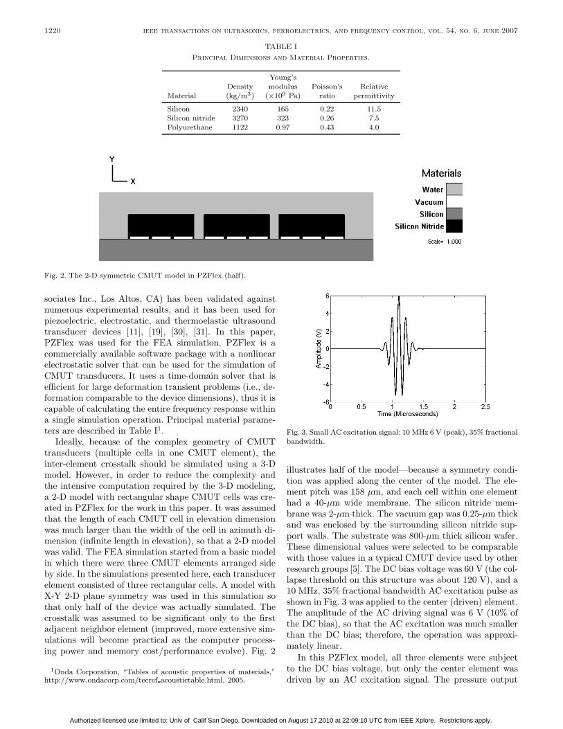
Fig. 2. The 2-D symmetric CMUT model in PZFlex (half).
sociates Inc., Los Altos, CA) has been validated againstnumerous experimental results, and it has been used forpiezoelectric, electrostatic, and thermoelastic ultrasoundtransducer devices [11], [19], [30], [31]. In this paper,PZFlex was used for the FEA simulation. PZFlex is acommercially available software package with a nonlinearelectrostatic solver that can be used for the simulation ofCMUT transducers. It uses a time-domain solver that isefficient for large deformation transient problems (i.e., de-formation comparable to the device dimensions), thus it iscapable of calculating the entire frequency response withina single simulation operation. Principal material parame-ters are described in Table I1.
Ideally, because of the complex geometry of CMUTtransducers (multiple cells in one CMUT element), theinter-element crosstalk should be simulated using a 3-Dmodel. However, in order to reduce the complexity andthe intensive computation required by the 3-D modeling,a 2-D model with rectangular shape CMUT cells was cre-ated in PZFlex for the work in this paper. It was assumedthat the length of each CMUT cell in elevation dimensionwas much larger than the width of the cell in azimuth di-mension (infinite length in elevation), so that a 2-D modelwas valid. The FEA simulation started from a basic modelin which there were three CMUT elements arranged sideby side. In the simulations presented here, each transducerelement consisted of three rectangular cells. A model withX-Y 2-D plane symmetry was used in this simulation sothat only half of the device was actually simulated. Thecrosstalk was assumed to be significant only to the firstadjacent neighbor element (improved, more extensive sim-ulations will become practical as the computer process-ing power and memory cost/performance evolve). Fig. 2
1Onda Corporation, “Tables of acoustic properties of materials,”http://www.ondacorp.com/tecref acoustictable.html, 2005.
Fig. 3. Small AC excitation signal: 10 MHz 6 V (peak), 35% fractionalbandwidth.
illustrates half of the model—because a symmetry condi-tion was applied along the center of the model. The ele-ment pitch was 158 µm, and each cell within one elementhad a 40-µm wide membrane. The silicon nitride mem-brane was 2-µm thick. The vacuum gap was 0.25-µm thickand was enclosed by the surrounding silicon nitride sup-port walls. The substrate was 800-µm thick silicon wafer.These dimensional values were selected to be comparablewith those values in a typical CMUT device used by otherresearch groups [5]. The DC bias voltage was 60 V (the col-lapse threshold on this structure was about 120 V), and a10 MHz, 35% fractional bandwidth AC excitation pulse asshown in Fig. 3 was applied to the center (driven) element.The amplitude of the AC driving signal was 6 V (10% ofthe DC bias), so that the AC excitation was much smallerthan the DC bias; therefore, the operation was approxi-mately linear.
In this PZFlex model, all three elements were subjectto the DC bias voltage, but only the center element wasdriven by an AC excitation signal. The pressure output
Authorized licensed use limited to: Univ of Calif San Diego. Downloaded on August 17,2010 at 22:09:10 UTC from IEEE Xplore. Restrictions apply.
zhou and hossack: reducing inter-element crosstalk in capacitive ultrasound transducers 1221
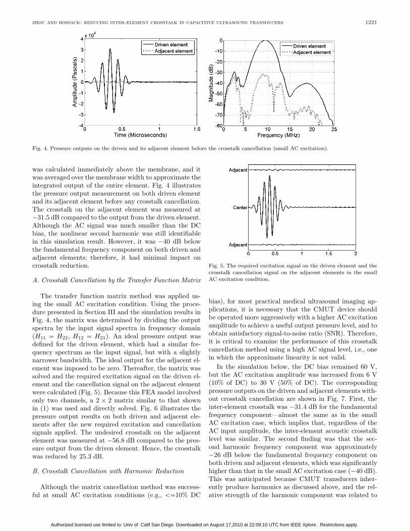
Fig. 4. Pressure outputs on the driven and its adjacent element before the crosstalk cancellation (small AC excitation).
was calculated immediately above the membrane, and itwas averaged over the membrane width to approximate theintegrated output of the entire element. Fig. 4 illustratesthe pressure output measurement on both driven elementand its adjacent element before any crosstalk cancellation.The crosstalk on the adjacent element was measured at−31.5 dB compared to the output from the driven element.Although the AC signal was much smaller than the DCbias, the nonlinear second harmonic was still identifiablein this simulation result. However, it was −40 dB belowthe fundamental frequency component on both driven andadjacent elements; therefore, it had minimal impact oncrosstalk reduction.
A. Crosstalk Cancellation by the Transfer Function Matrix
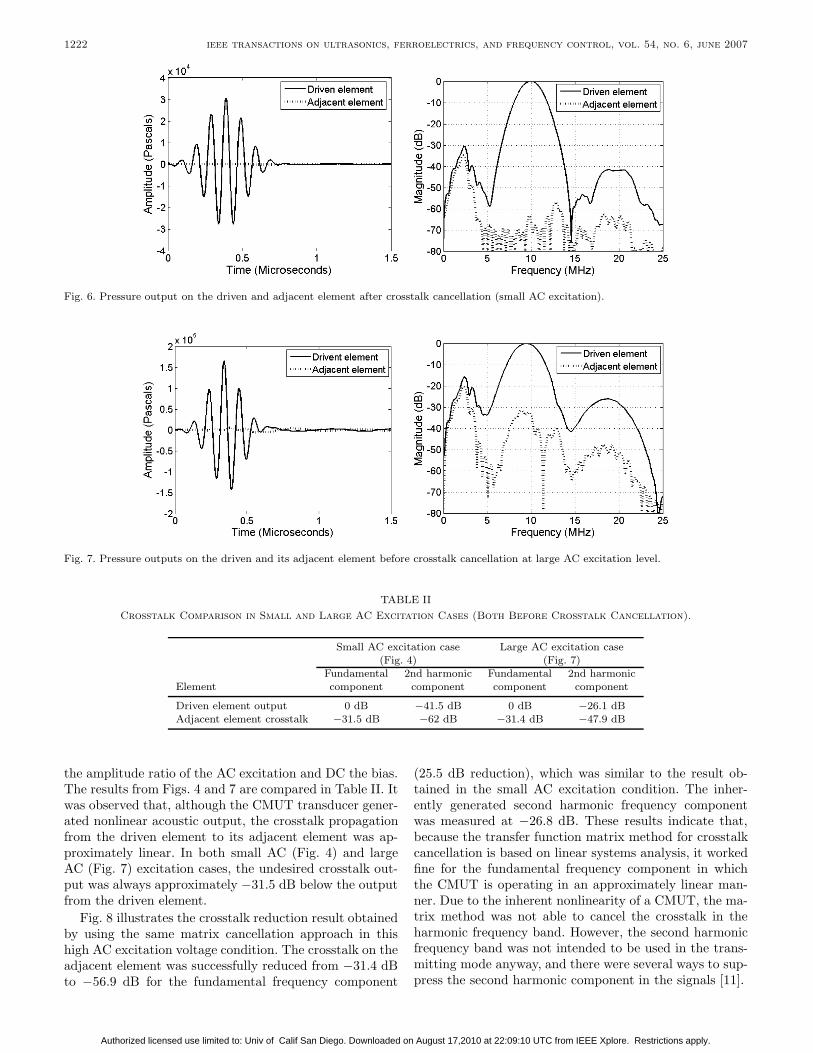
The transfer function matrix method was applied us-ing the small AC excitation condition. Using the proce-dure presented in Section III and the simulation results inFig. 4, the matrix was determined by dividing the outputspectra by the input signal spectra in frequency domain(H11 = H22, H12 = H21). An ideal pressure output wasdefined for the driven element, which had a similar fre-quency spectrum as the input signal, but with a slightlynarrower bandwidth. The ideal output for the adjacent el-ement was imposed to be zero. Thereafter, the matrix wassolved and the required excitation signal on the driven el-ement and the cancellation signal on the adjacent elementwere calculated (Fig. 5). Because this FEA model involvedonly two channels, a 2 × 2 matrix similar to that shownin (1) was used and directly solved. Fig. 6 illustrates thepressure output results on both driven and adjacent ele-ments after the new required excitation and cancellationsignals applied. The undesired crosstalk on the adjacentelement was measured at −56.8 dB compared to the pres-sure output from the driven element. Hence, the crosstalkwas reduced by 25.3 dB.
B. Crosstalk Cancellation with Harmonic Reduction
Although the matrix cancellation method was success-ful at small AC excitation conditions (e.g., <=10% DC
Fig. 5. The required excitation signal on the driven element and thecrosstalk cancellation signal on the adjacent elements in the smallAC excitation condition.
bias), for most practical medical ultrasound imaging ap-plications, it is necessary that the CMUT device shouldbe operated more aggressively with a higher AC excitationamplitude to achieve a useful output pressure level, and toobtain satisfactory signal-to-noise ratio (SNR). Therefore,it is critical to examine the performance of this crosstalkcancellation method using a high AC signal level, i.e., onein which the approximate linearity is not valid.
In the simulation below, the DC bias remained 60 V,but the AC excitation amplitude was increased from 6 V(10% of DC) to 30 V (50% of DC). The correspondingpressure outputs on the driven and adjacent elements with-out crosstalk cancellation are shown in Fig. 7. First, theinter-element crosstalk was −31.4 dB for the fundamentalfrequency component—almost the same as in the smallAC excitation case, which implies that, regardless of theAC input amplitude, the inter-element acoustic crosstalklevel was similar. The second finding was that the sec-ond harmonic frequency component was approximately−26 dB below the fundamental frequency component onboth driven and adjacent elements, which was significantlyhigher than that in the small AC excitation case (−40 dB).This was anticipated because CMUT transducers inher-ently produce harmonics as discussed above, and the rel-ative strength of the harmonic component was related to
Authorized licensed use limited to: Univ of Calif San Diego. Downloaded on August 17,2010 at 22:09:10 UTC from IEEE Xplore. Restrictions apply.
1222 ieee transactions on ultrasonics, ferroelectrics, and frequency control, vol. 54, no. 6, june 2007
Fig. 6. Pressure output on the driven and adjacent element after crosstalk cancellation (small AC excitation).
Fig. 7. Pressure outputs on the driven and its adjacent element before crosstalk cancellation at large AC excitation level.
TABLE IICrosstalk Comparison in Small and Large AC Excitation Cases (Both Before Crosstalk Cancellation).
Small AC excitation case Large AC excitation case(Fig. 4) (Fig. 7)
Fundamental 2nd harmonic Fundamental 2nd harmonicElement component component component component
Driven element output 0 dB −41.5 dB 0 dB −26.1 dBAdjacent element crosstalk −31.5 dB −62 dB −31.4 dB −47.9 dB
the amplitude ratio of the AC excitation and DC the bias.The results from Figs. 4 and 7 are compared in Table II. Itwas observed that, although the CMUT transducer gener-ated nonlinear acoustic output, the crosstalk propagationfrom the driven element to its adjacent element was ap-proximately linear. In both small AC (Fig. 4) and largeAC (Fig. 7) excitation cases, the undesired crosstalk out-put was always approximately −31.5 dB below the outputfrom the driven element.
Fig. 8 illustrates the crosstalk reduction result obtainedby using the same matrix cancellation approach in thishigh AC excitation voltage condition. The crosstalk on theadjacent element was successfully reduced from −31.4 dBto −56.9 dB for the fundamental frequency component
(25.5 dB reduction), which was similar to the result ob-tained in the small AC excitation condition. The inher-ently generated second harmonic frequency componentwas measured at −26.8 dB. These results indicate that,because the transfer function matrix method for crosstalkcancellation is based on linear systems analysis, it workedfine for the fundamental frequency component in whichthe CMUT is operating in an approximately linear man-ner. Due to the inherent nonlinearity of a CMUT, the ma-trix method was not able to cancel the crosstalk in theharmonic frequency band. However, the second harmonicfrequency band was not intended to be used in the trans-mitting mode anyway, and there were several ways to sup-press the second harmonic component in the signals [11].
Authorized licensed use limited to: Univ of Calif San Diego. Downloaded on August 17,2010 at 22:09:10 UTC from IEEE Xplore. Restrictions apply.
zhou and hossack: reducing inter-element crosstalk in capacitive ultrasound transducers 1223
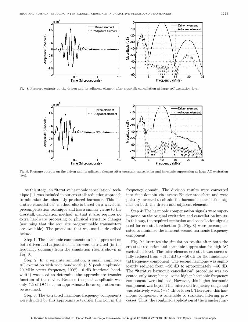
Fig. 8. Pressure outputs on the driven and its adjacent element after crosstalk cancellation at large AC excitation level.
Fig. 9. Pressure outputs on the driven and its adjacent element after crosstalk cancellation and harmonic suppression at large AC excitationlevel.
At this stage, an “iterative harmonic cancellation” tech-nique [11] was included in our crosstalk reduction approachto minimize the inherently produced harmonic. This “it-erative cancellation” method also is based on a waveformprecompensation technique and has a similar virtue to thecrosstalk cancellation method, in that it also requires noextra hardware processing or physical structure changes(assuming that the requisite programmable transmittersare available). The procedure that was used is describedbelow.
Step 1: The harmonic components to be suppressed onboth driven and adjacent elements were extracted (in thefrequency domain) from the simulation results shown inFig. 8.
Step 2: In a separate simulation, a small amplitudeAC excitation with wide bandwidth (3 V peak amplitude,20 MHz center frequency, 100% −6 dB fractional band-width) was used to determine the approximate transferfunction of the device. Because the peak amplitude wasonly 5% of DC bias, an approximate linear operation canbe assumed.
Step 3: The extracted harmonic frequency componentswere divided by this approximate transfer function in the
frequency domain. The division results were convertedinto time domain via inverse Fourier transform and werepolarity-inverted to obtain the harmonic cancellation sig-nals on both the driven and adjacent elements.
Step 4: The harmonic compensation signals were super-imposed on the original excitation and cancellation inputs.In this way, the required excitation and cancellation signalsused for crosstalk reduction (in Fig. 8) were precompen-sated to minimize the inherent second harmonic frequencycomponent.
Fig. 9 illustrates the simulation results after both thecrosstalk reduction and harmonic suppression for high ACexcitation level. The inter-element crosstalk was success-fully reduced from −31.4 dB to −50 dB for the fundamen-tal frequency component. The second harmonic was signif-icantly reduced from −26 dB to approximately −50 dB.The “iterative harmonic cancellation” procedure was ex-ecuted only once; hence, some higher harmonic frequencycomponents were induced. However, this higher harmoniccomponent was beyond the interested frequency range andwas relatively weak (−35 dB or lower). Therefore, this har-monic component is amenable to standard filtering pro-cesses. Thus, the combined application of the transfer func-
Authorized licensed use limited to: Univ of Calif San Diego. Downloaded on August 17,2010 at 22:09:10 UTC from IEEE Xplore. Restrictions apply.
1224 ieee transactions on ultrasonics, ferroelectrics, and frequency control, vol. 54, no. 6, june 2007
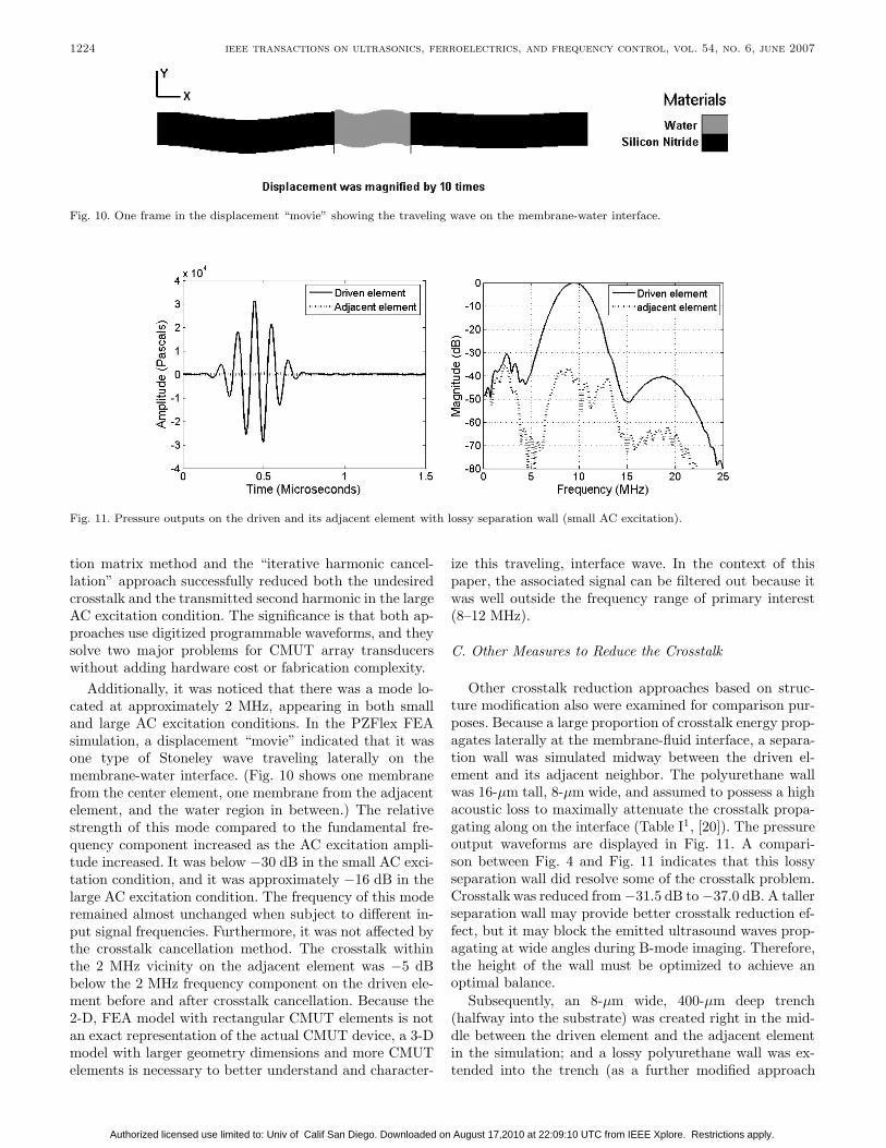
Fig. 10. One frame in the displacement “movie” showing the traveling wave on the membrane-water interface.
Fig. 11. Pressure outputs on the driven and its adjacent element with lossy separation wall (small AC excitation).
tion matrix method and the “iterative harmonic cancel-lation” approach successfully reduced both the undesiredcrosstalk and the transmitted second harmonic in the largeAC excitation condition. The significance is that both ap-proaches use digitized programmable waveforms, and theysolve two major problems for CMUT array transducerswithout adding hardware cost or fabrication complexity.
Additionally, it was noticed that there was a mode lo-cated at approximately 2 MHz, appearing in both smalland large AC excitation conditions. In the PZFlex FEAsimulation, a displacement “movie” indicated that it wasone type of Stoneley wave traveling laterally on themembrane-water interface. (Fig. 10 shows one membranefrom the center element, one membrane from the adjacentelement, and the water region in between.) The relativestrength of this mode compared to the fundamental fre-quency component increased as the AC excitation ampli-tude increased. It was below −30 dB in the small AC exci-tation condition, and it was approximately −16 dB in thelarge AC excitation condition. The frequency of this moderemained almost unchanged when subject to different in-put signal frequencies. Furthermore, it was not affected bythe crosstalk cancellation method. The crosstalk withinthe 2 MHz vicinity on the adjacent element was −5 dBbelow the 2 MHz frequency component on the driven ele-ment before and after crosstalk cancellation. Because the2-D, FEA model with rectangular CMUT elements is notan exact representation of the actual CMUT device, a 3-Dmodel with larger geometry dimensions and more CMUTelements is necessary to better understand and character-
ize this traveling, interface wave. In the context of thispaper, the associated signal can be filtered out because itwas well outside the frequency range of primary interest(8–12 MHz).
C. Other Measures to Reduce the Crosstalk
Other crosstalk reduction approaches based on struc-ture modification also were examined for comparison pur-poses. Because a large proportion of crosstalk energy prop-agates laterally at the membrane-fluid interface, a separa-tion wall was simulated midway between the driven el-ement and its adjacent neighbor. The polyurethane wallwas 16-µm tall, 8-µm wide, and assumed to possess a highacoustic loss to maximally attenuate the crosstalk propa-gating along on the interface (Table I1, [20]). The pressureoutput waveforms are displayed in Fig. 11. A compari-son between Fig. 4 and Fig. 11 indicates that this lossyseparation wall did resolve some of the crosstalk problem.Crosstalk was reduced from −31.5 dB to −37.0 dB. A tallerseparation wall may provide better crosstalk reduction ef-fect, but it may block the emitted ultrasound waves prop-agating at wide angles during B-mode imaging. Therefore,the height of the wall must be optimized to achieve anoptimal balance.
Subsequently, an 8-µm wide, 400-µm deep trench(halfway into the substrate) was created right in the mid-dle between the driven element and the adjacent elementin the simulation; and a lossy polyurethane wall was ex-tended into the trench (as a further modified approach
Authorized licensed use limited to: Univ of Calif San Diego. Downloaded on August 17,2010 at 22:09:10 UTC from IEEE Xplore. Restrictions apply.
zhou and hossack: reducing inter-element crosstalk in capacitive ultrasound transducers 1225
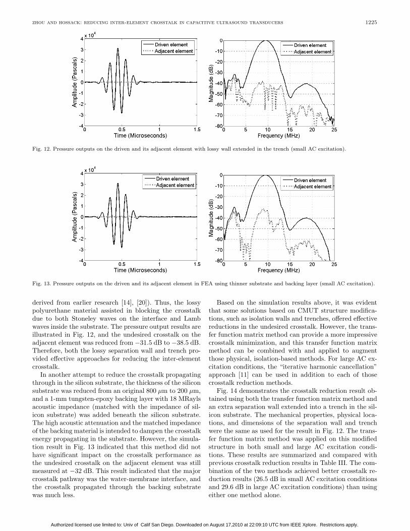
Fig. 12. Pressure outputs on the driven and its adjacent element with lossy wall extended in the trench (small AC excitation).
Fig. 13. Pressure outputs on the driven and its adjacent element in FEA using thinner substrate and backing layer (small AC excitation).
derived from earlier research [14], [20]). Thus, the lossypolyurethane material assisted in blocking the crosstalkdue to both Stoneley waves on the interface and Lambwaves inside the substrate. The pressure output results areillustrated in Fig. 12, and the undesired crosstalk on theadjacent element was reduced from −31.5 dB to −38.5 dB.Therefore, both the lossy separation wall and trench pro-vided effective approaches for reducing the inter-elementcrosstalk.
In another attempt to reduce the crosstalk propagatingthrough in the silicon substrate, the thickness of the siliconsubstrate was reduced from an original 800 µm to 200 µm,and a 1-mm tungsten-epoxy backing layer with 18 MRaylsacoustic impedance (matched with the impedance of sil-icon substrate) was added beneath the silicon substrate.The high acoustic attenuation and the matched impedanceof the backing material is intended to dampen the crosstalkenergy propagating in the substrate. However, the simula-tion result in Fig. 13 indicated that this method did nothave significant impact on the crosstalk performance asthe undesired crosstalk on the adjacent element was stillmeasured at −32 dB. This result indicated that the majorcrosstalk pathway was the water-membrane interface, andthe crosstalk propagated through the backing substratewas much less.
Based on the simulation results above, it was evidentthat some solutions based on CMUT structure modifica-tions, such as isolation walls and trenches, offered effectivereductions in the undesired crosstalk. However, the trans-fer function matrix method can provide a more impressivecrosstalk minimization, and this transfer function matrixmethod can be combined with and applied to augmentthose physical, isolation-based methods. For large AC ex-citation conditions, the “iterative harmonic cancellation”approach [11] can be used in addition to each of thosecrosstalk reduction methods.
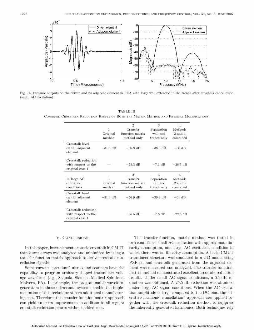
Fig. 14 demonstrates the crosstalk reduction result ob-tained using both the transfer function matrix method andan extra separation wall extended into a trench in the sil-icon substrate. The mechanical properties, physical loca-tions, and dimensions of the separation wall and trenchwere the same as used for the result in Fig. 12. The trans-fer function matrix method was applied on this modifiedstructure in both small and large AC excitation condi-tions. These results are summarized and compared withprevious crosstalk reduction results in Table III. The com-bination of the two methods achieved better crosstalk re-duction results (26.5 dB in small AC excitation conditionsand 29.6 dB in large AC excitation conditions) than usingeither one method alone.
Authorized licensed use limited to: Univ of Calif San Diego. Downloaded on August 17,2010 at 22:09:10 UTC from IEEE Xplore. Restrictions apply.
1226 ieee transactions on ultrasonics, ferroelectrics, and frequency control, vol. 54, no. 6, june 2007
Fig. 14. Pressure outputs on the driven and its adjacent element in FEA with lossy wall extended in the trench after crosstalk cancellation(small AC excitation).
TABLE IIICombined Crosstalk Reduction Result of Both the Matrix Method and Physical Modifications.
2 3 41 Transfer Separation Methods
Original function matrix wall and 2 and 3method method only trench only combined
Crosstalk levelon the adjacent −31.5 dB −56.8 dB −38.6 dB −58 dBelement
Crosstalk reductionwith respect to the — −25.3 dB −7.1 dB −26.5 dBoriginal case 1
2 3 4In large AC 1 Transfer Separation Methodsexcitation Original function matrix wall and 2 and 3conditions method method only trench only combined
Crosstalk levelon the adjacent −31.4 dB −56.9 dB −39.2 dB −61 dBelement
Crosstalk reductionwith respect to the −25.5 dB −7.8 dB −29.6 dBoriginal case 1
V. Conclusions
In this paper, inter-element acoustic crosstalk in CMUTtransducer arrays was analyzed and minimized by using atransfer function matrix approach to derive crosstalk can-cellation signals.
Some current “premium” ultrasound scanners have thecapability to program arbitrary-shaped transmitter volt-age waveforms (e.g., Sequoia, Siemens Medical Solutions,Malvern, PA). In principle, the programmable waveformgenerators in those ultrasound systems enable the imple-mentation of this technique at zero additional manufactur-ing cost. Therefore, this transfer function matrix approachcan yield an extra improvement in addition to all regularcrosstalk reduction efforts without added cost.
The transfer-function, matrix method was tested intwo conditions: small AC excitation with approximate lin-earity assumption, and large AC excitation condition inwhich there was no linearity assumption. A basic CMUTtransducer structure was simulated in a 2-D model usingPZFlex, and crosstalk generated from the adjacent ele-ment was measured and analyzed. The transfer-function,matrix method demonstrated excellent crosstalk reductionresults. Under small AC signal conditions, a 25 dB re-duction was obtained. A 25.5 dB reduction was obtainedunder large AC signal conditions. When the AC excita-tion amplitude is large compared to the DC bias, the “it-erative harmonic cancellation” approach was applied to-gether with the crosstalk reduction method to suppressthe inherently generated harmonics. Both techniques rely
Authorized licensed use limited to: Univ of Calif San Diego. Downloaded on August 17,2010 at 22:09:10 UTC from IEEE Xplore. Restrictions apply.
zhou and hossack: reducing inter-element crosstalk in capacitive ultrasound transducers 1227
on programmable waveforms, and applying both of themtogether reduces the undesired, inter-element crosstalk andthe transmitted harmonics without adding hardware costor CMUT fabrication complexity. Several other crosstalkreduction approaches also were demonstrated to be ef-fective ways to reduce the inter-element crosstalk, suchas lossy separation walls and trenches. Moreover, thetransfer-function, matrix method was applied on a physi-cally modified CMUT structure (with an extra separationwall extended in a trench). The combined result produceda 26.5 dB crosstalk reduction in small AC excitation con-ditions and 29.6 dB in large AC excitation conditions.
This matrix approach may be applied for array trans-ducers in a relatively straightforward manner in the trans-mit mode. One limitation of this method is that, for highamplitude, wide-band input signal, the inherent nonlin-earity cannot be ignored, and the second harmonics ofsome low-frequency components still are located in thefundamental frequency band of the entire signal. This willsomewhat affect the effectiveness of this linear crosstalkreduction method. In the receive mode, it is more prob-lematic to attempt to remove the effects of crosstalk dueto the compounded nature of the received data resultingfrom the desired element response and the crosstalk com-ponent added from adjacent elements. A signal subtrac-tion approach could be used, but this inevitably wouldreduce SNR. The crosstalk investigation in this paper wasfocused on crosstalk in 1-D CMUT arrays using two dimen-sional FEA modeling. Further study and 3-D simulationof CMUT transducers (including multiple cell examples)will improve the understanding of the crosstalk in CMUTsand assist in making further contributions in crosstalk re-duction.
Acknowledgment
Paul Reynolds, Ph.D. (Weidlinger Associates Inc., LosAltos, CA) provided guidance on PZFlex finite elementmodeling.
References
[1] O. Oralkan, A. Ergun, J. Johnson, M. Karaman, U. Demirci,K. Kaviani, T. Lee, and B. Khuri-Yakub, “Capacitive microma-chined ultrasonic transducers: Next-generation arrays for acous-tic imaging?,,” IEEE Trans. Ultrason., Ferroelect., Freq. Contr.,vol. 49, pp. 1596–1610, 2002.
[2] O. Oralkan, X. Zhuang, I. Wygant, D. Yeh, A. Nikoozadeh,A. Ergun, M. Karaman, and B. Khuri-Yakub, “Integratedultrasonic imaging systems based on CMUT arrays: Recentprogress,” in Proc. IEEE Ultrason. Symp., 2004, pp. 391–394.
[3] J. Gelly and F. Lanteri, “Comparison of piezoelectric (thicknessmode) and MEMS transducers,” in Proc. IEEE Ultrason. Symp.,2003, pp. 1965–1974.
[4] D. M. Mills, “Medical imaging with capacitive micromachinedultrasound transducer (cMUT) arrays,” in Proc. IEEE Ultrason.Symp., 2004, pp. 384–390.
[5] J. Knight, J. McLean, and F. Degertekin, “Low temperaturefabrication of immersion capacitive micromachined ultrasonictransducers on silicon and dielectric substrate,” IEEE Trans.Ultrason., Ferroelect., Freq. Contr., vol. 51, pp. 1324–1333, 2004.
[6] C. Daft, P. Wagner, B. Bymaster, S. Panda, K. Patel, and I.Ladabaum, “CMUTs and electronics for 2-D and 3-D imaging:Monolithic integration, in-handle chip sets and system implica-tions,” in Proc. IEEE Ultrason. Symp., 2005, pp. 463–474.
[7] O. Oralkan, A. Ergun, C.-H. Cheng, J. Johnson, M. Kara-man, T. H. Lee, and B. Khuri-Yakub, “Volumetric imaging us-ing 2-D capacitive micromachined ultrasonic transducer arrays(cMUTs): Initial results,” in Proc. IEEE Ultrason. Symp., 2002,pp. 1083–1086.
[8] J. Knight and L. Degertekin, “Capacitive ultrasonic transducersfor forward looking intravascular imaging arrays,” in Proc. IEEEUltrason. Symp., 2002, pp. 1052–1055.
[9] D. Mills and L. Scott, “Real-time in-vivo imaging with capacitivemicromachined ultrasound transducer (cMUT) linear arrays,” inProc. IEEE Ultrason. Symp., 2003, pp. 568–571.
[10] G. Yaralioglu, A. Ergun, B. Bayram, E. Haeggstrom, and B.Khuri-Yakub, “Calculation and measurement of electromechan-ical coupling coefficient of capacitive micromachined ultrasonictransducers,” IEEE Trans. Ultrason., Ferroelect., Freq. Contr.,vol. 50, pp. 449–456, 2003.
[11] S. Zhou, P. Reynolds, and J. Hossack, “Pre-compensated ex-citation waveforms to suppress harmonic generation in MEMSelectrostatic transducers,” IEEE Trans. Ultrason., Ferroelect.,Freq. Contr., vol. 51, pp. 1564–1574, 2004.
[12] B. Savord and W. Ossman, “Circuit and method for exciting amicro-machined transducer to have low second order harmonictransmit energy,” U.S. Patent 6,292,435, (provisionally filed inMay 1999) 2001.
[13] J. Fraser, “Capacitive micromachined ultrasonic transduc-ers,” U.S. Patent 6,443,901.
[14] X. Jin, O. Oralkan, F. Degertekin, and B. Khuri-Yakub, “Char-acterization of one-dimensional capacitive micromachined ul-trasonic immersion transducer arrays,” IEEE Trans. Ultrason.,Ferroelect., Freq. Contr., vol. 48, pp. 750–760, 2001.
[15] A. Caronti, R. Carotenuto, G. Caliano, M. Pappalardo, and E.Cianci, “A finite element study of cross coupling in 1-D capaci-tive micromachined ultrasonic transducer arrays,” in Proc. IEEEUltrason. Symp., 2002, pp. 1059–1062.
[16] S. Zhou, G. Wojcik, and J. Hossack, “An approach for reducingadjacent element crosstalk in ultrasound arrays,” IEEE Trans.Ultrason., Ferroelect., Freq. Contr., vol. 50, pp. 1752–1761, 2003.
[17] C. Desilets, “Medical ultrasonic transducer array design and ap-plications,” presented at Short course given at IEEE UltrasonicsSymposium, 1997, Toronto, Ontario, Canada.
[18] G. S. Kino and R. Baer, “Theory for cross-coupling,” in Proc.IEEE Ultrason. Symp., 1983, pp. 1013–1019.
[19] G. Wojcik, J. Mould, P. Reynolds, A. Fitzgerald, P. Wagner, andI. Ladabaum, “Time-domain models of MUT array cross-talk insilicon substrates,” in Proc. IEEE Ultrason. Symp., 2000, pp.909–914.
[20] Y. Roh and B. Khuri-Yakub, “Finite element analysis of under-water capacitor micromachined ultrasonic transducers,” IEEETrans. Ultrason., Ferroelect., Freq. Contr., vol. 49, pp. 293–298,2002.
[21] P.-C. Eccardt, A. Lohfink, and H.-G. Garssen, “Analysis ofcrosstalk between fluid coupled cmut membranes,” in Proc.IEEE Ultrason. Symp., 2005, pp. 593–596.
[22] N. Felix, E. Lacaze, M. Lethiecq, and F. Patat, “Experimentalinvestigation of cross-coupling and its Influence on the elemen-tary radiation pattern in 1-D ultrasound arrays,” in Proc. IEEEUltrason. Symp., 1999, pp. 1053–1056.
[23] N. Lamberti, “Radiation pattern distortion caused by the in-terelement coupling in linear array transducers,” in Proc. IEEEUltrason. Symp., 1999, pp. 1071–1075.
[24] J. Assaad and C. Bruneel, “Radiation from finite phased and fo-cused linear array including interaction,” J. Acoust. Soc. Amer.,vol. 101, pp. 1859–1867, 1997.
[25] J.-H. Mo, J. Fowlkes, A. L. Robinson, and P. Carson, “Crosstalkreduction with a micromachined diaphragm structure for inte-grated ultrasound transducer arrays,” IEEE Trans. Ultrason.,Ferroelect., Freq. Contr., vol. 39, pp. 48–53, 1992.
[26] C. Cole, A. Gee, and T. Lui, “Method and apparatus for trans-mit beamformer,” U.S. patent No. 5,675,554, 1996.
[27] N. N. Abboud, G. Wojcik, D. Vaughan, J. Mould, D. Powell,and L. Nikodym, “Finite element modeling for ultrasonic trans-ducers,” in Proc. SPIE Int. Symp. Medical Imaging, 1998, pp.19–24.
Authorized licensed use limited to: Univ of Calif San Diego. Downloaded on August 17,2010 at 22:09:10 UTC from IEEE Xplore. Restrictions apply.
1228 ieee transactions on ultrasonics, ferroelectrics, and frequency control, vol. 54, no. 6, june 2007
[28] G. L. Wojcik, D. K. Vaughan, N. Abboud, and J. Mould, “Elec-tromechanical modeling using explicit time domain finite ele-ments,” in Proc. IEEE Ultrason. Symp., 1993, pp. 1107–1112.
[29] D. Powell, G. Wojcik, C. S. DeSilets, T. R. Gururaja, K.Guggenberger, S. Sherrit, and B. K. Mukerjee, “Incremental‘Model-build-test’ validation exercise for 1-D biomedical ultra-sonic imaging array,” in Proc. IEEE Ultrason. Symp., 1997, pp.1669–1674.
[30] G. Wojcik, D. K. Vaughn, V. Murray, and J. Mould, “Time do-main modeling of composite arrays for underwater imaging,” inProc. IEEE Ultrason. Symp., 1994, pp. 1027–1032.
[31] S. Zhou, P. Reynolds, R. Krause, T. Buma, M. O’Donnell, and J.Hossack, “Finite-element analysis of material and parameter ef-fects in laser-based thermoelastic ultrasound generation,” IEEETrans. Ultrason., Ferroelect., Freq. Contr., vol. 51, pp. 1178–1186, 2004.
Shiwei Zhou was born in Beijing, China in1974. He received the B.S. and M.S. degreesin optical-electrical engineering from the Bei-jing Institute of Technology, Beijing, China, in1996 and 1999, respectively. He is currentlyworking towards the Ph.D. degree in medi-cal ultrasound imaging at the Department ofBiomedical Engineering of the University ofVirginia, Charlottesville, VA. His research in-terests are finite element analysis (FEA) mod-eling for various ultrasound transducers in-
cluding CMUTs, multi-layer transducers, and 2-D array transducers;applications of digital signal processing techniques in ultrasound; newtransducer techniques and optimization.
John A. Hossack (S’90–M’92–SM’02) wasborn in Glasgow, Scotland, in 1964. He earnedhis B.Eng. Hons(I) degree in electrical elec-tronic engineering from Strathclyde Univer-sity, Glasgow, in 1986 and his Ph.D. de-gree in the same department in 1990. From1990 to 1992, Dr. Hossack was a post doc-toral researcher in the E. L. Ginzton Labo-ratory of Stanford University working underB. A. Auld’s guidance. His research was onmodeling of 0:3 and 1:3 piezoelectric compos-ite transducers. In 1992, he joined Acuson,
Mountain View, CA, initially working on transducer design. Duringhis time at Acuson his interests diversified into beamforming and 3-Dimaging. Dr. Hossack was made a Fellow of Acuson for ‘excellence intechnical contribution’ in 1999. In 2000 he joined the Biomedical En-gineering Department at the University of Virginia, Charlottesville,VA.
His current interests are in improved 3-D ultrasound imaging andhigh bandwidth transducers/signal processing. Dr. Hossack is a mem-ber of the IEEE and serves on both the Administrative Committeeand the Technical Program Committee of the Ultrasonics Section. Healso is an Associate Editor of the IEEE Transactions on Ultrasonics,Ferroelectrics, and Frequency Control.
Authorized licensed use limited to: Univ of Calif San Diego. Downloaded on August 17,2010 at 22:09:10 UTC from IEEE Xplore. Restrictions apply.