Embed Size (px)
Citation preview
1
Crosstalk Cancellation in xDSL Systems
Chaohuang Zeng and John M. Cioffi
The authors are with the Electrical Engineering Department, Stanford University, Stanford, CA 94305, USA.
Email: [email protected].
March 30, 2001 DRAFT
2 SUBMITTED TO IEEE JOURNAL ON SELECTED AREAS IN COMMUNICATIONS: DSL
Abstract
Near-end crosstalk (NEXT) is one of the major impairments to the current ADSL downstream trans-
mission. This paper presents two methods for an ADSL receiver to cancel one (dominant) NEXT signal
from other types of services (such as HDSL, SDSL, T1, etc). The methods exploit the fact that the
crosstalk signal has a large excess bandwidth and its spectra in the main lobe and in the excess band are
strongly correlated. The principal idea is then to estimate the crosstalk in some frequency bands (e.g.,
excess band) and cancel it in other frequency bands (e.g., main lobe). The frequency-domain analysis
in this paper provides an intuitive explanation of the crosstalk estimation and cancellation, as well as a
guidance to select the right frequency bands to observe the crosstalk signal. Moreover, a fast algorithm
is proposed for practical implementation. This algorithm avoids matrix inversion and large matrix multi-
plication in every transmission block. Simulation results show that one of the proposed methods, MMSE
estimation and cancellation, is very effective to cancel one (dominant) NEXT and the improvement is
signiÞcant in terms of the data rate and the line reach for the ADSL service. For example, using a real
measured NEXT transfer function, the proposed method can increase the ADSL downstream data rate
by 200% for some loops. The methods are extended to estimate and cancel two or more crosstalkers. The
amount of improvement depends on the crosstalkers� characteristics and it is generally less than that of a
single crosstalker case.
Keywords
DSL, crosstalk, excess bandwidth, decision-aided cancellation, MMSE estimation and cancellation.
I. Introduction
Digital subscriber line (DSL) technology uses the existing phone lines to offer high speed
data transmission services to both residential and business customers. There are many
types of DSLs [1], generically referred to as xDSL, including basic rate DSL (ISDN), HDSL
(high-bit-rate DSL), ADSL (asymmetric DSL), HDSL2 (second generation HDSL), SDSL
(single-pair, symmetric DSL), and VDSL (very-high-bit-rate DSL). Of these DSLs, ISDN,
ADSL, and HDSL have been standardized by International Telecommunication Union
(ITU). ITU-T Recommendation G.995.1 [3] provides a comprehensive overview of these
standardized recommendations. HDSL2 and VDSL are currently in the process of being
standardized. SDSL is not standardized but has been deployed to offer various data rate
less than 1.536Mbps.
One of the major impairments of the xDSL systems is the severe crosstalk [2] among
the telephone lines in the same or neighboring bundles. The crosstalk is classiÞed into
DRAFT March 30, 2001
ZENG AND CIOFFI: CROSSTALK CANCELLATION IN XDSL SYSTEMS 3
near-end crosstalk (NEXT) and far-end crosstalk (FEXT). In general, NEXT is much
larger than FEXT because the interference source is closer to the receiver. Therefore,
ADSL and VDSL use frequency division duplexing (FDD) to avoid NEXTs from the same
services. However, other types of services (such as HDSL, SDSL, T1, etc.), which use
different duplexing schemes and overlap in frequency with ADSL and VDSL, may produce
detrimental NEXT. Mitigating the effect of NEXT in an ADSL receiver can dramatically
increase the data rate, the line reach, or the system operational margin.
The optimum detector for the interference cancellation can be theoretically achieved
by maximizing the a posteriori probability of the primary signal (MAP rule), which is
unfortunately too complex in practice. Some suboptimal multiuser detectors [4][5][6][7]
are proposed to mitigate or cancel the interference signal in the non-spreading system.
These detectors decode each user�s data using �soft� symbols and iterate the detection
process until a certain criterion is reached (e.g., the maximum number of iterations). The
convergence of this type of algorithms is an open problem. The algorithms are still very
complex when the signals have large constellation sizes [7].
This paper presents new practical methods to cancel or mitigate one (dominant) NEXT
for an ADSL receiver. The principal idea is to estimate the crosstalk signal in certain
frequency bands and subtract it in other frequency bands. A similar idea [8][9] has been
previously used to suppress very narrow band radio frequency interference (RFI) in VDSL
systems. The crosstalk signal to an ADSL receiver has large excess bandwidth and its
spectra in the main lobe and the excess band are strongly correlated, which gives the
opportunity to cancel the crosstalk signal in some dependent frequency bands. For ex-
ample, the crosstalk can be estimated in the excess band and cancelled in the main lobe;
vice versa. This paper provides a guidance on how to select the best frequency bands to
observe the crosstalk signal and an intuitive interpretation of the crosstalk cancellation
process. Another important aspect of the proposed techniques is that they can be im-
plemented with low computational complexity, without matrix inversion or large matrix
multiplication in each transmission block.
Previously, the fractionally-spaced equalizer (FSE) was used to suppress cyclostationary
NEXTs [10][11] if both the crosstalk signals and the primary signal are synchronized and
March 30, 2001 DRAFT
4 SUBMITTED TO IEEE JOURNAL ON SELECTED AREAS IN COMMUNICATIONS: DSL
have excess bandwidth. The FSE processes the signals� spectrum in both the main band
and the excess band. The folded spectrum after resampling to the symbol rate then
provides the ßexibility to suppress NEXTs in the main band. The problem addressed
in this paper is different mainly in the following two aspects. First, the primary signal
(ADSL) and the crosstalk signal (such as NEXT from HDSL, SDSL, T1) have completely
different modulation schemes and sampling rates. Second, the primary received signal is
decoded in the frequency domain, thus the crosstalk signal suppression is also processed
in the frequency domain. In fact, the frequency domain explanation in this paper gives an
insight on how much NEXT can be suppressed.
This paper proceeds as follows. Section II describes the system model of the primary
and crosstalk channels. Section III presents the methods to cancel the crosstalk signal and
a fast computation scheme for practical implementation. The methods are then extended
to estimate and cancel two or more crosstalkers. Simulation results are shown in Section
IV to verify the proposed methods. Section V concludes the paper.
In this paper, the notations are arranged in the following convention. A small letter, a
bold small letter, and a capital letter represent a scalar, a vector, and a matrix, respectively.
The superscript symbols T and ∗ represent �transpose� and �conjugate and transpose�
operations, respectively.
II. System Model
ADSL [12] uses the discrete multiple tone (DMT) modulation scheme [13][14] for data
transmission. DMT is an effective realization of multicarrier transmission [15][16][17],
which partitions the intersymbol interference (ISI) channel into a large number of nar-
rowband subchannels. There is no or little ISI in each subchannel if the bandwidth of
the subchannel is sufficiently narrow. The data is then transmitted in each subchannel
almost free of ISI. A subchannel is more often called a �tone� in DMT systems and this
terminology will be used in the rest of this paper.
The crosstalk signal from HDSL, SDSL, T1, or ISDN has different modulation schemes.
HDSL, SDSL, and ISDN use 2B1Q baseband transmission and T1 uses alternative mark
inversion (AMI) baseband transmission.
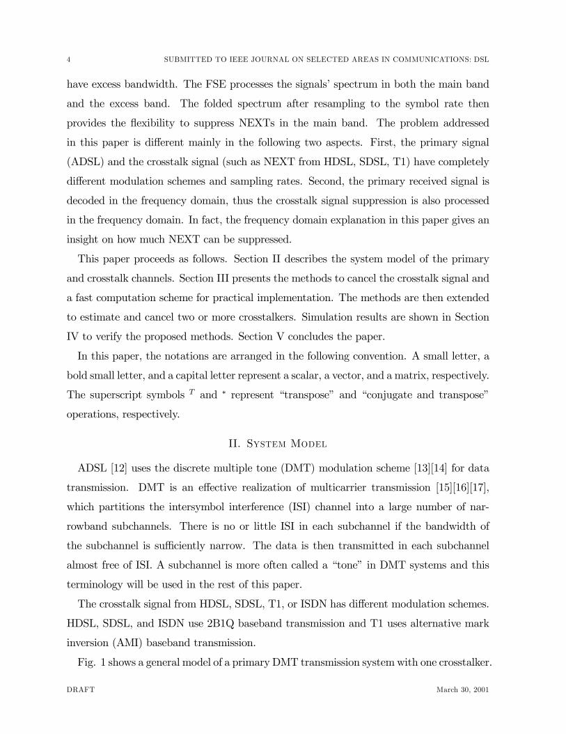
Fig. 1 shows a general model of a primary DMT transmission systemwith one crosstalker.
DRAFT March 30, 2001
ZENG AND CIOFFI: CROSSTALK CANCELLATION IN XDSL SYSTEMS 5
+
n
1/T
ai Tx Filterg(t)
Channelh(t)
Rcvr Filterhlp(t)
IFFTQ*
αααα
FFT --- Q
1/Tyi
z1/Tc
bk Tx Filtergc(t)
xTalkhc(t)
Fig. 1. The primary and crosstalk channel model.
The cyclic preÞx is not shown in the Þgure. The primary channel has a sampling rate of
1/T , but the interference signal has a sampling rate of 1/Tc at the transmitter. As a re-
sult, the received crosstalk signal is not stationary. With this general model, the received
time-domain output is
y(t) =Pi
aip(t− iT ) +Pk
bkc(t− kTc + τ) + n(t) ∗ hlp(t)| {z }�n(t)
(1)
where ai and bk are the primary transmitted signal and the crosstalk transmitted signal,
respectively. τ (0 < τ < Tc) is a fractional timing difference between the transmitted
primary signal and the crosstalk signal. p(t) and c(t) are the aggregated channel and
crosstalk responses, respectively. Mathematically (refer to Fig. 1),
p(t) = g(t) ∗ h(t) ∗ hlp(t) (2)
c(t) = gc(t) ∗ hc(t) ∗ hlp(t). (3)
Both are causal and have Þnite impulse responses. After sampling, the discrete output is
ym =Pi
aip ((m− i)T ) +Pk
bkc(mT − kTc + τ) + �nm. (4)
In DMT systems, the data is transmitted in a packet fashion. Suppose the packet
size (FFT size) is M , the above equation in one block can be represented compactly in a
matrix form:
y = Pa+ Cb+ �n, (5)
where y = [yM−1, yM−2, · · · , y0]T , a = [aM−1, aM−2, · · · , a0]T , b = [bL−1, · · · , b0, · · · , b−µ]T ,�n = [�nM−1, �nM−2, · · · , �n0]T , P and C are the channel and crosstalk responses matrices,
March 30, 2001 DRAFT
6 SUBMITTED TO IEEE JOURNAL ON SELECTED AREAS IN COMMUNICATIONS: DSL
respectively. The DMT signal has a cyclic preÞx (aM−i = a−i, i = 1, · · · , ν), therefore thechannel response matrix P is circulant and has the following form,
P =
p0 · · · pν−1 pν 0 · · · 0
0 p0 · · · pν−1 pν. . . 0
.... . .
. . .. . .
. . .. . .
. . .
0 · · · 0 p0 · · · pν−1 pν
pν 0 · · · 0 p0 · · · pν−1...
. . .. . .
. . .. . .
. . .. . .
p1 · · · pν 0 · · · 0 p0
where ν + 1 is the number of taps of the channel response p(t). The crosstalk matrix
CM×(L+µ) is
C =
c(τ − (L− 1)T c+(M − 1)T ) · · · c(τ + (M − 1)T ) · · · c(µT c+τ + (M − 1)T )c(τ − (L− 1)T c+(M − 2)T ) · · · c(τ + (M − 2)T ) · · · c(µT c+τ + (M − 2)T )
......
......
...
c(τ − (L− 1)T c+T ) · · · c(τ + T ) · · · c(µT c+τ + T )
c(τ − (L− 1)T c) · · · c(τ) · · · c(µT c+τ)
where µ+ 1 is the number of taps of the crosstalk response, L is the number of crosstalk
symbols in one DMT block (L = dMT/Tce). Note that there are many zero entries inthe above matrix C. Since the delay τ changes block over block, the matrix C varies over
different blocks.
With a cyclic preÞx, the circulant matrix P can always be decomposed [18, p. 201-2] as
P = Q∗ΛQ (6)
where Q is a fast Fourier transform (FFT) matrix, Λ is a diagonal matrix whose diagonal
elements correspond to the frequency response of the channel. More speciÞcally, the FFT
DRAFT March 30, 2001
ZENG AND CIOFFI: CROSSTALK CANCELLATION IN XDSL SYSTEMS 7
matrix is
Q =1√M
e−j2πM(M−1)(M−1) · · · e−j 2πM (M−1) 1
e−j2πM(M−2)(M−1) · · · e−j 2πM (M−2) 1...
......
...
e−j2πM(M−1) · · · e−j
2πM 1
1 · · · 1 1
and the diagonal elements of Λ from the top left to the right bottom are
diag(Λ) = Q ·
0...
pν...
p0
.
At the transmitter, the signal α is modulated in the frequency domain and transformed
into the time domain by an inverse FFT for transmission, i.e., a = Q∗α. At the receiver,
the received signal is transformed back to the frequency domain. Therefore, the whole
system model in the frequency domain is
z = Qy = Λα+QCb+ n. (7)
where z = [zM−1, zM−2, · · · , z0]T , and the white Gaussian noise n = Q�n has the same
variance as �n. The traditional system treats the crosstalk signal as Gaussian interference,
which signiÞcantly limits the overall system performance. This paper presents new meth-
ods to cancel or suppress the crosstalk component QCb in the received signal. The channel
and crosstalk responses p(t) and c(t) are assumed to be known in the ADSL receiver. The
channel response is obtained through training sequences and the crosstalk response can
be acquired by the method in [20].
III. Crosstalk Cancellation
The principal idea of crosstalk cancellation in this section is to Þrst estimate the
crosstalk signal by observing the output of certain frequency bands and then reconstruct
the crosstalk signal in other bands to cancel out the interference. If the crosstalk signal
March 30, 2001 DRAFT
8 SUBMITTED TO IEEE JOURNAL ON SELECTED AREAS IN COMMUNICATIONS: DSL
has an excess bandwidth, like HDSL and SDSL crosstalkers in the xDSL systems, the can-
cellation is possible because the excess bandwidth provides more information about the
crosstalk signal. In this section, the basic idea to cancel the crosstalk signal is described un-
der the terminology of the above system model. A geometrical interpretation is introduced
to explain the cancellation process intuitively and to select the right frequency bands to
observe the crosstalk signal. Then, a fast computational method is proposed for practical
implementation, which avoids the matrix inversion in the crosstalk signal estimation and
cancellation. Finally, the method is extended to more than one crosstalker.
A. Crosstalk Signal Estimation and Cancellation
ADSL uses DMT modulation and the received signal is processed in the frequency
domain. In order to detect and cancel the crosstalk signal, all the tones of interest1 are
partitioned into two disjoint sets, S1 and S2. In set S1, the DMT system treats the crosstalk
signal as a Gaussian noise, like a traditional system. The primary signal is detected and
subtracted from the received signal. Then the crosstalk signal b is estimated by observing
the residual signal in set S1. With the estimated crosstalk signal �b, the interference in set
S2 can be constructed and subtracted from the received signal. If the interference in set
S2 can be completely eliminated, then the primary DMT system will have a signiÞcantly
higher signal to interference and noise ratio (SINR) and more bits can be transmitted in
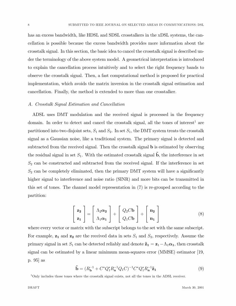
this set of tones. The channel model representation in (7) is re-grouped according to the
partition:
z2z1
= Λ2α2Λ1α1
+ Q2CbQ1Cb
+ n2n1
(8)
where every vector or matrix with the subscript belongs to the set with the same subscript.
For example, z1 and z2 are the received data in sets S1 and S2, respectively. Assume the
primary signal in set S1 can be detected reliably and denote �z1 = z1−Λ1α1, then crosstalksignal can be estimated by a linear minimum mean-squares error (MMSE) estimator [19,
p. 95] as
�b = (R−1b + C∗Q∗1R−1n Q1C)
−1C∗Q∗1R−1n �z1 (9)
1Only includes those tones where the crosstalk signal exists, not all the tones in the ADSL receiver.
DRAFT March 30, 2001
ZENG AND CIOFFI: CROSSTALK CANCELLATION IN XDSL SYSTEMS 9
where Rb and Rn are the signal and noise covariance matrices respectively. The trans-
mitted crosstalk signal sequence b and the background noise are normally assumed to
be white, and the crosstalk signal can be assumed to have unit variance without loss of
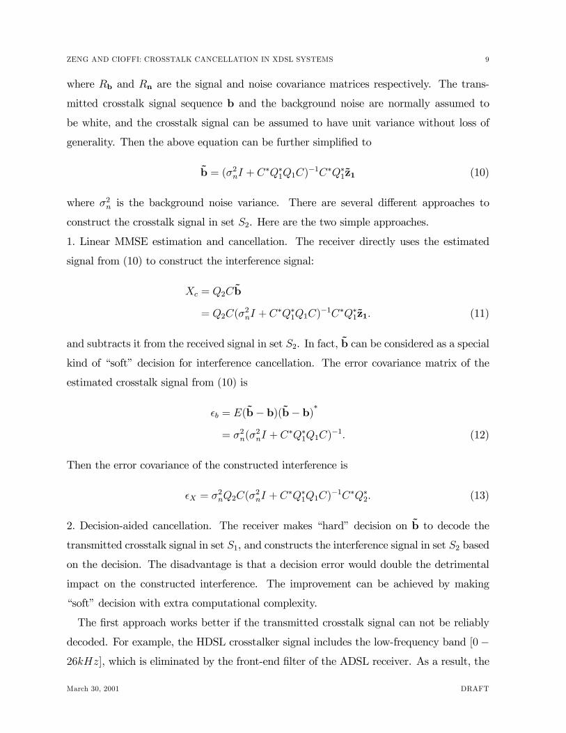
generality. Then the above equation can be further simpliÞed to
�b = (σ2nI + C∗Q∗1Q1C)
−1C∗Q∗1�z1 (10)
where σ2n is the background noise variance. There are several different approaches to
construct the crosstalk signal in set S2. Here are the two simple approaches.
1. Linear MMSE estimation and cancellation. The receiver directly uses the estimated
signal from (10) to construct the interference signal:
Xc = Q2C�b
= Q2C(σ2nI + C
∗Q∗1Q1C)−1C∗Q∗1�z1. (11)
and subtracts it from the received signal in set S2. In fact, �b can be considered as a special
kind of �soft� decision for interference cancellation. The error covariance matrix of the
estimated crosstalk signal from (10) is
²b = E(�b− b)(�b− b)∗
= σ2n(σ2nI + C
∗Q∗1Q1C)−1. (12)
Then the error covariance of the constructed interference is
²X = σ2nQ2C(σ
2nI + C
∗Q∗1Q1C)−1C∗Q∗2. (13)
2. Decision-aided cancellation. The receiver makes �hard� decision on �b to decode the
transmitted crosstalk signal in set S1, and constructs the interference signal in set S2 based
on the decision. The disadvantage is that a decision error would double the detrimental
impact on the constructed interference. The improvement can be achieved by making
�soft� decision with extra computational complexity.
The Þrst approach works better if the transmitted crosstalk signal can not be reliably
decoded. For example, the HDSL crosstalker signal includes the low-frequency band [0−26kHz], which is eliminated by the front-end Þlter of the ADSL receiver. As a result, the
March 30, 2001 DRAFT
10 SUBMITTED TO IEEE JOURNAL ON SELECTED AREAS IN COMMUNICATIONS: DSL
f
||c(f)||2Rb(f)
1/Tc-fo 1/Tcfo
A B
C
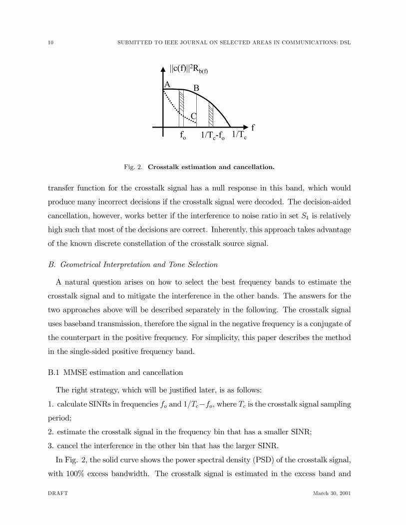
Fig. 2. Crosstalk estimation and cancellation.
transfer function for the crosstalk signal has a null response in this band, which would
produce many incorrect decisions if the crosstalk signal were decoded. The decision-aided
cancellation, however, works better if the interference to noise ratio in set S1 is relatively
high such that most of the decisions are correct. Inherently, this approach takes advantage
of the known discrete constellation of the crosstalk source signal.
B. Geometrical Interpretation and Tone Selection
A natural question arises on how to select the best frequency bands to estimate the
crosstalk signal and to mitigate the interference in the other bands. The answers for the
two approaches above will be described separately in the following. The crosstalk signal
uses baseband transmission, therefore the signal in the negative frequency is a conjugate of
the counterpart in the positive frequency. For simplicity, this paper describes the method
in the single-sided positive frequency band.
B.1 MMSE estimation and cancellation
The right strategy, which will be justiÞed later, is as follows:
1. calculate SINRs in frequencies fo and 1/Tc−fo, where Tc is the crosstalk signal samplingperiod;
2. estimate the crosstalk signal in the frequency bin that has a smaller SINR;
3. cancel the interference in the other bin that has the larger SINR.
In Fig. 2, the solid curve shows the power spectral density (PSD) of the crosstalk signal,
with 100% excess bandwidth. The crosstalk signal is estimated in the excess band and
DRAFT March 30, 2001
ZENG AND CIOFFI: CROSSTALK CANCELLATION IN XDSL SYSTEMS 11
then used to cancel the interference in the main lobe (0, 1/2Tc). The dotted curve AC
shows the residual crosstalk PSD as a result of the crosstalk subtraction. If the smaller
one of the interference to noise ratios in frequencies fo and 1/Tc− fo is denoted by gs (theshaded zone in the Þgure), then the SINR gain in frequency fo is approximately equal to
gs. Similarly, if the crosstalk signal is estimated in the main lobe and used to cancel the
interference in the excess band, the SINR gain in frequency 1/Tc−fo is also approximatelyequal to gs. These statements will be proved later in this subsection.
In fact, the gain is the same no matter which frequency, either fo or 1/Tc − fo, is usedto estimate the crosstalk signal. However, the data rate increase is not the same because
it depends on the original SINR. For example, if the original SINR in frequency 1/Tc− fois −9dB and the gain resulting from crosstalk cancellation is also 9dB, then the capacity
is increased by about 0.5bits/s/Hz; if the original SINR in frequency fo is 10dB and the
gain is the same, then the capacity is increased by about 1.5bits/s/Hz. Therefore, the
crosstalk signal should be estimated in frequency 1/Tc − fo and cancelled in frequencyfo. Otherwise, the data rate improvement is smaller (0.5b/s/Hz versus 1.5b/s/Hz). This
phenomenon could actually happen in an ADSL environment. When the line reach is
very long, the ADSL signal in the excess band is weak compared to the NEXT signal,
therefore, the crosstalk signal should be estimated in the excess band and cancelled in the
main lobe. Correspondingly, if the primary signal has a smaller SINR in the main lobe for
some reason (e.g., because of the bridge tap), the crosstalk signal should be Þrst estimated
in the main lobe and cancelled in the excess band.
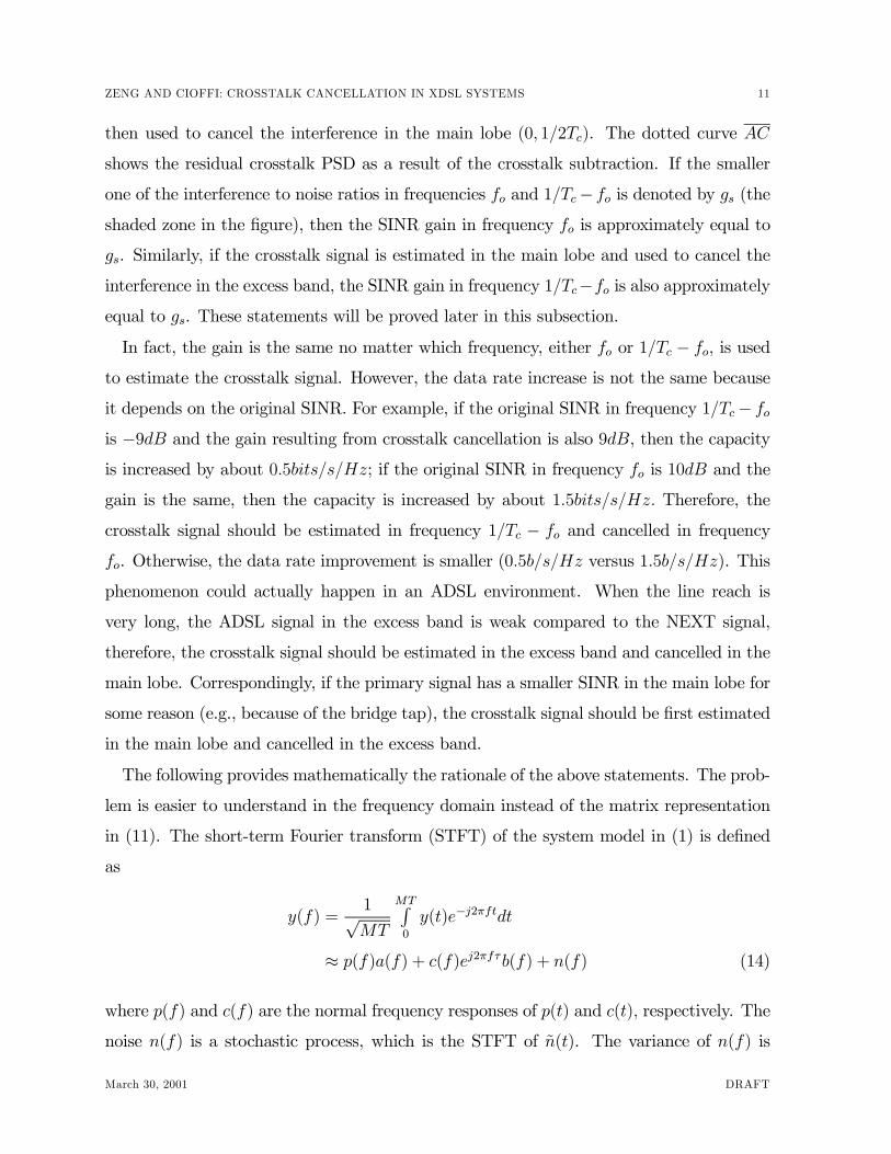
The following provides mathematically the rationale of the above statements. The prob-
lem is easier to understand in the frequency domain instead of the matrix representation
in (11). The short-term Fourier transform (STFT) of the system model in (1) is deÞned
as
y(f) =1√MT
MTR0
y(t)e−j2πftdt
≈ p(f)a(f) + c(f)ej2πfτb(f) + n(f) (14)
where p(f) and c(f) are the normal frequency responses of p(t) and c(t), respectively. The
noise n(f) is a stochastic process, which is the STFT of �n(t). The variance of n(f) is
March 30, 2001 DRAFT
12 SUBMITTED TO IEEE JOURNAL ON SELECTED AREAS IN COMMUNICATIONS: DSL
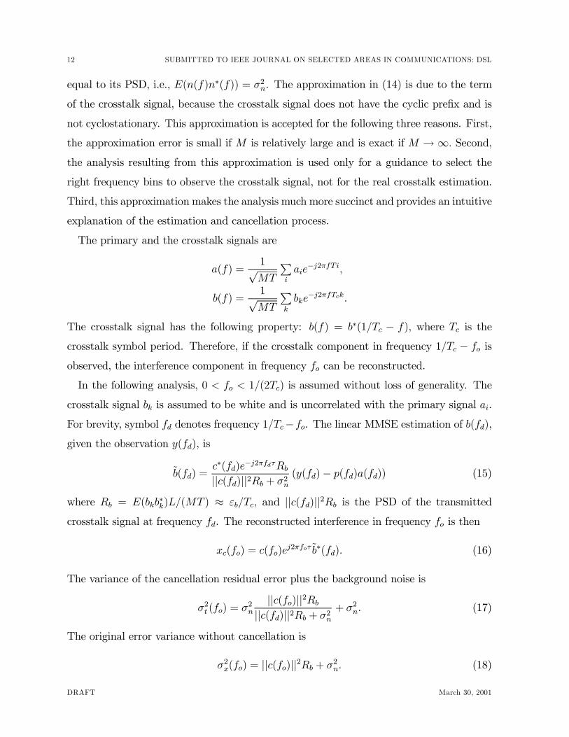
equal to its PSD, i.e., E(n(f)n∗(f)) = σ2n. The approximation in (14) is due to the term
of the crosstalk signal, because the crosstalk signal does not have the cyclic preÞx and is
not cyclostationary. This approximation is accepted for the following three reasons. First,
the approximation error is small if M is relatively large and is exact if M →∞. Second,the analysis resulting from this approximation is used only for a guidance to select the
right frequency bins to observe the crosstalk signal, not for the real crosstalk estimation.
Third, this approximation makes the analysis much more succinct and provides an intuitive
explanation of the estimation and cancellation process.
The primary and the crosstalk signals are
a(f) =1√MT
Pi
aie−j2πfTi,
b(f) =1√MT
Pk
bke−j2πfTck.
The crosstalk signal has the following property: b(f) = b∗(1/Tc − f), where Tc is thecrosstalk symbol period. Therefore, if the crosstalk component in frequency 1/Tc − fo isobserved, the interference component in frequency fo can be reconstructed.
In the following analysis, 0 < fo < 1/(2Tc) is assumed without loss of generality. The
crosstalk signal bk is assumed to be white and is uncorrelated with the primary signal ai.
For brevity, symbol fd denotes frequency 1/Tc−fo. The linear MMSE estimation of b(fd),given the observation y(fd), is
�b(fd) =c∗(fd)e−j2πfdτRb||c(fd)||2Rb + σ2n
(y(fd)− p(fd)a(fd)) (15)
where Rb = E(bkb∗k)L/(MT ) ≈ εb/Tc, and ||c(fd)||2Rb is the PSD of the transmitted
crosstalk signal at frequency fd. The reconstructed interference in frequency fo is then
xc(fo) = c(fo)ej2πfoτ�b∗(fd). (16)
The variance of the cancellation residual error plus the background noise is
σ2t (fo) = σ2n
||c(fo)||2Rb||c(fd)||2Rb + σ2n
+ σ2n. (17)
The original error variance without cancellation is
σ2x(fo) = ||c(fo)||2Rb + σ2n. (18)
DRAFT March 30, 2001
ZENG AND CIOFFI: CROSSTALK CANCELLATION IN XDSL SYSTEMS 13
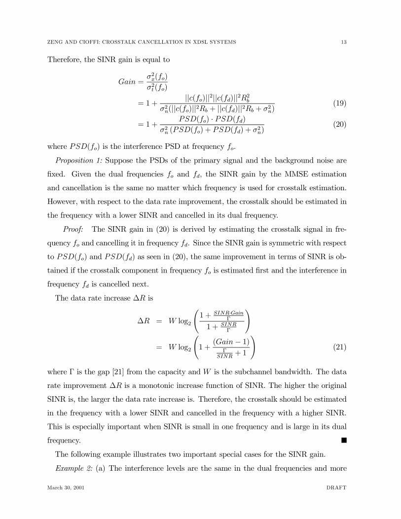
Therefore, the SINR gain is equal to
Gain =σ2x(fo)
σ2t (fo)
= 1 +||c(fo)||2||c(fd)||2R2b
σ2n(||c(fo)||2Rb + ||c(fd)||2Rb + σ2n)(19)
= 1 +PSD(fo) · PSD(fd)
σ2n (PSD(fo) + PSD(fd) + σ2n)
(20)
where PSD(fo) is the interference PSD at frequency fo.
Proposition 1: Suppose the PSDs of the primary signal and the background noise are
Þxed. Given the dual frequencies fo and fd, the SINR gain by the MMSE estimation
and cancellation is the same no matter which frequency is used for crosstalk estimation.
However, with respect to the data rate improvement, the crosstalk should be estimated in
the frequency with a lower SINR and cancelled in its dual frequency.
Proof: The SINR gain in (20) is derived by estimating the crosstalk signal in fre-
quency fo and cancelling it in frequency fd. Since the SINR gain is symmetric with respect
to PSD(fo) and PSD(fd) as seen in (20), the same improvement in terms of SINR is ob-
tained if the crosstalk component in frequency fo is estimated Þrst and the interference in
frequency fd is cancelled next.
The data rate increase ∆R is
∆R = W log2
Ã1 + SINR·Gain
Γ
1 + SINRΓ
!
= W log2
Ã1 +
(Gain− 1)Γ
SINR+ 1
!(21)
where Γ is the gap [21] from the capacity and W is the subchannel bandwidth. The data
rate improvement ∆R is a monotonic increase function of SINR. The higher the original
SINR is, the larger the data rate increase is. Therefore, the crosstalk should be estimated
in the frequency with a lower SINR and cancelled in the frequency with a higher SINR.
This is especially important when SINR is small in one frequency and is large in its dual
frequency.
The following example illustrates two important special cases for the SINR gain.
Example 2: (a) The interference levels are the same in the dual frequencies and more
March 30, 2001 DRAFT
14 SUBMITTED TO IEEE JOURNAL ON SELECTED AREAS IN COMMUNICATIONS: DSL
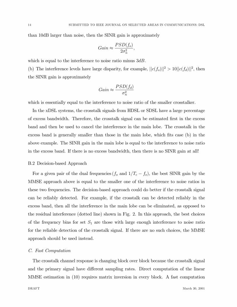
than 10dB larger than noise, then the SINR gain is approximately
Gain ≈ PSD(fo)
2σ2n,
which is equal to the interference to noise ratio minus 3dB.
(b) The interference levels have large disparity, for example, ||c(fo)||2 > 10||c(fd)||2, thenthe SINR gain is approximately
Gain ≈ PSD(fd)
σ2n
which is essentially equal to the interference to noise ratio of the smaller crosstalker.
In the xDSL systems, the crosstalk signals from HDSL or SDSL have a large percentage
of excess bandwidth. Therefore, the crosstalk signal can be estimated Þrst in the excess
band and then be used to cancel the interference in the main lobe. The crosstalk in the
excess band is generally smaller than those in the main lobe, which Þts case (b) in the
above example. The SINR gain in the main lobe is equal to the interference to noise ratio
in the excess band. If there is no excess bandwidth, then there is no SINR gain at all!
B.2 Decision-based Approach
For a given pair of the dual frequencies (fo and 1/Tc − fo), the best SINR gain by theMMSE approach above is equal to the smaller one of the interference to noise ratios in
these two frequencies. The decision-based approach could do better if the crosstalk signal
can be reliably detected. For example, if the crosstalk can be detected reliably in the
excess band, then all the interference in the main lobe can be eliminated, as opposed to
the residual interference (dotted line) shown in Fig. 2. In this approach, the best choices
of the frequency bins for set S1 are those with large enough interference to noise ratio
for the reliable detection of the crosstalk signal. If there are no such choices, the MMSE
approach should be used instead.
C. Fast Computation
The crosstalk channel response is changing block over block because the crosstalk signal
and the primary signal have different sampling rates. Direct computation of the linear
MMSE estimation in (10) requires matrix inversion in every block. A fast computation
DRAFT March 30, 2001
ZENG AND CIOFFI: CROSSTALK CANCELLATION IN XDSL SYSTEMS 15
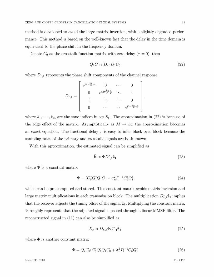
method is developed to avoid the large matrix inversion, with a slightly degraded perfor-
mance. This method is based on the well-known fact that the delay in the time domain is
equivalent to the phase shift in the frequency domain.
Denote C0 as the crosstalk function matrix with zero delay (τ = 0), then
Q1C ≈ Dτ ,1Q1C0 (22)
where Dτ ,1 represents the phase shift components of the channel response,
Dτ ,1 =
ej2π
k1N
τT 0 · · · 0
0 ej2πk2N
τT
. . ....
.... . . . . . 0
0 · · · 0 ej2πkmN
τT
.
where k1, · · · , km are the tone indices in set S1. The approximation in (22) is because ofthe edge effect of the matrix. Asymptotically as M → ∞, the approximation becomesan exact equation. The fractional delay τ is easy to infer block over block because the
sampling rates of the primary and crosstalk signals are both known.
With this approximation, the estimated signal can be simpliÞed as
�b ≈ ΨD∗τ ,1�z1 (23)
where Ψ is a constant matrix
Ψ = (C∗0Q∗1Q1C0 + σ
2nI)
−1C∗0Q∗1 (24)
which can be pre-computed and stored. This constant matrix avoids matrix inversion and
large matrix multiplications in each transmission block. The multiplication D∗τ ,1�z1 implies
that the receiver adjusts the timing offset of the signal �z1. Multiplying the constant matrix
Ψ roughly represents that the adjusted signal is passed through a linear MMSE Þlter. The
reconstructed signal in (11) can also be simpliÞed as
Xc ≈ Dτ ,2ΦD∗τ ,1�z1 (25)
where Φ is another constant matrix
Φ = Q2C0(C∗0Q
∗1Q1C0 + σ
2nI)
−1C∗0Q∗1 (26)
March 30, 2001 DRAFT
16 SUBMITTED TO IEEE JOURNAL ON SELECTED AREAS IN COMMUNICATIONS: DSL
andDτ ,2 is similar toDτ ,1 except that it uses the tone indices of set S2 in the diagonal, e.g.,
ej2πlN
τT , l ∈ S2. Similarly, the computational complexity is reduced dramatically because
the constant matrix Φ can be pre-computed and stored.
D. Extension to Multiple Crosstalkers
The idea of estimating the crosstalk signal in one set of frequency bands and cancelling
it in another set of frequency bands can be extended to more than one crosstalker. The
system model remains the same as (8), but the crosstalk component QCb is modiÞed
slightly to include more crosstalkers, i.e.,
C = [C1, C2, · · · , Ck]b = [b1,b2, · · · ,bk]T
where k is the number of the crosstalkers. The amount of performance improvement
depends on the crosstalkers� characteristics and the choice of the cancellation approaches.
The following example illustrates one particular approach of successive cancellation of the
crosstalk signals by estimating the crosstalk signals in the excess band.
Example 3: The crosstalkers HDSL and SDSL have single-sided bandwidth of 192kHz
and 520kHz. Both of them have about 100% excess bandwidth. Therefore, SDSL can be
estimated Þrst in frequency band [520−1040kHz] where the HDSL crosstalker signal doesnot exist. Then the SDSL crosstalker can be cancelled in the main lobe [138− 520kHz].After that, the same process is used to estimate and cancel the smaller-bandwidth HDSL
crosstalk.
IV. Simulation Results
The ADSL downstream transmission is more vulnerable to NEXT, because the primary
signal attenuates very rapidly while NEXT increases as frequency increases. The simu-
lations are thus concentrated on the downstream receiver on the customer side. In the
current deployment, the strong NEXT mainly comes from ISDN, HDSL, SDSL, T1 or
their repeaters. For a given line, there is very likely only one dominant crosstalk because
of the following two reasons. First, the crosstalk line should reside physically close to the
victim line. Second, most services in the same bundle are deployed with ADSL. With the
DRAFT March 30, 2001
ZENG AND CIOFFI: CROSSTALK CANCELLATION IN XDSL SYSTEMS 17
xDSL ADSL HDSL
Line code DMT 2B1Q
Sampling rate
fo (ks/ sec)2208 392
Power (dBm) 19.0 13.6
Duplexingup : 26− 138kHz
down : 138− 1104kHzDual
TABLE I
Main ADSL and HDSL Characteristics.
above two justiÞcations, the simulations assume only one NEXT for a given line.
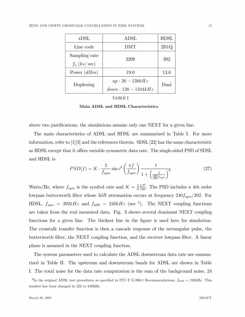
The main characteristics of ADSL and HDSL are summarized in Table I. For more
information, refer to [1][3] and the references therein. SDSL [22] has the same characteristic
as HDSL except that it offers variable symmetric data rate. The single-sided PSD of SDSL
and HDSL is
PSD(f) = K · 2
fsymsin c2
µπf
fsym
¶1
1 +³
f240392
fsym
´8 (27)
Watts/Hz, where fsym is the symbol rate and K = 592.72
135. The PSD includes a 4th order
lowpass butterworth Þlter whose 3dB attenuation occurs at frequency 240fsym/392. For
HDSL, fsym = 392kHz and f3dB = 240kHz (see 2). The NEXT coupling functions
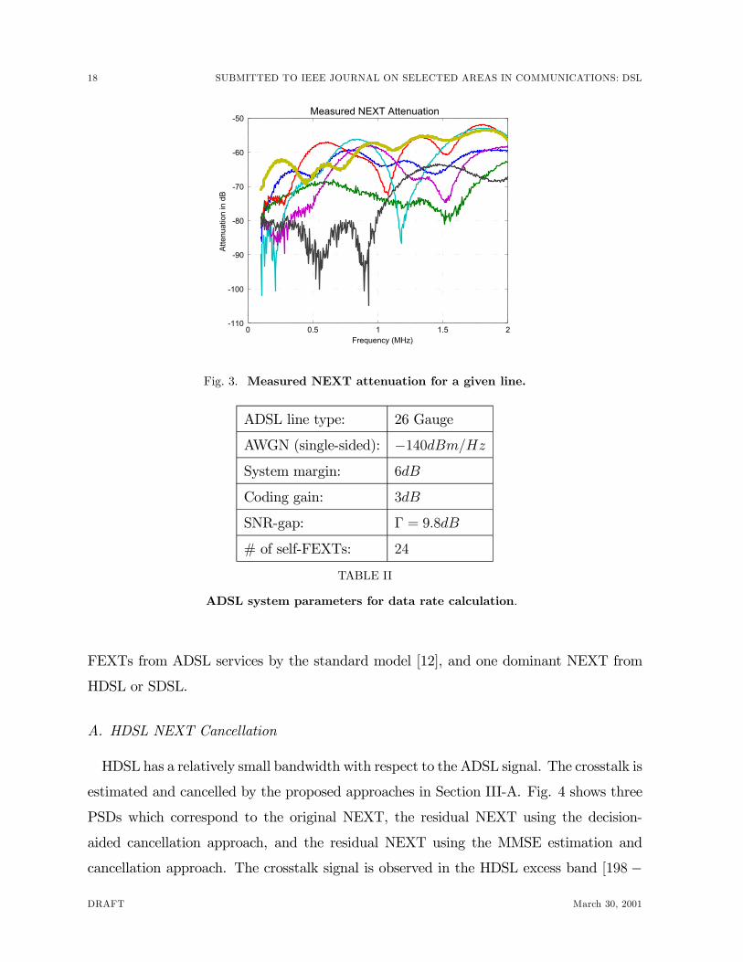
are taken from the real measured data. Fig. 3 shows several dominant NEXT coupling
functions for a given line. The thickest line in the Þgure is used here for simulation.
The crosstalk transfer function is then a cascade response of the rectangular pulse, the
butterworth Þlter, the NEXT coupling function, and the receiver lowpass Þlter. A linear
phase is assumed in the NEXT coupling function.
The system parameters used to calculate the ADSL downstream data rate are summa-
rized in Table II. The upstream and downstream bands for ADSL are shown in Table
I. The total noise for the data rate computation is the sum of the background noise, 24
2In the original ADSL test procedures as speciÞed in ITU-T G.996.1 Recommendations, f3dB = 192kHz. This
number has been changed in [22] to 240kHz.
March 30, 2001 DRAFT
18 SUBMITTED TO IEEE JOURNAL ON SELECTED AREAS IN COMMUNICATIONS: DSL
0 0.5 1 1.5 2-110
-100
-90
-80
-70
-60
-50Measured NEXT Attenuation
Frequency (MHz)
Atte
nuat
ion
in d
B
Fig. 3. Measured NEXT attenuation for a given line.
ADSL line type: 26 Gauge
AWGN (single-sided): −140dBm/HzSystem margin: 6dB
Coding gain: 3dB
SNR-gap: Γ = 9.8dB
# of self-FEXTs: 24
TABLE II
ADSL system parameters for data rate calculation.
FEXTs from ADSL services by the standard model [12], and one dominant NEXT from
HDSL or SDSL.
A. HDSL NEXT Cancellation
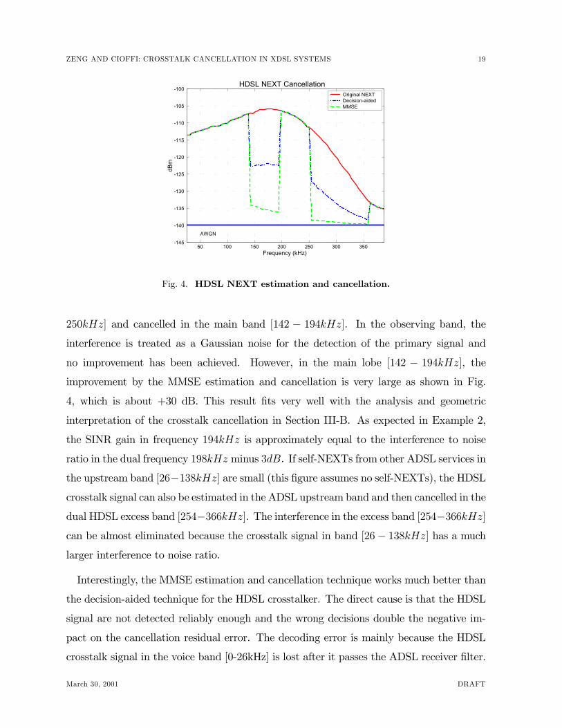
HDSL has a relatively small bandwidth with respect to the ADSL signal. The crosstalk is
estimated and cancelled by the proposed approaches in Section III-A. Fig. 4 shows three
PSDs which correspond to the original NEXT, the residual NEXT using the decision-
aided cancellation approach, and the residual NEXT using the MMSE estimation and
cancellation approach. The crosstalk signal is observed in the HDSL excess band [198−
DRAFT March 30, 2001
ZENG AND CIOFFI: CROSSTALK CANCELLATION IN XDSL SYSTEMS 19
50 100 150 200 250 300 350-145
-140
-135
-130
-125
-120
-115
-110
-105
-100
Frequency (kHz)
dBm
HDSL NEXT Cancellation
AWGN
Original NEXT Decision-aidedMMSE
Fig. 4. HDSL NEXT estimation and cancellation.
250kHz] and cancelled in the main band [142 − 194kHz]. In the observing band, theinterference is treated as a Gaussian noise for the detection of the primary signal and
no improvement has been achieved. However, in the main lobe [142 − 194kHz], theimprovement by the MMSE estimation and cancellation is very large as shown in Fig.
4, which is about +30 dB. This result Þts very well with the analysis and geometric
interpretation of the crosstalk cancellation in Section III-B. As expected in Example 2,
the SINR gain in frequency 194kHz is approximately equal to the interference to noise
ratio in the dual frequency 198kHz minus 3dB. If self-NEXTs from other ADSL services in
the upstream band [26−138kHz] are small (this Þgure assumes no self-NEXTs), the HDSLcrosstalk signal can also be estimated in the ADSL upstream band and then cancelled in the
dual HDSL excess band [254−366kHz]. The interference in the excess band [254−366kHz]can be almost eliminated because the crosstalk signal in band [26− 138kHz] has a muchlarger interference to noise ratio.
Interestingly, the MMSE estimation and cancellation technique works much better than
the decision-aided technique for the HDSL crosstalker. The direct cause is that the HDSL
signal are not detected reliably enough and the wrong decisions double the negative im-
pact on the cancellation residual error. The decoding error is mainly because the HDSL
crosstalk signal in the voice band [0-26kHz] is lost after it passes the ADSL receiver Þlter.
March 30, 2001 DRAFT
20 SUBMITTED TO IEEE JOURNAL ON SELECTED AREAS IN COMMUNICATIONS: DSL
3000 3500 4000 4500 5000 5500 60000
1
2
3
4
5
6
Loop Length (m)
Mbp
s
ADSL Downstream Data Rate
Without cancellationWith cancellation
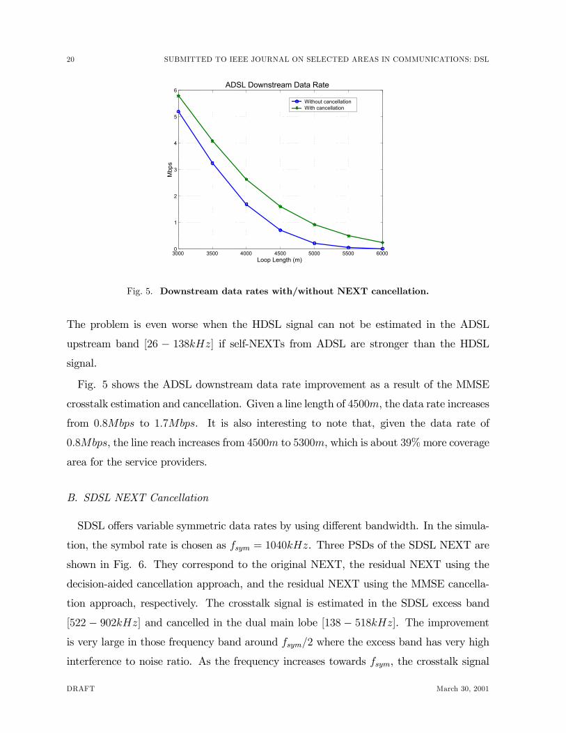
Fig. 5. Downstream data rates with/without NEXT cancellation.
The problem is even worse when the HDSL signal can not be estimated in the ADSL
upstream band [26 − 138kHz] if self-NEXTs from ADSL are stronger than the HDSL
signal.
Fig. 5 shows the ADSL downstream data rate improvement as a result of the MMSE
crosstalk estimation and cancellation. Given a line length of 4500m, the data rate increases
from 0.8Mbps to 1.7Mbps. It is also interesting to note that, given the data rate of
0.8Mbps, the line reach increases from 4500m to 5300m, which is about 39%more coverage
area for the service providers.
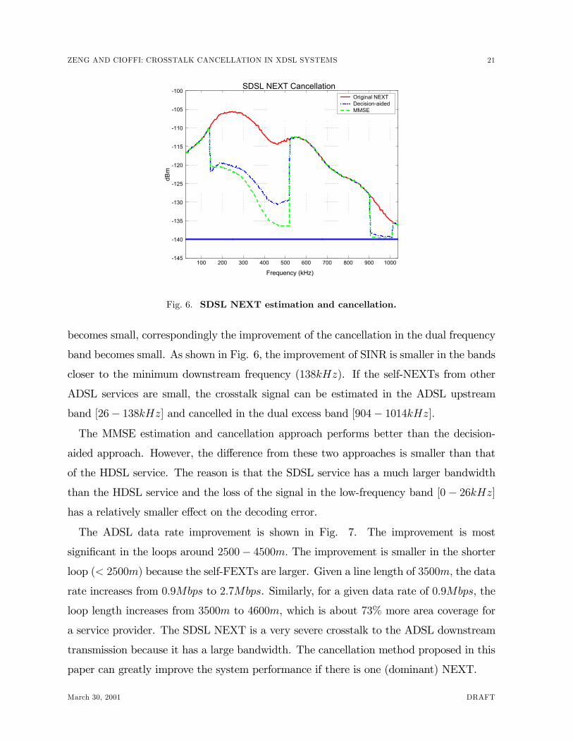
B. SDSL NEXT Cancellation
SDSL offers variable symmetric data rates by using different bandwidth. In the simula-
tion, the symbol rate is chosen as fsym = 1040kHz. Three PSDs of the SDSL NEXT are
shown in Fig. 6. They correspond to the original NEXT, the residual NEXT using the
decision-aided cancellation approach, and the residual NEXT using the MMSE cancella-
tion approach, respectively. The crosstalk signal is estimated in the SDSL excess band
[522 − 902kHz] and cancelled in the dual main lobe [138 − 518kHz]. The improvementis very large in those frequency band around fsym/2 where the excess band has very high
interference to noise ratio. As the frequency increases towards fsym, the crosstalk signal
DRAFT March 30, 2001
ZENG AND CIOFFI: CROSSTALK CANCELLATION IN XDSL SYSTEMS 21
100 200 300 400 500 600 700 800 900 1000-145
-140
-135
-130
-125
-120
-115
-110
-105
-100
Frequency (kHz)
dBm
SDSL NEXT CancellationOriginal NEXT Decision-aidedMMSE
Fig. 6. SDSL NEXT estimation and cancellation.
becomes small, correspondingly the improvement of the cancellation in the dual frequency
band becomes small. As shown in Fig. 6, the improvement of SINR is smaller in the bands
closer to the minimum downstream frequency (138kHz). If the self-NEXTs from other
ADSL services are small, the crosstalk signal can be estimated in the ADSL upstream
band [26− 138kHz] and cancelled in the dual excess band [904− 1014kHz].The MMSE estimation and cancellation approach performs better than the decision-
aided approach. However, the difference from these two approaches is smaller than that
of the HDSL service. The reason is that the SDSL service has a much larger bandwidth
than the HDSL service and the loss of the signal in the low-frequency band [0 − 26kHz]has a relatively smaller effect on the decoding error.
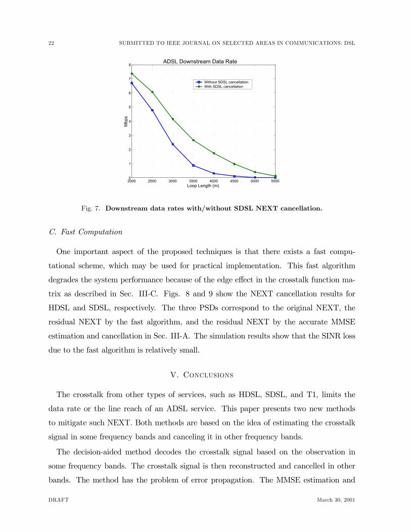
The ADSL data rate improvement is shown in Fig. 7. The improvement is most
signiÞcant in the loops around 2500− 4500m. The improvement is smaller in the shorterloop (< 2500m) because the self-FEXTs are larger. Given a line length of 3500m, the data
rate increases from 0.9Mbps to 2.7Mbps. Similarly, for a given data rate of 0.9Mbps, the
loop length increases from 3500m to 4600m, which is about 73% more area coverage for
a service provider. The SDSL NEXT is a very severe crosstalk to the ADSL downstream
transmission because it has a large bandwidth. The cancellation method proposed in this
paper can greatly improve the system performance if there is one (dominant) NEXT.
March 30, 2001 DRAFT
22 SUBMITTED TO IEEE JOURNAL ON SELECTED AREAS IN COMMUNICATIONS: DSL
2000 2500 3000 3500 4000 4500 5000 55000
1
2
3
4
5
6
7
8
Loop Length (m)
Mbp
s
ADSL Downstream Data Rate
Without SDSL cancellationWith SDSL cancellation
Fig. 7. Downstream data rates with/without SDSL NEXT cancellation.
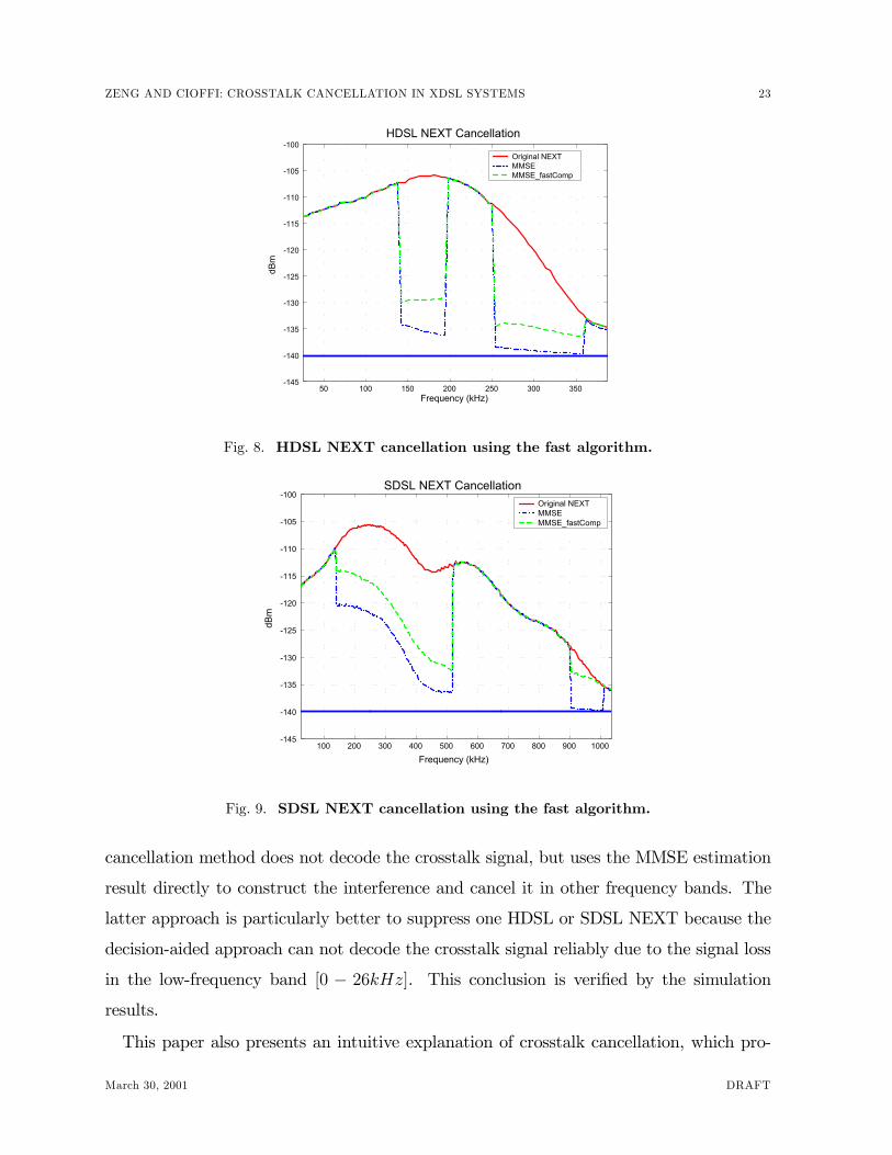
C. Fast Computation
One important aspect of the proposed techniques is that there exists a fast compu-
tational scheme, which may be used for practical implementation. This fast algorithm
degrades the system performance because of the edge effect in the crosstalk function ma-
trix as described in Sec. III-C. Figs. 8 and 9 show the NEXT cancellation results for
HDSL and SDSL, respectively. The three PSDs correspond to the original NEXT, the
residual NEXT by the fast algorithm, and the residual NEXT by the accurate MMSE
estimation and cancellation in Sec. III-A. The simulation results show that the SINR loss
due to the fast algorithm is relatively small.
V. Conclusions
The crosstalk from other types of services, such as HDSL, SDSL, and T1, limits the
data rate or the line reach of an ADSL service. This paper presents two new methods
to mitigate such NEXT. Both methods are based on the idea of estimating the crosstalk
signal in some frequency bands and canceling it in other frequency bands.
The decision-aided method decodes the crosstalk signal based on the observation in
some frequency bands. The crosstalk signal is then reconstructed and cancelled in other
bands. The method has the problem of error propagation. The MMSE estimation and
DRAFT March 30, 2001
ZENG AND CIOFFI: CROSSTALK CANCELLATION IN XDSL SYSTEMS 23
50 100 150 200 250 300 350-145
-140
-135
-130
-125
-120
-115
-110
-105
-100
Frequency (kHz)
dBm
HDSL NEXT Cancellation
Original NEXT MMSE MMSE_fastComp
Fig. 8. HDSL NEXT cancellation using the fast algorithm.
100 200 300 400 500 600 700 800 900 1000-145
-140
-135
-130
-125
-120
-115
-110
-105
-100
Frequency (kHz)
dBm
SDSL NEXT CancellationOriginal NEXT MMSE MMSE_fastComp
Fig. 9. SDSL NEXT cancellation using the fast algorithm.
cancellation method does not decode the crosstalk signal, but uses the MMSE estimation
result directly to construct the interference and cancel it in other frequency bands. The
latter approach is particularly better to suppress one HDSL or SDSL NEXT because the
decision-aided approach can not decode the crosstalk signal reliably due to the signal loss
in the low-frequency band [0 − 26kHz]. This conclusion is veriÞed by the simulationresults.
This paper also presents an intuitive explanation of crosstalk cancellation, which pro-
March 30, 2001 DRAFT
24 SUBMITTED TO IEEE JOURNAL ON SELECTED AREAS IN COMMUNICATIONS: DSL
vides the guidance to select the right frequency bands to estimate the crosstalk signal. One
interesting result of the MMSE estimation and cancellation is that the gain of interference
suppression is the same no matter the crosstalk signal is estimated in the main lobe or in
the excess band. In general, the main lobe has larger interference than the excess band.
Therefore, if the crosstalk signal is estimated in the main lobe, the interference caused by
the excess band can be eliminated. Conversely, if the crosstalk signal is estimated in the
excess band, the SINR gain in the main lobe is equal to the interference to noise ratio in
the excess band. The larger the interference in the excess band, the better the suppression
of the interference in the main lobe.
Moreover, a fast computational algorithm is developed for practical implementation with
slightly degraded performance. This method avoids matrix inversion and large matrix
multiplication in every transmission block. In contrast, the traditional MMSE estimation
requires high computational complexity since the crosstalk signal is non-stationary and
large matrix inversion is need in every transmission block.
In conclusion, the MMSE estimation and cancellation scheme is very effective in can-
celling the crosstalk if the crosstalk has a large percentage of excess bandwidth. In current
xDSL systems, NEXT to an ADSL receiver has a large excess bandwidth, this method is
very effective to cancel one dominant NEXT.
References
[1] T. Starr, J. M. Cioffi, and P. Silverman, �Understanding Digital Subscriber Line Technology�, Prentice Hall,
1998.
[2] J. W. Cook, et. al., �The Noise and Crosstalk Environment for ADSL and VDSL systems�, IEEE Commu-
nications Magazine, May 1999, p. 73-78.
[3] ITU Recommendation G.995.1, �Overview of Digital Subscriber Line (DSL) Recommendations�, Jun. 1999.
[4] Felix Tarkoy, �Iterative Multi-user Decoding for Asynchronous Users�, International Symposium on Informa-
tion Theory, 1997, p. 30.
[5] Michael Moher, �An Iterative Multiuser Decoder for Asynchronous BPSK Users�, International Symposium
on Information Theory, 1998, p. 423.
[6] J. M. Cioffi, et. al., �Rejection of Home LAN NEXT in VDSL via Soft Cancellation�, ETSI TM6 Standard
Contributions TD15, Edinburgh, Sep. 20-24, 1999.
[7] K. Cheong, �Multiuser Detection for DSL Applications�, Stanford Ph.D. Thesis, 2000.
[8] J. A. C. Bingham, �RFI Suppression in Multicarrier Systems�, Globecom, vol. 2, Nov. 96, p. 1026-1030.
[9] B. Wiese and J. A. C. Bingham, �Digital Radio Frequency Cancellation for DMT VDSL�, T1E1.4/97-460,
Dec. 1997.
DRAFT March 30, 2001
ZENG AND CIOFFI: CROSSTALK CANCELLATION IN XDSL SYSTEMS 25
[10] B. R. Petersen and D. D. Falconer, �Minimum Mean Square Equalization in Cyclostationary and Stationary
Interference-Analysis and Subscriber Line Calculations�, IEEE Journal on Selected Areas in Communications,
Vol. 9, No. 6, Aug. 1991, p. 931-940.
[11] M. Abdulrahman and D. D. Falconer, �Cyclostationary Crosstalk Suppression by Decision Feedback Equal-
ization on Digital Subscriber Loops�, IEEE Journal on Selected Areas in Communications, Vol. 10, No. 3,
Apr. 1992, p. 640-649.
[12] ITU Recommendations G.992.1, �Asymmetric Digital Subscriber Line (DSL) Transceivers�, Jun. 1999.
[13] I. Kalet, �The Multitone Channel�, IEEE Transactions on Communications, Vol. 37, No. 2, Feb. 1989, p.
119-124.
[14] A. Ruiz, J. M. Cioffi, and S. Kasturia, �Discrete Multiple Tone Modulation with Coset Coding for the
Spectrally Shaped Channel�, IEEE Transactions on Communications, Vol. 40, No. 6, Jun. 1992, p. 1012-
1029.
[15] M. L. Doelz, E. T. Heald, and D. L. Martin, �Binary Data Transmission Techniques for Linear System�,
Proceedings of IRE, May 1957, p. 656-661.
[16] J. A. C. Bingham, �Multicarrier Modulation for Data Transmission : an Idea Whose Time Has Come�, IEEE
Communications Magazine, May 1990, p. 5-14.
[17] J. A. C. Bingham, �ADSL, VDSL, and Multicarrier Modulation�, John Wiley & Sons, Inc., 2000.
[18] G. H. Golub and C. F. Van Loan, �Matrix Computation�, The John Hopkins University Press, 1996.
[19] T. Kailath, A. H. Sayed, and B. Hassibi, �Linear Estimation�, Prentice Hall, 1999.
[20] C. H. Zeng, C. Aldana, A. Salvekar, and J. M. Cioffi, �Crosstalk IdentiÞcation in xDSL Systems�, to appear
in IEEE Journal on Selected Areas in Communications: Special Issue on Multiuser Detection.
[21] G. D. Forney Jr. and M. V. Eyuboglu, �Combined Equalization and Coding using Precoding�, IEEE Com-
munications Magazine, Dec. 1991, p.25-34.
[22] ANSI T1.417, �Spectrum Management for Loop Transmission Systems�, Draft T1E1.4/2000-002R6, Nov. 28,
2000.
March 30, 2001 DRAFT