Embed Size (px)
Citation preview
IEC 61174 Edition 4.0 2015-08
REDLINE VERSION
Maritime navigation and radiocommunication equipment and systems – Electronic chart display and information system (ECDIS) – Operational and performance requirements, methods of testing and required test results
INTERNATIONAL ELECTROTECHNICAL COMMISSION
ICS 47.020.70
ISBN 978-2-8322-2865-4
® Registered trademark of the International Electrotechnical Commission
®
Warning! Make sure that you obtained this publication from an authorized distributor.
colourinside
This is a preview - click here to buy the full publication
– 2 – IEC 61174:2015 RLV © IEC 2015
CONTENTS
FOREWORD ......................................................................................................................... 12 1 Scope ............................................................................................................................ 14 2 Normative references .................................................................................................... 14 3 Terms, definitions and abbreviations ............................................................................. 16
3.1 Terms and definitions............................................................................................ 16 3.2 Abbreviations ........................................................................................................ 22
4 Minimum operational and performance requirements ..................................................... 23 4.1 General ................................................................................................................. 23 4.2 ECDIS definitions .................................................................................................. 24 4.3 Display of SENC information ................................................................................. 24
4.3.1 SENC .......................................................................................................... 24 4.3.2 Warning Indication about use of non-HO source .......................................... 24 4.3.3 Categories of display ................................................................................... 24 4.3.4 Safety contour ............................................................................................. 26 4.3.5 Safety depth ................................................................................................ 26 4.3.6 Information content ...................................................................................... 26 4.3.7 Verification and updates .............................................................................. 26 4.3.8 Information about chart objects .................................................................... 26 4.3.9 Display scale ............................................................................................... 26
4.4 Provision and updating of chart information .......................................................... 26 4.4.1 Contents of the SENC .................................................................................. 26 4.4.2 Updates ....................................................................................................... 27
4.5 Scale .................................................................................................................... 28 4.6 Display of other navigational information ............................................................... 28
4.6.1 Common refrence system General for all overlays ....................................... 28 4.6.2 Radar and plotting information ..................................................................... 28 4.6.3 AIS information ............................................................................................ 31 4.6.4 AIS target data ............................................................................................ 34 4.6.5 AIS voyage-related data .............................................................................. 34 4.6.6 AIS CPA/TCPA alarms ................................................................................. 35 4.6.7 AIS lost target warning ................................................................................. 35 4.6.8 Anchor watch ............................................................................................... 36
4.7 Display mode and generation of the neighbouring area ......................................... 36 4.8 Colours and symbols ............................................................................................ 37 4.9 Display requirements ............................................................................................ 37
4.9.1 Route planning and monitoring .................................................................... 37 4.9.2 Chart presentation size ................................................................................ 37 4.9.3 Colour and resolution ................................................................................... 37 4.9.4 Presentation ................................................................................................ 38 4.9.5 Removal of information categories ............................................................... 38
4.10 Route planning, monitoring and voyage recording ................................................. 38 4.10.1 General ....................................................................................................... 38 4.10.2 Route planning ............................................................................................ 38 4.10.3 Route monitoring ......................................................................................... 40 4.10.4 Position integration ...................................................................................... 42 4.10.5 Object information ....................................................................................... 42
This is a preview - click here to buy the full publication
IEC 61174:2015 RLV © IEC 2015 – 3 –
4.10.6 LOP position fix ........................................................................................... 42 4.10.7 Voyage recording ......................................................................................... 43
4.11 Calculations and accuracy .................................................................................... 43 4.12 Connections with other equipment (interfaces) ...................................................... 44
4.12.1 Connection with navigation equipment ......................................................... 44 4.12.2 Connection with BAM ................................................................................... 44 4.12.3 Connection with VDR ................................................................................... 45 4.12.4 Connection with BNWAS .............................................................................. 46 4.12.5 Connection for SENC information ................................................................ 46 4.12.6 Connection with NAVTEX or SafetyNET for MSI .......................................... 46 4.12.7 Connection for transfer of route information ................................................. 47 4.12.8 Connection with INS .................................................................................... 47
4.13 Performance tests, malfunction alarms alerts and indications ............................... 47 4.14 Back-up arrangements .......................................................................................... 48 4.15 Power supply ........................................................................................................ 48 4.16 Software maintenance .......................................................................................... 48 4.17 Quality management requirements ........................................................................ 48 4.18 Default control setting and saved user control settings .......................................... 49
5 Requirements contained in IHO special publications ...................................................... 52 5.1 Content and structure of chart data ........................................................................... 5.1 Priority of chart display ......................................................................................... 52 5.2 Display of chart information .................................................................................. 52
5.2.1 Scale and navigation purpose ...................................................................... 52 5.2.2 Text ................................................................................................................. 5.2.2 Units and legend .......................................................................................... 53 5.2.3 Terminology ................................................................................................. 54
5.3 Display functions .................................................................................................. 54 5.3.1 Object information Cursor pick ..................................................................... 54 5.3.2 Navigational information .............................................................................. 55 5.3.2 Safety contour ................................................................................................. 5.3.3 Navigational calculations ................................................................................. 5.3.3 Date-dependant ENC objects ....................................................................... 55
5.4 Supplementary display functions ........................................................................... 56 5.4.1 Additional mariner’s information ................................................................... 56 5.4.2 Additional non-HO information ..................................................................... 56 5.4.3 Tidal adjustment .......................................................................................... 57
5.5 Use of the presentation library .............................................................................. 57 5.5.1 Presentation library ...................................................................................... 57 5.5.2 Test diagrams .............................................................................................. 58
5.6 Display characteristics .......................................................................................... 58 5.6.1 Display base .................................................................................................... 5.6.2 Navigators notes ..............................................................................................
5.7 Performance requirements .................................................................................... 58 5.7.1 Redraw ........................................................................................................ 58 5.7.2 Resolution ................................................................................................... 59 5.7.3 Symbols ....................................................................................................... 59 5.7.4 Number of colours ....................................................................................... 59 5.7.5 Brightness and contrast ............................................................................... 59
5.8 Ergonomic requirements ....................................................................................... 60
This is a preview - click here to buy the full publication
– 4 – IEC 61174:2015 RLV © IEC 2015
5.8.1 Mode and orientation ................................................................................... 60 5.8.2 Windows ...................................................................................................... 60 5.8.3 Mariner’s information panel ..............................................................................
5.9 Update of chart information ................................................................................... 60 5.9.1 General ....................................................................................................... 60 5.9.2 Manual update ............................................................................................. 62 5.9.3 Semi-automatic update ................................................................................ 63 5.9.4 Reception of updates ................................................................................... 63 5.9.5 Sequence check .......................................................................................... 63 5.9.6 Consistency check ....................................................................................... 63 5.9.7 Geographic applicability ............................................................................... 64 5.9.8 Summary report ........................................................................................... 64 5.9.9 Review of ENC updates ............................................................................... 64 5.9.10 Modification of updates ................................................................................ 64
5.10 Operational area ................................................................................................... 64 5.11 External removable media ..................................................................................... 65
6 Methods of testing and required test results .................................................................. 65 6.1 EUT installation, technical documentation, and test requirements ......................... 65 6.2 Interfaces.............................................................................................................. 65
6.2.1 General ....................................................................................................... 65 6.2.2 BAM interface .............................................................................................. 66 6.2.3 VDR interface .............................................................................................. 67 6.2.4 BNWAS interface ......................................................................................... 68
6.3 General requirements and presentation requirements ........................................... 68 6.3.1 General requirements .................................................................................. 68 6.3.2 Presentation requirements ........................................................................... 68
6.4 Preparation ........................................................................................................... 69 6.4.1 Power-up ..................................................................................................... 69 6.4.2 Initial ship parameters ................................................................................. 69 6.4.3 Required test items ...................................................................................... 69
6.5 Initial data tests Requirements related to ENC chart ............................................. 70 6.5.1 General ....................................................................................................... 70 6.5.2 Presentation library ...................................................................................... 71 6.5.3 ENC ............................................................................................................. 71 6.5.4 Encrypted ENC ............................................................................................ 71
6.6 Accuracy ............................................................................................................... 72 6.7 Visual requirements .............................................................................................. 72
6.7.1 Symbols ....................................................................................................... 72 6.7.2 Terminology, units and legend ..................................................................... 73 6.7.3 Colour table ................................................................................................. 73 6.7.4 Resolution ................................................................................................... 74 6.7.5 Display characteristics ................................................................................. 74
6.8 Functional requirements........................................................................................ 74 6.8.1 Methods of testing ....................................................................................... 74 6.8.2 Standard display .......................................................................................... 75 6.8.3 Display base ................................................................................................ 75 6.8.4 All other information ..................................................................................... 75 6.8.5 Viewing group layers and text group layers .................................................. 75 6.8.6 Display priorities .......................................................................................... 76
This is a preview - click here to buy the full publication
IEC 61174:2015 RLV © IEC 2015 – 5 –
6.8.7 Additional display functions.......................................................................... 76 6.8.8 Scale and navigation purpose ...................................................................... 77 6.8.9 Mode and orientation ................................................................................... 77 6.8.10 Safety contour ............................................................................................. 78 6.8.11 Safety depth ................................................................................................ 78 6.8.12 Object information Cursor pick ..................................................................... 80 6.8.13 Navigation related functions ......................................................................... 81 6.8.14 Position integration ...................................................................................... 81 6.8.15 Radar and plotting other navigational information ........................................ 81 6.8.16 Loading of corrupted data ............................................................................ 84 6.8.17 Automatic updates ....................................................................................... 84 6.8.18 Manual updates ........................................................................................... 86 6.8.19 Self-tests of major functions......................................................................... 86 6.8.20 Operational area .......................................................................................... 87 6.8.21 External removable media ........................................................................... 88
6.9 Operational requirements ...................................................................................... 88 6.9.1 Ergonomic principles ................................................................................... 88 6.9.2 Route planning ............................................................................................ 88 6.9.3 Route monitoring ......................................................................................... 90 6.9.4 Twelve-hour log ........................................................................................... 91 6.9.5 Voyage record ............................................................................................. 92 6.9.6 Power supply ............................................................................................... 92 6.9.7 LOP position fix ........................................................................................... 92
6.10 Software maintenance .......................................................................................... 93 6.11 Quality management ............................................................................................. 93 6.12 Default control setting and saved operator control settings ................................... 93 6.13 AIS information and AIS target data ...................................................................... 94
6.13.1 General ....................................................................................................... 94 6.13.2 AIS targets and data report capacity ............................................................ 94 6.13.3 AIS target filtering ........................................................................................ 94 6.13.4 Activation and deactivation of AIS targets .................................................... 95 6.13.5 AIS functionality and presentation ................................................................ 95 6.13.6 AIS target data ............................................................................................ 96 6.13.7 AIS CPA/TCPA alarm .................................................................................. 97 6.13.8 AIS lost target warning ................................................................................. 97
6.14 AIS Voyage-related data ....................................................................................... 98 6.15 Anchor watch ........................................................................................................ 98 6.16 NAVTEX and SafetyNET for MSI ........................................................................... 98 6.17 Interface for transfer of route information .............................................................. 99 6.18 Interface with INS ............................................................................................... 100
Annex A (normative) SENC information to be displayed during route planning and route monitoring .................................................................................................................. 101 Annex B (normative) Navigational elements and parameters .............................................. 102 Annex C (normative) Areas for which special conditions exist ............................................ 103 Annex D (normative) Alarms and indicators Alerts and indications ..................................... 104 Annex E (normative) ENC test data set Mandatory terminology and abbreviations ............. 109 Annex F (normative) Back-up arrangements ...................................................................... 115
F.1 Introduction Overview ......................................................................................... 115
This is a preview - click here to buy the full publication
– 6 – IEC 61174:2015 RLV © IEC 2015
F.2 Purpose .............................................................................................................. 115 F.3 Functional requirements...................................................................................... 115
F.3.1 Required functions and their availability ..................................................... 115 F.3.2 Reliability and accuracy ............................................................................. 119 F.3.3 Malfunctions, warnings, alarms alerts and indications ................................ 119
F.4 Operational requirements .................................................................................... 119 F.4.1 Ergonomics ................................................................................................ 119 F.4.2 Presentation of information ........................................................................ 119
F.5 Power supply ...................................................................................................... 120 F.6 Connections with other equipment Other requirement ......................................... 120
F.6.1 Back-up Connection with other systems ..................................................... 120 F.6.2 Route transfer interface ............................................................................. 121 F.6.3 Radar as back-up system .......................................................................... 121 F.6.4 Operational area ........................................................................................ 121 F.6.5 Software maintenance ............................................................................... 122 F.6.6 Quality management .................................................................................. 122 F.6.7 Default Control Settings and Saved User Control Settings ......................... 122 F.6.8 External removable media ......................................................................... 122
F.7 Methods of testing and required test results ........................................................ 122 F.7.1 EUT installation and technical documentation ............................................ 122 F.7.2 Interfaces .................................................................................................. 122 F.7.3 General requirements and presentation requirements ............................... 122 F.7.4 Preparation ................................................................................................ 122 F.7.5 Initial data tests – Chart ............................................................................. 123 F.7.6 Accuracy .................................................................................................... 123 F.7.7 Visual requirements ................................................................................... 124 F.7.8 Functional requirements ............................................................................ 124 F.7.9 Operational requirements ........................................................................... 126
Annex G (normative) ECDIS in the RCDS mode of operation ............................................. 130 G.1 Introduction Overview ......................................................................................... 130 G.2 RCDS definitions ................................................................................................ 130 G.3 Display of SRNC information ............................................................................... 131
G.3.1 SRNC ........................................................................................................ 131 G.3.2 Categories of display ................................................................................. 131 G.3.3 Power failure ............................................................................................. 131 G.3.4 Information content .................................................................................... 131 G.3.5 Verification and updates ............................................................................ 131 G.3.6 Indication ................................................................................................... 132
G.4 Provision and updating of chart information ........................................................ 132 G.4.1 Contents of the RNC .................................................................................. 132 G.4.2 Updates ..................................................................................................... 132
G.5 Scale .................................................................................................................. 133 G.6 Display of other navigational information ............................................................. 133
G.6.1 Common reference system General for all overlays ................................... 133 G.6.2 Radar and plotting information ................................................................... 133 G.6.3 AS information ........................................................................................... 134 G.6.4 AIS Target Data ......................................................................................... 134 G.6.5 AIS Voyage Related Data .......................................................................... 134 G.6.6 AIS CPA/TCPA alarms ............................................................................... 134
This is a preview - click here to buy the full publication
IEC 61174:2015 RLV © IEC 2015 – 7 –
G.6.7 AIS lost target warning ............................................................................... 134 G.6.8 Anchor watch ............................................................................................. 134
G.7 Display mode and generation of the neighbouring area ....................................... 134 G.8 Colours and symbols .......................................................................................... 135 G.9 Display requirements .......................................................................................... 135
G.9.1 Route planning and monitoring .................................................................. 135 G.9.2 Display characteristics ............................................................................... 135 G.9.3 Chart notes ................................................................................................ 136
G.10 Route planning, monitoring and voyage recording ............................................... 136 G.10.1 General ..................................................................................................... 136 G.10.2 Route planning .......................................................................................... 136 G.10.3 Route monitoring ....................................................................................... 136 G.10.4 Position integration .................................................................................... 137 G.10.5 Object information ..................................................................................... 138 G.10.6 LOP position fix ......................................................................................... 138 G.10.7 Voyage recording ....................................................................................... 139
G.11 Calculations and accuracy .................................................................................. 139 G.12 Connections with other equipment (interfaces) .................................................... 139 G.13 Performance tests, malfunction alarms alerts and indications ............................ 140 G.14 Back-up arrangements for RCDS mode of operation ........................................... 140 G.15 Power supply for RCDS mode of operation ......................................................... 140 G.16 Requirements contained in IHO special publications ........................................... 141
G.16.1 Structure of RNC data ................................................................................ 141 G.16.2 RNC data resolution and accuracy ............................................................. 141 G.16.3 RNC meta-data .......................................................................................... 141 G.16.4 RNC colours .............................................................................................. 141 G.16.5 RNC notes, diagrams, etc .......................................................................... 142 G.16.6 Operational area ........................................................................................ 142 G.16.7 External removable media ......................................................................... 142
G.17 Methods of testing and required test results ........................................................ 142 G.17.1 Preparation– Required test items ............................................................... 142 G.17.2 Initial data tests ......................................................................................... 143 G.17.3 Accuracy .................................................................................................... 144 G.17.4 Visual requirements ................................................................................... 144 G.17.5 Functional requirements ............................................................................ 145 G.17.6 Operational requirement ............................................................................ 151
G.18 RNC test data set ............................................................................................... 154 Annex H (normative) Alarms ans indicators Alerts and indications in the RCDS mode of operation ........................................................................................................................ 155 Annex I (normative) Scenario definitions and plots ............................................................. 156
I.1 Overview ............................................................................................................ 156 I.2 Scenario 1: ......................................................................................................... 157 I.3 Scenario 2: ......................................................................................................... 160 I.4 Scenario 3: ......................................................................................................... 163 I.5 Scenario 4: ......................................................................................................... 166
Annex J (informative) Tests required for encrypted ENC .......................................................... Annex J (informative) Guidance on geodetic calculations ................................................... 172
J.1 Overview ............................................................................................................ 172
This is a preview - click here to buy the full publication
– 8 – IEC 61174:2015 RLV © IEC 2015
J.2 Distance deviations between Great Circle (orthodrome) and Rhumb Line (loxodrome) ........................................................................................................ 172
J.3 Bearing deviations at start point between Great Circle (orthodrome) and Rhumb Line (loxodrome) ..................................................................................... 173
Annex K (informative) Guidance for testing ........................................................................ 175 K.1 Methods of test derived from ISO 9241-12 .......................................................... 175 K.2 Observation ........................................................................................................ 175 K.3 Inspection of documented evidence .................................................................... 175 K.4 Measurement ...................................................................................................... 175 K.5 Analytical evaluation ........................................................................................... 176
Annex L (normative) Testing for colours and intensity .............................................................. Annex L (informative) Examples of ENC Update Status Report .......................................... 180
L.1 Overview ............................................................................................................ 180 L.2 ENC Update Status Report − Summary ............................................................... 180 L.3 ENC Update Status Report − Full ........................................................................ 181 L.4 ENC Management Report – Route Filtered ......................................................... 183
Annex M (informative normative) Elements of an electronic chart database ....................... 184 M.1 General ............................................................................................................... 184 M.2 ECDIS implementation ........................................................................................ 184 M.3 Display base category ......................................................................................... 185
M.3.1 Coastline layer ........................................................................................... 185 M.3.2 Safety contour layer ................................................................................... 186 M.3.3 Isolated underwater dangers layer ............................................................. 186 M.3.4 Isolated above-water dangers layer ........................................................... 186
M.4 Standard display category ................................................................................... 187 M.4.1 Display base layer ..................................................................................... 187 M.4.2 Additional aids to navigation and fixed structures layer .............................. 187 M.4.3 Fairways layer ........................................................................................... 188 M.4.4 Conspicuous features layer ........................................................................ 188 M.4.5 Prohibited and restricted areas layer .......................................................... 188 M.4.6 Ferry routes layer ...................................................................................... 188 M.4.7 Archipelagic sea lanes layer ...................................................................... 188 M.4.8 Buoys and beacons layer ........................................................................... 188 M.4.9 Traffic routeing layer .................................................................................. 189
M.5 All other information category ............................................................................. 189 M.5.1 Information about the chart display layer.................................................... 189 M.5.2 Natural and man-made features, Port features layer .................................. 189 M.5.3 Depth, currents, etc. layer .......................................................................... 191 M.5.4 Seabed, obstructions, pipelines layer ......................................................... 191 M.5.5 Traffic routes layer ..................................................................................... 192 M.5.6 Special areas layer .................................................................................... 192 M.5.7 Service and small craft facilities layer ........................................................ 192
M.6 Text grouping ...................................................................................................... 192 M.6.1 Important Text group layer ......................................................................... 192 M.6.2 Other Text group layer ............................................................................... 192
Annex N (informative) Cross-references between IEC 61174 editions and MSC.232(82) ............................................................................................................................ Annex N (informative) Use cases for safety contour and safety depth ................................ 196 Annex O (informative) Guidelines on use of electronic chart systems in polar waters ......... 198
This is a preview - click here to buy the full publication
IEC 61174:2015 RLV © IEC 2015 – 9 –
O.1 Projection and coordinate system ....................................................................... 198 O.2 Consistency ........................................................................................................ 199
Annex P (normative) Scenarios for polar areas above 85° North ........................................ 200 Annex Q (normative) IEC 61162 interfaces ........................................................................ 206
Q.1 General ............................................................................................................... 206 Q.2 VDR interface ..................................................................................................... 208 Q.3 AIS interface and interrogation ............................................................................ 209 Q.4 Route transfer interface ...................................................................................... 209 Q.5 BAM interface ..................................................................................................... 209
Annex R (informative) Conversion between IEC 61162-1 sentences and IEC 61162-3 parameter group numbers............................................................................................ 214
Annex S (normative) Route plan exchange format – RTZ ................................................... 216 S.1 General ............................................................................................................... 216 S.2 RTP Data container ............................................................................................ 217 S.3 High-level description of the RTZ format ............................................................. 218 S.4 Adaptation to third-party extensions .................................................................... 218
S.4.1 Generic idea .............................................................................................. 218 S.4.2 Unique identification of a waypoint ............................................................. 218 S.4.3 Creation of new waypoints ......................................................................... 219 S.4.4 Change of geographic data for a waypoint ................................................. 219 S.4.5 Waypoint removal ...................................................................................... 219
S.5 Detailed RTZ format description .......................................................................... 219 S.5.1 File components ........................................................................................ 219 S.5.2 Route node description .............................................................................. 219 S.5.3 RouteInfo node description ........................................................................ 220 S.5.4 Waypoints node description ....................................................................... 221 S.5.5 DefaultWaypoint node description .............................................................. 221 S.5.6 Waypoint node description ......................................................................... 222 S.5.7 Storing date and time for legs .................................................................... 223 S.5.8 Schedules node description ....................................................................... 223 S.5.9 Schedule node description ......................................................................... 223 S.5.10 Extensions node description ...................................................................... 225 S.5.11 Extension node description ........................................................................ 226
S.6 XML schema to be met by RTZ route files ........................................................... 226 S.7 Basic RTZ route example .................................................................................... 238 S.8 Example of the RTZ route with embedded extensions ......................................... 239 S.9 UML model of the Route exchange format .......................................................... 240
Annex T (normative) Interface for reporting route transfer .................................................. 242 T.1 Route encapsulation format for transmitting RTZ over IEC 61162-450 ................ 242 T.2 RRT – Report route transfer ................................................................................ 243
Annex U (normative) Sentences used by SafetyNET .......................................................... 244 U.1 General ............................................................................................................... 244 U.2 SM1 – SafetyNET Message, All Ships/NavArea .................................................. 244 U.3 SM2 – SafetyNET Message, Coastal Warning Area ............................................ 246 U.4 SM3 – SafetyNET Message, Circular Area Address ............................................ 248 U.5 SM4 – SafetyNET Message, Rectangular Area Address ...................................... 250 U.6 SMB – IMO SafetyNET Message Body ................................................................ 253 U.7 An example of use .............................................................................................. 254
This is a preview - click here to buy the full publication
– 10 – IEC 61174:2015 RLV © IEC 2015
Annex V (normative) Extension of TTD sentence, Protocol version 1 ................................. 255 V.1 General ............................................................................................................... 255 V.2 TTD – Tracked target data, Protocol version 1 .................................................... 255
Annex W (normative) Symbols ........................................................................................... 256 Bibliography ........................................................................................................................ 257 Figure F.1 – Backup system logical interfaces .................................................................... 121 Figure I.1 – Definition of elements of route ......................................................................... 156 Figure I.2 – Route for scenario 1 ......................................................................................... 159 Figure I.3 – Route for scenario 2 ......................................................................................... 162 Figure I.4 – Route for scenario 3 ......................................................................................... 165 Figure I.5 – Route for scenario 4 ......................................................................................... 168 Figure J.1 – Distance deviations between Great Circle and Rhumb Line ............................. 172 Figure J.2 – Bearing deviations at start point between Great Circle and Rhumb Line .......... 174 Figure N.1 – Original situation ............................................................................................ 196 Figure N.2 – New situation .................................................................................................. 197 Figure P.1 – Examples of use of the tables ......................................................................... 200 Figure Q.1 – ECDIS logical interfaces ................................................................................. 206 Figure Q.2 – Alert reporting by ECDIS without escalation of a warning ............................... 210 Figure Q.3 – Alert reporting by ECDIS with escalation of a warning as alarm ...................... 210 Figure Q.4 – Alert reporting by ECDIS in case of remote acknowledge ............................... 211 Figure Q.5 – Alert reporting by ECDIS in case of remote silence ......................................... 212 Figure Q.6 – Alert reporting by ECDIS in case of remote silence ......................................... 213 Figure Q.7 – Alert reporting by ECDIS in case of remote silence ......................................... 213 Figure S.1 – Description of route plan – Distance between WP 2 and WP 3 ........................ 217 Figure S.2 – Description of route plan – Leg parameters belonging to WP 3 ....................... 217 Figure S.3 – UML diagram .................................................................................................. 241 Figure T.1 – Examples of timing for route transfer ............................................................... 242 Table 1 – Mandatory IEC 61162-1............................................................................................. Table 1 – Tracked target display capacity ............................................................................. 29 Table 2 – Area, line and point objects ....................................................................................... Table 2 – AIS display capacity .............................................................................................. 32 Table 3 – Control settings configured in response to ‘Default’ selection ................................ 50 Table D.1 – Alerts and indications resulting from IMO requirements.................................... 104 Table D.2 – Alerts and indications defined in this standard ................................................. 105 Table E.1 – Chart display terminology ................................................................................. 109 Table E.2 – Main function terminology ................................................................................ 111 Table E.3 – Database terminology ...................................................................................... 112 Table E.4 – Route, route monitoring or route plan related terminology ................................ 113 Table H.1 – Alerts and indications in the RCDS mode of operation ..................................... 155 Table J.1 – Rhumb Line distances ...................................................................................... 173 Table J.2 – Deviations from Great Circle distances ............................................................. 174
This is a preview - click here to buy the full publication
IEC 61174:2015 RLV © IEC 2015 – 11 –
Table L.1 – Ambient light conditions ......................................................................................... Table M.1 – Minimum ECDIS mariner viewing group layer selectors ................................... 185 Table M.2 – Minimum ECDIS mariner text group layer selectors ......................................... 185 Table P.1 – Spatial control points from 85°N, 0°E as origin ................................................. 201 Table P.2 – Spatial control points from 87°N, 0°E as origin ................................................. 202 Table P.3 – Spatial control points from 89°N, 0°E as origin ................................................. 203 Table P.4 – Spatial control points from 90°N, 0°E as origin, 180°E as origin of relative bearings ............................................................................................................................. 204 Table Q.1 – Mandatory sentences received by ECDIS ........................................................ 207 Table Q.2 – Optional sentences received by ECDIS ............................................................ 207 Table Q.3 – Mandatory sentences transmitted by the ECDIS .............................................. 208 Table Q.4 – Optional sentences transmitted by the ECDIS .................................................. 208 Table Q.5 – Mandatory information transmitted to the VDR ................................................. 208 Table Q.6 – Information between the ECDIS and an ECDIS backup system ........................ 209 Table R.1 – Conversion from IEC 61162-1 to IEC 61162-3 .................................................. 214 Table R.2 – Conversion from IEC 61162-3 to IEC 61162-1 .................................................. 215 Table W.1 – Anchor watch symbol ...................................................................................... 256
This is a preview - click here to buy the full publication
– 12 – IEC 61174:2015 RLV © IEC 2015
INTERNATIONAL ELECTROTECHNICAL COMMISSION
____________
MARITIME NAVIGATION AND RADIOCOMMUNICATION
EQUIPMENT AND SYSTEMS –
Electronic chart display and information system (ECDIS) – Operational and performance requirements, methods of testing and required test results
FOREWORD
1) The International Electrotechnical Commission (IEC) is a worldwide organization for standardization comprising all national electrotechnical committees (IEC National Committees). The object of IEC is to promote international co-operation on all questions concerning standardization in the electrical and electronic fields. To this end and in addition to other activities, IEC publishes International Standards, Technical Specifications, Technical Reports, Publicly Available Specifications (PAS) and Guides (hereafter referred to as “IEC Publication(s)”). Their preparation is entrusted to technical committees; any IEC National Committee interested in the subject dealt with may participate in this preparatory work. International, governmental and non-governmental organizations liaising with the IEC also participate in this preparation. IEC collaborates closely with the International Organization for Standardization (ISO) in accordance with conditions determined by agreement between the two organizations.
2) The formal decisions or agreements of IEC on technical matters express, as nearly as possible, an international consensus of opinion on the relevant subjects since each technical committee has representation from all interested IEC National Committees.
3) IEC Publications have the form of recommendations for international use and are accepted by IEC National Committees in that sense. While all reasonable efforts are made to ensure that the technical content of IEC Publications is accurate, IEC cannot be held responsible for the way in which they are used or for any misinterpretation by any end user.
4) In order to promote international uniformity, IEC National Committees undertake to apply IEC Publications transparently to the maximum extent possible in their national and regional publications. Any divergence between any IEC Publication and the corresponding national or regional publication shall be clearly indicated in the latter.
5) IEC itself does not provide any attestation of conformity. Independent certification bodies provide conformity assessment services and, in some areas, access to IEC marks of conformity. IEC is not responsible for any services carried out by independent certification bodies.
6) All users should ensure that they have the latest edition of this publication.
7) No liability shall attach to IEC or its directors, employees, servants or agents including individual experts and members of its technical committees and IEC National Committees for any personal injury, property damage or other damage of any nature whatsoever, whether direct or indirect, or for costs (including legal fees) and expenses arising out of the publication, use of, or reliance upon, this IEC Publication or any other IEC Publications.
8) Attention is drawn to the Normative references cited in this publication. Use of the referenced publications is indispensable for the correct application of this publication.
9) Attention is drawn to the possibility that some of the elements of this IEC Publication may be the subject of patent rights. IEC shall not be held responsible for identifying any or all such patent rights.
DISCLAIMER This Redline version is not an official IEC Standard and is intended only to provide the user with an indication of what changes have been made to the previous version. Only the current version of the standard is to be considered the official document.
This Redline version provides you with a quick and easy way to compare all the changes between this standard and its previous edition. A vertical bar appears in the margin wherever a change has been made. Additions and deletions are displayed in red, with deletions being struck through.
This is a preview - click here to buy the full publication
IEC 61174:2015 RLV © IEC 2015 – 13 –
International Standard IEC 61174 has been prepared by IEC technical committee 80: Maritime navigation and radiocommunication equipment and systems.
This fourth edition of IEC 61174 cancels and replaces the third edition published in 2008, of which it constitutes a technical revision.
This edition includes the following significant technical changes with respect to the previous edition:
• updated references are provided to IHO publications and test methods are updated to IHO test data sets;
• requirements have been added for display of radar and AIS information;
• new interface requirements have been added for BNWAS, VDR, BAM, MSI, INS and route transfer;
• a requirement for an anchor watch has been added;
• additional test methods are specified for operation of ECDIS beyond the normal range between 85 degrees South latitude and 85 degrees North latitude.
The text of this standard is based on the following documents:
FDIS Report on voting
80/761/FDIS 80/767/RVD
Full information on the voting for the approval of this standard can be found in the report on voting indicated in the above table.
This publication has been drafted in accordance with the ISO/IEC Directives, Part 2.
The committee has decided that the contents of this publication will remain unchanged until the maintenance result date indicated on the IEC web site under "http://webstore.iec.ch" in the data related to the specific publication. At this date, the publication will be
• reconfirmed, • withdrawn, • replaced by a revised edition, or • amended.
A bilingual version of this publication may be issued at a later date.
IMPORTANT – The 'colour inside' logo on the cover page of this publication indicates that it contains colours which are considered to be useful for the correct understanding of its contents. Users should therefore print this document using a colour printer.
This is a preview - click here to buy the full publication
– 14 – IEC 61174:2015 RLV © IEC 2015
MARITIME NAVIGATION AND RADIOCOMMUNICATION EQUIPMENT AND SYSTEMS –
Electronic chart display and information system (ECDIS) –
Operational and performance requirements, methods of testing and required test results
1 Scope
This International Standard specifies the performance requirements, methods of testing and required test results of equipment conforming to performance standards not inferior to those adopted by the IMO in resolution MSC.232(82).
This standard is based upon the performance standards of IMO resolution MSC.232(82), and is also associated with IMO resolution A.694(17) and IEC 60945. Reference is made, where appropriate, to IMO resolution MSC.232(82), and all subclauses whose wording is identical to that in the resolution are printed in italics.
In association with the above IMO resolution MSC.232(82), are the International Hydrographic Organization (IHO) special publications1 IHO S-32, IHO S-52, IHO S-57, IHO S-61, IHO S-63 and IHO S-64. This standard has included extracts from the above publications where they are applicable to this equipment. Where reference is made, all subclauses whose wording is identical to that in the publications, are printed in italics.
(232/A2.1) These performance standards should apply to all ECDIS equipment carried on all ships as follows:
– dedicated standalone workstation.
– a multifunction workstation as part of an INS.
(232/A2.2) These performance standards apply to ECDIS mode of operation, ECDIS in RCDS mode of operation as specified in Annex G and ECDIS backup arrangements as specified in Annex F.
(232/A2.3) Requirements for structure and format of the chart data, encryption of chart data as well as the presentation of chart data are within the scope of relevant IHO standards, including those listed in the normative references.
The requirements of this standard are not intended to prevent the use of new techniques in equipment and systems, provided the facilities offered are not inferior to those stated.
2 Normative references
The following documents, in whole or in part, are normatively referenced in this document and are indispensable for its application. For dated references, only the edition cited applies. For undated references, the latest edition of the referenced document (including any amendments) applies.
IEC 60945, Maritime navigation and radiocommunication equipment and systems – General requirements – Methods of testing and required test results
___________
1 IHO publications are available from http://www.iho.int, together with any supplementary information.
This is a preview - click here to buy the full publication
IEC 61174:2015 RLV © IEC 2015 – 15 –
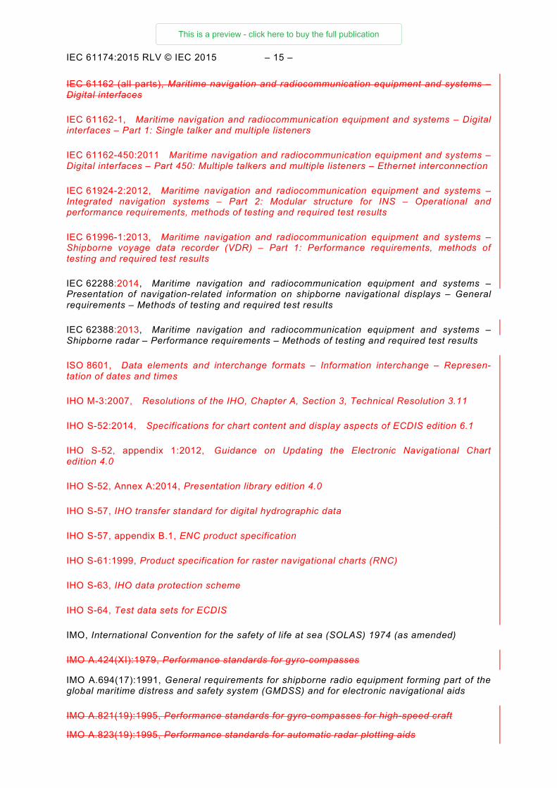
IEC 61162 (all parts), Maritime navigation and radiocommunication equipment and systems – Digital interfaces
IEC 61162-1, Maritime navigation and radiocommunication equipment and systems – Digital interfaces – Part 1: Single talker and multiple listeners
IEC 61162-450:2011 Maritime navigation and radiocommunication equipment and systems – Digital interfaces – Part 450: Multiple talkers and multiple listeners – Ethernet interconnection
IEC 61924-2:2012, Maritime navigation and radiocommunication equipment and systems – Integrated navigation systems – Part 2: Modular structure for INS – Operational and performance requirements, methods of testing and required test results
IEC 61996-1:2013, Maritime navigation and radiocommunication equipment and systems – Shipborne voyage data recorder (VDR) – Part 1: Performance requirements, methods of testing and required test results
IEC 62288:2014, Maritime navigation and radiocommunication equipment and systems – Presentation of navigation-related information on shipborne navigational displays – General requirements – Methods of testing and required test results
IEC 62388:2013, Maritime navigation and radiocommunication equipment and systems – Shipborne radar – Performance requirements – Methods of testing and required test results
ISO 8601, Data elements and interchange formats – Information interchange – Represen-tation of dates and times
IHO M-3:2007, Resolutions of the IHO, Chapter A, Section 3, Technical Resolution 3.11
IHO S-52:2014, Specifications for chart content and display aspects of ECDIS edition 6.1
IHO S-52, appendix 1:2012, Guidance on Updating the Electronic Navigational Chart edition 4.0
IHO S-52, Annex A:2014, Presentation library edition 4.0
IHO S-57, IHO transfer standard for digital hydrographic data
IHO S-57, appendix B.1, ENC product specification
IHO S-61:1999, Product specification for raster navigational charts (RNC)
IHO S-63, IHO data protection scheme
IHO S-64, Test data sets for ECDIS
IMO, International Convention for the safety of life at sea (SOLAS) 1974 (as amended)
IMO A.424(XI):1979, Performance standards for gyro-compasses
IMO A.694(17):1991, General requirements for shipborne radio equipment forming part of the global maritime distress and safety system (GMDSS) and for electronic navigational aids
IMO A.821(19):1995, Performance standards for gyro-compasses for high-speed craft
IMO A.823(19):1995, Performance standards for automatic radar plotting aids
This is a preview - click here to buy the full publication
– 16 – IEC 61174:2015 RLV © IEC 2015
IMO A.824(19):1995, Performance standards for devices to indicate speed and distance
IMO A.830(19):1995, Code on Alarms and Indicators
IMO MSC.191(79):2004, Performance standards for the presentation of navigation-related information on shipborne navigational displays
IMO MSC.192(79), Revised performance standards for radar equipment
IMO MSC.232(82):2006, Revised Performance standards for electronic chart display and information systems (ECDIS)
IMO MSC.252(83), Performance standards for integrated navigation systems (INS)
IMO MSC/Circ.982:2000, Guidelines on ergonomic criteria for bridge equipment and layout
IMO SN/Circ.243 (2004), Guidelines for the Presentation of Navigation-related Symbols, Terms and Abbreviations
IMO SN.1/Circ.266:2007, Maintenance of electronic chart display and information system (ECDIS) software
IHO M-3:2007, Resolutions of the IHO, Chapter A, Section 3, Technical Resolution 3.11
IHO S-32, appendix 1, Hydrographic dictionary – Glossary of ECDIS related terms
IHO S-52:1996, Specifications for chart content and display aspects of ECDIS
IHO S-52, appendix 1:1996, Guidance on updating the electronic navigational chart
IHO S-52, appendix 2:2004 Colour and symbol specifications for ECDIS
IHO S-57, appendix B.1: 2000, ENC product specification
IHO S-61:1999, Product specification for raster navigational charts (RNC)
IHO S-63:2008, IHO data protection scheme
IHO S-64, Test data sets for ECDIS
3 Terms, definitions and abbreviations
For the purposes of this document, the terms, definitions and abbreviations given in IEC 62288, as well as the following apply.
3.1 Terms and definitions
3.1.1 activated AIS target (MSC.191/A) target activated for the display of additional graphically presented information
EXAMPLE Heading line, velocity vector, etc.
[SOURCE: IEC 62288:2014, 3.1]
3.1.2 appropriate portfolio of up to date paper charts APC a suite of paper charts of a scale to show sufficient detail of topography, depths, navigational hazards, aids to navigation, charted routes, and routeing measures to provide the mariner with information on the overall navigational environment. The APC should provide adequate look-ahead capability. Coastal States will provide details of the charts which meet the
This is a preview - click here to buy the full publication
IEC 61174 Edition 4.0 2015-08
INTERNATIONAL STANDARD
Maritime navigation and radiocommunication equipment and systems – Electronic chart display and information system (ECDIS) – Operational and performance requirements, methods of testing and required test results
IEC
611
74:2
015-
08(e
n)
®
colourinside
This is a preview - click here to buy the full publication
– 2 – IEC 61174:2015 © IEC 2015
CONTENTS
FOREWORD ......................................................................................................................... 12 1 Scope ............................................................................................................................ 14 2 Normative references .................................................................................................... 14 3 Terms, definitions and abbreviations ............................................................................. 16
3.1 Terms and definitions ............................................................................................ 16 3.2 Abbreviations ........................................................................................................ 21
4 Minimum operational and performance requirements ..................................................... 22 4.1 General ................................................................................................................. 22 4.2 ECDIS definitions .................................................................................................. 23 4.3 Display of SENC information ................................................................................. 23
4.3.1 SENC .......................................................................................................... 23 4.3.2 Indication about use of non-HO source ........................................................ 23 4.3.3 Categories of display ................................................................................... 23 4.3.4 Safety contour ............................................................................................. 24 4.3.5 Safety depth ................................................................................................ 25 4.3.6 Information content ...................................................................................... 25 4.3.7 Verification and updates .............................................................................. 25 4.3.8 Information about chart objects .................................................................... 25 4.3.9 Display scale ............................................................................................... 25
4.4 Provision and updating of chart information .......................................................... 25 4.4.1 Contents of the SENC .................................................................................. 25 4.4.2 Updates ....................................................................................................... 26
4.5 Scale .................................................................................................................... 26 4.6 Display of other navigational information ............................................................... 26
4.6.1 General for all overlays ................................................................................ 26 4.6.2 Radar information ........................................................................................ 27 4.6.3 AIS information ............................................................................................ 30 4.6.4 AIS target data............................................................................................. 32 4.6.5 AIS voyage-related data .............................................................................. 33 4.6.6 AIS CPA/TCPA alarms ................................................................................. 33 4.6.7 AIS lost target warning ................................................................................. 34 4.6.8 Anchor watch ............................................................................................... 34
4.7 Display mode and generation of the neighbouring area ......................................... 35 4.8 Colours and symbols............................................................................................. 35 4.9 Display requirements ............................................................................................ 36
4.9.1 Route planning and monitoring .................................................................... 36 4.9.2 Chart presentation size ................................................................................ 36 4.9.3 Colour and resolution ................................................................................... 36 4.9.4 Presentation ................................................................................................ 36 4.9.5 Removal of information categories ............................................................... 36
4.10 Route planning, monitoring and voyage recording ................................................. 36 4.10.1 General........................................................................................................ 36 4.10.2 Route planning ............................................................................................ 37 4.10.3 Route monitoring ......................................................................................... 38 4.10.4 Position integration ...................................................................................... 40 4.10.5 Object information........................................................................................ 41
This is a preview - click here to buy the full publication
IEC 61174:2015 © IEC 2015 – 3 –
4.10.6 LOP position fix ........................................................................................... 41 4.10.7 Voyage recording ......................................................................................... 41
4.11 Calculations and accuracy .................................................................................... 42 4.12 Connections with other equipment (interfaces) ...................................................... 42
4.12.1 Connection with navigation equipment ......................................................... 42 4.12.2 Connection with BAM ................................................................................... 42 4.12.3 Connection with VDR ................................................................................... 43 4.12.4 Connection with BNWAS .............................................................................. 44 4.12.5 Connection for SENC information ................................................................ 44 4.12.6 Connection with NAVTEX or SafetyNET for MSI .......................................... 44 4.12.7 Connection for transfer of route information ................................................. 45 4.12.8 Connection with INS .................................................................................... 46
4.13 Performance tests, malfunction alerts and indications ........................................... 46 4.14 Back-up arrangements .......................................................................................... 46 4.15 Power supply ........................................................................................................ 46 4.16 Software maintenance .......................................................................................... 46 4.17 Quality management requirements ........................................................................ 47 4.18 Default control setting and saved user control settings .......................................... 47
5 Requirements contained in IHO publications .................................................................. 49 5.1 Priority of chart display ......................................................................................... 49 5.2 Display of chart information .................................................................................. 50
5.2.1 Scale and navigation purpose ...................................................................... 50 5.2.2 Units and legend .......................................................................................... 50 5.2.3 Terminology ................................................................................................. 51
5.3 Display functions .................................................................................................. 51 5.3.1 Cursor pick .................................................................................................. 51 5.3.2 Navigational information .............................................................................. 51 5.3.3 Date-dependant ENC objects ....................................................................... 52
5.4 Supplementary display functions ........................................................................... 52 5.4.1 Additional mariner’s information ................................................................... 52 5.4.2 Additional non-HO information ..................................................................... 52 5.4.3 Tidal adjustment .......................................................................................... 53
5.5 Use of the presentation library .............................................................................. 53 5.5.1 Presentation library ...................................................................................... 53 5.5.2 Test diagrams .............................................................................................. 53
5.6 Display characteristics .......................................................................................... 53 5.7 Performance requirements .................................................................................... 54
5.7.1 Redraw ........................................................................................................ 54 5.7.2 Resolution ................................................................................................... 54 5.7.3 Symbols ....................................................................................................... 54 5.7.4 Number of colours ....................................................................................... 55 5.7.5 Brightness and contrast ............................................................................... 55
5.8 Ergonomic requirements ....................................................................................... 55 5.8.1 Mode and orientation ................................................................................... 55 5.8.2 Windows ...................................................................................................... 55
5.9 Update of chart information ................................................................................... 56 5.9.1 General........................................................................................................ 56 5.9.2 Manual update ............................................................................................. 57 5.9.3 Semi-automatic update ................................................................................ 58
This is a preview - click here to buy the full publication
– 4 – IEC 61174:2015 © IEC 2015
5.9.4 Reception of updates ................................................................................... 58 5.9.5 Sequence check .......................................................................................... 58 5.9.6 Consistency check ....................................................................................... 59 5.9.7 Geographic applicability ............................................................................... 59 5.9.8 Summary report ........................................................................................... 59 5.9.9 Review of ENC updates ............................................................................... 59 5.9.10 Modification of updates ................................................................................ 59
5.10 Operational area ................................................................................................... 59 5.11 External removable media ..................................................................................... 60
6 Methods of testing and required test results .................................................................. 60 6.1 EUT installation, technical documentation, and test requirements ......................... 60 6.2 Interfaces .............................................................................................................. 60
6.2.1 General........................................................................................................ 60 6.2.2 BAM interface .............................................................................................. 61 6.2.3 VDR interface .............................................................................................. 62 6.2.4 BNWAS interface ......................................................................................... 63
6.3 General requirements and presentation requirements ........................................... 63 6.3.1 General requirements .................................................................................. 63 6.3.2 Presentation requirements ........................................................................... 63
6.4 Preparation ........................................................................................................... 63 6.4.1 Power-up ..................................................................................................... 63 6.4.2 Initial ship parameters.................................................................................. 64 6.4.3 Required test items ...................................................................................... 64
6.5 Requirements related to ENC chart ....................................................................... 64 6.5.1 General........................................................................................................ 64 6.5.2 Presentation library ...................................................................................... 65 6.5.3 ENC ............................................................................................................. 65 6.5.4 Encrypted ENC ............................................................................................ 65
6.6 Accuracy ............................................................................................................... 65 6.7 Visual requirements .............................................................................................. 65
6.7.1 Symbols ....................................................................................................... 65 6.7.2 Terminology, units and legend ..................................................................... 65 6.7.3 Colour table ................................................................................................. 65 6.7.4 Resolution ................................................................................................... 66 6.7.5 Display characteristics ................................................................................. 66
6.8 Functional requirements ........................................................................................ 66 6.8.1 Methods of testing ....................................................................................... 66 6.8.2 Standard display .......................................................................................... 66 6.8.3 Display base ................................................................................................ 66 6.8.4 All other information ..................................................................................... 67 6.8.5 Viewing group layers and text group layers .................................................. 67 6.8.6 Display priorities .......................................................................................... 67 6.8.7 Additional display functions .......................................................................... 67 6.8.8 Scale and navigation purpose ...................................................................... 67 6.8.9 Mode and orientation ................................................................................... 68 6.8.10 Safety contour ............................................................................................. 68 6.8.11 Safety depth ................................................................................................ 68 6.8.12 Cursor pick .................................................................................................. 68 6.8.13 Navigation related functions ......................................................................... 68
This is a preview - click here to buy the full publication
IEC 61174:2015 © IEC 2015 – 5 –
6.8.14 Position integration ...................................................................................... 69 6.8.15 Radar and other navigational information ..................................................... 69 6.8.16 Loading of corrupted data ............................................................................ 72 6.8.17 Automatic updates ....................................................................................... 72 6.8.18 Manual updates ........................................................................................... 73 6.8.19 Self-tests of major functions ......................................................................... 73 6.8.20 Operational area .......................................................................................... 73 6.8.21 External removable media............................................................................ 74
6.9 Operational requirements ...................................................................................... 74 6.9.1 Ergonomic principles.................................................................................... 74 6.9.2 Route planning ............................................................................................ 74 6.9.3 Route monitoring ......................................................................................... 76 6.9.4 Twelve hour log ........................................................................................... 78 6.9.5 Voyage record ............................................................................................. 78 6.9.6 Power supply ............................................................................................... 78 6.9.7 LOP position fix ........................................................................................... 78
6.10 Software maintenance .......................................................................................... 79 6.11 Quality management ............................................................................................. 79 6.12 Default control setting and saved operator control settings ................................... 80 6.13 AIS information and AIS target data ...................................................................... 80
6.13.1 General........................................................................................................ 80 6.13.2 AIS targets and data report capacity ............................................................ 80 6.13.3 AIS target filtering ........................................................................................ 80 6.13.4 Activation and deactivation of AIS targets .................................................... 81 6.13.5 AIS functionality and presentation ................................................................ 81 6.13.6 AIS target data............................................................................................. 82 6.13.7 AIS CPA/TCPA alarm................................................................................... 83 6.13.8 AIS lost target warning ................................................................................. 83
6.14 AIS Voyage-related data ....................................................................................... 84 6.15 Anchor watch ........................................................................................................ 84 6.16 NAVTEX and SafetyNET for MSI ........................................................................... 85 6.17 Interface for transfer of route information .............................................................. 85 6.18 Interface with INS ................................................................................................. 86
Annex A (normative) SENC information to be displayed during route planning and route monitoring ............................................................................................................ 87
Annex B (normative) Navigational elements and parameters ................................................ 88 Annex C (normative) Areas for which special conditions exist .............................................. 89 Annex D (normative) Alerts and indications .......................................................................... 90 Annex E (normative) Mandatory terminology and abbreviations ........................................... 92 Annex F (normative) Back-up arrangements ........................................................................ 98
F.1 Overview............................................................................................................... 98 F.2 Purpose ................................................................................................................ 98 F.3 Functional requirements ........................................................................................ 98
F.3.1 Required functions and their availability ....................................................... 98 F.3.2 Reliability and accuracy ............................................................................. 102 F.3.3 Malfunctions, warnings, alerts and indications ........................................... 102
F.4 Operational requirements .................................................................................... 102 F.4.1 Ergonomics ................................................................................................ 102
This is a preview - click here to buy the full publication
– 6 – IEC 61174:2015 © IEC 2015
F.4.2 Presentation of information ........................................................................ 102 F.5 Power supply ...................................................................................................... 103 F.6 Other requirement ............................................................................................... 103
F.6.1 Connection with other systems .................................................................. 103 F.6.2 Route transfer interface ............................................................................. 104 F.6.3 Radar as back-up system........................................................................... 104 F.6.4 Operational area ........................................................................................ 104 F.6.5 Software maintenance ............................................................................... 104 F.6.6 Quality management .................................................................................. 104 F.6.7 Default Control Settings and Saved User Control Settings ......................... 104 F.6.8 External removable media.......................................................................... 104
F.7 Methods of testing and required test results ........................................................ 105 F.7.1 EUT installation and technical documentation ............................................ 105 F.7.2 Interfaces .................................................................................................. 105 F.7.3 General requirements and presentation requirements ................................ 105 F.7.4 Preparation ................................................................................................ 105 F.7.5 Initial data tests – Chart ............................................................................. 106 F.7.6 Accuracy .................................................................................................... 106 F.7.7 Visual requirements ................................................................................... 106 F.7.8 Functional requirements ............................................................................ 106 F.7.9 Operational requirements ........................................................................... 108
Annex G (normative) ECDIS in the RCDS mode of operation ............................................. 111 G.1 Overview............................................................................................................. 111 G.2 RCDS definitions ................................................................................................ 111 G.3 Display of SRNC information ............................................................................... 112
G.3.1 SRNC ........................................................................................................ 112 G.3.2 Categories of display ................................................................................. 112 G.3.3 Power failure ............................................................................................. 112 G.3.4 Information content .................................................................................... 112 G.3.5 Verification and updates ............................................................................ 112 G.3.6 Indication ................................................................................................... 113
G.4 Provision and updating of chart information ........................................................ 113 G.4.1 Contents of the RNC .................................................................................. 113 G.4.2 Updates ..................................................................................................... 113
G.5 Scale .................................................................................................................. 114 G.6 Display of other navigational information ............................................................. 114
G.6.1 General for all overlays .............................................................................. 114 G.6.2 Radar information ...................................................................................... 114 G.6.3 AS information ........................................................................................... 115 G.6.4 AIS Target Data ......................................................................................... 115 G.6.5 AIS Voyage Related Data .......................................................................... 115 G.6.6 AIS CPA/TCPA alarms ............................................................................... 115 G.6.7 AIS lost target warning ............................................................................... 115 G.6.8 Anchor watch ............................................................................................. 115
G.7 Display mode and generation of the neighbouring area ....................................... 115 G.8 Colours and symbols........................................................................................... 116 G.9 Display requirements .......................................................................................... 116
G.9.1 Route planning and monitoring .................................................................. 116 G.9.2 Display characteristics ............................................................................... 116
This is a preview - click here to buy the full publication
IEC 61174:2015 © IEC 2015 – 7 –
G.9.3 Chart notes ................................................................................................ 117 G.10 Route planning, monitoring and voyage recording ............................................... 117
G.10.1 General...................................................................................................... 117 G.10.2 Route planning .......................................................................................... 117 G.10.3 Route monitoring ....................................................................................... 117 G.10.4 Position integration .................................................................................... 118 G.10.5 Object information...................................................................................... 119 G.10.6 LOP position fix ......................................................................................... 119 G.10.7 Voyage recording ....................................................................................... 119
G.11 Calculations and accuracy .................................................................................. 120 G.12 Connections with other equipment (interfaces) .................................................... 120 G.13 Performance tests, malfunction alerts and indications ......................................... 121 G.14 Back-up arrangements for RCDS mode of operation ........................................... 121 G.15 Power supply for RCDS mode of operation ......................................................... 121 G.16 Requirements contained in IHO publications ....................................................... 122
G.16.1 Structure of RNC data ................................................................................ 122 G.16.2 RNC data resolution and accuracy ............................................................. 122 G.16.3 RNC meta-data .......................................................................................... 122 G.16.4 RNC colours .............................................................................................. 122 G.16.5 RNC notes, diagrams, etc .......................................................................... 123 G.16.6 Operational area ........................................................................................ 123 G.16.7 External removable media.......................................................................... 123
G.17 Methods of testing and required test results ........................................................ 123 G.17.1 Preparation – Required test items .............................................................. 123 G.17.2 Initial data tests ......................................................................................... 124 G.17.3 Accuracy .................................................................................................... 124 G.17.4 Visual requirements ................................................................................... 125 G.17.5 Functional requirements ............................................................................ 126 G.17.6 Operational requirement ............................................................................ 131
G.18 RNC test data set ............................................................................................... 134 Annex H (normative) Alerts and indications in the RCDS mode of operation ...................... 135 Annex I (normative) Scenario definitions and plots ............................................................. 136
I.1 Overview............................................................................................................. 136 I.2 Scenario 1: ......................................................................................................... 137 I.3 Scenario 2: ......................................................................................................... 138 I.4 Scenario 3: ......................................................................................................... 140 I.5 Scenario 4: ......................................................................................................... 141
Annex J (informative) Guidance on geodetic calculations ................................................... 144 J.1 Overview............................................................................................................. 144 J.2 Distance deviations between Great Circle (orthodrome) and Rhumb Line
(loxodrome) ........................................................................................................ 144 J.3 Bearing deviations at start point between Great Circle (orthodrome) and
Rhumb Line (loxodrome) ..................................................................................... 145 Annex K (informative) Guidance for testing ........................................................................ 147
K.1 Methods of test derived from ISO 9241-12 .......................................................... 147 K.2 Observation ........................................................................................................ 147 K.3 Inspection of documented evidence .................................................................... 147 K.4 Measurement ...................................................................................................... 147 K.5 Analytical evaluation ........................................................................................... 148
This is a preview - click here to buy the full publication
– 8 – IEC 61174:2015 © IEC 2015
Annex L (informative) Examples of ENC Update Status Report .......................................... 149 L.1 Overview............................................................................................................. 149 L.2 ENC Update Status Report − Summary ............................................................... 149 L.3 ENC Update Status Report − Full ........................................................................ 150 L.4 ENC Management Report – Route Filtered ......................................................... 152
Annex M (normative) Elements of an electronic chart database ......................................... 153 M.1 General ............................................................................................................... 153 M.2 ECDIS implementation ........................................................................................ 153 M.3 Display base category ......................................................................................... 154
M.3.1 Coastline layer ........................................................................................... 154 M.3.2 Safety contour layer ................................................................................... 155 M.3.3 Isolated underwater dangers layer ............................................................. 155 M.3.4 Isolated above-water dangers layer ........................................................... 155
M.4 Standard display category ................................................................................... 156 M.4.1 Display base layer ..................................................................................... 156 M.4.2 Additional aids to navigation and fixed structures layer .............................. 156 M.4.3 Fairways layer ........................................................................................... 156 M.4.4 Conspicuous features layer ........................................................................ 156 M.4.5 Prohibited and restricted areas layer .......................................................... 157 M.4.6 Ferry routes layer ...................................................................................... 157 M.4.7 Archipelagic sea lanes layer ...................................................................... 157 M.4.8 Buoys and beacons layer ........................................................................... 157 M.4.9 Traffic routeing layer .................................................................................. 157
M.5 All other information category ............................................................................. 158 M.5.1 Information about the chart display layer .................................................... 158 M.5.2 Natural and man-made features, Port features layer .................................. 158 M.5.3 Depth, currents, etc. layer .......................................................................... 159 M.5.4 Seabed, obstructions, pipelines layer ......................................................... 160 M.5.5 Traffic routes layer ..................................................................................... 160 M.5.6 Special areas layer .................................................................................... 160 M.5.7 Service and small craft facilities layer ........................................................ 161
M.6 Text grouping ...................................................................................................... 161 M.6.1 Important Text group layer ......................................................................... 161 M.6.2 Other Text group layer ............................................................................... 161
Annex N (informative) Use cases for safety contour and safety depth ................................ 163 Annex O (informative) Guidelines on use of electronic chart systems in polar waters ......... 165
O.1 Projection and coordinate system ....................................................................... 165 O.2 Consistency ........................................................................................................ 166
Annex P (normative) Scenarios for polar areas above 85° North ........................................ 167 Annex Q (normative) IEC 61162 interfaces ........................................................................ 173
Q.1 General ............................................................................................................... 173 Q.2 VDR interface ..................................................................................................... 176 Q.3 AIS interface and interrogation ............................................................................ 176 Q.4 Route transfer interface ...................................................................................... 177 Q.5 BAM interface ..................................................................................................... 177
Annex R (informative) Conversion between IEC 61162-1 sentences and IEC 61162-3 parameter group numbers ............................................................................................ 181
Annex S (normative) Route plan exchange format – RTZ ................................................... 183
This is a preview - click here to buy the full publication
IEC 61174:2015 © IEC 2015 – 9 –
S.1 General ............................................................................................................... 183 S.2 RTP Data container ............................................................................................ 184 S.3 High-level description of the RTZ format ............................................................. 185 S.4 Adaptation to third-party extensions .................................................................... 185
S.4.1 Generic idea .............................................................................................. 185 S.4.2 Unique identification of a waypoint ............................................................. 185 S.4.3 Creation of new waypoints ......................................................................... 186 S.4.4 Change of geographic data for a waypoint ................................................. 186 S.4.5 Waypoint removal ...................................................................................... 186
S.5 Detailed RTZ format description .......................................................................... 186 S.5.1 File components ........................................................................................ 186 S.5.2 Route node description .............................................................................. 186 S.5.3 RouteInfo node description ........................................................................ 187 S.5.4 Waypoints node description ....................................................................... 188 S.5.5 DefaultWaypoint node description .............................................................. 188 S.5.6 Waypoint node description ......................................................................... 189 S.5.7 Storing date and time for legs .................................................................... 190 S.5.8 Schedules node description ....................................................................... 190 S.5.9 Schedule node description ......................................................................... 190 S.5.10 Extensions node description ...................................................................... 192 S.5.11 Extension node description ........................................................................ 193
S.6 XML schema to be met by RTZ route files ........................................................... 193 S.7 Basic RTZ route example .................................................................................... 205 S.8 Example of the RTZ route with embedded extensions ......................................... 206 S.9 UML model of the Route exchange format........................................................... 207
Annex T (normative) Interface for reporting route transfer .................................................. 209 T.1 Route encapsulation format for transmitting RTZ over IEC 61162-450 ................ 209 T.2 RRT – Report route transfer ................................................................................ 210
Annex U (normative) Sentences used by SafetyNET .......................................................... 211 U.1 General ............................................................................................................... 211 U.2 SM1 – SafetyNET Message, All Ships/NavArea .................................................. 211 U.3 SM2 – SafetyNET Message, Coastal Warning Area ............................................ 213 U.4 SM3 – SafetyNET Message, Circular Area Address ............................................ 215 U.5 SM4 – SafetyNET Message, Rectangular Area Address ...................................... 217 U.6 SMB – IMO SafetyNET Message Body ................................................................ 220 U.7 An example of use .............................................................................................. 221
Annex V (normative) Extension of TTD sentence, Protocol version 1 ................................. 222 V.1 General ............................................................................................................... 222 V.2 TTD – Tracked target data, Protocol version 1 .................................................... 222
Annex W (normative) Symbols ........................................................................................... 223 Bibliography ........................................................................................................................ 224 Figure F.1 – Backup system logical interfaces .................................................................... 103 Figure I.1 – Definition of elements of route ......................................................................... 136 Figure I.2 – Route for scenario 1 ......................................................................................... 138 Figure I.3 – Route for scenario 2 ......................................................................................... 139 Figure I.4 – Route for scenario 3 ......................................................................................... 140
This is a preview - click here to buy the full publication
– 10 – IEC 61174:2015 © IEC 2015
Figure I.5 – Route for scenario 4 ......................................................................................... 143 Figure J.1 – Distance deviations between Great Circle and Rhumb Line ............................. 144 Figure J.2 – Bearing deviations at start point between Great Circle and Rhumb Line .......... 146 Figure N.1 – Original situation ............................................................................................ 163 Figure N.2 – New situation .................................................................................................. 164 Figure P.1 – Examples of use of the tables ......................................................................... 167 Figure Q.1 – ECDIS logical interfaces ................................................................................. 173 Figure Q.2 – Alert reporting by ECDIS without escalation of a warning ............................... 177 Figure Q.3 – Alert reporting by ECDIS with escalation of a warning as alarm ...................... 178 Figure Q.4 – Alert reporting by ECDIS in case of remote acknowledge ............................... 178 Figure Q.5 – Alert reporting by ECDIS in case of remote silence ......................................... 179 Figure Q.6 – Alert reporting by ECDIS in case of remote silence ......................................... 180 Figure Q.7 – Alert reporting by ECDIS in case of remote silence ......................................... 180 Figure S.1 – Description of route plan – Distance between WP 2 and WP 3 ........................ 184 Figure S.2 – Description of route plan – Leg parameters belonging to WP 3 ....................... 184 Figure S.3 – UML diagram .................................................................................................. 208 Figure T.1 – Examples of timing for route transfer ............................................................... 209 Table 1 – Tracked target display capacity ............................................................................. 28 Table 2 – AIS display capacity .............................................................................................. 30 Table 3 – Control settings configured in response to ‘Default’ selection ................................ 47 Table D.1 – Alerts and indications resulting from IMO requirements ...................................... 90 Table D.2 – Alerts and indications defined in this standard ................................................... 91 Table E.1 – Chart display terminology ................................................................................... 92 Table E.2 – Main function terminology .................................................................................. 94 Table E.3 – Database terminology ........................................................................................ 95 Table E.4 – Route, route monitoring or route plan related terminology .................................. 96 Table H.1 – Alerts and indications in the RCDS mode of operation ..................................... 135 Table J.1 – Rhumb Line distances ...................................................................................... 145 Table J.2 – Deviations from Great Circle distances ............................................................. 146 Table M.1 – Minimum ECDIS mariner viewing group layer selectors ................................... 153 Table M.2 – Minimum ECDIS mariner text group layer selectors ......................................... 154 Table P.1 – Spatial control points from 85°N, 0°E as origin ................................................. 168 Table P.2 – Spatial control points from 87°N, 0°E as origin ................................................. 169 Table P.3 – Spatial control points from 89°N, 0°E as origin ................................................. 170 Table P.4 – Spatial control points from 90°N, 0°E as origin, 180°E as origin of relative bearings.............................................................................................................................. 171 Table Q.1 – Mandatory sentences received by ECDIS ........................................................ 174 Table Q.2 – Optional sentences received by ECDIS ............................................................ 175 Table Q.3 – Mandatory sentences transmitted by the ECDIS .............................................. 175 Table Q.4 – Optional sentences transmitted by the ECDIS .................................................. 176 Table Q.5 – Mandatory information transmitted to the VDR ................................................. 176 Table Q.6 – Information between the ECDIS and an ECDIS backup system ........................ 177
This is a preview - click here to buy the full publication

IEC 61174:2015 © IEC 2015 – 11 –
Table R.1 – Conversion from IEC 61162-1 to IEC 61162-3 .................................................. 181 Table R.2 – Conversion from IEC 61162-3 to IEC 61162-1 .................................................. 182 Table W.1 – Anchor watch symbol ...................................................................................... 223
This is a preview - click here to buy the full publication
– 12 – IEC 61174:2015 © IEC 2015
INTERNATIONAL ELECTROTECHNICAL COMMISSION
____________
MARITIME NAVIGATION AND RADIOCOMMUNICATION
EQUIPMENT AND SYSTEMS –
Electronic chart display and information system (ECDIS) – Operational and performance requirements, methods of testing and required test results
FOREWORD
1) The International Electrotechnical Commission (IEC) is a worldwide organization for standardization comprising all national electrotechnical committees (IEC National Committees). The object of IEC is to promote international co-operation on all questions concerning standardization in the electrical and electronic fields. To this end and in addition to other activities, IEC publishes International Standards, Technical Specifications, Technical Reports, Publicly Available Specifications (PAS) and Guides (hereafter referred to as “IEC Publication(s)”). Their preparation is entrusted to technical committees; any IEC National Committee interested in the subject dealt with may participate in this preparatory work. International, governmental and non-governmental organizations liaising with the IEC also participate in this preparation. IEC collaborates closely with the International Organization for Standardization (ISO) in accordance with conditions determined by agreement between the two organizations.
2) The formal decisions or agreements of IEC on technical matters express, as nearly as possible, an international consensus of opinion on the relevant subjects since each technical committee has representation from all interested IEC National Committees.
3) IEC Publications have the form of recommendations for international use and are accepted by IEC National Committees in that sense. While all reasonable efforts are made to ensure that the technical content of IEC Publications is accurate, IEC cannot be held responsible for the way in which they are used or for any misinterpretation by any end user.
4) In order to promote international uniformity, IEC National Committees undertake to apply IEC Publications transparently to the maximum extent possible in their national and regional publications. Any divergence between any IEC Publication and the corresponding national or regional publication shall be clearly indicated in the latter.
5) IEC itself does not provide any attestation of conformity. Independent certification bodies provide conformity assessment services and, in some areas, access to IEC marks of conformity. IEC is not responsible for any services carried out by independent certification bodies.
6) All users should ensure that they have the latest edition of this publication.
7) No liability shall attach to IEC or its directors, employees, servants or agents including individual experts and members of its technical committees and IEC National Committees for any personal injury, property damage or other damage of any nature whatsoever, whether direct or indirect, or for costs (including legal fees) and expenses arising out of the publication, use of, or reliance upon, this IEC Publication or any other IEC Publications.
8) Attention is drawn to the Normative references cited in this publication. Use of the referenced publications is indispensable for the correct application of this publication.
9) Attention is drawn to the possibility that some of the elements of this IEC Publication may be the subject of patent rights. IEC shall not be held responsible for identifying any or all such patent rights.
International Standard IEC 61174 has been prepared by IEC technical committee 80: Maritime navigation and radiocommunication equipment and systems.
This fourth edition of IEC 61174 cancels and replaces the third edition published in 2008, of which it constitutes a technical revision.
This edition includes the following significant technical changes with respect to the previous edition:
• updated references are provided to IHO publications and test methods are updated to IHO test data sets;
• requirements have been added for display of radar and AIS information;
This is a preview - click here to buy the full publication
IEC 61174:2015 © IEC 2015 – 13 –
• new interface requirements have been added for BNWAS, VDR, BAM, MSI, INS and route transfer;
• a requirement for an anchor watch has been added;
• additional test methods are specified for operation of ECDIS beyond the normal range between 85 degrees South latitude and 85 degrees North latitude.
The text of this standard is based on the following documents:
FDIS Report on voting
80/761/FDIS 80/767/RVD
Full information on the voting for the approval of this standard can be found in the report on voting indicated in the above table.
This publication has been drafted in accordance with the ISO/IEC Directives, Part 2.
The committee has decided that the contents of this publication will remain unchanged until the maintenance result date indicated on the IEC web site under "http://webstore.iec.ch" in the data related to the specific publication. At this date, the publication will be
• reconfirmed, • withdrawn, • replaced by a revised edition, or • amended.
A bilingual version of this publication may be issued at a later date.
IMPORTANT – The 'colour inside' logo on the cover page of this publication indicates that it contains colours which are considered to be useful for the correct understanding of its contents. Users should therefore print this document using a colour printer.
This is a preview - click here to buy the full publication
– 14 – IEC 61174:2015 © IEC 2015
MARITIME NAVIGATION AND RADIOCOMMUNICATION EQUIPMENT AND SYSTEMS –
Electronic chart display and information system (ECDIS) –
Operational and performance requirements, methods of testing and required test results
1 Scope
This International Standard specifies the performance requirements, methods of testing and required test results of equipment conforming to performance standards not inferior to those adopted by the IMO in resolution MSC.232(82).
This standard is based upon the performance standards of IMO resolution MSC.232(82), and is also associated with IMO resolution A.694(17) and IEC 60945. Reference is made, where appropriate, to IMO resolution MSC.232(82), and all subclauses whose wording is identical to that in the resolution are printed in italics.
In association with the above IMO resolution MSC.232(82), are the International Hydrographic Organization (IHO) publications1. IHO S-32, IHO S-52, IHO S-57, IHO S-61, IHO S-63 and IHO S-64. This standard has included extracts from the above publications where they are applicable to this equipment. Where reference is made, all subclauses whose wording is identical to that in the publications, are printed in italics.
(232/A2.1) These performance standards should apply to all ECDIS equipment carried on all ships as follows:
– dedicated standalone workstation.
– a multifunction workstation as part of an INS.
(232/A2.2) These performance standards apply to ECDIS mode of operation, ECDIS in RCDS mode of operation as specified in Annex G and ECDIS backup arrangements as specified in Annex F.
(232/A2.3) Requirements for structure and format of the chart data, encryption of chart data as well as the presentation of chart data are within the scope of relevant IHO standards, including those listed in the normative references.
The requirements of this standard are not intended to prevent the use of new techniques in equipment and systems, provided the facilities offered are not inferior to those stated.
2 Normative references
The following documents, in whole or in part, are normatively referenced in this document and are indispensable for its application. For dated references, only the edition cited applies. For undated references, the latest edition of the referenced document (including any amendments) applies.
IEC 60945, Maritime navigation and radiocommunication equipment and systems – General requirements – Methods of testing and required test results
___________
1 IHO publications are available from http://www.iho.int, together with any supplementary information.
This is a preview - click here to buy the full publication
IEC 61174:2015 © IEC 2015 – 15 –
IEC 61162-1, Maritime navigation and radiocommunication equipment and systems – Digital interfaces – Part 1: Single talker and multiple listeners
IEC 61162-450:2011 Maritime navigation and radiocommunication equipment and systems – Digital interfaces – Part 450: Multiple talkers and multiple listeners – Ethernet interconnection
IEC 61924-2:2012, Maritime navigation and radiocommunication equipment and systems – Integrated navigation systems – Part 2: Modular structure for INS – Operational and performance requirements, methods of testing and required test results
IEC 61996-1:2013, Maritime navigation and radiocommunication equipment and systems – Shipborne voyage data recorder (VDR) – Part 1: Performance requirements, methods of testing and required test results
IEC 62288:2014, Maritime navigation and radiocommunication equipment and systems – Presentation of navigation-related information on shipborne navigational displays – General requirements – Methods of testing and required test results
IEC 62388:2013, Maritime navigation and radiocommunication equipment and systems – Shipborne radar – Performance requirements – Methods of testing and required test results
ISO 8601, Data elements and interchange formats – Information interchange – Represen-tation of dates and times
IHO M-3:2007, Resolutions of the IHO, Chapter A, Section 3, Technical Resolution 3.11
IHO S-52:2014, Specifications for chart content and display aspects of ECDIS edition 6.1
IHO S-52, appendix 1:2012, Guidance on Updating the Electronic Navigational Chart edition 4.0
IHO S-52, Annex A:2014, Presentation library edition 4.0
IHO S-57, IHO transfer standard for digital hydrographic data
IHO S-57, appendix B.1, ENC product specification
IHO S-61:1999, Product specification for raster navigational charts (RNC)
IHO S-63, IHO data protection scheme
IHO S-64, Test data sets for ECDIS
IMO, International Convention for the safety of life at sea (SOLAS) 1974 (as amended)
IMO A.694(17):1991, General requirements for shipborne radio equipment forming part of the global maritime distress and safety system (GMDSS) and for electronic navigational aids
IMO MSC.191(79):2004, Performance standards for the presentation of navigation-related information on shipborne navigational displays
IMO MSC.232(82):2006, Revised Performance standards for electronic chart display and information systems (ECDIS)
IMO MSC.252(83), Performance standards for integrated navigation systems (INS)
This is a preview - click here to buy the full publication

– 16 – IEC 61174:2015 © IEC 2015
IMO MSC/Circ.982:2000, Guidelines on ergonomic criteria for bridge equipment and layout
IMO SN.1/Circ.266:2007, Maintenance of electronic chart display and information system (ECDIS) software
3 Terms, definitions and abbreviations
For the purposes of this document, the terms, definitions and abbreviations given in IEC 62288, as well as the following apply.
3.1 Terms and definitions
3.1.1 activated AIS target (MSC.191/A) target activated for the display of additional graphically presented information
EXAMPLE Heading line, velocity vector, etc.
[SOURCE: IEC 62288:2014, 3.1]
3.1.2 appropriate portfolio of up to date paper charts APC a suite of paper charts of a scale to show sufficient detail of topography, depths, navigational hazards, aids to navigation, charted routes, and routeing measures to provide the mariner with information on the overall navigational environment
[SOURCE: IMO Resolution MSC.232(82):2006, clause 3]
3.1.3 CIE colour calibration colour calibration at the monitor performed to transform the CIE-specified colours for ECDIS into the colour coordinate system of the screen
Note 1 to entry: This confirms that the colours specified in IHO S-52, Annex A are correctly reproduced on the ECDIS display.
[SOURCE: IHO S-32]
3.1.4 common reference system means provided to assure that when navigational information from sensors and other information sources is displayed together with charted information, it is referenced to a consistent common reference point (CCRP)
3.1.5 compilation scale the scale at which the data was compiled
Note 1 to entry: This is the scale established by the producing Hydrographic Office and encoded in the ENC database at which the chart information meets the IHO requirements for chart accuracy.
[SOURCE: IHO S-32]
3.1.6 corrupted data ENC data produced according to the IHO S-57 ENC product specification, but altered or modified during production, transmission, or retrieval
This is a preview - click here to buy the full publication