Embed Size (px)
Citation preview

PhD Dissertations and Master's Theses
2020
Redefining Creep: A Comprehensive Analysis of Aviation Accident Redefining Creep: A Comprehensive Analysis of Aviation Accident
Survivability Survivability
Michael Knott
Follow this and additional works at: https://commons.erau.edu/edt
Part of the Aviation Safety and Security Commons
Scholarly Commons Citation Scholarly Commons Citation Knott, Michael, "Redefining Creep: A Comprehensive Analysis of Aviation Accident Survivability" (2020). PhD Dissertations and Master's Theses. 560. https://commons.erau.edu/edt/560
This Thesis - Open Access is brought to you for free and open access by Scholarly Commons. It has been accepted for inclusion in PhD Dissertations and Master's Theses by an authorized administrator of Scholarly Commons. For more information, please contact [email protected].
THESIS: REDEFINING CREEP
A COMPREHENSIVE ANALYSIS OF AVIATION ACCIDENT
SURVIVABILITY
PREPARED BY
Michael Knott
Embry-Riddle Aeronautical University
College of Aviation - Aviation Safety
A Master’s Thesis Submitted to the College of Aviation Safety
in Partial Fulfillment of the Requirements of the Degree of Master
of Aviation Safety

ii
iii
ACKNOWLEGEMENTS
I would like to thank Kristen Knott, the editor in chief of the Air Traffic Control
Association’s (ATCA) The Journal of Air Traffic Control for reviewing this paper. Your support
and editing has made this paper possible. Thank you to Glenn Paskoff, Jose Santiago, Nick
Schombs, Mitch Mackenzie, and Amanda Lippert. Your expertise and the information you
provided was extremely impactful on the outcome of this paper. And lastly, thank you to the
thesis board Dr. Maxwell Fogleman, Edward Coleman, Anthony Brickhouse, and William
Waldock. Your feedback has been very much appreciated.
iv
ABSTRACT
Given the sheer amount of flights that occur on a daily basis around the world, aviation
accidents are going to occur. The principles ensuring that an accident is as safe as possible are
considered aircraft survivability or crashworthiness which is analyzed using the acronym
CREEP; Container, Restraint, Environment, Energy Absorption, and Post-Crash Factors.
CREEP is used by investigators to analyze survivability after a crash, but has significant short
falls. By only focusing on a crash, CREEP misses several survivability concepts applicable to
aviation such as aircraft equipped with ejection seats, inflight environmental factors, and high
energy projectile strikes. To develop a more robust and comprehensive definition of CREEP, a
mixed methods approach was conducted through a literature review, case study research, and
conducting interviews. The literature review was done to establish a baseline for CREEP and
demonstrate its focus on a crash. Case studies were evaluated and interviews were conducted to
evaluate escape systems and other deficiencies identified with CREEP. Several case studies
involved fatal injuries although no aircraft crash occurred. Interviews were conducted with
escape system subject matter experts to identify the survivability of escape systems such as
parachutes and ejection seats. Through case study and interview research, a new definition of
CREEP was established; Container, Restraint, Environment, Energy absorption/Escape, and
Post-event factors. By using the new definition of CREEP, investigators don’t have to just focus
on accidents that involve a crash. The new acronym is more comprehensive and covers a much
wider range of aviation systems.
v
TABLE OF CONTENTS Page
ACKNOWLEGEMENTS ..................................................................................................... III
ABSTRACT ............................................................................................................................. IV TABLE OF CONTENTS ..................................................................................................... V LIST OF FIGURES ............................................................................................................ VI LIST OF TABLES .................................................................................................................. VI LIST OF ABBREVIATIONS .............................................................................................. VII
1.0 INTRODUCTION............................................................................................................... 1 2.0 METHODS .......................................................................................................................... 3 3.0 LITERATURE REVIEW .................................................................................................. 5
3.1 HISTORY AND BACKGROUND ............................................................................................. 5
3.2 CREEP .............................................................................................................................. 7 3.2.1 Container ................................................................................................................... 8 3.2.2 Restraint ................................................................................................................... 10
3.2.3 Environment ............................................................................................................. 14 3.2.4 Energy Absorption ................................................................................................... 15
3.2.5 Post-Crash Factors .................................................................................................. 21
4.0 RESULTS .......................................................................................................................... 27 4.1 CASE STUDIES .................................................................................................................. 28
4.1.1 Delta Airlines Flight 1288 ....................................................................................... 28 4.1.2 Southwest Airlines Flight 1380 ................................................................................ 30
4.1.3 Trans-Canada Airlines Flight 304 ........................................................................... 33 4.1.4 British Airtours Flight 28M ..................................................................................... 35
4.1.5 Red Bull Stratos Project........................................................................................... 41 4.1.6 Space Shuttle Columbia STS-107............................................................................. 46
4.1.7 National Airlines Flight 102 .................................................................................... 53 4.1.8 United Airlines Flight 232 ....................................................................................... 56
4.2 SPECIAL CONSIDERATIONS - ESCAPE SYSTEMS ................................................................ 59
4.2.1 Parachute Systems ................................................................................................... 60 4.2.2 Ejection Seat Systems ............................................................................................... 70 4.2.3 Escape Capsules ...................................................................................................... 81
5.0 DISCUSSION .................................................................................................................... 85 5.1 CREEP BASELINE ............................................................................................................ 85 5.2 CREEP DEFICIENCIES ...................................................................................................... 87
5.2.1 Container ................................................................................................................. 88 5.2.2 Restraint ................................................................................................................... 90
5.2.3 Environment ............................................................................................................. 91 5.2.4 CREEP Deficiency Summary ................................................................................... 96
5.3 ESCAPE SYSTEMS ............................................................................................................. 98 5.3.1 Parachuting Summary ............................................................................................. 99 5.3.2 Ejection Seat Summary .......................................................................................... 101 5.3.3 Escape Capsule Summary ...................................................................................... 104
6.0 CONCLUSION ............................................................................................................... 105 7.0 REFERENCES ................................................................................................................ 113
vi
LIST OF FIGURES Page Figure 1: Example Controlled Wing Failure ................................................................................................. 9 Figure 2: Example Blade Strike Deflection System ................................................................................... 10 Figure 3: Flail Envelope using a 2-Point Restraint ..................................................................................... 13 Figure 4: Flail Envelope using a 4-Point Restraint ..................................................................................... 13 Figure 5: Example Slide Out ....................................................................................................................... 16 Figure 6: Example Energy Absorbing Systems .......................................................................................... 17 Figure 7: Energy Absorption Effects .......................................................................................................... 18 Figure 8: Human Coordinate System .......................................................................................................... 19 Figure 9: Heat Index ................................................................................................................................... 25 Figure 10: Cold Water Immersion Chart .................................................................................................... 26 Figure 11: Damage to MD-88 Fuselage ...................................................................................................... 28 Figure 12: Damage to MD-88 Fuselage at Row 37 .................................................................................... 29 Figure 13: Damage to MD-88 Fuselage at Row 37 .................................................................................... 30 Figure 14: Damage to 737 #1 Engine and Cabin Window ......................................................................... 32 Figure 15: Cabin Window Dimensions ....................................................................................................... 32 Figure 16: Cabin Seat 14A .......................................................................................................................... 33 Figure 17: Boeing 737 Fire Damage ........................................................................................................... 36 Figure 18: Boeing 737 Fire Damage ........................................................................................................... 36 Figure 19: Flight 28M Static Fire Plumes ................................................................................................... 37 Figure 20: Smoke from Flight 28M ............................................................................................................ 38 Figure 21: Red Bull Stratos Jump ............................................................................................................... 41 Figure 23: Insulating Foam Strike from STS-107 ...................................................................................... 47 Figure 24: STS-107 on Re-Entry ................................................................................................................ 48 Figure 25: STS-107 Trajectory ................................................................................................................... 48 Figure 26: STS-107 Crew Recovery Map ................................................................................................... 49 Figure 27: National Airlines Flight 102 Cargo Load Out ........................................................................... 54 Figure 28: National Airlines Flight 102 Debris Field ................................................................................. 55 Figure 29: Flight 102 Main Wreckage Site ................................................................................................. 56 Figure 30: Flight 232 Injury Distribution ................................................................................................... 58 Figure 31: Types of Parachutes ................................................................................................................... 61 Figure 32: Parachute Landing Fall (PLF) ................................................................................................... 69 Figure 33: CF-18 Canopy Jettison .............................................................................................................. 74 Figure 34: CF-18 Aircraft Separation ......................................................................................................... 77 Figure 35: MK-14 Modes of Ejection ......................................................................................................... 78 Figure 36: Crew Escape Module and Encapsulated Ejection Seat ............................................................. 82
LIST OF TABLES Page Table 1: Restraint System Types and Application ...................................................................................... 12 Table 2: Whole Body Acceleration Limits ................................................................................................. 20 Table 3: Common Acceleration Injuries ..................................................................................................... 21 Table 4: Skin Burn Injury Severity ............................................................................................................. 22 Table 5: Tolerance to Combustion Gasses .................................................................................................. 23 Table 6: Fatal Passenger Blood Concentrations.......................................................................................... 39 Table 7: Stratos Phases of Flight and Medical Risks .................................................................................. 43 Table 8: Time of Useful Consciousness ..................................................................................................... 96 Table 9: Case Study Survivability Summary .............................................................................................. 97
vii
LIST OF ABBREVIATIONS
Abbreviation Definition µg micrograms
AFFF Aqueous Film Forming Foam
AFIP Air Force Institute of Pathology
AGL Above Ground Level
ALSS Aviation Life Support Systems
ARFF Airport Rescue and Fire Fighting
ASL Above Sea Level
ATC Air Traffic Control
AvCIR Aviation Crash Injury Research
CAB Civil Aeronautics Board
CCOC Combustion Chamber Outer Case
CE Catastrophic Event
CIR Crash Injury Research
CMCE Crew Module Catastrophic Event
CPR Cardiopulmonary Resuscitation CREEP Container, Restraint, Environment, Energy Absorption, Post-Crash Factors
CREEP Container, Restraint, Environment, Energy Absorption/Escape, Post-Event Factors
CVR Cockpit Voice Recorder
DoD Department of Defense
ECG electrocardiogram
ft. Feet
ft/sec Feet per second
ft/sec2 Feet per second squared
GPS Global Position System
KE Kinetic Energy
kgs Kilograms
m/s meters per second
M-ATV MRAP All-Terrain Vehicles
min minutes
ml milliliters
mph Miles Per Hour
MRAP Mine-Resistant Ambush-Protected
NASA National Aeronautics and Space Administration
NTSB National Transportation Safety Board
ºF Degrees Fahrenheit
PLF Parachute Landing Fall
ppm Parts per million
RPM Revolutions Per Minute
SME Subject Matter Expert
U.S. United States
U.S. C.F.R. United States Code of Federal Regulations
1
1.0 Introduction
Since the first flight taken by the Wright Brothers in Kitty Hawk, NC, aviation has
become an integral part of our society. Humans have only been flying in heavier than air,
powered aircraft for a little more than a century. But today humans can fly faster than the speed
of sound and at altitudes that exceed earth’s atmosphere. We can put people into orbit around
the earth, travel throughout space, and transport people and packages to anywhere in the world in
a matter of hours. Aviation has fundamentally changed the logistics of how our society
functions.
Flying is one of the safest ways modes of transportation. However, although they are
rare, aviation accidents capture the attention of the general public, world leaders, and law makers
alike. Accident investigations make headlines around the world. Preventing the accident from
occurring in the first place is the most effective way to reduce the destruction and costs
associated with an accident. However, considering the sheer quantity of flights that occur daily
throughout the world in commercial, military, and general aviation, accidents are going to occur.
While the prevention of accidents is the primary concern for many in the aviation safety field,
accident survivability is also a critical area of focus. Given the assumption that accidents are
going to happen, the next best thing that can be done after prevention is to ensure that the event
is as safe as possible. This field of study is considered accident survivability or crashworthiness.
Current crashworthiness standards focus on various systems that aim to increase the safety of
the aircraft crash. Accident survivability is synonymous with the word crashworthiness, and is
analyzed by the acronym CREEP which stands for Container, Restraint, Environment, Energy
Absorption, and Post-Crash Factors (Davis, 2008). When evaluating a crash, investigators
analyze each component of CREEP to rate the accident as survivable, non-survivable, or
2
partially survivable. A survivable crash is one in which each facet of CREEP is within human
tolerances. A non-survivable accident is where one or more components of CREEP cause a life
threatening injury for all occupants of the aircraft. A partially survivable accident is one in
which some components of CREEP exceed human tolerance in part or some of the aircraft, but
are within human tolerances for the remaining parts.
When evaluating all potential aviation accidents, the current survivability standard has
significant short falls and does not address many survivability considerations that could be
experienced during an accident. United States Code of Federal Regulations (U.S. CFR) define
an aircraft accident as “an occurrence associated with the operation of an aircraft which takes
place between the time any person boards the aircraft with the intention of flight and all such
persons have disembarked, and in which any person suffers death or serious injury, or which the
aircraft receives substantial damage” (Definitions, 2010). Lap-held infants and unrestrained
cargo are not directly addressed by CREEP, although they may contribute to accident
survivability. While CREEP focuses on crashworthiness, there is much more to aviation
survivability than what happens during a crash.
By only focusing on a vehicle’s impact with terrain, many types of aviation accidents and
survivability concepts are not captured. Uncontained engine failures and fires have the potential
to cause serious injury or death to the occupants of an aircraft, while not necessarily causing the
aircraft to crash. Crashworthiness does not address the survivability of occupants that egress the
aircraft prior to impact with terrain such as aircraft equipped with ejection seats, escape capsules,
or occupants that can bail out using parachutes.
Survivability may be impacted by the complex aerospace physiological issues that affect
people operating in low pressure environments such as requiring supplemental oxygen during
3
flights above 12,500 feet (ft.) or using pressure suits during flights above 40,000 ft. (Jenkins,
2012). By only focusing on an aircraft’s impact with terrain, CREEP fails to address the
complex survivability factors that resulted in the deaths of the Space Shuttle Columbia STS-107
crew, which broke up on re-entry from low earth orbit.
Due to the limited scope of current survivability principles, CREEP should be expanded and
redefined to include all accidents, not just those involving an aircrafts impact with terrain.
Rather than focusing specifically on the crash and crashworthiness, CREEP can be redefined to
become a comprehensive aviation survivability concept that covers all phases of modern aviation
and aerospace applications. This will allow investigators and those participating in accident
investigations and other aviation safety fields to use CREEP as a universal concept for accident
survivability.
2.0 Methods
To develop a more robust and comprehensive definition of CREEP, a mixed methods
research approach will be used. It is important to note that the purpose of this research is to
redefine the standard for aircraft accident survivability. As a result, the data collected is not
intended to test a hypothesis; it is intended to substantiate an expanded definition of the current
survivability standard. This will primarily be done by using three different methodologies; a
literature review, evaluating case studies, and conducting interviews.
A comprehensive literature review was conducted on defining CREEP to establish a
baseline. Shortcomings of CREEP were identified and the literature review demonstrated
CREEP’s focus on a crash. However, not all survivability issues have to deal with what happens
during or after a crash. For some aviation accidents, a crash doesn’t occur at all. To emphasize
that point, specific case studies and special considerations were studied.
4
After defining CREEP, some accidents were found to show significant deficiencies in the
survivability acronym. These accidents were evaluated as case studies. In total, seven case
studies were identified to include:
Delta Airlines Flight 1288
Southwest Airlines Flight 1380
Trans-Canada Airlines Flight 304
British Airtours Flight 28M
The Red Bull Stratos Project
The Space Shuttle Columbia STS-107 accident
National Airlines Flight 102
United Airlines Flight 232
The first four case studies focus on penetration or breach of the fuselage of an aircraft
under conditions outside of an aircraft’s impact with terrain. In all four cases the aircraft was
either penetrated and/or breached due to propulsion failures. While all the cases can be defined
as aviation accidents, none of them crashed. Although all four accidents resulted in fatalities and
substantial damage to the aircraft, in two of the accidents, the aircraft never became airborne.
These accidents were studied in detail and the survivability factors not currently captured by
CREEP are outlined.
The Red Bull Stratos project outlined the complex aerospace physiological issues
associated with survivability in high altitude, low pressure environments. The project was also
studied to outline some of the survivability considerations that face parachutists. Another case
study that was evaluated was the Space Shuttle Columbia STS-107 accident. In the case of the
Columbia, the crew of the aircraft received fatal injuries long before the aircraft impacted the
5
surface of the earth. The Columbia accident and the survival factors were studied and the
survival factors outlined. The last two case studies involve aircraft that ultimately did crash but
the focus of these case studies was on unrestrained passengers and improperly restrained cargo.
Neither of those considerations are currently addressed by CREEP.
In addition to the case studies an additional consideration will be made; escape systems.
Escape systems include parachutes, ejection seats, and escape modules. A literature review and
interviews were conducted to study bailout and ejection seat survival factors. In total, four
Subject Matter Experts (SMEs) were consulted on the subjects of ejection seat and parachute
performance. The SMEs are all current employees of the Department of Defense (DoD) and
have over 110 years combined experience working with parachutes and ejection seats. Their
experiences varied from lead research and development engineer, product specialists, in-service
support engineers, and mishap investigators.
Once the data was compiled from the case study research, literature review, and SME
interviews, the new definition of CREEP was developed based on the identified shortcomings of
the current definition. The result of this research is a more robust, comprehensive approach to
survivability. The new definition of CREEP will address many various aviation applications and
it will no longer focus on crashworthiness.
3.0 Literature Review
3.1 History and Background
Aircraft accident survivability and crashworthiness are synonymous terms. Crashworthiness
is defined as “the ability and technology of an aircraft and its internal systems and components to
protect occupants from injury in the event of a crash” (Davis, 2008). While the current standard

6
for analyzing survivability is CREEP, the history of crashworthiness can be traced back to a
pioneer of aviation survival research; Hugh DeHaven.
DeHaven was a pilot, engineer, and he is considered by many to be the “father of aviation
crashworthiness” (Hurley, 2002). Hugh DeHaven volunteered with the Canadian Royal Flying
Corps after being rejected by the U.S. Army Air Corps during World War I. In 1917, during a
training mission, DeHaven was involved in a midair collision with another aircraft which
resulted in a crash. DeHaven was the only survivor from the two aircraft and sustained serious
injuries which included fractured limbs, a ruptured liver, gall bladder, and pancreas (Gangloff,
2003) (Hurley, 2002).
During his recovery, DeHaven spent a considerable amount of time analyzing his crash and
resulting condition. He concluded that his safety belt was responsible for his injuries. Following
his crash, DeHaven was removed from an aviation billet for the remainder of his military career
and he concluded his commitment with the Canadian Royal Flying Corps as a clerk. In his new
position, one of his responsibilities was to collect the remains of deceased aircrew involved in
accidents. His responsibilities as a clerk solidified his interest in crashworthiness and accident
survivability (Gangloff, 2003).
Due to his exposure, DeHaven became interested in the injuries sustained during crashes and
noted common injury patterns from the crashes he studied. He devoted his career to making
aircraft and automobile crashes as safe as possible. DeHaven secured funding for research
through the National Research Council and the Office of Naval Research where he established
the Crash Injury Research (CIR) program, which grew into the Aviation Crash Injury Research
(AvCIR) program in 1950. At Cornell University Medical College, DeHaven studied crashes at
AvCIR and conducted crashworthiness research (Hurley, 2002).
7
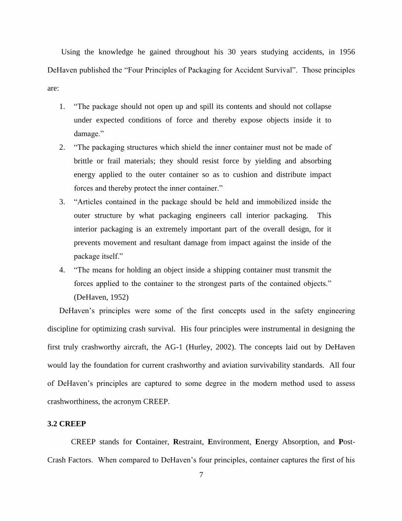
Using the knowledge he gained throughout his 30 years studying accidents, in 1956
DeHaven published the “Four Principles of Packaging for Accident Survival”. Those principles
are:
1. “The package should not open up and spill its contents and should not collapse
under expected conditions of force and thereby expose objects inside it to
damage.”
2. “The packaging structures which shield the inner container must not be made of
brittle or frail materials; they should resist force by yielding and absorbing
energy applied to the outer container so as to cushion and distribute impact
forces and thereby protect the inner container.”
3. “Articles contained in the package should be held and immobilized inside the
outer structure by what packaging engineers call interior packaging. This
interior packaging is an extremely important part of the overall design, for it
prevents movement and resultant damage from impact against the inside of the
package itself.”
4. “The means for holding an object inside a shipping container must transmit the
forces applied to the container to the strongest parts of the contained objects.”
(DeHaven, 1952)
DeHaven’s principles were some of the first concepts used in the safety engineering
discipline for optimizing crash survival. His four principles were instrumental in designing the
first truly crashworthy aircraft, the AG-1 (Hurley, 2002). The concepts laid out by DeHaven
would lay the foundation for current crashworthy and aviation survivability standards. All four
of DeHaven’s principles are captured to some degree in the modern method used to assess
crashworthiness, the acronym CREEP.
3.2 CREEP
CREEP stands for Container, Restraint, Environment, Energy Absorption, and Post-
Crash Factors. When compared to DeHaven’s four principles, container captures the first of his
8
principles, energy absorption relates to his second principle, and restraint correlates to his third
and fourth principles. Under current standards, when analyzing accident survivability, each
component of CREEP is broken down and independently analyzed. For an accident to be
survivable, all aspects of CREEP must be within human tolerances. If any of the components of
CREEP are outside of human tolerances, the accident is either partially or completely non-
survivable. To begin a crashworthy assessment, the accident is analyzed starting with the first
letter in CREEP, “C”, or container.
3.2.1 Container
The concept of container is a derivation of DeHaven’s first principle and deals with the
occupiable space that surrounds the occupants of the aircraft. The aircraft structure “should
possess sufficient strength to prevent intrusion of structure into occupied spaces during a
survivable crash, thus maintaining a protective shell around all occupants” throughout the
accident (Shanahan, 2004). This protective shell is often referred to as survivable space or
survivable volume. If the aircraft’s occupied space breaks apart, crushes, or allows penetration,
survivable space for the occupants will not be maintained and the risk of serious injury or death
significantly increases.
The design of an aircraft is critically important with respect to container. Overall aircraft
structural design, engine configuration, wing configuration, and location of high mass items play
a significant role in survivability. On early aircraft, the engines were mounted in the pusher
configuration which placed propellers and engines behind the pilots which sat in open flight
decks on the front of the aircraft. During crashes the engines would break from their mounts and
displace forward, exposing the pilots to a greater risk of injury. By simply using a tractor engine
configuration, where the engine is mounted in front of the pilot, the high mass of the engine no
9
longer presents the same risk of injury. If a pusher engine is absolutely necessary, design
consideration must be made to ensure that there is enough structural integrity of the engine
mounts to prevent it from displacing forward into the occupied space of the aircraft during a
crash (DeHaven, 1952).
Regarding wing configuration, a high wing airplane can place items such as wing box
structure, fuel cells, and engines above the cabin of the aircraft. If the wing structure isn’t
designed to break away, the high mass items contained on the wings could potentially crush the
cabin, reducing the survivable space available in a crash. If a low or mid-wing configuration
isn’t feasible for an aircraft design, consideration must be taken into hardening the fuselage and
designing the wing structure so that it breaks away reducing the risk of penetrating the cabin
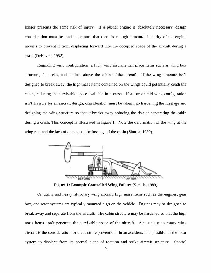
during a crash. This concept is illustrated in figure 1. Note the deformation of the wing at the
wing root and the lack of damage to the fuselage of the cabin (Simula, 1989).
Figure 1: Example Controlled Wing Failure (Simula, 1989)
On utility and heavy lift rotary wing aircraft, high mass items such as the engines, gear
box, and rotor systems are typically mounted high on the vehicle. Engines may be designed to
break away and separate from the aircraft. The cabin structure may be hardened so that the high
mass items don’t penetrate the survivable space of the aircraft. Also unique to rotary wing
aircraft is the consideration for blade strike prevention. In an accident, it is possible for the rotor
system to displace from its normal plane of rotation and strike aircraft structure. Special
10
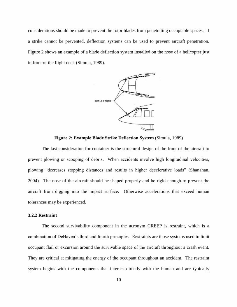
considerations should be made to prevent the rotor blades from penetrating occupiable spaces. If
a strike cannot be prevented, deflection systems can be used to prevent aircraft penetration.
Figure 2 shows an example of a blade deflection system installed on the nose of a helicopter just
in front of the flight deck (Simula, 1989).
Figure 2: Example Blade Strike Deflection System (Simula, 1989)
The last consideration for container is the structural design of the front of the aircraft to
prevent plowing or scooping of debris. When accidents involve high longitudinal velocities,
plowing “decreases stopping distances and results in higher decelerative loads” (Shanahan,
2004). The nose of the aircraft should be shaped properly and be rigid enough to prevent the
aircraft from digging into the impact surface. Otherwise accelerations that exceed human
tolerances may be experienced.
3.2.2 Restraint
The second survivability component in the acronym CREEP is restraint, which is a
combination of DeHaven’s third and fourth principles. Restraints are those systems used to limit
occupant flail or excursion around the survivable space of the aircraft throughout a crash event.
They are critical at mitigating the energy of the occupant throughout an accident. The restraint
system begins with the components that interact directly with the human and are typically
11
textiles that include lap belts, shoulder belts, or full body harnesses. These belts are attached to
seats which are then mounted to aircraft structure. The system of belts, belt to seat interface,
seat, seat to aircraft interface, and aircraft structure establish a total restraint system that is
considered the “occupants tie-down chain” (Lee, 2006). Failure of the occupant tie-down chain
to properly restrain an occupant significantly increases the risk of blunt force trauma due to
excess occupant flail and subsequent contact with aircraft structure.
Blunt force trauma was the primary cause of the fatal injuries experienced in civilian
helicopter accidents between 1993 and 1999. They accounted for 88% of the deaths in the 74
fatal accidents studied. Of the blunt force trauma injuries experienced, 62% of those injuries
were to the head and 61% were to the thoracic region of the body (Taneja & Wiegmann, 2003).
Restraint systems are the most effective ways to limit occupant flail and contact injuries during
an accident. To minimize occupant flail, the restraint system should be designed appropriately
for the location where it is being implemented.
Restraint systems are classified based on how many points of attachment they have with
the belt to seat interface. For example, a two-point restraint system is typically just a simple lap
belt with one attachment point on each side of the occupant’s pelvis. Two-point restraints are
commonly used on passenger commercial aircraft seats. A three-point restraint is commonly
used in modern automobiles, includes a lap belt, and a single shoulder strap. Restraint systems
can vary from two up to five or more points. Modern military aircraft use five-point restraints in
crew seats and the racing industry has utilized up to seven points in their restraint systems. Table
1 summarizes commonly used restraint systems in the aviation industry along with a brief
description of their application (Simula, 1989).
12
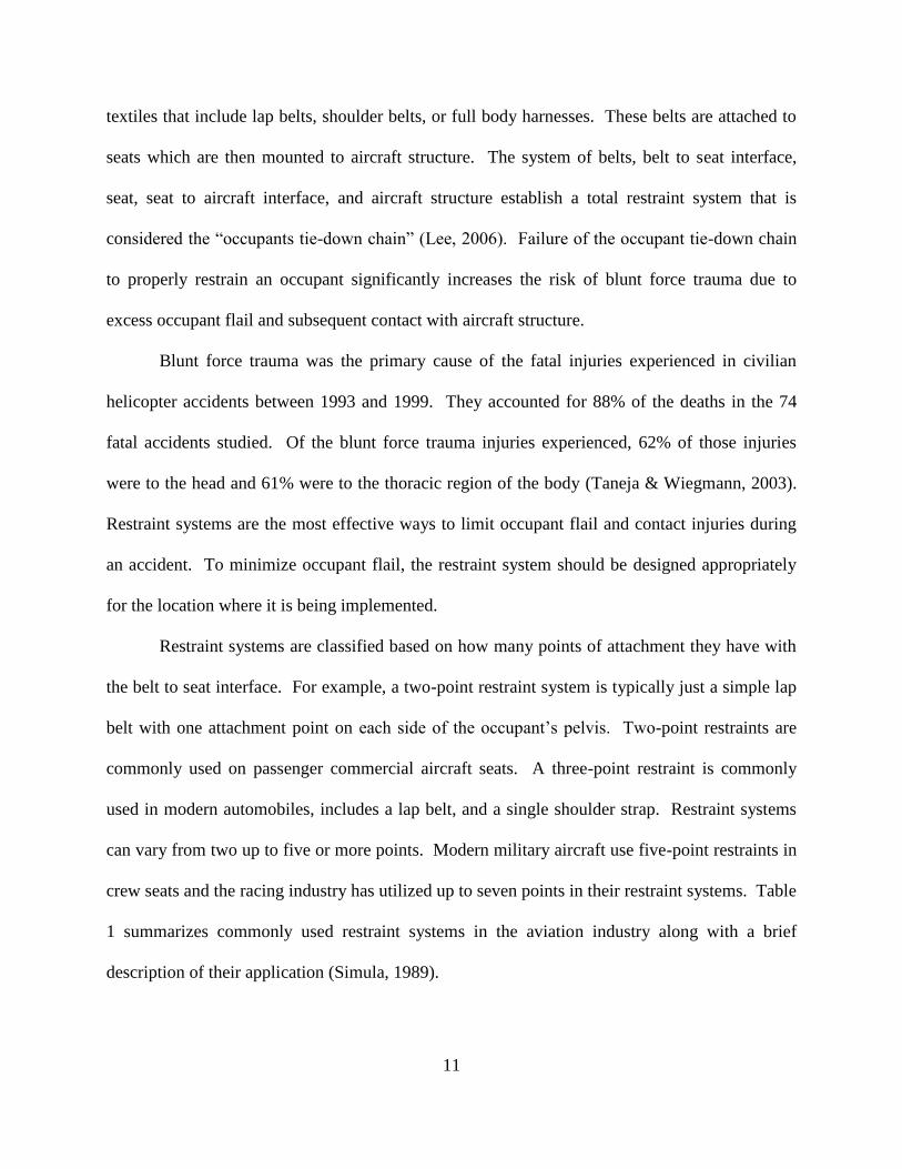
Table 1: Restraint System Types and Application
Restraint Type Description Application
two-point Lap Belt Airline Passenger Seats
three-point Lap Belt, Single Shoulder Belt Automobile Seats, General
Aviation Aircraft Seats
four-point Lap Belt, Two Shoulder Belts
Flight Attendant Seats, Pilot
Seats, Automotive Racing
Seats
five-point Lap Belt, Two Shoulder Belts,
Tie-Down Strap
Military Rotary Wing Pilot
Seats
The more points a restraint system has, the less the occupant will flail and displace
throughout a crash. A two-point restraint is the least effective at minimizing occupant flail.
With just a simple lap belt, an occupant’s head and upper torso are free to displace. As
previously stated, a majority of blunt force trauma injuries experienced during helicopter crashes
are to the head and thoracic region of the body. Due to the use of two-point restraints and the
lack of proper restraint, head injuries are the most commonly experienced serious or fatal injury
observed during general aviation accidents (Davis, 2008). The use of at least a three-point
restraint can significantly decrease occupant flail.
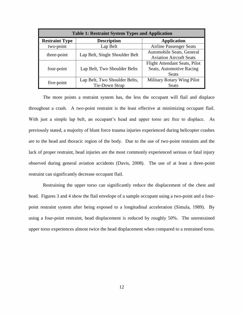
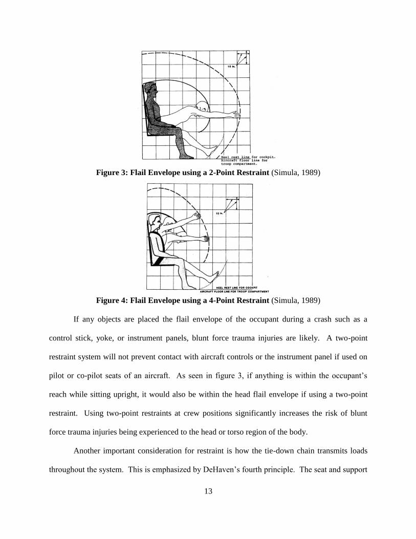
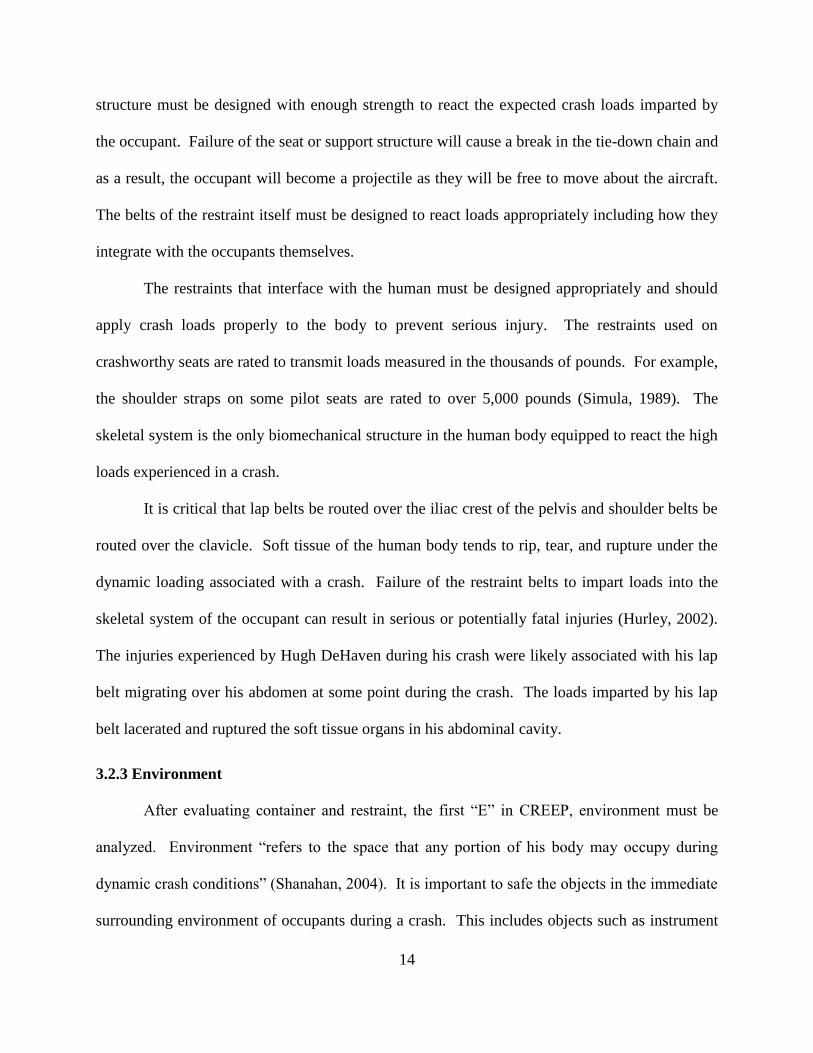
Restraining the upper torso can significantly reduce the displacement of the chest and
head. Figures 3 and 4 show the flail envelope of a sample occupant using a two-point and a four-
point restraint system after being exposed to a longitudinal acceleration (Simula, 1989). By
using a four-point restraint, head displacement is reduced by roughly 50%. The unrestrained
upper torso experiences almost twice the head displacement when compared to a restrained torso.
13
Figure 3: Flail Envelope using a 2-Point Restraint (Simula, 1989)
Figure 4: Flail Envelope using a 4-Point Restraint (Simula, 1989)
If any objects are placed the flail envelope of the occupant during a crash such as a
control stick, yoke, or instrument panels, blunt force trauma injuries are likely. A two-point
restraint system will not prevent contact with aircraft controls or the instrument panel if used on
pilot or co-pilot seats of an aircraft. As seen in figure 3, if anything is within the occupant’s
reach while sitting upright, it would also be within the head flail envelope if using a two-point
restraint. Using two-point restraints at crew positions significantly increases the risk of blunt
force trauma injuries being experienced to the head or torso region of the body.
Another important consideration for restraint is how the tie-down chain transmits loads
throughout the system. This is emphasized by DeHaven’s fourth principle. The seat and support
14
structure must be designed with enough strength to react the expected crash loads imparted by
the occupant. Failure of the seat or support structure will cause a break in the tie-down chain and
as a result, the occupant will become a projectile as they will be free to move about the aircraft.
The belts of the restraint itself must be designed to react loads appropriately including how they
integrate with the occupants themselves.
The restraints that interface with the human must be designed appropriately and should
apply crash loads properly to the body to prevent serious injury. The restraints used on
crashworthy seats are rated to transmit loads measured in the thousands of pounds. For example,
the shoulder straps on some pilot seats are rated to over 5,000 pounds (Simula, 1989). The
skeletal system is the only biomechanical structure in the human body equipped to react the high
loads experienced in a crash.
It is critical that lap belts be routed over the iliac crest of the pelvis and shoulder belts be
routed over the clavicle. Soft tissue of the human body tends to rip, tear, and rupture under the
dynamic loading associated with a crash. Failure of the restraint belts to impart loads into the
skeletal system of the occupant can result in serious or potentially fatal injuries (Hurley, 2002).
The injuries experienced by Hugh DeHaven during his crash were likely associated with his lap
belt migrating over his abdomen at some point during the crash. The loads imparted by his lap
belt lacerated and ruptured the soft tissue organs in his abdominal cavity.
3.2.3 Environment
After evaluating container and restraint, the first “E” in CREEP, environment must be
analyzed. Environment “refers to the space that any portion of his body may occupy during
dynamic crash conditions” (Shanahan, 2004). It is important to safe the objects in the immediate
surrounding environment of occupants during a crash. This includes objects such as instrument
15
consoles, yokes, cyclic controls, passenger tray tables, or any other object the occupant may
strike while restrained during an accident. The delethalization of the occupant’s local
surroundings and proper restraint is critical to ensuring that a survivable environment exists.
Designers should keep hard, rigid objects as far away from occupants as possible. If it is not
possible to keep object out of the flail envelope, considerations should be made to add padding
or design the object to be frangible or break away (Shanahan, 2004).
Flail analysis should be conducted to minimize rigid aircraft structures within an
occupants flail envelope. The prevalence of head injuries during crashes emphasizes the need
for a systematic approach to survivability. While not necessarily a part of the aircraft design,
supplemental systems such as helmets can significantly reduce the risk of head injury and
increase survivability during an accident.
In addition to proper design the occupant’s surroundings, it is also important to ensure
that an occupant’s immediate surroundings are able to support life. Clean, oxygenated air is
necessary to ensure the survivability of occupants throughout the crash event. “Pyrolyzation
products from fires involving electrical insulation and the polyurethane sound-attenuating or
decorative panels can produce inflight incapacitation which reduces survival chances” (United
States, 1991, 24-3). Risk of injury due to smoke exposure is a generally a function of smoke
composition, concentration, and duration of exposure. More specifics on smoke exposure can be
found in section 3.2.5. The effects of smoke exposure can be mitigated by having supplemental
breathing devices available in case an inflight fire breaks out in the aircraft.
3.2.4 Energy Absorption
The second “E” in CREEP represents energy absorption which refers to the process of
dissipating energy in a safe manner throughout a crash. The concept is derivative of DeHaven’s
16
second principle. Kinetic energy (KE) represents a significant source of energy at an aircraft’s
initial impact. As seen in equation 1, KE is proportional to the square of velocity so relatively
small increases in the aircraft velocity result in large increases in KE (Hurley, 2002).
𝐾𝐸 =1
2𝑚 ∗ �⃗� 2 (1)
Where: KE = Kinetic Energy
m = Mass
V= Velocity
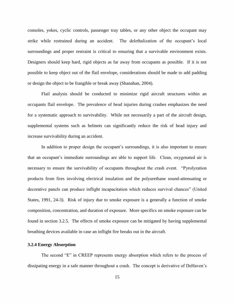
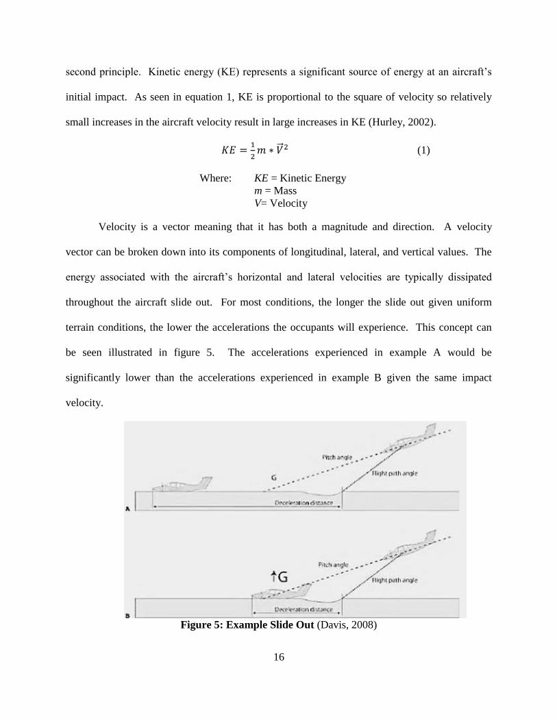
Velocity is a vector meaning that it has both a magnitude and direction. A velocity
vector can be broken down into its components of longitudinal, lateral, and vertical values. The
energy associated with the aircraft’s horizontal and lateral velocities are typically dissipated
throughout the aircraft slide out. For most conditions, the longer the slide out given uniform
terrain conditions, the lower the accelerations the occupants will experience. This concept can
be seen illustrated in figure 5. The accelerations experienced in example A would be
significantly lower than the accelerations experienced in example B given the same impact
velocity.
Figure 5: Example Slide Out (Davis, 2008)
17
The vertical energy however, is not so easy to dissipate as a long slide out isn’t possible.
There isn’t as much space between the bottom of the aircraft and the ground. For vertical
energy, a systematic, comprehensive approach must be taken. Vertical energy absorption is
typically accomplished via the local terrain and aircraft energy absorbing systems. The terrain
the aircraft impacts has the potential to absorb energy. If gouge marks as seen in figure 5 are
present at the initial impact site, the depth of the gouge represents additional displacement and as
a result, energy absorption. Soft surfaces such as sand, soil, or snow will absorb more energy
than harder surfaces such as concrete or rocky terrain. In addition to terrain, energy absorption
can also occur from aircraft deformations and energy absorbing systems.
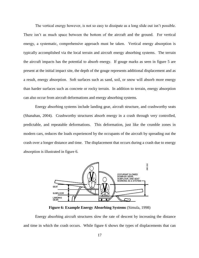
Energy absorbing systems include landing gear, aircraft structure, and crashworthy seats
(Shanahan, 2004). Crashworthy structures absorb energy in a crash through very controlled,
predictable, and repeatable deformations. This deformation, just like the crumble zones in
modern cars, reduces the loads experienced by the occupants of the aircraft by spreading out the
crash over a longer distance and time. The displacement that occurs during a crash due to energy
absorption is illustrated in figure 6.
Figure 6: Example Energy Absorbing Systems (Simula, 1998)
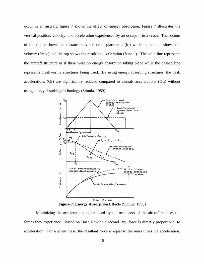
Energy absorbing aircraft structures slow the rate of descent by increasing the distance
and time in which the crash occurs. While figure 6 shows the types of displacements that can
18
occur in an aircraft, figure 7 shows the effect of energy absorption. Figure 7 illustrates the
vertical position, velocity, and acceleration experienced by an occupant in a crash. The bottom
of the figure shows the distance traveled or displacement (ft.) while the middle shows the
velocity (ft/sec) and the top shows the resulting acceleration (ft./sec2). The solid line represents
the aircraft structure as if there were no energy absorption taking place while the dashed line
represents crashworthy structures being used. By using energy absorbing structures, the peak
accelerations (GL) are significantly reduced compared to aircraft accelerations (GM) without
using energy absorbing technology (Simula, 1989).
Figure 7: Energy Absorption Effects (Simula, 1998)
Minimizing the accelerations experienced by the occupants of the aircraft reduces the
forces they experience. Based on Isaac Newton’s second law, force is directly proportional to
acceleration. For a given mass, the resultant force is equal to the mass times the acceleration.
19
Acceleration and force are vector quantities having both a direction and magnitude. Newton’s
second law is represented by equation 2 (Hurley, 2002).
𝐹 = 𝑚 ∗ 𝐴 (2)
Where: F = Force
m = Mass
A= Acceleration
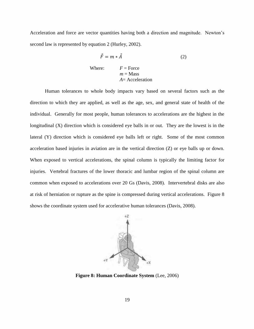
Human tolerances to whole body impacts vary based on several factors such as the
direction to which they are applied, as well as the age, sex, and general state of health of the
individual. Generally for most people, human tolerances to accelerations are the highest in the
longitudinal (X) direction which is considered eye balls in or out. They are the lowest is in the
lateral (Y) direction which is considered eye balls left or right. Some of the most common
acceleration based injuries in aviation are in the vertical direction (Z) or eye balls up or down.
When exposed to vertical accelerations, the spinal column is typically the limiting factor for
injuries. Vertebral fractures of the lower thoracic and lumbar region of the spinal column are
common when exposed to accelerations over 20 Gs (Davis, 2008). Intervertebral disks are also
at risk of herniation or rupture as the spine is compressed during vertical accelerations. Figure 8
shows the coordinate system used for accelerative human tolerances (Davis, 2008).
Figure 8: Human Coordinate System (Lee, 2006)
20
Another consideration to be taken into account when discussing human tolerance to
accelerations, are the biological variabilities that exist between individuals. In general, a
person’s ability to react the loads associated with a crash is directly a function of their
biomechanical ability to react the loads. The musculoskeletal system is the body’s primary
biomechanical mechanism to carry and transmit loads. The strength of an individual’s
musculoskeletal system is a function of factors such as age, sex, and general state of health.
Typically, a young adult will have the highest tolerance to impacts. As bone density decreases
with age, the ability to react loads decreases. With regard to sex, factors such as mass
distribution, bone density, and muscle mass can influence tolerance to impacts. Men typically
have higher muscle mass and bone densities compared to women and as a result can withstand
higher accelerations. General state of health plays a critical role in an individual’s tolerance to
crash loads. Factors such as chronic medical conditions and poor physical conditioning may
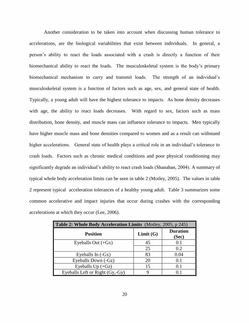
significantly degrade an individual’s ability to react crash loads (Shanahan, 2004). A summary of
typical whole body acceleration limits can be seen in table 2 (Motley, 2005). The values in table
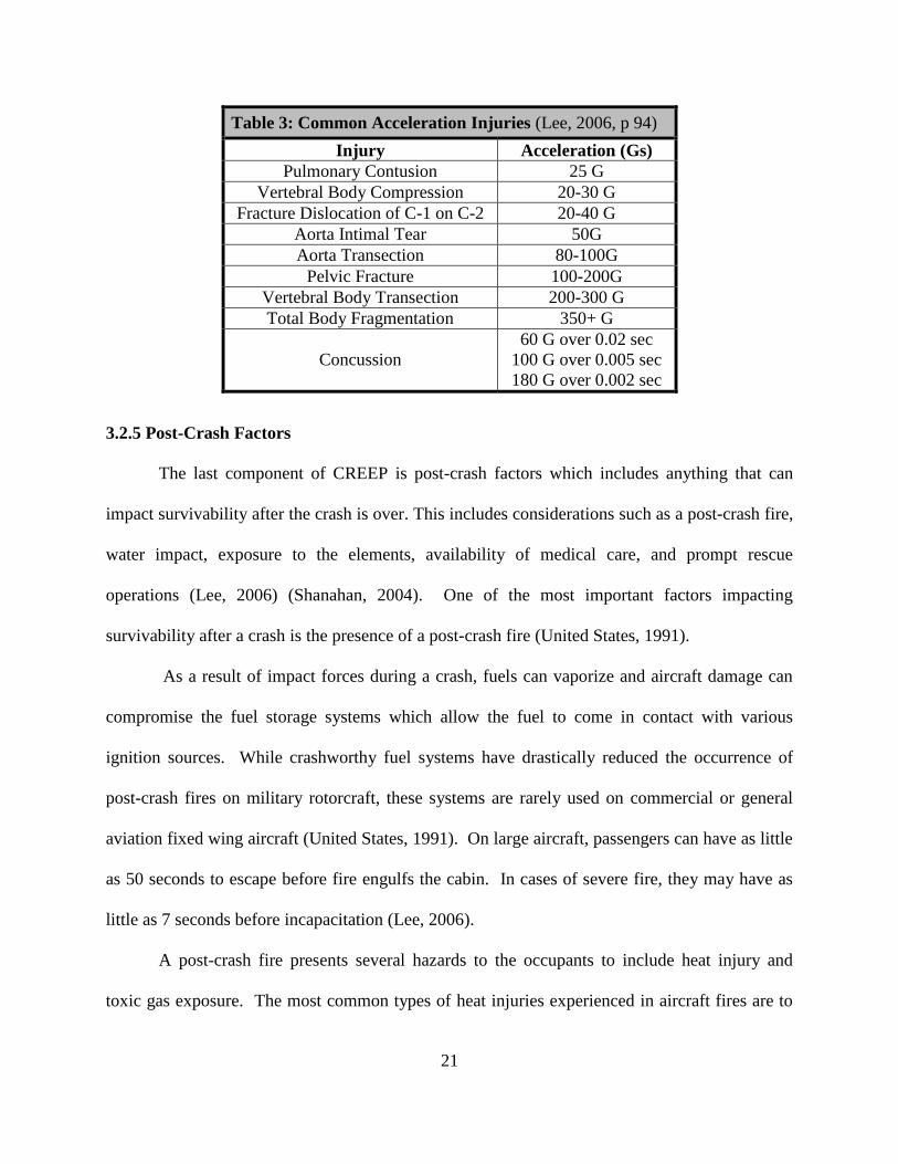
2 represent typical acceleration tolerances of a healthy young adult. Table 3 summarizes some
common accelerative and impact injuries that occur during crashes with the corresponding
accelerations at which they occur (Lee, 2006).
Table 2: Whole Body Acceleration Limits (Motley, 2005, p 245)
Position Limit (G) Duration
(Sec)
Eyeballs Out (+Gx) 45 0.1
25 0.2
Eyeballs In (-Gx) 83 0.04
Eyeballs Down (-Gz) 20 0.1
Eyeballs Up (+Gz) 15 0.1
Eyeballs Left or Right (Gy,-Gy) 9 0.1
21
Table 3: Common Acceleration Injuries (Lee, 2006, p 94)
Injury Acceleration (Gs)
Pulmonary Contusion 25 G
Vertebral Body Compression 20-30 G
Fracture Dislocation of C-1 on C-2 20-40 G
Aorta Intimal Tear 50G
Aorta Transection 80-100G
Pelvic Fracture 100-200G
Vertebral Body Transection 200-300 G
Total Body Fragmentation 350+ G
Concussion
60 G over 0.02 sec
100 G over 0.005 sec
180 G over 0.002 sec
3.2.5 Post-Crash Factors
The last component of CREEP is post-crash factors which includes anything that can
impact survivability after the crash is over. This includes considerations such as a post-crash fire,
water impact, exposure to the elements, availability of medical care, and prompt rescue
operations (Lee, 2006) (Shanahan, 2004). One of the most important factors impacting
survivability after a crash is the presence of a post-crash fire (United States, 1991).
As a result of impact forces during a crash, fuels can vaporize and aircraft damage can
compromise the fuel storage systems which allow the fuel to come in contact with various
ignition sources. While crashworthy fuel systems have drastically reduced the occurrence of
post-crash fires on military rotorcraft, these systems are rarely used on commercial or general
aviation fixed wing aircraft (United States, 1991). On large aircraft, passengers can have as little
as 50 seconds to escape before fire engulfs the cabin. In cases of severe fire, they may have as
little as 7 seconds before incapacitation (Lee, 2006).
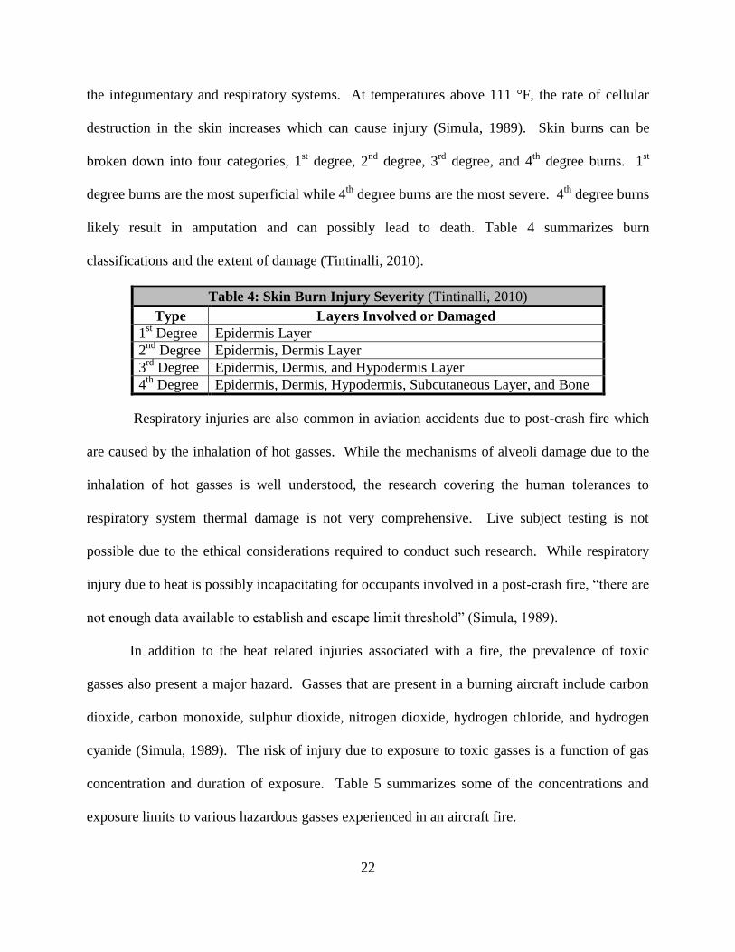
A post-crash fire presents several hazards to the occupants to include heat injury and
toxic gas exposure. The most common types of heat injuries experienced in aircraft fires are to
22
the integumentary and respiratory systems. At temperatures above 111 °F, the rate of cellular
destruction in the skin increases which can cause injury (Simula, 1989). Skin burns can be
broken down into four categories, 1st degree, 2
nd degree, 3
rd degree, and 4
th degree burns. 1
st
degree burns are the most superficial while 4th
degree burns are the most severe. 4th
degree burns
likely result in amputation and can possibly lead to death. Table 4 summarizes burn
classifications and the extent of damage (Tintinalli, 2010).
Table 4: Skin Burn Injury Severity (Tintinalli, 2010)
Type Layers Involved or Damaged
1st Degree Epidermis Layer
2nd
Degree Epidermis, Dermis Layer
3rd
Degree Epidermis, Dermis, and Hypodermis Layer
4th
Degree Epidermis, Dermis, Hypodermis, Subcutaneous Layer, and Bone
Respiratory injuries are also common in aviation accidents due to post-crash fire which
are caused by the inhalation of hot gasses. While the mechanisms of alveoli damage due to the
inhalation of hot gasses is well understood, the research covering the human tolerances to
respiratory system thermal damage is not very comprehensive. Live subject testing is not
possible due to the ethical considerations required to conduct such research. While respiratory
injury due to heat is possibly incapacitating for occupants involved in a post-crash fire, “there are
not enough data available to establish and escape limit threshold” (Simula, 1989).
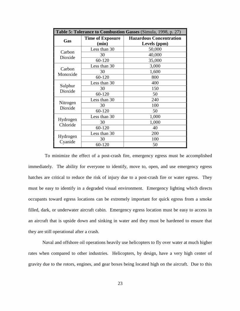
In addition to the heat related injuries associated with a fire, the prevalence of toxic
gasses also present a major hazard. Gasses that are present in a burning aircraft include carbon
dioxide, carbon monoxide, sulphur dioxide, nitrogen dioxide, hydrogen chloride, and hydrogen
cyanide (Simula, 1989). The risk of injury due to exposure to toxic gasses is a function of gas
concentration and duration of exposure. Table 5 summarizes some of the concentrations and
exposure limits to various hazardous gasses experienced in an aircraft fire.
23
Table 5: Tolerance to Combustion Gasses (Simula, 1998, p. 27)
Gas Time of Exposure
(min)
Hazardous Concentration
Levels (ppm)
Carbon
Dioxide
Less than 30 50,000
30 40,000
60-120 35,000
Carbon
Monoxide
Less than 30 3,000
30 1,600
60-120 800
Sulphur
Dioxide
Less than 30 400
30 150
60-120 50
Nitrogen
Dioxide
Less than 30 240
30 100
60-120 50
Hydrogen
Chloride
Less than 30 1,000
30 1,000
60-120 40
Hydrogen
Cyanide
Less than 30 200
30 100
60-120 50
To minimize the effect of a post-crash fire, emergency egress must be accomplished
immediately. The ability for everyone to identify, move to, open, and use emergency egress
hatches are critical to reduce the risk of injury due to a post-crash fire or water egress. They
must be easy to identify in a degraded visual environment. Emergency lighting which directs
occupants toward egress locations can be extremely important for quick egress from a smoke
filled, dark, or underwater aircraft cabin. Emergency egress location must be easy to access in
an aircraft that is upside down and sinking in water and they must be hardened to ensure that
they are still operational after a crash.
Naval and offshore oil operations heavily use helicopters to fly over water at much higher
rates when compared to other industries. Helicopters, by design, have a very high center of
gravity due to the rotors, engines, and gear boxes being located high on the aircraft. Due to this
24
high center of mass, the aircraft are susceptible to roll over (Shanahan, 2004). Egress is of
significant interest, as most helicopters will flip and sink shortly after impact with the water.
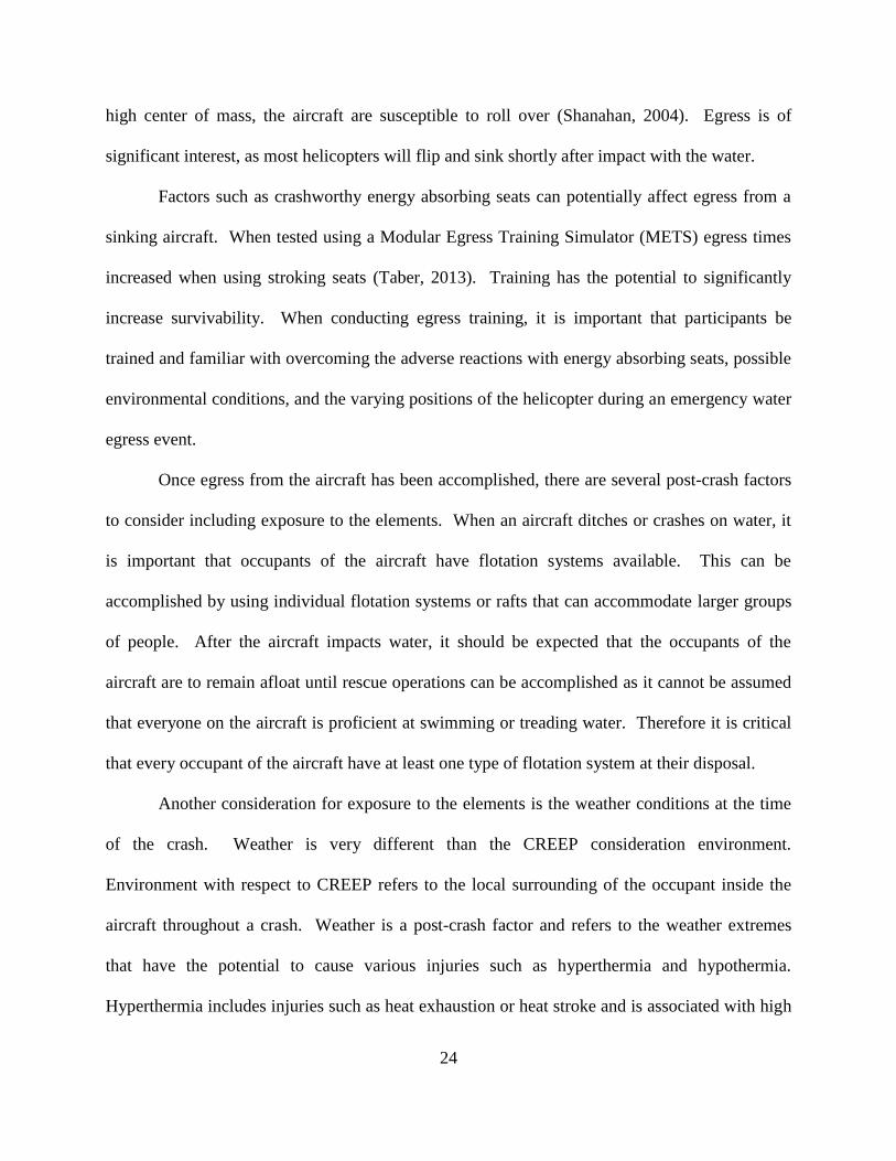
Factors such as crashworthy energy absorbing seats can potentially affect egress from a
sinking aircraft. When tested using a Modular Egress Training Simulator (METS) egress times
increased when using stroking seats (Taber, 2013). Training has the potential to significantly
increase survivability. When conducting egress training, it is important that participants be
trained and familiar with overcoming the adverse reactions with energy absorbing seats, possible
environmental conditions, and the varying positions of the helicopter during an emergency water
egress event.
Once egress from the aircraft has been accomplished, there are several post-crash factors
to consider including exposure to the elements. When an aircraft ditches or crashes on water, it
is important that occupants of the aircraft have flotation systems available. This can be
accomplished by using individual flotation systems or rafts that can accommodate larger groups
of people. After the aircraft impacts water, it should be expected that the occupants of the
aircraft are to remain afloat until rescue operations can be accomplished as it cannot be assumed
that everyone on the aircraft is proficient at swimming or treading water. Therefore it is critical
that every occupant of the aircraft have at least one type of flotation system at their disposal.
Another consideration for exposure to the elements is the weather conditions at the time
of the crash. Weather is very different than the CREEP consideration environment.
Environment with respect to CREEP refers to the local surrounding of the occupant inside the
aircraft throughout a crash. Weather is a post-crash factor and refers to the weather extremes
that have the potential to cause various injuries such as hyperthermia and hypothermia.
Hyperthermia includes injuries such as heat exhaustion or heat stroke and is associated with high
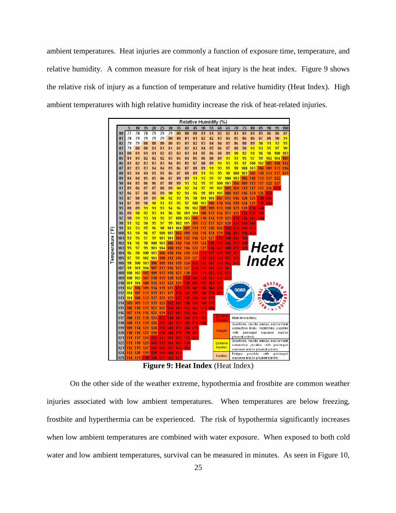
25
ambient temperatures. Heat injuries are commonly a function of exposure time, temperature, and
relative humidity. A common measure for risk of heat injury is the heat index. Figure 9 shows
the relative risk of injury as a function of temperature and relative humidity (Heat Index). High
ambient temperatures with high relative humidity increase the risk of heat-related injuries.
Figure 9: Heat Index (Heat Index)
On the other side of the weather extreme, hypothermia and frostbite are common weather
injuries associated with low ambient temperatures. When temperatures are below freezing,
frostbite and hyperthermia can be experienced. The risk of hypothermia significantly increases
when low ambient temperatures are combined with water exposure. When exposed to both cold
water and low ambient temperatures, survival can be measured in minutes. As seen in Figure 10,
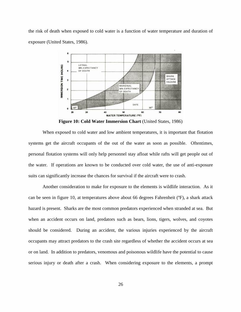
26
the risk of death when exposed to cold water is a function of water temperature and duration of
exposure (United States, 1986).
Figure 10: Cold Water Immersion Chart (United States, 1986)
When exposed to cold water and low ambient temperatures, it is important that flotation
systems get the aircraft occupants of the out of the water as soon as possible. Oftentimes,
personal flotation systems will only help personnel stay afloat while rafts will get people out of
the water. If operations are known to be conducted over cold water, the use of anti-exposure
suits can significantly increase the chances for survival if the aircraft were to crash.
Another consideration to make for exposure to the elements is wildlife interaction. As it
can be seen in figure 10, at temperatures above about 66 degrees Fahrenheit (ºF), a shark attack
hazard is present. Sharks are the most common predators experienced when stranded at sea. But
when an accident occurs on land, predators such as bears, lions, tigers, wolves, and coyotes
should be considered. During an accident, the various injuries experienced by the aircraft
occupants may attract predators to the crash site regardless of whether the accident occurs at sea
or on land. In addition to predators, venomous and poisonous wildlife have the potential to cause
serious injury or death after a crash. When considering exposure to the elements, a prompt
27
emergency rescue and immediate access to medical attention can significantly increase the
probability of survivability.
Prompt access to medical care can significantly reduce the risk of critical injuries
resulting in fatal injuries. Immediately after egress has occurred, and it is safe to do so, it is
important for the medical condition of everyone involved in the crash to be evaluated and first
aid be rendered if possible. If first aid isn’t possible on scene, it is necessary that the victims of
the crash be recovered and medical attention provided immediately.
A fast rescue operation can improve survivability in many ways. The quicker the rescue,
the faster advanced medical care can be given, and the risk of injury due to exposure to the
elements is reduced. For example, on January 15, 2009, US Airways flight 1549 ditched into the
Hudson River shortly after takeoff from LaGuardia Airport. The water temperature was about
36 °F and the ambient temperature was 21 °F. Hypothermia was a serious hazard to the
occupants of the aircraft. However, due to the location of where the aircraft ditched, commuter
ferries were on scene recovering occupants of the aircraft in less than 10 minutes (NTSB, 2009).
Due to the immediate response and recovery efforts, there were no fatalities from US Airways
Flight 1549. Had the aircraft ditched in the Atlantic Ocean where recovery wasn’t measured in
minutes but rather hours, it is likely that many would have perished due to hypothermia.
4.0 Results
With CREEP defined, its focus on the crash is very clear. As mentioned in section 2.0,
there have been several aviation accidents that have occurred throughout history which are not
currently covered by CREEP. While the list of mishaps chosen does not represent an exhaustive
list, each case study emphasizes a deficiency with CREEP. Each case study summarizes the
mishap and reviews the survivability aspects.

28
4.1 Case Studies
4.1.1 Delta Airlines Flight 1288
4.1.1.1 Background
On July 6, 1996, a McDonnell Douglas MD-88 experienced an engine failure during
takeoff from Pensacola Regional Airport, Florida. The flight was conducted under Part 121
scheduled, air carrier operations and was operated as Delta Airlines flight 1288. There were a
total of 144 people onboard the aircraft of which two received fatal injuries, two received serious
injuries, and three received minor injuries.
During the aircraft’s takeoff roll, the number 1 engine experienced an uncontained failure
which resulted in significant damage to the fuselage. Without getting airborne, the crew aborted
takeoff and stopped roughly 1400 ft. down the runway. After the aircraft came to rest, the flight
crew initiated an emergency evacuation. The accident aircraft can be seen in figure 11; note the
damage to the fuselage.
Figure 11: Damage to MD-88 Fuselage (NTSB, 1997)
The source of the engine failure was determined to be a fatigue failure of the compressor
fan hub which was caused by a manufacturing defect. A drilling process during manufacture
created an altered microstructure within the part which went undetected. The altered
29
microstructure produced a stress concentration which would ultimately form a fatigue crack.
The inspection techniques employed by the engine manufacturer and Delta did not detect the
fatigue crack. On the accident flight, the fatigue crack propagated ultimately causing failure of
the entire assembly. The failed compressor hub assembly and other engine components escaped
the engine case and penetrated the fuselage of the aircraft resulting in an uncontained engine
failure (NTSB, 1997).
4.1.1.2 Survivability Considerations
Of the 144 people onboard the aircraft, two passengers were killed in the accident.
Emergency evacuation was initiated immediately after the aircraft came to rest in which some
passengers egressed using the emergency slides. Once the aircraft was determined to be safe and
there was no risk of fire, emergency egress was stopped to reduce the risk of further injury to the
passengers and crew. Roughly 20 to 30 minutes after the accident, air stairs were brought to the
aircraft and the remaining passengers and crew disembarked without any further injuries.
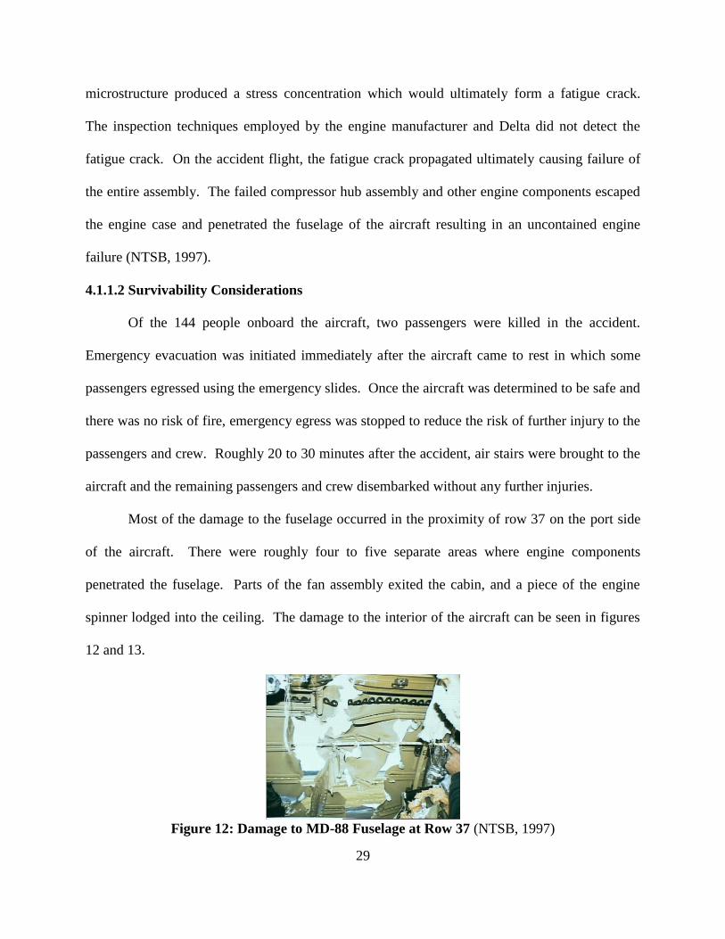
Most of the damage to the fuselage occurred in the proximity of row 37 on the port side
of the aircraft. There were roughly four to five separate areas where engine components
penetrated the fuselage. Parts of the fan assembly exited the cabin, and a piece of the engine
spinner lodged into the ceiling. The damage to the interior of the aircraft can be seen in figures
12 and 13.
Figure 12: Damage to MD-88 Fuselage at Row 37 (NTSB, 1997)
30
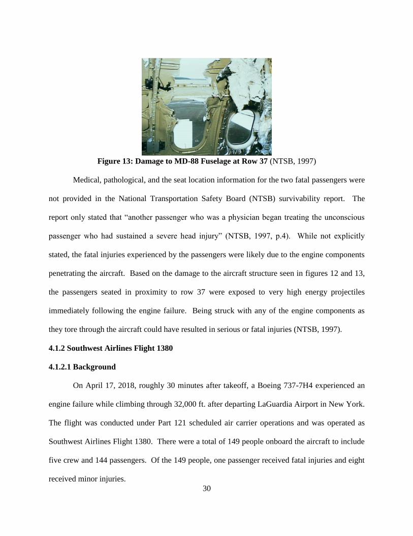
Figure 13: Damage to MD-88 Fuselage at Row 37 (NTSB, 1997)
Medical, pathological, and the seat location information for the two fatal passengers were
not provided in the National Transportation Safety Board (NTSB) survivability report. The
report only stated that “another passenger who was a physician began treating the unconscious
passenger who had sustained a severe head injury” (NTSB, 1997, p.4). While not explicitly
stated, the fatal injuries experienced by the passengers were likely due to the engine components
penetrating the aircraft. Based on the damage to the aircraft structure seen in figures 12 and 13,
the passengers seated in proximity to row 37 were exposed to very high energy projectiles
immediately following the engine failure. Being struck with any of the engine components as
they tore through the aircraft could have resulted in serious or fatal injuries (NTSB, 1997).
4.1.2 Southwest Airlines Flight 1380
4.1.2.1 Background
On April 17, 2018, roughly 30 minutes after takeoff, a Boeing 737-7H4 experienced an
engine failure while climbing through 32,000 ft. after departing LaGuardia Airport in New York.
The flight was conducted under Part 121 scheduled air carrier operations and was operated as
Southwest Airlines Flight 1380. There were a total of 149 people onboard the aircraft to include
five crew and 144 passengers. Of the 149 people, one passenger received fatal injuries and eight
received minor injuries.

31
While climbing to cruising altitude during initial climb out, the number one engine
experienced a failure which caused pieces of the engine inlet and fan cowling to separate the
aircraft. Part of the engine cowling struck the fuselage causing one of the cabin windows to fail
and depart the aircraft. After separation of the cabin window, rapid decompression of the
fuselage occurred. Due to the engine failure and loss of cabin pressure, the crew conducted an
emergency descent and successfully landed at Philadelphia International Airport roughly 17
minutes after the engine failure.
The engine failure was determined to be caused by a low-cycle fatigue crack that formed
in the number 13 fan blade which ultimately caused the blade to fail and separate inflight. Once
the fan blade separated, it impacted the engine’s fan case in a critical structural location causing
it to fail. Once the fan case failed, it separated the aircraft striking the port side wing, fuselage,
and horizontal stabilizer (NTSB, 2019).
4.1.2.2 Survivability Considerations
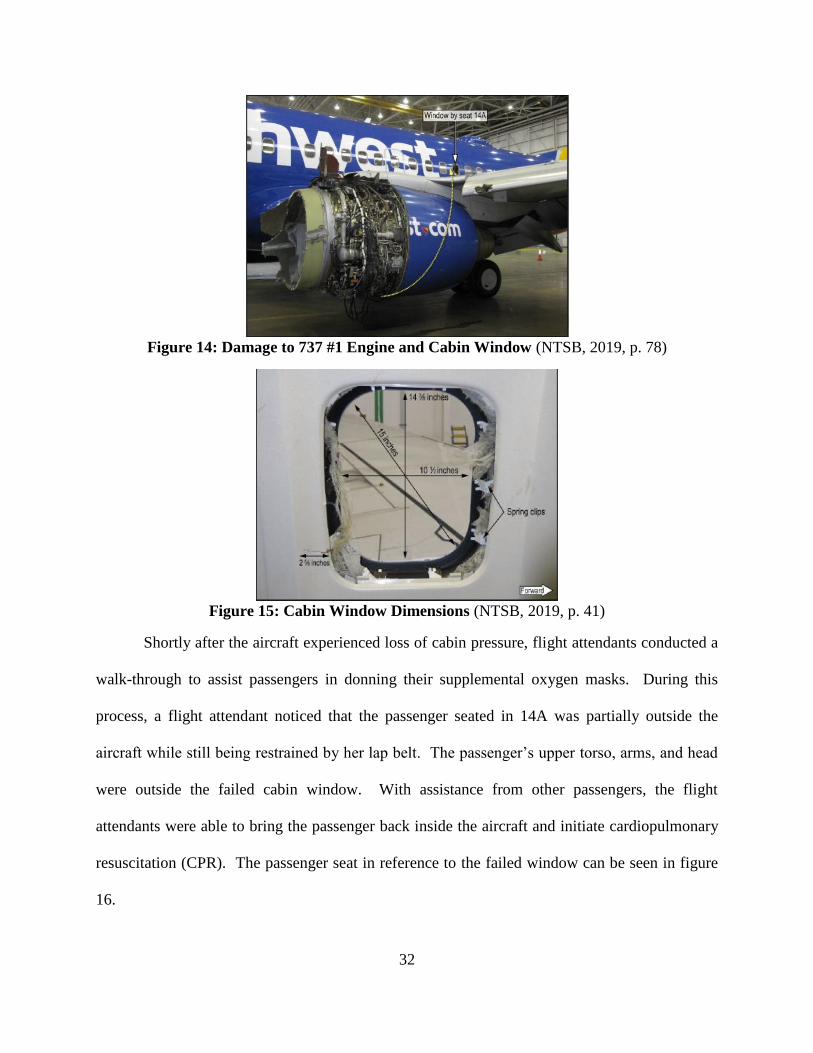
The only fatality was a passenger seated in 14A which was adjacent to the failed cabin
window. The window measured 10.5 inches horizontally, 14.375 inches vertically, and 15
inches diagonally. The accident aircraft and cabin window can be seen in figures 14 and 15.
Note the location of the failed window in relation to the failed engine cowling.
32
Figure 14: Damage to 737 #1 Engine and Cabin Window (NTSB, 2019, p. 78)
Figure 15: Cabin Window Dimensions (NTSB, 2019, p. 41)
Shortly after the aircraft experienced loss of cabin pressure, flight attendants conducted a
walk-through to assist passengers in donning their supplemental oxygen masks. During this
process, a flight attendant noticed that the passenger seated in 14A was partially outside the
aircraft while still being restrained by her lap belt. The passenger’s upper torso, arms, and head
were outside the failed cabin window. With assistance from other passengers, the flight
attendants were able to bring the passenger back inside the aircraft and initiate cardiopulmonary
resuscitation (CPR). The passenger seat in reference to the failed window can be seen in figure
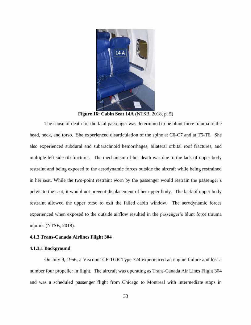
16.
33
Figure 16: Cabin Seat 14A (NTSB, 2018, p. 5)
The cause of death for the fatal passenger was determined to be blunt force trauma to the
head, neck, and torso. She experienced disarticulation of the spine at C6-C7 and at T5-T6. She
also experienced subdural and subarachnoid hemorrhages, bilateral orbital roof fractures, and
multiple left side rib fractures. The mechanism of her death was due to the lack of upper body
restraint and being exposed to the aerodynamic forces outside the aircraft while being restrained
in her seat. While the two-point restraint worn by the passenger would restrain the passenger’s
pelvis to the seat, it would not prevent displacement of her upper body. The lack of upper body
restraint allowed the upper torso to exit the failed cabin window. The aerodynamic forces
experienced when exposed to the outside airflow resulted in the passenger’s blunt force trauma
injuries (NTSB, 2018).
4.1.3 Trans-Canada Airlines Flight 304
4.1.3.1 Background
On July 9, 1956, a Viscount CF-TGR Type 724 experienced an engine failure and lost a
number four propeller in flight. The aircraft was operating as Trans-Canada Air Lines Flight 304
and was a scheduled passenger flight from Chicago to Montreal with intermediate stops in
34
Toronto and Ottawa. The aircraft had 31 passengers and four crew onboard. While flying in the
vicinity of Flat Rock, Michigan, an engine issue developed which caused the crew to conduct an
emergency descent. While descending, the propeller from the number four engine broke free
from the hub and blades passed through the fuselage, killing one passenger.
The cause of the propeller failure was due to over speed. While in cruise, the crew
noticed a drop in engine Revolutions per Minute (RPM) on the number four engine from a
nominal speed of 13,600 RPM. Shortly after, the engine returned to normal speed and remained
there for about five minutes before it increased rapidly to about 14,000 RPM. The crew
unsuccessfully attempted to feather the propeller so they decoupled the propeller from the engine
and shut down the number four engine. They declared an emergency and conducted an
emergency descent at near maximum airspeed. During the emergency descent the aircrew could
hear the over speed of the wind-milling propeller before it failed at about 9,000 ft. (CAB, 1957).
4.1.3.2 Survivability Considerations
When the propeller failed, blades tore through the fuselage of the aircraft killing one
passenger and injuring six others to include one of the crew. There was major cabin damage in
the area of the two forward most rows of seats caused by the failed propeller. Roughly ten
minutes after the emergency descent started and the propeller failed, the aircraft landed safely in
Winsor, Ontario without further incident. There was no medical or pathological information
provided in the Civil Aeronautics Board (CAB) report for the injuries sustained by the
passengers and it was only noted that one crew member received a minor head injury (CAB,
1957).
There were no photographs provided by the CAB for the accident aircraft. The exact
extent of the damage to the fuselage caused by the propeller wasn’t clearly documented; it was
35
only noted as “major” (CAB, 1957). Once the propeller failed and penetrated the aircraft,
occupants were exposed to very high kinetic energy projectiles. Being struck by any of the
projectiles could have resulted in serious or fatal injuries.
4.1.4 British Airtours Flight 28M
4.1.4.1 Background
On August 22, 1985, a Boeing 737-236 aircraft experienced an uncontained engine
failure to its number one engine during takeoff from Manchester International Airport in the
United Kingdom. The aircraft was operating as British Airtours Flight 28M and was carrying
131 passengers and six crew. Before becoming airborne, roughly 30 seconds after the start of its
takeoff roll, the engine failed as the aircraft achieved a maximum airspeed of 125 knots.
Immediately after the engine failure the crew aborted takeoff informed Air Traffic Control
(ATC) of their situation. Pieces of the engine struck the left wing and punctured a fuel tank
access panel causing fuel to leak from the wing tank. The leaking fuel contacted the failed
engine and ignited. As the aircraft was still slowing down, ATC confirmed that the aircraft was
on fire, and the captain informed the crew that they would need to evacuate from the right side of
the aircraft.
When the aircraft came to rest, the captain stopped the aircraft such that winds from 250
degrees at roughly seven knots, carried the fire onto the fuselage. Shortly after coming to rest,
fire and smoke filled the cabin. The aft right side door was opened just prior to the aircraft
coming to rest accelerating the rate at which the cabin filled with smoke. Emergency egress was
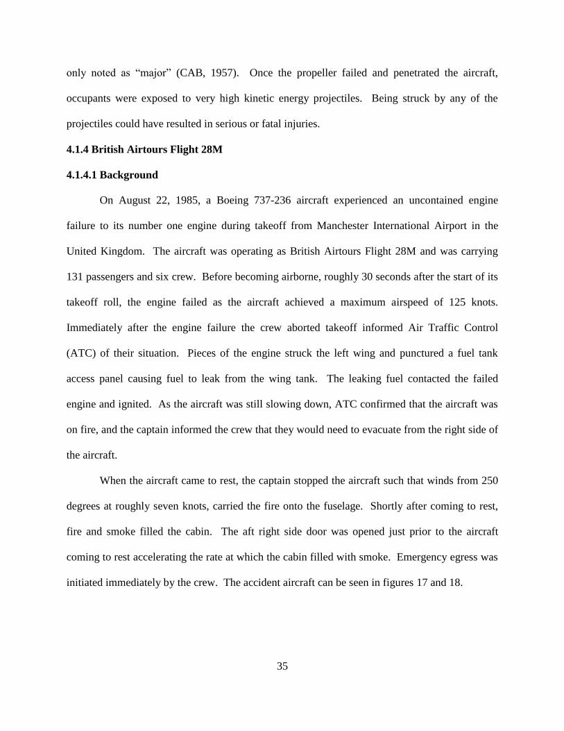
initiated immediately by the crew. The accident aircraft can be seen in figures 17 and 18.
36
Figure 17: Boeing 737 Fire Damage (AAIB, 1989, p. 3)
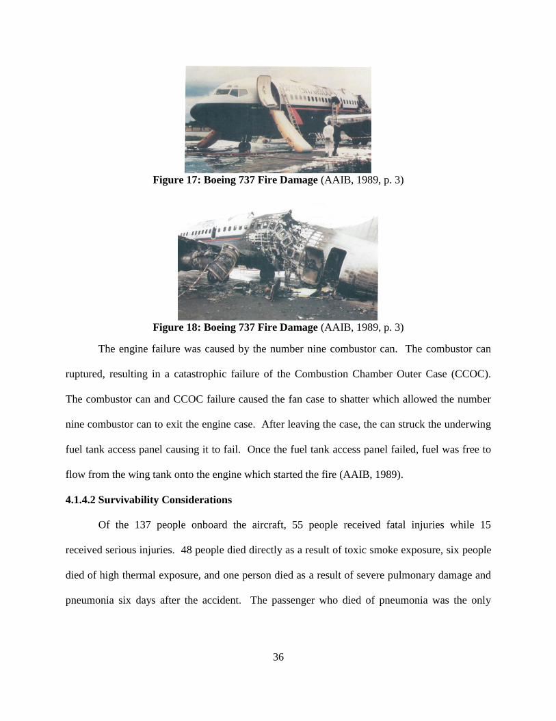
Figure 18: Boeing 737 Fire Damage (AAIB, 1989, p. 3)
The engine failure was caused by the number nine combustor can. The combustor can
ruptured, resulting in a catastrophic failure of the Combustion Chamber Outer Case (CCOC).
The combustor can and CCOC failure caused the fan case to shatter which allowed the number
nine combustor can to exit the engine case. After leaving the case, the can struck the underwing
fuel tank access panel causing it to fail. Once the fuel tank access panel failed, fuel was free to
flow from the wing tank onto the engine which started the fire (AAIB, 1989).
4.1.4.2 Survivability Considerations
Of the 137 people onboard the aircraft, 55 people received fatal injuries while 15
received serious injuries. 48 people died directly as a result of toxic smoke exposure, six people
died of high thermal exposure, and one person died as a result of severe pulmonary damage and
pneumonia six days after the accident. The passenger who died of pneumonia was the only
37
fatality recovered still alive from the aircraft by first responders. The remaining 54 fatalities died
while still in the aircraft before being recovered.
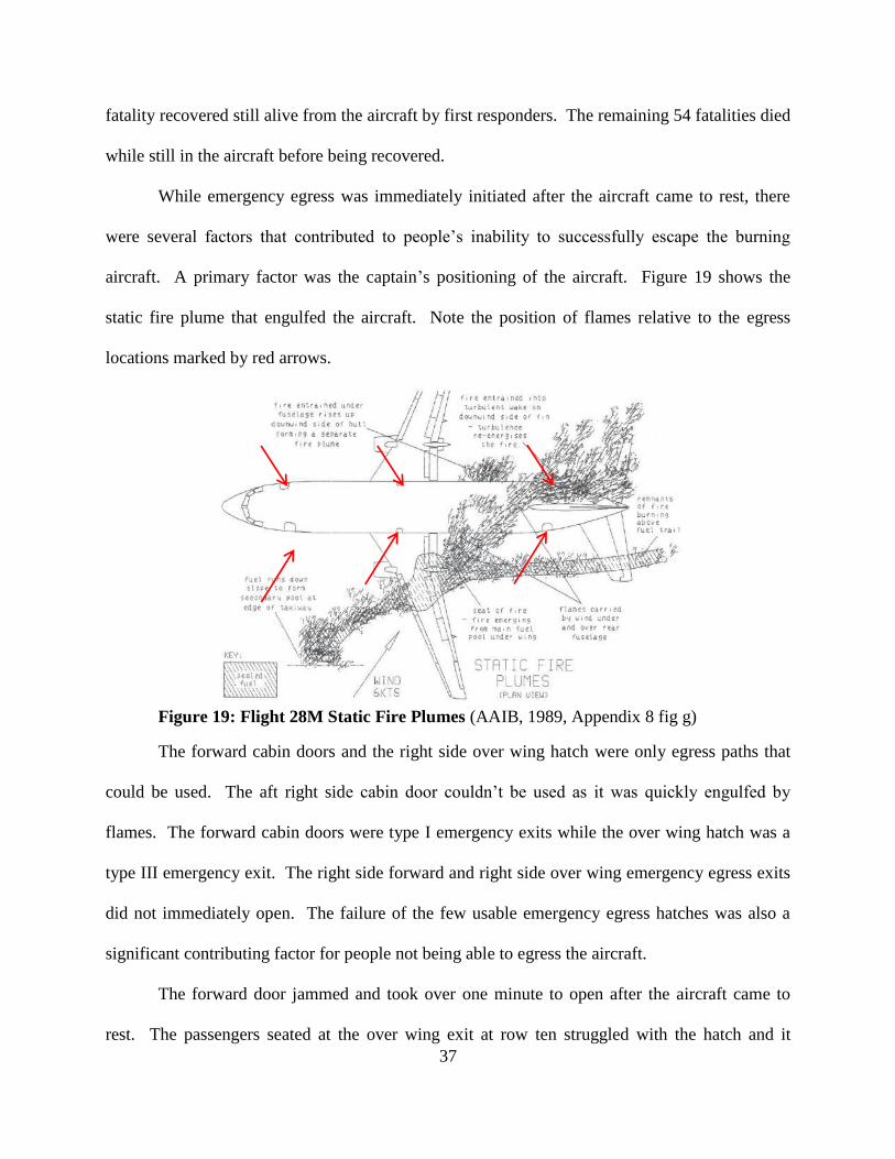
While emergency egress was immediately initiated after the aircraft came to rest, there
were several factors that contributed to people’s inability to successfully escape the burning
aircraft. A primary factor was the captain’s positioning of the aircraft. Figure 19 shows the
static fire plume that engulfed the aircraft. Note the position of flames relative to the egress
locations marked by red arrows.
Figure 19: Flight 28M Static Fire Plumes (AAIB, 1989, Appendix 8 fig g)
The forward cabin doors and the right side over wing hatch were only egress paths that
could be used. The aft right side cabin door couldn’t be used as it was quickly engulfed by
flames. The forward cabin doors were type I emergency exits while the over wing hatch was a
type III emergency exit. The right side forward and right side over wing emergency egress exits
did not immediately open. The failure of the few usable emergency egress hatches was also a
significant contributing factor for people not being able to egress the aircraft.
The forward door jammed and took over one minute to open after the aircraft came to
rest. The passengers seated at the over wing exit at row ten struggled with the hatch and it
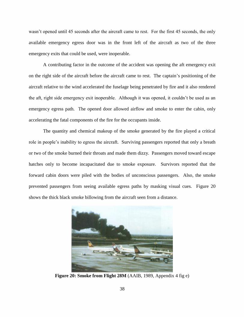
38
wasn’t opened until 45 seconds after the aircraft came to rest. For the first 45 seconds, the only
available emergency egress door was in the front left of the aircraft as two of the three
emergency exits that could be used, were inoperable.
A contributing factor in the outcome of the accident was opening the aft emergency exit
on the right side of the aircraft before the aircraft came to rest. The captain’s positioning of the
aircraft relative to the wind accelerated the fuselage being penetrated by fire and it also rendered
the aft, right side emergency exit inoperable. Although it was opened, it couldn’t be used as an
emergency egress path. The opened door allowed airflow and smoke to enter the cabin, only
accelerating the fatal components of the fire for the occupants inside.
The quantity and chemical makeup of the smoke generated by the fire played a critical
role in people’s inability to egress the aircraft. Surviving passengers reported that only a breath
or two of the smoke burned their throats and made them dizzy. Passengers moved toward escape
hatches only to become incapacitated due to smoke exposure. Survivors reported that the
forward cabin doors were piled with the bodies of unconscious passengers. Also, the smoke
prevented passengers from seeing available egress paths by masking visual cues. Figure 20
shows the thick black smoke billowing from the aircraft seen from a distance.
Figure 20: Smoke from Flight 28M (AAIB, 1989, Appendix 4 fig e)
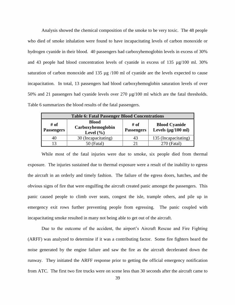
39
Analysis showed the chemical composition of the smoke to be very toxic. The 48 people
who died of smoke inhalation were found to have incapacitating levels of carbon monoxide or
hydrogen cyanide in their blood. 40 passengers had carboxyhemoglobin levels in excess of 30%
and 43 people had blood concentration levels of cyanide in excess of 135 µg/100 ml. 30%
saturation of carbon monoxide and 135 µg /100 ml of cyanide are the levels expected to cause
incapacitation. In total, 13 passengers had blood carboxyhemoglobin saturation levels of over
50% and 21 passengers had cyanide levels over 270 µg/100 ml which are the fatal thresholds.
Table 6 summarizes the blood results of the fatal passengers.
Table 6: Fatal Passenger Blood Concentrations
# of
Passengers
Blood
Carboxyhemoglobin
Level (%)
# of
Passengers
Blood Cyanide
Levels (µg/100 ml)
40 30 (Incapacitating) 43 135 (Incapacitating)
13 50 (Fatal) 21 270 (Fatal)
While most of the fatal injuries were due to smoke, six people died from thermal
exposure. The injuries sustained due to thermal exposure were a result of the inability to egress
the aircraft in an orderly and timely fashion. The failure of the egress doors, hatches, and the
obvious signs of fire that were engulfing the aircraft created panic amongst the passengers. This
panic caused people to climb over seats, congest the isle, trample others, and pile up in
emergency exit rows further preventing people from egressing. The panic coupled with
incapacitating smoke resulted in many not being able to get out of the aircraft.
Due to the outcome of the accident, the airport’s Aircraft Rescue and Fire Fighting
(ARFF) was analyzed to determine if it was a contributing factor. Some fire fighters heard the
noise generated by the engine failure and saw the fire as the aircraft decelerated down the
runway. They initiated the ARFF response prior to getting the official emergency notification
from ATC. The first two fire trucks were on scene less than 30 seconds after the aircraft came to
40
rest and both carried 50 kgs of Halon BCF, 817 liters of water, and 73 liters of Aqueous Film
Forming Foam (AFFF). Another two fire trucks arrived roughly 30 seconds after the first two
and they carried 100 kgs of Halon BCF, 9,080 liters of water, 1,067 liters of AFFF in one truck
and 13,620 liters of water, and 1,634 liters of AFFF in the other. The fifth and last fire truck
arrived on scene four to five minutes later as it had to be retrieved from the airfield’s paint shop.
It carried 13,620 liters of water, and 1,634 liters of AFFF.
While there were no issues with the initial response, there were problems resupplying the
firefighting effort. Water trucks carrying 7,272 liters of water were delayed at entry control
points as police were not staged properly to escort them to the accident site. There was also
construction on going with the airport’s water hydrant system which caused about a 10 minute
delay in obtaining resupply water.
Seven minutes after the accident started, firefighters attempted to enter the aircraft to look
for survivors but an explosion threw one of them from the aircraft. It was determined that
firefighters would not enter the aircraft until a water resupply could be reestablished due to the
unsafe conditions. After the water resupply was accomplished, fire fighters entered the aircraft
to look for survivors. After about 33 minutes, firefighters only found one person still alive but
that person died at the hospital six days later.
The investigation found that the ARFF response met all requirements and regulations for
operating at Manchester Airport. The response and capability of ARFF exceeded the minimum
standards required for the operation of a Boeing 737. The speed of the initial response was less
than 30 seconds and the fire hydrant being tuned off for maintenance was not found to be a
significant contributor to the outcome of the accident. While communication and tactics were
found to contribute to the accident, the ARFF response did not violate any regulations or deviate
41
from established firefighting tactics. Even with the acceptable ARFF response, all of the fatal
injuries experienced in this accident were associated with being exposed to fire and the products
produced by the fire (AAIB, 1989).
4.1.5 Red Bull Stratos Project
4.1.5.1 Background
The Red Bull Stratos Project was a flight test program privately funded by the company
Red Bull and carried out between 2005 and 2012. The project involved parachutist Felix
Baumgartner jumping from both aircraft and helium filled balloons from varying altitudes. On
October 14, 2012, the program culminated in Felix jumping from an altitude of 127,852 ft. and
achieved a maximum speed of 843.6 mph (Mach 1.25) during his descent. The program broke
the world records for the highest manned balloon ascent of 128,178 ft., the highest jump altitude,
and the maximum vertical speed achieved by someone in freefall. Felix was the first person to
exceed the speed of sound in freefall without the protection or propulsion of a vehicle. Figure 21
shows the parachutist just prior to jumping from the capsule.
Figure 21: Red Bull Stratos Jump (Red Bull, 2020)
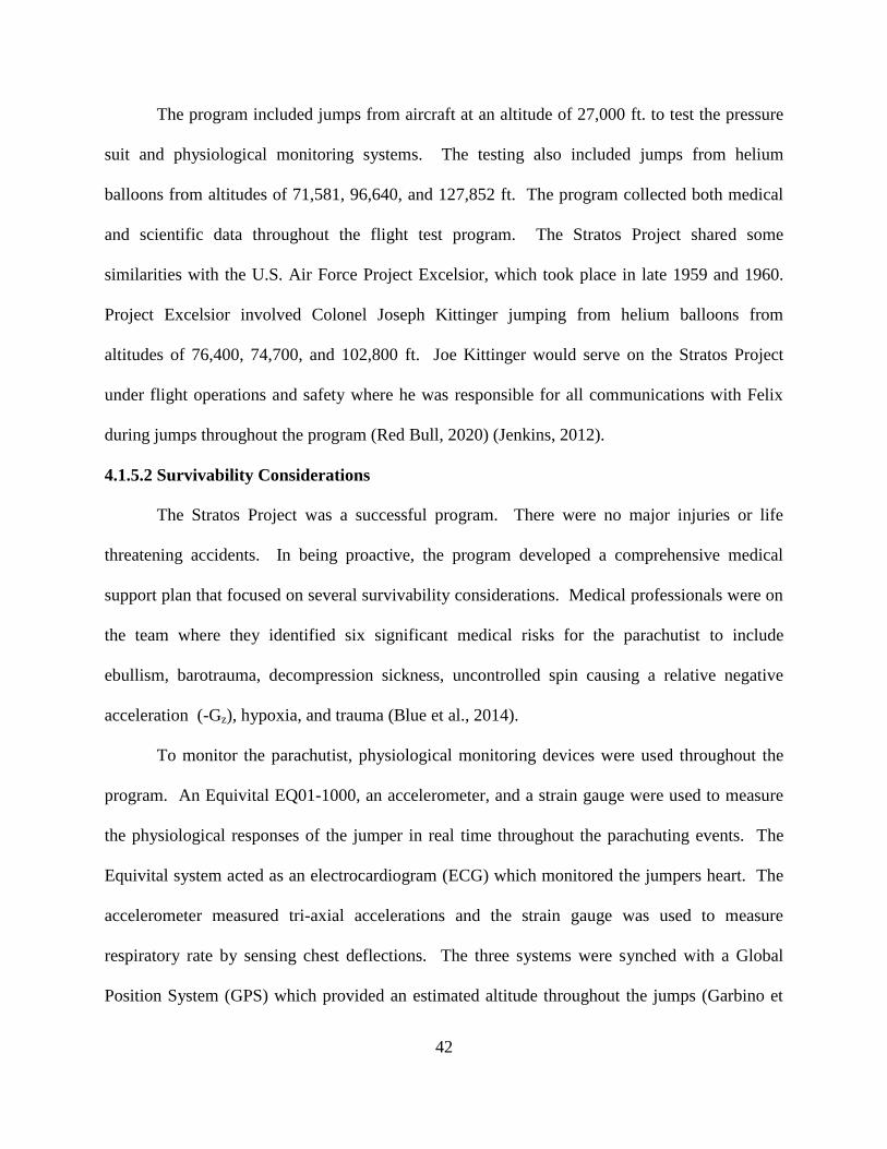
42
The program included jumps from aircraft at an altitude of 27,000 ft. to test the pressure
suit and physiological monitoring systems. The testing also included jumps from helium
balloons from altitudes of 71,581, 96,640, and 127,852 ft. The program collected both medical
and scientific data throughout the flight test program. The Stratos Project shared some
similarities with the U.S. Air Force Project Excelsior, which took place in late 1959 and 1960.
Project Excelsior involved Colonel Joseph Kittinger jumping from helium balloons from
altitudes of 76,400, 74,700, and 102,800 ft. Joe Kittinger would serve on the Stratos Project
under flight operations and safety where he was responsible for all communications with Felix
during jumps throughout the program (Red Bull, 2020) (Jenkins, 2012).
4.1.5.2 Survivability Considerations
The Stratos Project was a successful program. There were no major injuries or life
threatening accidents. In being proactive, the program developed a comprehensive medical
support plan that focused on several survivability considerations. Medical professionals were on
the team where they identified six significant medical risks for the parachutist to include
ebullism, barotrauma, decompression sickness, uncontrolled spin causing a relative negative
acceleration (-Gz), hypoxia, and trauma (Blue et al., 2014).
To monitor the parachutist, physiological monitoring devices were used throughout the
program. An Equivital EQ01-1000, an accelerometer, and a strain gauge were used to measure
the physiological responses of the jumper in real time throughout the parachuting events. The
Equivital system acted as an electrocardiogram (ECG) which monitored the jumpers heart. The
accelerometer measured tri-axial accelerations and the strain gauge was used to measure
respiratory rate by sensing chest deflections. The three systems were synched with a Global
Position System (GPS) which provided an estimated altitude throughout the jumps (Garbino et

43
al, 2014). All of the physiological monitoring systems were integrated into the pressure suit
which can be seen in figure 22.
Figure 22: Pressure Suit Worn by Felix Baumgartner (Red Bull, 2020)
Due to the nature of the test program, the medical plan outlined six discrete phases of
flight that presented unique medical concerns. The six phases are summarized in table 7.
Table 7: Stratos Phases of Flight and Medical Risks (Blue et al., 2014, p. 533)
Phase Activity Medical Concern
1 Pre-breathe 100% oxygen pre-breathe, fire risk
2 Capsule Ingress Limited visibility, fall risk, maintenance of gas supply lines
3 Launch
Tethered balloon precision release, crane/capsule acceleration,
release failure with capsule fail, occupant trauma, support team
injury
4 Early Ascent <4,000 ft. AGL: balloon failure with limited time for parachute
opening, high velocity traumatic landing
5 Ascent/Freefall
>4,000 ft. AGL: loss of pressure with hypoxia, decompression
sickness, ebullism, flat spin during descent and freefall, traumatic
landing
6 Recovery Hazardous terrain in landing zone, wildlife, traumatic landing
To reduce the risk of decompression sickness, the parachutist would pre-breathe 100%
oxygen for two hours prior to the balloon launches. This would help rid the blood stream of
dissolved inert gasses reducing the risk of decompression sickness if rapid decompression
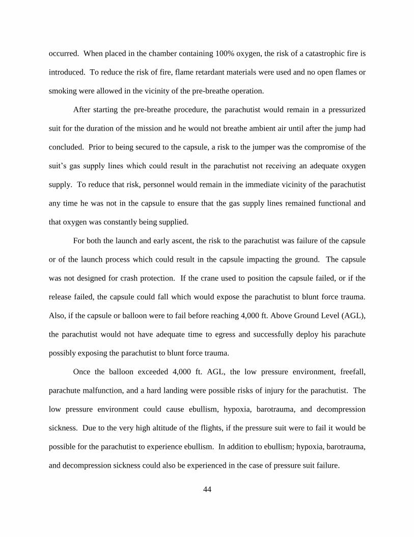
44
occurred. When placed in the chamber containing 100% oxygen, the risk of a catastrophic fire is
introduced. To reduce the risk of fire, flame retardant materials were used and no open flames or
smoking were allowed in the vicinity of the pre-breathe operation.
After starting the pre-breathe procedure, the parachutist would remain in a pressurized
suit for the duration of the mission and he would not breathe ambient air until after the jump had
concluded. Prior to being secured to the capsule, a risk to the jumper was the compromise of the
suit’s gas supply lines which could result in the parachutist not receiving an adequate oxygen
supply. To reduce that risk, personnel would remain in the immediate vicinity of the parachutist
any time he was not in the capsule to ensure that the gas supply lines remained functional and
that oxygen was constantly being supplied.
For both the launch and early ascent, the risk to the parachutist was failure of the capsule
or of the launch process which could result in the capsule impacting the ground. The capsule
was not designed for crash protection. If the crane used to position the capsule failed, or if the
release failed, the capsule could fall which would expose the parachutist to blunt force trauma.
Also, if the capsule or balloon were to fail before reaching 4,000 ft. Above Ground Level (AGL),
the parachutist would not have adequate time to egress and successfully deploy his parachute
possibly exposing the parachutist to blunt force trauma.
Once the balloon exceeded 4,000 ft. AGL, the low pressure environment, freefall,
parachute malfunction, and a hard landing were possible risks of injury for the parachutist. The
low pressure environment could cause ebullism, hypoxia, barotrauma, and decompression
sickness. Due to the very high altitude of the flights, if the pressure suit were to fail it would be
possible for the parachutist to experience ebullism. In addition to ebullism; hypoxia, barotrauma,
and decompression sickness could also be experienced in the case of pressure suit failure.
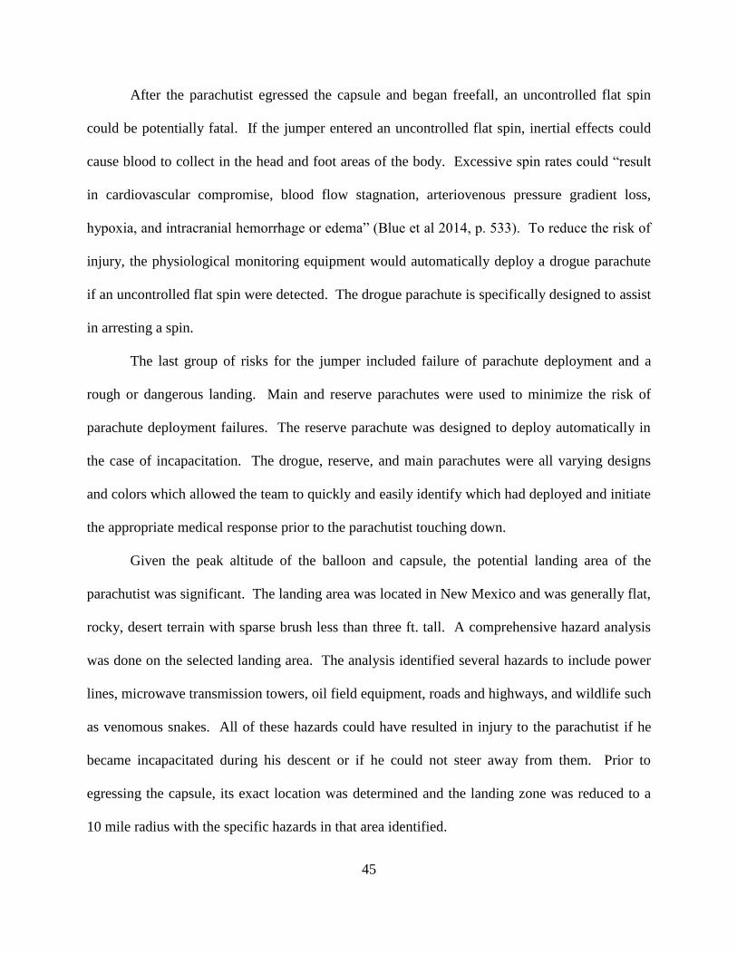
45
After the parachutist egressed the capsule and began freefall, an uncontrolled flat spin
could be potentially fatal. If the jumper entered an uncontrolled flat spin, inertial effects could
cause blood to collect in the head and foot areas of the body. Excessive spin rates could “result
in cardiovascular compromise, blood flow stagnation, arteriovenous pressure gradient loss,
hypoxia, and intracranial hemorrhage or edema” (Blue et al 2014, p. 533). To reduce the risk of
injury, the physiological monitoring equipment would automatically deploy a drogue parachute
if an uncontrolled flat spin were detected. The drogue parachute is specifically designed to assist
in arresting a spin.
The last group of risks for the jumper included failure of parachute deployment and a
rough or dangerous landing. Main and reserve parachutes were used to minimize the risk of
parachute deployment failures. The reserve parachute was designed to deploy automatically in
the case of incapacitation. The drogue, reserve, and main parachutes were all varying designs
and colors which allowed the team to quickly and easily identify which had deployed and initiate
the appropriate medical response prior to the parachutist touching down.
Given the peak altitude of the balloon and capsule, the potential landing area of the
parachutist was significant. The landing area was located in New Mexico and was generally flat,
rocky, desert terrain with sparse brush less than three ft. tall. A comprehensive hazard analysis
was done on the selected landing area. The analysis identified several hazards to include power
lines, microwave transmission towers, oil field equipment, roads and highways, and wildlife such
as venomous snakes. All of these hazards could have resulted in injury to the parachutist if he
became incapacitated during his descent or if he could not steer away from them. Prior to
egressing the capsule, its exact location was determined and the landing zone was reduced to a
10 mile radius with the specific hazards in that area identified.
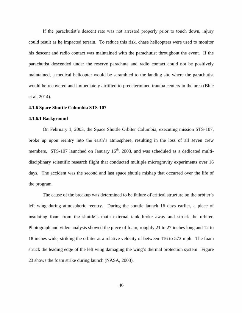
46
If the parachutist’s descent rate was not arrested properly prior to touch down, injury
could result as he impacted terrain. To reduce this risk, chase helicopters were used to monitor
his descent and radio contact was maintained with the parachutist throughout the event. If the
parachutist descended under the reserve parachute and radio contact could not be positively
maintained, a medical helicopter would be scrambled to the landing site where the parachutist
would be recovered and immediately airlifted to predetermined trauma centers in the area (Blue
et al, 2014).
4.1.6 Space Shuttle Columbia STS-107
4.1.6.1 Background
On February 1, 2003, the Space Shuttle Orbiter Columbia, executing mission STS-107,
broke up upon reentry into the earth’s atmosphere, resulting in the loss of all seven crew
members. STS-107 launched on January 16th
, 2003, and was scheduled as a dedicated multi-
disciplinary scientific research flight that conducted multiple microgravity experiments over 16
days. The accident was the second and last space shuttle mishap that occurred over the life of
the program.
The cause of the breakup was determined to be failure of critical structure on the orbiter’s
left wing during atmospheric reentry. During the shuttle launch 16 days earlier, a piece of
insulating foam from the shuttle’s main external tank broke away and struck the orbiter.
Photograph and video analysis showed the piece of foam, roughly 21 to 27 inches long and 12 to
18 inches wide, striking the orbiter at a relative velocity of between 416 to 573 mph. The foam
struck the leading edge of the left wing damaging the wing’s thermal protection system. Figure
23 shows the foam strike during launch (NASA, 2003).
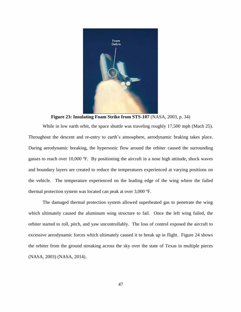
47
Figure 23: Insulating Foam Strike from STS-107 (NASA, 2003, p. 34)
While in low earth orbit, the space shuttle was traveling roughly 17,500 mph (Mach 25).
Throughout the descent and re-entry to earth’s atmosphere, aerodynamic braking takes place.
During aerodynamic breaking, the hypersonic flow around the orbiter caused the surrounding
gasses to reach over 10,000 ºF. By positioning the aircraft in a nose high attitude, shock waves
and boundary layers are created to reduce the temperatures experienced at varying positions on
the vehicle. The temperature experienced on the leading edge of the wing where the failed
thermal protection system was located can peak at over 3,000 ºF.
The damaged thermal protection system allowed superheated gas to penetrate the wing
which ultimately caused the aluminum wing structure to fail. Once the left wing failed, the
orbiter started to roll, pitch, and yaw uncontrollably. The loss of control exposed the aircraft to
excessive aerodynamic forces which ultimately caused it to break up in flight. Figure 24 shows
the orbiter from the ground streaking across the sky over the state of Texas in multiple pieces
(NASA, 2003) (NASA, 2014).

48
Figure 24: STS-107 on Re-Entry (NASA, 2003, p. 41)
For a normal mission, the shuttle’s flight path would have traversed the states of
California, Nevada, Utah, Arizona, New Mexico, Texas, Louisiana, and Florida. For the
accident flight, the shuttle began breaking apart over California and continued to come apart over
Nevada, Utah, Arizona, New Mexico, and Texas. The debris from the shuttle was primarily
recovered in the states of Texas and Louisiana. Figure 25 shows the flight path of the Columbia
orbiter for the accident flight. The yellow dots represent debris shedding events observed from
the ground (NASA, 2014).
Figure 25: STS-107 Trajectory (NASA, 2014, p. 13)
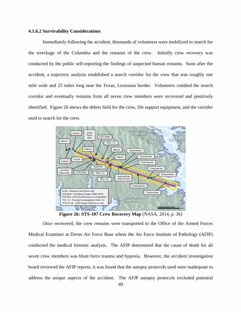
49
4.1.6.2 Survivability Considerations
Immediately following the accident, thousands of volunteers were mobilized to search for
the wreckage of the Columbia and the remains of the crew. Initially crew recovery was
conducted by the public self-reporting the findings of suspected human remains. Soon after the
accident, a trajectory analysis established a search corridor for the crew that was roughly one
mile wide and 25 miles long near the Texas, Louisiana border. Volunteers combed the search
corridor and eventually remains from all seven crew members were recovered and positively
identified. Figure 26 shows the debris field for the crew, life support equipment, and the corridor
used to search for the crew.
Figure 26: STS-107 Crew Recovery Map (NASA, 2014, p. 36)
Once recovered, the crew remains were transported to the Office of the Armed Forces
Medical Examiner at Dover Air Force Base where the Air Force Institute of Pathology (AFIP)
conducted the medical forensic analysis. The AFIP determined that the cause of death for all
seven crew members was blunt force trauma and hypoxia. However, the accident investigation
board reviewed the AFIP reports, it was found that the autopsy protocols used were inadequate to
address the unique aspects of the accident. The AFIP autopsy protocols excluded potential
50
evidence gathering techniques considering the hypersonic, high altitude environment
experienced by the crew. As a result, further analysis was conducted and the cause of death was
modified to blunt force trauma and unprotected exposure to high altitude.
For the survivability analysis, the mishap was organized using two discreet events. The
first event was called the “Catastrophic Event” (CE) which occurred when the orbital fore body
containing the crew module separated from the mid-body. This event occurred between 181,000
and 140,000 ft. and at a velocity of about Mach 15. The second event was the “Crew Module
Catastrophic Event” (CMCE) which included the complete breakup of the crew module. The
injuries experienced by the crew were complex, varied, and were broken down into five
categories:
1. Mechanical injuries experienced during the CE
2. Depressurization injuries experienced after the CE
3. Mechanical injuries experienced after the CE and before the CMCE
4. Thermal injuries experienced after the CMCE
5. Common injuries experienced during the CMCE and impact with the ground (NASA,
2014)
As the orbiter slowly began to lose control due to the left wing failure, the accelerations
experienced by the crew would have been relatively minor. Up to the point of CE, there was
nothing observed which would have been injurious to the crew. Once the fore body separated
from the mid body, all electrical power, oxygen, communication equipment, and crew displays
were lost. Once this occurred, the crew would have realized that they were in an emergency
situation. Crew members sustained injuries consistent with bracing positions indicating that they
were aware of their emergency situation.
51
The crew module was a pressurized vessel in the fore body of the orbiter. As the mid
body and fore body separated, the crew module was free to displace, resulting in damage to the
pressure vessel. Depressurization of the crew module occurred due to a relatively small breach
in the module structure and took place very rapidly at an altitude over 140,000 ft. Analysis of
the crew survival equipment showed that none of the crew had their visors down and sealed on
their helmets and one crew member didn’t have their gloves attached to their suit. As a result,
the pressure suits worn by the crew would not have provided any protection from the low
pressure environment. Ebullism would have occurred immediately and if they survived the
initial trauma due to ebullism, they would have been incapacitated within seconds due to
hypoxia. Gas bubbles indicative of ebullism were found in the crew’s brain and lung tissue,
spinal cord, as well as bone marrow. One crew member is known to have died due to the
ebullism and the resulting pulmonary barotrauma. There was lack of hemorrhage experienced
during subsequent injury mechanisms indicating the cessation of circulatory function.
After depressurization but before the crew module broke up, the accelerations
experienced by the crew gradually increased in severity. Analysis of the crew restraints
indicated that all seven crew members experienced inadequate restraint of the upper torso. Each
crew position utilized a five-point restraint system along with an inertia reel on the shoulder
restraints. Due to the relatively low accelerations initially experienced by the orbiter, the inertia
reels did not lock which would have allowed the shoulder restraints to pay out. This would have
resulted in the upper body of the crew not being properly restrained to the seat back. Once
incapacitated, the crew would have flailed around the crew module improperly restrained. Most
crew members experienced cervical fractures due to unsupported head flail in conjunction with
52
the weight of the helmet. In addition to the fractured vertebra, all but one crew member
experienced hemorrhages in the neck strap muscles.
Most of the crew also experienced soft tissue scalp hematomas, skull fractures, and
several types of brain hemorrhaging due to head flail. The hemorrhaging proved to be critical in
identifying which events occurred prior to death. Once circulatory function stopped,
hemorrhaging would no longer being possible. For all of the crew, the head and neck injuries
were indicative of the upper body flailing unsupported and striking various structures in the crew
module prior to complete break up.
The crew’s next source of injury was due to various thermal exposures after the breach of
the crew module. Once the command module was breached and depressurized, it allowed the
super-heated gases associated with the airflow around the orbiter to penetrate the crew module.
Analysis showed that the crew was exposed to very high thermal energy while still seated in their
seats with their pressure suits on, resulting in very defined skin burns. After some time, the crew
module began to disintegrate, exposing the crew to the full airstream of the vehicle. The wind
blast and aerodynamic environment ripped the pressure suits and other survival gear from the
crew. The nude remains of the crew then passed through hypersonic gas flow and clouds of
molten metal created by the obiter disintegrating and burning up. Trace amounts of aluminum,
titanium, and other metals were found impregnated in the skin of the crew.
After the remains of the crew decelerated from hypersonic to subsonic velocities, they
were then exposed to an altitude in excess of 100,000 ft. Analysis showed injuries consistent
with exposure to near vacuum, highly reactive monatomic oxygen, and freezing ambient
temperatures. The exposure to very low ambient temperatures was associated with the freefall
descent from altitude. Analysis of the lung tissue and blood samples from the crew indicated
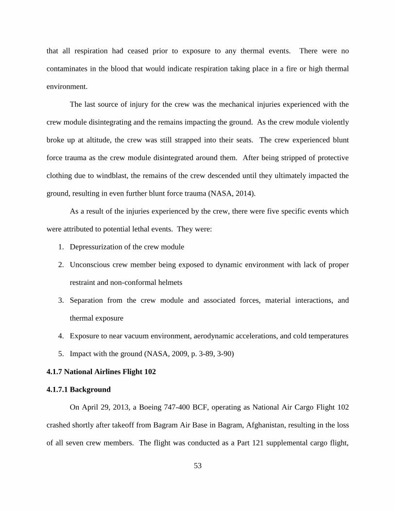
53
that all respiration had ceased prior to exposure to any thermal events. There were no
contaminates in the blood that would indicate respiration taking place in a fire or high thermal
environment.
The last source of injury for the crew was the mechanical injuries experienced with the
crew module disintegrating and the remains impacting the ground. As the crew module violently
broke up at altitude, the crew was still strapped into their seats. The crew experienced blunt
force trauma as the crew module disintegrated around them. After being stripped of protective
clothing due to windblast, the remains of the crew descended until they ultimately impacted the
ground, resulting in even further blunt force trauma (NASA, 2014).
As a result of the injuries experienced by the crew, there were five specific events which
were attributed to potential lethal events. They were:
1. Depressurization of the crew module
2. Unconscious crew member being exposed to dynamic environment with lack of proper
restraint and non-conformal helmets
3. Separation from the crew module and associated forces, material interactions, and
thermal exposure
4. Exposure to near vacuum environment, aerodynamic accelerations, and cold temperatures
5. Impact with the ground (NASA, 2009, p. 3-89, 3-90)
4.1.7 National Airlines Flight 102
4.1.7.1 Background
On April 29, 2013, a Boeing 747-400 BCF, operating as National Air Cargo Flight 102
crashed shortly after takeoff from Bagram Air Base in Bagram, Afghanistan, resulting in the loss
of all seven crew members. The flight was conducted as a Part 121 supplemental cargo flight,
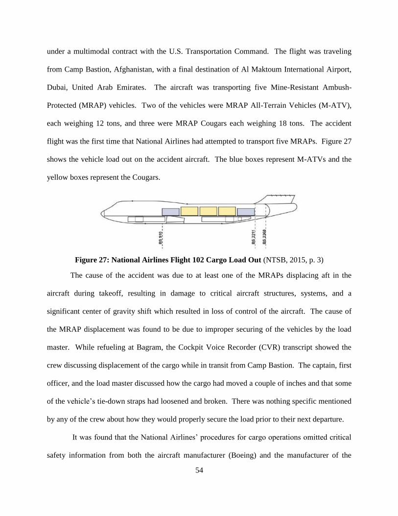
54
under a multimodal contract with the U.S. Transportation Command. The flight was traveling
from Camp Bastion, Afghanistan, with a final destination of Al Maktoum International Airport,
Dubai, United Arab Emirates. The aircraft was transporting five Mine-Resistant Ambush-
Protected (MRAP) vehicles. Two of the vehicles were MRAP All-Terrain Vehicles (M-ATV),
each weighing 12 tons, and three were MRAP Cougars each weighing 18 tons. The accident
flight was the first time that National Airlines had attempted to transport five MRAPs. Figure 27
shows the vehicle load out on the accident aircraft. The blue boxes represent M-ATVs and the
yellow boxes represent the Cougars.
Figure 27: National Airlines Flight 102 Cargo Load Out (NTSB, 2015, p. 3)
The cause of the accident was due to at least one of the MRAPs displacing aft in the
aircraft during takeoff, resulting in damage to critical aircraft structures, systems, and a
significant center of gravity shift which resulted in loss of control of the aircraft. The cause of
the MRAP displacement was found to be due to improper securing of the vehicles by the load
master. While refueling at Bagram, the Cockpit Voice Recorder (CVR) transcript showed the
crew discussing displacement of the cargo while in transit from Camp Bastion. The captain, first
officer, and the load master discussed how the cargo had moved a couple of inches and that some
of the vehicle’s tie-down straps had loosened and broken. There was nothing specific mentioned
by any of the crew about how they would properly secure the load prior to their next departure.
It was found that the National Airlines’ procedures for cargo operations omitted critical
safety information from both the aircraft manufacturer (Boeing) and the manufacturer of the
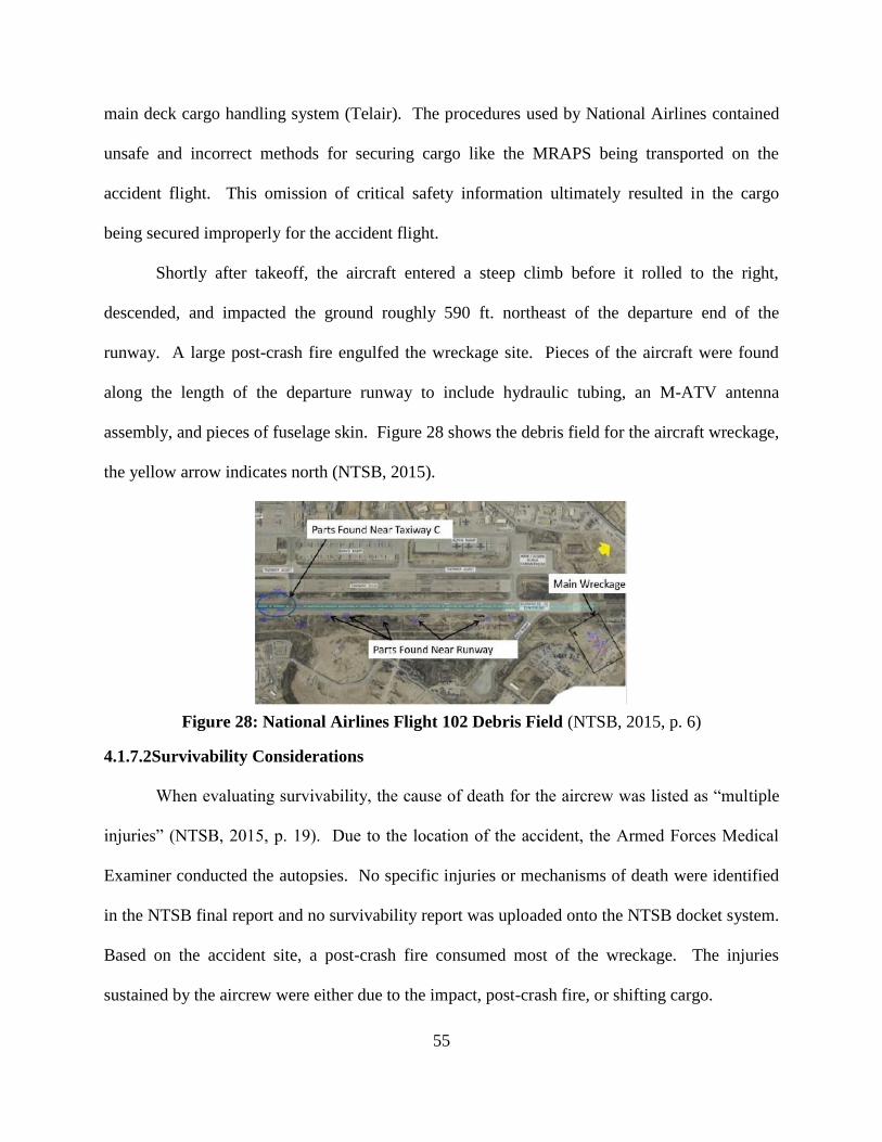
55
main deck cargo handling system (Telair). The procedures used by National Airlines contained
unsafe and incorrect methods for securing cargo like the MRAPS being transported on the
accident flight. This omission of critical safety information ultimately resulted in the cargo
being secured improperly for the accident flight.
Shortly after takeoff, the aircraft entered a steep climb before it rolled to the right,
descended, and impacted the ground roughly 590 ft. northeast of the departure end of the
runway. A large post-crash fire engulfed the wreckage site. Pieces of the aircraft were found
along the length of the departure runway to include hydraulic tubing, an M-ATV antenna
assembly, and pieces of fuselage skin. Figure 28 shows the debris field for the aircraft wreckage,
the yellow arrow indicates north (NTSB, 2015).
Figure 28: National Airlines Flight 102 Debris Field (NTSB, 2015, p. 6)
4.1.7.2Survivability Considerations
When evaluating survivability, the cause of death for the aircrew was listed as “multiple
injuries” (NTSB, 2015, p. 19). Due to the location of the accident, the Armed Forces Medical
Examiner conducted the autopsies. No specific injuries or mechanisms of death were identified
in the NTSB final report and no survivability report was uploaded onto the NTSB docket system.
Based on the accident site, a post-crash fire consumed most of the wreckage. The injuries
sustained by the aircrew were either due to the impact, post-crash fire, or shifting cargo.
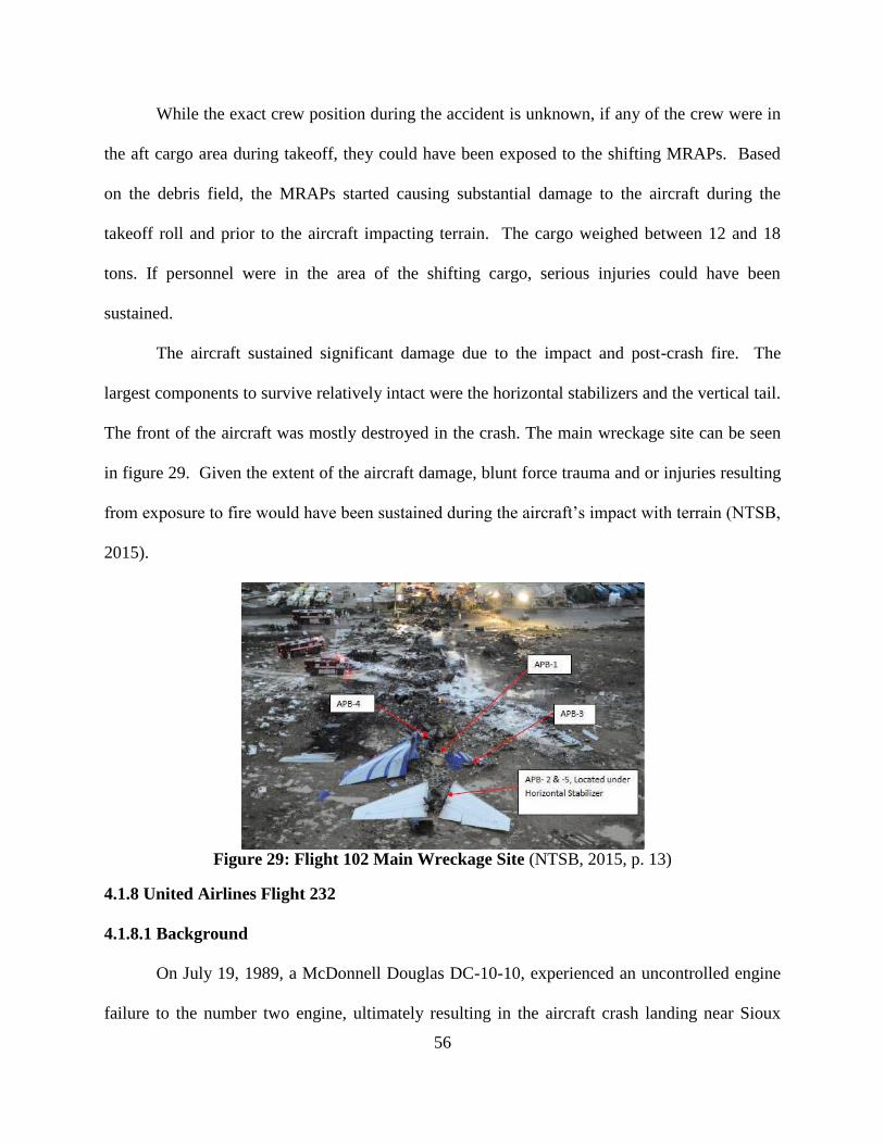
56
While the exact crew position during the accident is unknown, if any of the crew were in
the aft cargo area during takeoff, they could have been exposed to the shifting MRAPs. Based
on the debris field, the MRAPs started causing substantial damage to the aircraft during the
takeoff roll and prior to the aircraft impacting terrain. The cargo weighed between 12 and 18
tons. If personnel were in the area of the shifting cargo, serious injuries could have been
sustained.
The aircraft sustained significant damage due to the impact and post-crash fire. The
largest components to survive relatively intact were the horizontal stabilizers and the vertical tail.
The front of the aircraft was mostly destroyed in the crash. The main wreckage site can be seen
in figure 29. Given the extent of the aircraft damage, blunt force trauma and or injuries resulting
from exposure to fire would have been sustained during the aircraft’s impact with terrain (NTSB,
2015).
Figure 29: Flight 102 Main Wreckage Site (NTSB, 2015, p. 13)
4.1.8 United Airlines Flight 232
4.1.8.1 Background
On July 19, 1989, a McDonnell Douglas DC-10-10, experienced an uncontrolled engine
failure to the number two engine, ultimately resulting in the aircraft crash landing near Sioux
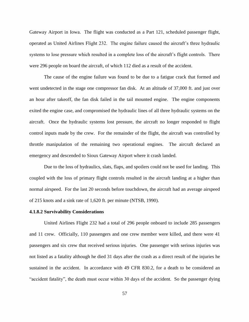
57
Gateway Airport in Iowa. The flight was conducted as a Part 121, scheduled passenger flight,
operated as United Airlines Flight 232. The engine failure caused the aircraft’s three hydraulic
systems to lose pressure which resulted in a complete loss of the aircraft’s flight controls. There
were 296 people on board the aircraft, of which 112 died as a result of the accident.
The cause of the engine failure was found to be due to a fatigue crack that formed and
went undetected in the stage one compressor fan disk. At an altitude of 37,000 ft. and just over
an hour after takeoff, the fan disk failed in the tail mounted engine. The engine components
exited the engine case, and compromised the hydraulic lines of all three hydraulic systems on the
aircraft. Once the hydraulic systems lost pressure, the aircraft no longer responded to flight
control inputs made by the crew. For the remainder of the flight, the aircraft was controlled by
throttle manipulation of the remaining two operational engines. The aircraft declared an
emergency and descended to Sioux Gateway Airport where it crash landed.
Due to the loss of hydraulics, slats, flaps, and spoilers could not be used for landing. This
coupled with the loss of primary flight controls resulted in the aircraft landing at a higher than
normal airspeed. For the last 20 seconds before touchdown, the aircraft had an average airspeed
of 215 knots and a sink rate of 1,620 ft. per minute (NTSB, 1990).
4.1.8.2 Survivability Considerations
United Airlines Flight 232 had a total of 296 people onboard to include 285 passengers
and 11 crew. Officially, 110 passengers and one crew member were killed, and there were 41
passengers and six crew that received serious injuries. One passenger with serious injuries was
not listed as a fatality although he died 31 days after the crash as a direct result of the injuries he
sustained in the accident. In accordance with 49 CFR 830.2, for a death to be considered an
“accident fatality”, the death must occur within 30 days of the accident. So the passenger dying
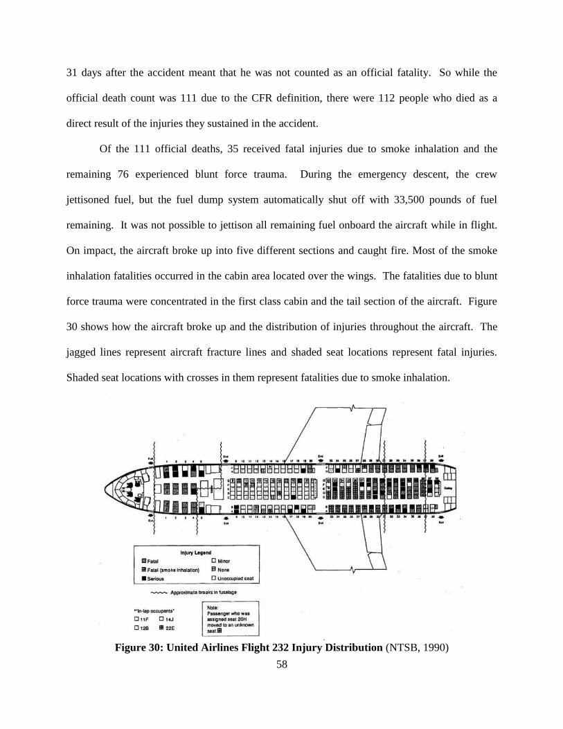
58
31 days after the accident meant that he was not counted as an official fatality. So while the
official death count was 111 due to the CFR definition, there were 112 people who died as a
direct result of the injuries they sustained in the accident.
Of the 111 official deaths, 35 received fatal injuries due to smoke inhalation and the
remaining 76 experienced blunt force trauma. During the emergency descent, the crew
jettisoned fuel, but the fuel dump system automatically shut off with 33,500 pounds of fuel
remaining. It was not possible to jettison all remaining fuel onboard the aircraft while in flight.
On impact, the aircraft broke up into five different sections and caught fire. Most of the smoke
inhalation fatalities occurred in the cabin area located over the wings. The fatalities due to blunt
force trauma were concentrated in the first class cabin and the tail section of the aircraft. Figure
30 shows how the aircraft broke up and the distribution of injuries throughout the aircraft. The
jagged lines represent aircraft fracture lines and shaded seat locations represent fatal injuries.
Shaded seat locations with crosses in them represent fatalities due to smoke inhalation.
Figure 30: United Airlines Flight 232 Injury Distribution (NTSB, 1990)

59
Flight 232 had a total of four lap-held infants on the aircraft. The infants were held by
passengers sitting in seats 11F, 12B, 14J, and 22E. All of the lap-held infants were seated in the
section of the aircraft that separated and remained attached to the wings. When preparing for
landing, flight attendants instructed the parents to place their children on the floor and to hold
them once they assumed the emergency landing braced position. The parents seated in 11F and
22E were unable to hold onto their child during the crash landing and could not find their
children post-crash. The parent in seat 12B noted that their child “flew up into the air upon
impact” (NTSB, 1990, p. 40), but they were ultimately able to grab and hold them. Of the four
infants, one died due to smoke inhalation (NTSB, 1990).
While none of the lap-held infants died as a result of blunt force trauma, the unrestrained
infants were exposed to significantly higher risk of blunt force trauma. They also exposed
passengers seated in their immediate vicinity to projectiles throughout the crash event. As the
aircraft crash landed, the dynamics of the event exposed the occupants to relatively high
accelerations and forces. As the unrestrained infants moved freely about the cabin during the
crash, any major collisions with other passengers or aircraft structure could expose both the child
and hit passenger to blunt force trauma. This blunt force trauma could result in serious or fatal
injuries.
4.2 Special Considerations - Escape Systems
To prevent the risk of injuries associated with a crash, some aircraft may be equipped
with escape systems to be used in the case of an emergency. Currently CREEP doesn’t consider
escape systems at all. Escape systems are designed so that the crew can egress the stricken
aircraft and separate before impact with the ground. Escape systems may include things like
parachutes, ejection seats, or escape modules. Each type of escape system is unique and present
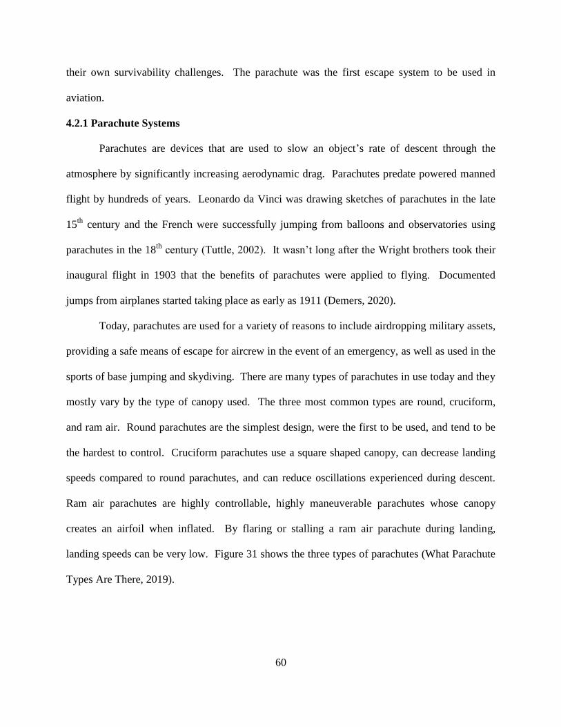
60
their own survivability challenges. The parachute was the first escape system to be used in
aviation.
4.2.1 Parachute Systems
Parachutes are devices that are used to slow an object’s rate of descent through the
atmosphere by significantly increasing aerodynamic drag. Parachutes predate powered manned
flight by hundreds of years. Leonardo da Vinci was drawing sketches of parachutes in the late
15th
century and the French were successfully jumping from balloons and observatories using
parachutes in the 18th
century (Tuttle, 2002). It wasn’t long after the Wright brothers took their
inaugural flight in 1903 that the benefits of parachutes were applied to flying. Documented
jumps from airplanes started taking place as early as 1911 (Demers, 2020).
Today, parachutes are used for a variety of reasons to include airdropping military assets,
providing a safe means of escape for aircrew in the event of an emergency, as well as used in the
sports of base jumping and skydiving. There are many types of parachutes in use today and they
mostly vary by the type of canopy used. The three most common types are round, cruciform,
and ram air. Round parachutes are the simplest design, were the first to be used, and tend to be
the hardest to control. Cruciform parachutes use a square shaped canopy, can decrease landing
speeds compared to round parachutes, and can reduce oscillations experienced during descent.
Ram air parachutes are highly controllable, highly maneuverable parachutes whose canopy
creates an airfoil when inflated. By flaring or stalling a ram air parachute during landing,
landing speeds can be very low. Figure 31 shows the three types of parachutes (What Parachute
Types Are There, 2019).
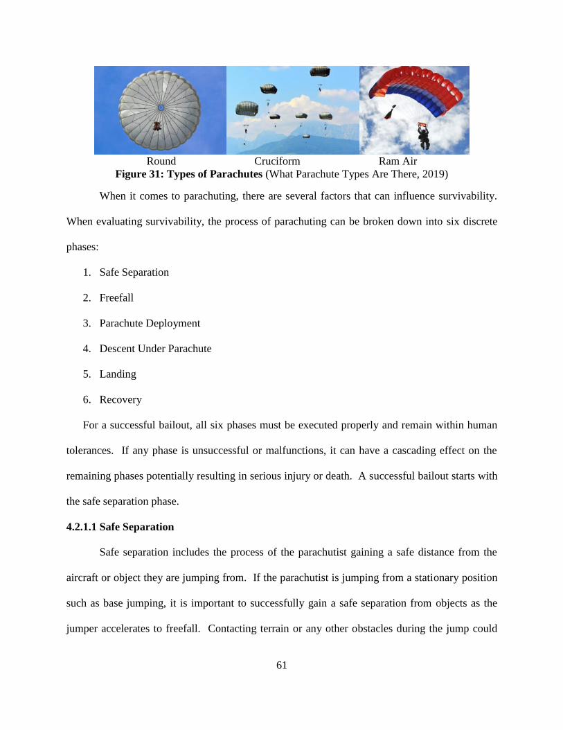
61
Round Cruciform Ram Air
Figure 31: Types of Parachutes (What Parachute Types Are There, 2019)
When it comes to parachuting, there are several factors that can influence survivability.
When evaluating survivability, the process of parachuting can be broken down into six discrete
phases:
1. Safe Separation
2. Freefall
3. Parachute Deployment
4. Descent Under Parachute
5. Landing
6. Recovery
For a successful bailout, all six phases must be executed properly and remain within human
tolerances. If any phase is unsuccessful or malfunctions, it can have a cascading effect on the
remaining phases potentially resulting in serious injury or death. A successful bailout starts with
the safe separation phase.
4.2.1.1 Safe Separation
Safe separation includes the process of the parachutist gaining a safe distance from the
aircraft or object they are jumping from. If the parachutist is jumping from a stationary position
such as base jumping, it is important to successfully gain a safe separation from objects as the
jumper accelerates to freefall. Contacting terrain or any other obstacles during the jump could
62
result in blunt force trauma injuries. In the case of egressing aircraft, it is important for the
parachutists to successfully get to the egress door and clear the aircraft.
Egressing an aircraft may be done for the sport of skydiving or during an emergency.
When egressing during an emergency, the aircraft may not be under control or in steady level
flight. The task of simply getting from the occupant seat to the egress door may present hazards
and sources of injuries. Once at the egress door, it is important for the parachutist to get
successful separation from the aircraft. If the jumper strikes any portion of the aircraft while
attempting to gain separation, blunt force trauma injuries may be experienced.
Once separated, the parachutist will either accelerate or decelerate until they reach
freefall or terminal velocity. Terminal velocity is defined as the speed at which an object falls
where the force of gravity is exactly equal to the force of aerodynamic drag. At terminal velocity
an object achieves equilibrium and stops accelerating. Terminal velocity is considered freefall
and varies based on atmospheric conditions and an individual’s size and body position relative to
the free stream airflow. The terminal velocity of a typical parachutist can vary from between
125 to 300 mph (Westman, 2005). During the Red Bull Stratos project, Felix Baumgartner
exceeded 820 mph during his freefall from over 120,000 ft. in altitude.
If a jumper is egressing an aircraft, the parachutist may accelerate or decelerate when
hitting the free stream velocity depending on the airspeed of the aircraft. If the aircraft is flying
faster than the jumper’s terminal velocity, they will decelerate. Conversely, if the aircraft is
flying slower than the jumper’s terminal velocity, they will accelerate. If egressing from a high
performance aircraft, flail injuries may be experienced if the jumper egresses the aircraft at too
high an airspeed. When initially hitting the free stream airflow, the aerodynamic forces also
63
called the “wind blast”, may be high enough to cause flail injuries to the jumper’s limbs, head,
and neck.
4.2.1.2 Freefall
Once the parachutist reaches terminal velocity, they are considered to be in freefall. The
hazards that are present during freefall include instability, midair collisions, the immediate
surroundings, and the environment. The risk of instability and spins were addressed in section
4.1.5, the Red Bull Stratos project. During freefall there is a potential that the parachutist could
contact other jumpers, birds, aircraft debris, or any other objects in the airspace. Due to the high
speeds involved in freefall, midair collisions could result in blunt force trauma injuries. Another
source of injury during freefall is the jumper’s immediate surroundings and environment.
Depending on the altitude where egress is initiated, the high altitude environment may
present survivability challenges. If jumping from altitudes above 10,000 ft., supplemental
oxygen may be required based on exposure times. The lack of supplemental oxygen can cause
hypoxia which can reduce awareness, render someone unconscious, and even result in death.
Low temperatures are also a consideration when considering the environment. Low ambient
temperatures coupled with the high descent rates associated with freefall, increase the risk of
cold weather injuries such as frostbite and hypothermia. Frostbite or reduced dexterity may
prevent the parachutist from successfully operating the parachute. Unsuccessful parachute
deployment or failure to operate the parachute properly may result in ground impact at a high
rate of speed.
Another consideration is adverse weather. Weather specific hazards to parachutists
during freefall include factors such as lightning, hail, drowning, and freezing rain. Adverse
weather like thunderstorms pose a substantial risk to a parachutist. As the jumper falls, they may

64
become statically charged which exposes them to a higher risk of lightning strikes. Some
thunderstorms can also produce significant hail stones. Striking those hail stones may result in
blunt force trauma injuries. In addition, if the concentration of condensed water is high enough
within a cloud, it may be difficult for the parachutist to breathe. Due to the violent updrafts
associated with some types of clouds, freefalling through a cumulonimbus cloud may expose the
jumper to the risk of drowning. While hypothermia and frostbite have already been addressed,
freezing rain during freefall has the potential to accelerate the onset of those conditions (Pretor-
Pinney, 2007).
4.2.1.3 Parachute Deployment
Parachute deployment is one of the most critical phases of parachuting. Failure of the
parachute to properly deploy and achieve full canopy inflation can lead to excessive descent rates
resulting in serious injuries during landing. Parachute deployment methods can vary based on
application. They can be deployed automatically though systems such as static lines or
automatic activation systems. They can also be deployed manually by the parachutist typically
by pulling a handle or rip cord of some sort. There are many causes of failure of a parachute to
deploy properly such as failure of the deployment system, jumper instability or improper
positioning, excessive speed, incorrect packing procedure, or multiple deployments. During the
deployment process, improperly fit equipment also poses a significant risk of injury.
Regardless of the deployment method, it is important that the system activate properly
and within the design limits of the parachute. If a static line were to fail, if a parachutist fails to
pull their activation handle, or if an automatic deployment system fails to function, the parachute
may not deploy at all which could cause the jumper to impact terrain at terminal velocity. If
deployment is not initiated at an appropriate altitude, the parachute canopy may not have enough
65
time to inflate and properly arrest the rate of descent before landing. Between the years of 1964
and 2003, 11 skydiving fatalities in Sweden were associated to a complete lack of parachute
activation or initiating parachute activation at a low altitude (Westman, et. al, 2005).
Prior to parachute deployment, it is critical that the jumper be in a stable, proper position
and that the parachute’s deployment speed is appropriate for the specific parachute. Improper
and unstable body position resulted in three fatalities in the U.S. Army in the five year period
from 2010 through 2015 (Johnson, et. al. 2019). Instability such as an uncontrolled spin or
improper body position can cause the parachute to malfunction during deployment or it can
become entangled around the head and neck, which can result in cervical spine injuries or
suffocation.
Excessive speed at parachute deployment can result in high opening shock loads,
parachute damage and failure, or parachute malfunction. If a parachute is deployed outside of its
designed operating range, the parachute inflation can result in excessive loads being applied to
the parachutist. If opening shock loads are too high, the parachutist can experience compressive
injuries to the spine and flail injuries to the head and neck. Opening shock loads may also cause
failure to the canopy or parachute lines, which may produce an unstable parachute or
malfunction which can result in higher descent speeds at landing.
A parachute that is incorrectly packed may experience deployment malfunctions. As the
parachute deploys, the lines spread and the canopy inflates. If not packed properly, the lines can
tangle or interfere with the canopy, preventing proper inflation resulting in higher decent speeds.
The last source of parachute deployment malfunction is when multiple deployments occur.
Most man-mounted parachute systems only use one parachute for descent. To reduce the
risk of total system failure, a redundant or reserve parachute is commonly used. This allows the
66
parachutist to jettison the main parachute in the case of malfunction or failure. However, when
both the main and reserve parachutes are deployed simultaneously, they may become entangled.
Entangled parachutes may prevent the proper inflation of both parachute canopies or make the
parachutes impossible to control. One fatality was attributed to multiple parachute deployments
in Swedish skydiving between 1964 and 2003 (Westman, et. al, 2005).
When using a parachute, it is critical that the parachute harness be properly sized and
fitted to the parachutist. An improperly sized or very loose fitting harness could result in the
harness failing to secure the parachutist to the parachute or also result in injuries during
deployment. During parachute deployment, the opening shock loads could cause the parachutist
to completely fall from an improperly fit or loose harness. An improperly worn harness could
also result in the transfer of opening shock loads to incorrect parts of the body such as the head
and neck causing serious or fatal injuries (M. Mackenzie, personal communication, August 19,
2020).
4.2.1.4 Descent Under Parachute
Once the parachute has successfully deployed and the canopy is fully inflated, the
parachutist’s descent rate will be arrested from their freefall speed. The hazards associated with
descending under parachute are very similar to the hazards of freefall, including midair collisions
and the environment.
Much like in freefall, midair collisions expose the parachutist to the potential of blunt
force trauma injuries. But while descending under parachute, midair collisions can also result in
both parachute malfunction and entanglement. Similar to multiple deployments, entanglement
due to a midair collision reduces the effectiveness of both the parachutes involved and a
successful recovery can be difficult to achieve. Parachute entanglement resulted in two fatalities

67
in the U.S. Army between 2010 and 2015 (Johnson, et. al. 2019). In addition to midair
collisions, the jumper’s local surroundings and environment exposes the jumper to risk of injury.
Much like during freefall, the local environment and adverse weather can pose a serious
threat. While the threats of hypoxia, hypothermia, frostbite, lightning strikes, drowning, and
blunt force trauma also exist under canopy, something unique to the environment during descent
is the parachute interacting with the adverse weather. In 1959, after ejecting at 47,000 ft. over a
severe thunderstorm, Lt. Col. William Rankin took over 40 minutes to descend. During his 40
minute descent he was exposed to freezing temperatures, lightning, threat of drowning, hail, and
an extremely turbulent environment. If parachuting in storms, severe updrafts can interact with
the parachute and pull the parachutist skyward. Even with parachute deployment at altitudes
with low risk of hypoxia, storms can grab the parachutist and send them to unsafe altitudes.
Once in the storm, the turbulent environment may also cause damage to the parachute itself.
Any damage to the canopy or parachute lines may reduce the effectiveness of the parachute and
may result in excessive landing speeds (Pretor-Pinney, 2007).
4.2.1.5 Landing
As the parachutist descends, they will lose altitude until they eventually impact terrain.
The area where a parachutist lands is referred to as the “landing zone”. If parachuting operations
are planned, landing zone hazards can be identified ahead of time to minimize risks. However, if
parachuting is done as a result of an emergency egress, mitigating the risks associated with a
landing zone may not be possible. Hazards that can impact survivability during landing include
terrain features, landing zone hazards, and excessive descent rates.
The landing zone should ideally be flat, unobstructed, soft terrain that allows the
parachutist to land and recover quickly. Adverse terrain such as mountainous, rocky, or forested

68
areas can result in the parachutist experiencing blunt force trauma or impalement injuries during
landing. Man-made obstructions in the landing zone can also present hazards to parachutists.
Some of the landing zone hazards identified during the Red Bull Stratos project included
power lines, microwave transmission towers, oil field equipment, and roads. Other landing zone
hazards include fire, and aircraft wreckage. If parachuting is a result of emergency egress, it is
possible for the ditched aircraft to crash in the landing zone, resulting in a post-crash fire. If
possible, it is important for the parachutist to steer away from the aircraft wreckage or any other
hazards in the landing zone. In addition to landing zone hazards, excessive landing speeds can
result in serious injuries.
It is important to note that parachutes only reduce the descent rate of a parachutist. The
new T-11 cruciform parachute used by the U.S. military has a descent rate of about 13 mph
(Johnson, et. al., 2019). Depending on the total weight of the jumper, atmospheric conditions,
and the design of the parachute, descent rates can vary significantly. An important consideration
is that the descent rate only represents the vertical speed of the parachutists. Factors such as
winds and control inputs can impact the longitudinal and lateral speeds. For round and cruciform
parachutes, excessive winds in the landing zone can significantly increase landing speeds. Due
to the flying nature of ram air parachutes, control inputs can create very high landing speeds for
the parachutist. As landing speeds increase, the risk of experiencing blunt force trauma during
landing also increases.
To reduce the risk of injury at any landing speed, the Parachute Landing Fall (PLF) may
be used when the landing speed is primarily in the vertical direction. The PLF is intended to
reduce the risk of injury to the legs and back by spreading out the landing forces over the entire
body. Careful consideration should be made to protect the head from strikes during PLF. The
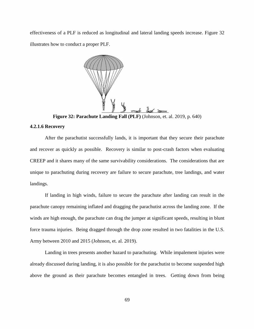
69
effectiveness of a PLF is reduced as longitudinal and lateral landing speeds increase. Figure 32
illustrates how to conduct a proper PLF.
Figure 32: Parachute Landing Fall (PLF) (Johnson, et. al. 2019, p. 640)
4.2.1.6 Recovery
After the parachutist successfully lands, it is important that they secure their parachute
and recover as quickly as possible. Recovery is similar to post-crash factors when evaluating
CREEP and it shares many of the same survivability considerations. The considerations that are
unique to parachuting during recovery are failure to secure parachute, tree landings, and water
landings.
If landing in high winds, failure to secure the parachute after landing can result in the
parachute canopy remaining inflated and dragging the parachutist across the landing zone. If the
winds are high enough, the parachute can drag the jumper at significant speeds, resulting in blunt
force trauma injuries. Being dragged through the drop zone resulted in two fatalities in the U.S.
Army between 2010 and 2015 (Johnson, et. al. 2019).
Landing in trees presents another hazard to parachuting. While impalement injuries were
already discussed during landing, it is also possible for the parachutist to become suspended high
above the ground as their parachute becomes entangled in trees. Getting down from being
70
suspended in trees may not be easily accomplished. A high fall presents a significant source of
injury for a parachutist.
Something also unique to parachuting is landing in water. When parachuting over water,
it is critically important for the parachutist to separate and distance themselves from their
parachute immediately after landing. While emergency egress and water survival is covered
under CREEP, parachutes provide a unique drowning hazard. Even with the use of supplemental
flotation systems, parachutes can adversely interact with the water and cause drowning. By
interacting with water currents, the parachute canopy can act as a sea anchor and drag the
parachutist under the surface. In addition to the sea anchor effect, the parachute lines may also
become entangled around the parachutists preventing them from swimming and remaining afloat.
Drowning resulted in four fatalities in Swedish skydivers between the years of 1964 and 1973
(Westman, et. al, 2005).
4.2.2 Ejection Seat Systems
Up to and including much of World War II, the primary means of escape from an aircraft
was by bailing out with a parachute. However, as aircraft performance increased, it became clear
that bailing out was becoming less and less effective. As air speeds increased, the ability for
crew to react fast enough, overcome aerodynamic forces, and gain successful separation from the
aircraft decreased (Copp, et. al, 2015).
A high percentage of aircraft accidents occur during takeoff and landing. Due to the
higher landing and takeoff speeds of high performance aircraft, traditional energy absorbing and
crashworthy structures became less effective at protecting aircrew. While in the air, higher
aerodynamic forces make it difficult to egress and clear aircraft structures such as horizontal and
vertical control surfaces during bailout. The need for mechanical assistance during emergency
71
egress was clear and the ejection seat was born (G. Paskoff, personal communication, July 2,
2019).
The first ejection seats were mostly manual systems and used compressed air to assist the
occupant in clearing the aircraft. After gaining aircraft separation, the occupant was responsible
for manually separating from the seat and deploying the parachute. The Germans pioneered the
use of ejection seats during World War II where they had over 60 successful escapes using
ejections seats (Newman, 2017).
The first ejection from an aircraft using explosives was done in July 1946 by using a
Martin-Baker system. A modified Gloster Meteor F-3 was used to conduct an ejection test
where Sir Bernard Lynch was ejected using a MB Mk-1 seat at an attitude of 8,000 ft. and at an
airspeed of about 300 mph. It took Lynch over 30 seconds to successfully gain seat separation
and successfully deploy his parachute. Over the years, ejection seats have changed significantly.
To overcome the potential issue of clearing the very large tail on the F-104, ejection seats were
designed to eject the pilot downward. However due to killing several pilots during ejections in
close proximity to the ground, those systems are rarely in use today (Copp, et al., 2015).
Today, modern ejection seats have become more automated and can protect aircrew over
a much broader range of conditions. The most advanced ejection seats can autonomously
execute the entire ejection sequence including initiation. In 1946, it took over 30 seconds to get
parachute deployment once clear of the aircraft. Today, that process can take less than 0.3
seconds (Copp, et al., 2015).
While there are many different models of ejection seats specifically tailored to individual
aircraft types, they all share similar characteristics. There are nine discreet phases of a
successful ejection using a modern ejection seat:
72
1. Ejection Initiation
2. Aircrew Positioning
3. Canopy/Hatch Jettison/Fracturing
4. Aircraft Separation
5. In-Seat Descent and Stabilization
6. Parachute Deployment
7. Occupant-Seat Separation
8. Parachute Descent
9. Landing
10. Recovery (M. Mackenzie, personal communication, August 19, 2020) (J. Santiago,
personal communication, August 18, 2020)
For a successful ejection to take place, all ten phases must be executed and function
properly. If any phase is unsuccessful or malfunctions, it can have a cascading effect on the
remaining phases potentially resulting in serious injury or death. A successful ejection starts
with the ejection initiation phase.
4.2.2.1 Ejection Initiation
The first phase of an ejection starts with the activation and initiation of the ejection seat
system. For a majority of ejection seats, this is accomplished by the aircrew pulling on a handle
attached to their seat typically located between their legs. Prior to ejection initiation, it is critical
that ejection initiation takes place within what is referred to as a “safe escape envelope”.
The safe escape envelope will vary between specific systems and aircraft. It is a
combination of multiple factors such as ejection seat performance, aircraft airspeed, attitude,
altitude, and sink rate. Once ejection is initiated, egress and parachute deployment are not
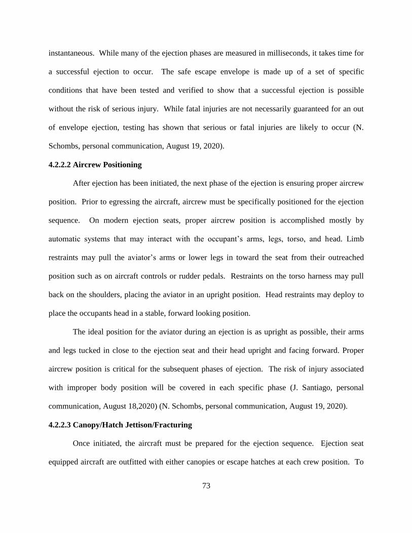
73
instantaneous. While many of the ejection phases are measured in milliseconds, it takes time for
a successful ejection to occur. The safe escape envelope is made up of a set of specific
conditions that have been tested and verified to show that a successful ejection is possible
without the risk of serious injury. While fatal injuries are not necessarily guaranteed for an out
of envelope ejection, testing has shown that serious or fatal injuries are likely to occur (N.
Schombs, personal communication, August 19, 2020).
4.2.2.2 Aircrew Positioning
After ejection has been initiated, the next phase of the ejection is ensuring proper aircrew
position. Prior to egressing the aircraft, aircrew must be specifically positioned for the ejection
sequence. On modern ejection seats, proper aircrew position is accomplished mostly by
automatic systems that may interact with the occupant’s arms, legs, torso, and head. Limb
restraints may pull the aviator’s arms or lower legs in toward the seat from their outreached
position such as on aircraft controls or rudder pedals. Restraints on the torso harness may pull
back on the shoulders, placing the aviator in an upright position. Head restraints may deploy to
place the occupants head in a stable, forward looking position.
The ideal position for the aviator during an ejection is as upright as possible, their arms
and legs tucked in close to the ejection seat and their head upright and facing forward. Proper
aircrew position is critical for the subsequent phases of ejection. The risk of injury associated
with improper body position will be covered in each specific phase (J. Santiago, personal
communication, August 18,2020) (N. Schombs, personal communication, August 19, 2020).
4.2.2.3 Canopy/Hatch Jettison/Fracturing
Once initiated, the aircraft must be prepared for the ejection sequence. Ejection seat
equipped aircraft are outfitted with either canopies or escape hatches at each crew position. To
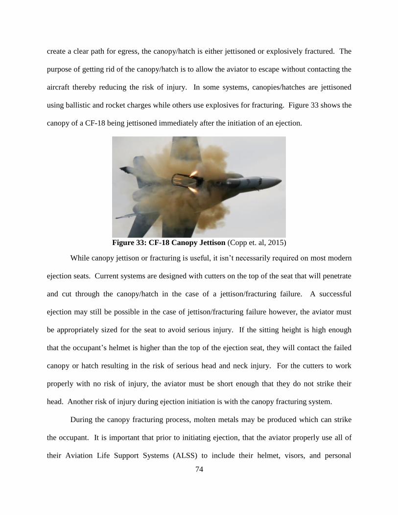
74
create a clear path for egress, the canopy/hatch is either jettisoned or explosively fractured. The
purpose of getting rid of the canopy/hatch is to allow the aviator to escape without contacting the
aircraft thereby reducing the risk of injury. In some systems, canopies/hatches are jettisoned
using ballistic and rocket charges while others use explosives for fracturing. Figure 33 shows the
canopy of a CF-18 being jettisoned immediately after the initiation of an ejection.
Figure 33: CF-18 Canopy Jettison (Copp et. al, 2015)
While canopy jettison or fracturing is useful, it isn’t necessarily required on most modern
ejection seats. Current systems are designed with cutters on the top of the seat that will penetrate
and cut through the canopy/hatch in the case of a jettison/fracturing failure. A successful
ejection may still be possible in the case of jettison/fracturing failure however, the aviator must
be appropriately sized for the seat to avoid serious injury. If the sitting height is high enough
that the occupant’s helmet is higher than the top of the ejection seat, they will contact the failed
canopy or hatch resulting in the risk of serious head and neck injury. For the cutters to work
properly with no risk of injury, the aviator must be short enough that they do not strike their
head. Another risk of injury during ejection initiation is with the canopy fracturing system.
During the canopy fracturing process, molten metals may be produced which can strike
the occupant. It is important that prior to initiating ejection, that the aviator properly use all of
their Aviation Life Support Systems (ALSS) to include their helmet, visors, and personal
75
protective clothing. Failure of the occupant to properly wear their helmet with a lowered visor
could result in molten metals becoming impregnated in their face and eyes. While not
immediately a life threatening injury, the injury could result in loss of vision which could
compromise post-ejection survival considerations such as steering the parachute away from
hazards, or the effective use of a life raft or survival radio (M. Mackenzie, personal
communication, August 19, 2020).
Another important consideration for ejection seat equipped aircraft is rapid
decompression. While the aircraft may be pressurized to accommodate the altitude of the
aircraft, as soon as ejection is initiated and the canopy/hatch is compromised rapid
decompression will occur. Unless a pressure suit is worn by the crew, the risk of decompressive
injuries increases if ejection is initiated in a high altitude low pressure environment (Pretor-
Pinney, 2007).
4.2.2.4 Aircraft Separation
Occupant separation from the aircraft starts once the aircrew is placed in the proper
position and the aircraft has been prepared for egress. In modern ejection seats, this is
accomplished by both a catapult mounted to the aircraft and an under-seat rocket motor. During
this phase, the occupant may be exposed to significant forces in the vertical, longitudinal, and
lateral directions. Vertical forces are experienced due to the catapult and under-seat rocket
motor accelerating the occupant up and out of the aircraft. Longitudinal and lateral forces may
be experienced due to the occupant hitting the aircraft’s wind blast.
When dealing with vertical accelerations, it is critical that the occupant be in an upright
position as an upward spine position provides the optimal biomechanical tolerance to injury.
Accelerations in the vertical direction during the aircraft separation phase may be as high as 16
76
Gs (Newman, 2017). If the aviator is out of position, compressive injuries to the spine such as
ruptured vertebral disks or compressive fractures may be experienced. Also, if the crew is out of
position they can strike the aircraft as they are catapulted resulting in significant injuries. In
addition to position, the occupant’s anthropometric measurements may impact survivability.
Some ejection seats may have only one mode of ejection when accounting for weight.
The catapult and under-seat rocket motor apply a fixed load regardless of occupant size. If the
aviator is too light, the accelerations experienced can exceed human tolerances and cause
compressive injuries to the spine. If the aviator is too heavy, the system may not have enough
energy to guarantee successful aircraft separation and they may strike the aircraft or not gain
enough ground clearance. If an occupant’s height and weight are not sized correctly for the seat,
adverse interactions between the seat and torso harness may cause injury (G. Paskoff, personal
communication, July 2, 2019). In addition to vertical accelerations, the occupant may be
exposed to significant longitudinal and lateral accelerations.
In high performance aircraft high airspeeds are common. The occupants of the ejection
seat are instantaneously exposed to the free stream airflow as they gain aircraft separation. Like
during bailout procedures, this airflow is often called the wind blast. The aircraft wind blast can
expose the occupant to significant aerodynamic forces. Depending on aircraft attitude at the time
of ejection, the occupant may experience significant longitudinal and lateral forces. Aircraft
with very high yaw angles at the time of ejection can expose the aviator to higher lateral
windblast forces. Limbs that are not properly secured may experience flail injuries. It is
important that helmets be designed and secured to the head appropriately. If the helmet is not
used properly, the aerodynamic forces from wind blast can result in neck injuries.
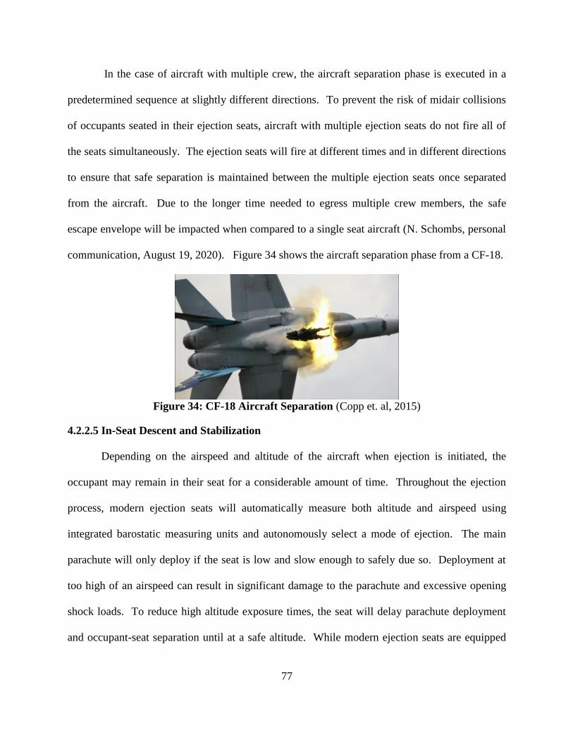
77
In the case of aircraft with multiple crew, the aircraft separation phase is executed in a
predetermined sequence at slightly different directions. To prevent the risk of midair collisions
of occupants seated in their ejection seats, aircraft with multiple ejection seats do not fire all of
the seats simultaneously. The ejection seats will fire at different times and in different directions
to ensure that safe separation is maintained between the multiple ejection seats once separated
from the aircraft. Due to the longer time needed to egress multiple crew members, the safe
escape envelope will be impacted when compared to a single seat aircraft (N. Schombs, personal
communication, August 19, 2020). Figure 34 shows the aircraft separation phase from a CF-18.
Figure 34: CF-18 Aircraft Separation (Copp et. al, 2015)
4.2.2.5 In-Seat Descent and Stabilization
Depending on the airspeed and altitude of the aircraft when ejection is initiated, the
occupant may remain in their seat for a considerable amount of time. Throughout the ejection
process, modern ejection seats will automatically measure both altitude and airspeed using
integrated barostatic measuring units and autonomously select a mode of ejection. The main
parachute will only deploy if the seat is low and slow enough to safely due so. Deployment at
too high of an airspeed can result in significant damage to the parachute and excessive opening
shock loads. To reduce high altitude exposure times, the seat will delay parachute deployment
and occupant-seat separation until at a safe altitude. While modern ejection seats are equipped
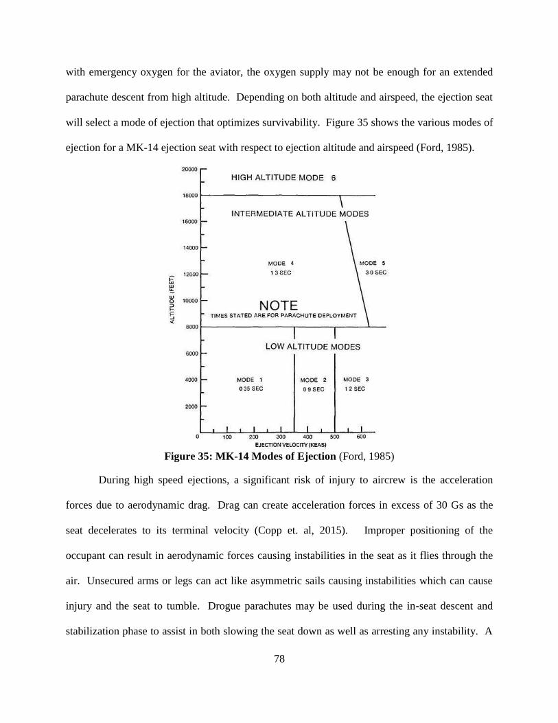
78
with emergency oxygen for the aviator, the oxygen supply may not be enough for an extended
parachute descent from high altitude. Depending on both altitude and airspeed, the ejection seat
will select a mode of ejection that optimizes survivability. Figure 35 shows the various modes of
ejection for a MK-14 ejection seat with respect to ejection altitude and airspeed (Ford, 1985).
Figure 35: MK-14 Modes of Ejection (Ford, 1985)
During high speed ejections, a significant risk of injury to aircrew is the acceleration
forces due to aerodynamic drag. Drag can create acceleration forces in excess of 30 Gs as the
seat decelerates to its terminal velocity (Copp et. al, 2015). Improper positioning of the
occupant can result in aerodynamic forces causing instabilities in the seat as it flies through the
air. Unsecured arms or legs can act like asymmetric sails causing instabilities which can cause
injury and the seat to tumble. Drogue parachutes may be used during the in-seat descent and
stabilization phase to assist in both slowing the seat down as well as arresting any instability. A
79
tumbling seat can cause injuries to the occupant in the same way a flat spin can injure a
parachutist which was discussed in section 4.2.1.2. Another risk of injury during stabilization is
the direction of loads applied to the occupant.
Ideally, the accelerations caused by drag during seat stabilization and descent are mostly
in the longitudinal direction relative to the occupant. Human tolerances to accelerations are the
highest in the longitudinal direction. However, if there is seat instability, the accelerations due to
drag can be experienced in the vertical and lateral directions as the seat tumbles. If ejecting from
a very fast aircraft, the decelerations coupled with an unstable seat can cause compressive
injuries to the spine as well as displace vital organs which can result in serious injury or death
(N. Schombs, personal communication, August 19, 2020).
Seat stabilization is also critical for successful parachute deployment. Main parachute
deployment during tumbling presents similar risks as an unstable parachutist. Parachute lines
can tangle, and the parachute may become entangled in the seat and/or occupant which may
prevent the canopy from inflating properly and result in excessive descent rates.
4.2.2.6 Parachute Deployment
Once the seat is at both a safe altitude and airspeed, modern seats will automatically
deploy the main parachute. If the ejection is in close proximity to the ground, ballistic assistance
may be automatically used to decrease the time required for full parachute canopy inflation. The
risk of injury to an aviator during parachute deployment in an ejection seat is very similar to the
risks of injury of a parachutist. For the risk of injury during parachute deployment refer to
section 4.2.1.3. One unique source of risk for modern ejection seats is the potential for failure of
parachute to deploy due to high altitude.
80
As previously stated, modern ejection seats use barostatic measuring devices to determine
both airspeed and altitude. The system measures altitude by calculating pressure altitude based
on static pressure compared to the standard atmosphere. As a result, the barostatic measurement
unit only measures altitude Above Sea Level (ASL), not AGL. If ejecting in a very high
mountainous area with terrain over 15,000 ft. ASL, the system may not automatically deploy the
main parachute in time to successfully get full canopy inflation. While there are manual
overrides to the automatic parachute deployment system, they are only effective if the aircrew is
conscious and aware of the terrain hazard. If the hazard is not properly recognized or the crew is
incapacitated, an ejection in a mountainous environment with high altitude terrain may result in
blunt force trauma due to failure of the main parachute to deploy.
4.2.2.7 Occupant Seat Separation
It is critical that the occupant remain attached to the seat until it is safe to separate.
Drogue parachutes may be used during the in-seat descent and stabilization phase to both slow
and stabilize the ejection seat. Once the seat has reached a safe speed and altitude, the occupant
will separate from the seat at roughly the same time as main parachute deployment. Failure of
the occupant-seat separation phase could result in excessive descent rates while descending
under the parachute due to the additional weight of the seat. Adverse interactions with the seat
and main parachute can degrade the performance of the parachute system.
4.2.2.8 Parachute Descent
Once the occupant has been separated from the seat and the parachute has successfully
deployed, the risk of injury to the aviator are exactly the same as a parachutist. The risk of injury
during parachute descent, landing, and recovery are outlined in section 4.2.1. For specific risks
of injury during parachute descent, refer to section 4.2.1.4.
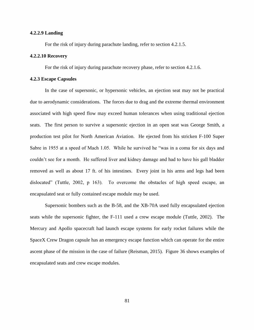
81
4.2.2.9 Landing
For the risk of injury during parachute landing, refer to section 4.2.1.5.
4.2.2.10 Recovery
For the risk of injury during parachute recovery phase, refer to section 4.2.1.6.
4.2.3 Escape Capsules
In the case of supersonic, or hypersonic vehicles, an ejection seat may not be practical
due to aerodynamic considerations. The forces due to drag and the extreme thermal environment
associated with high speed flow may exceed human tolerances when using traditional ejection
seats. The first person to survive a supersonic ejection in an open seat was George Smith, a
production test pilot for North American Aviation. He ejected from his stricken F-100 Super
Sabre in 1955 at a speed of Mach 1.05. While he survived he “was in a coma for six days and
couldn’t see for a month. He suffered liver and kidney damage and had to have his gall bladder
removed as well as about 17 ft. of his intestines. Every joint in his arms and legs had been
dislocated” (Tuttle, 2002, p 163). To overcome the obstacles of high speed escape, an
encapsulated seat or fully contained escape module may be used.
Supersonic bombers such as the B-58, and the XB-70A used fully encapsulated ejection
seats while the supersonic fighter, the F-111 used a crew escape module (Tuttle, 2002). The
Mercury and Apollo spacecraft had launch escape systems for early rocket failures while the
SpaceX Crew Dragon capsule has an emergency escape function which can operate for the entire
ascent phase of the mission in the case of failure (Reisman, 2015). Figure 36 shows examples of
encapsulated seats and crew escape modules.
82
F-111 Crew Escape Module
XB-70 Encapsulated Ejection Seat
Figure 36: Crew Escape Module and Encapsulated Ejection Seat (Tuttle, 2002)
Escape modules share similarities to both parachutes and ejection seats. As a result, they
also share similar survivability concepts. When evaluating survivability, there are five discreet
phases to consider:
1. Vehicle Separation
2. Descent
3. Descent Arrest
4. Landing
5. Recovery
To ensure the survivability of crew using escape capsules, all five phases must be
executed and function properly. If any phase is unsuccessful or malfunctions, it can have a
cascading effect on the remaining phases potentially resulting in serious injury or death. A
successful escape using an escape module starts with the vehicle separation phase.
4.2.3.1 Vehicle Separation
With high speed, high energy vehicles, it may be necessary to completely separate from
the transport vehicle in the case of an emergency to ensure safety of the crew. For rockets
designed to carry human payloads, trajectory deviations or system failures may warrant
separation from the rocket. For supersonic or hypersonic aircraft, failures may require vehicle
83
separation to ensure survivability of the people onboard. Failure to separate from the vehicle
may expose the people onboard to excessive accelerations due to aerodynamic loads, vehicle
instabilities, impact with terrain, or the energies associated with a rocket explosion.
Similar to parachuting, it is critical that during vehicle separation, the process takes place
without any adverse interactions occurring between the escape capsule and vehicle. If clean
vehicle separation doesn’t occur, the capsule thermal protection systems may be damaged, life
support systems may be compromised, or the capsule occupants may be exposed to blunt force
trauma. It is also critical that the vehicle separation phase be initiated within the appropriate safe
escape envelope.
Much like with ejection seats, escape capsules are going to have a safe escape envelope.
The safe escape envelope will be a function of the vehicle’s airspeed, attitude, altitude, and the
performance of the escape capsule itself. Failure to initiate escape within the safe escape
envelope may expose the crew to an increased risk of injury.
4.2.3.2 Descent
After vehicle separation, it is critical that the capsule or escape module have a stable
descent. Aerodynamic interactions with the vehicle during separation may cause instabilities.
Excessive rotation rates or tumbling may expose the occupants of the capsule to accelerations
that can exceed human tolerances. Stability may be accomplished with the assistance of drogue
parachutes or rocket thrusters. During an abort sequence, the SpaceX Crew Dragon’s capsule
accomplishes stability through the use of up to four rockets mounted to the capsule (Reisman,
2015). The rocket thrusters can automatically fire to arrest any instability that may exist in the
vehicle’s flight.
84
4.2.3.3 Descent Arrest
Prior to the escape capsule or module impacting terrain, it is critical that the descent rate
be arrested. Excessive descent rates at landing can expose the capsule occupants to very high
accelerations. Descent arrest can be accomplished through the use of parachutes, rocket motors,
airbag systems, or combinations of various systems. When using parachutes, it is critical that the
parachutes be designed appropriately for the expected deployment speeds. Deploying parachutes
at excessive speeds can cause parachute damage resulting in excessive descent rates. Airbag
systems may be used to arrest descent rates during landing by acting as energy absorbers.
Rockets may be fired at the terminal area of landing to arrest decent rates.
4.2.3.4 Landing
During the landing phase, the survivability considerations for capsules are similar to
those of parachutists. While the capsule may provide protection from the occupants impacting
the ground, man-made hazards in the landing zone still present a risk of injury. Airbags and
inflatable systems may be used to stabilize the capsule and provide buoyancy when impacting
water. Other sources of injury include excessive descent rates at the time of landing.
4.2.3.5 Recovery
Once on the ground, the considerations for escape modules are very similar to post-crash
factors when evaluating CREEP. If parachutes are used to arrest descent rates, the recovery risks
for escape modules are the same for parachutists. For post-crash factors, the risks include
survival factors such as water egress, weather and the local environment, wildlife interactions,
quick access to medical care, and prompt rescue.
85
5.0 Discussion
5.1 CREEP Baseline
Crash survivability started with the pioneer Hugh DeHaven and his four principles. As
the father of crashworthiness, DeHaven’s principles provided the foundation for the modern
survivability standard CREEP. When analyzing a crash, investigators use the acronym to
systematically study and thoroughly evaluate each component. The components of CREEP are
not mutually exclusive and each may rely on other survivability components to ensure that
human tolerances are maintained and survival is accomplished. Each facet of CREEP, container,
restraint, environment, energy absorption, and post-crash factors are complex and may contain
multiple factors and subsystems to consider.
Starting with container, the vehicle must provide protection and maintain survivable
space for occupants throughout a crash event. Container also considers the shedding of high
mass items and designing the vehicle so that it does not crush or plow as methods for providing
protection. Restraint refers to limiting occupant flail and mitigating the energy of the aircraft
occupants throughout a crash. Environment considers the delethalization of the immediate
surroundings and within an occupant’s flail envelope. Energy absorption focuses on reducing
crash loads to within human tolerances. And post-crash factors consider the elements of egress
and survival after the crash event has concluded. The survivability considerations for each
component are summarized below:
Container
o Survivable space must be maintained
o Airframe hardening
Prevent intrusion into aircraft
86
Structure must maintain shape throughout crash
Emergency egress locations hardened
o Retention/Shedding of high mass items
o Structurally designed to prevent plowing
Restraint
o Mitigate energy of occupant throughout crash
o Limit occupant flail
o Must maintain tie-down chain
o Must transmit loads to skeletal structure of occupant
o Should be designed appropriately for application
Environment
o Delethalization of occupant’s surroundings
Keep objects out of flail envelope
Add padding or design to be frangible
o Environment free from toxic fumes
Energy Absorption
o Reduces loads experienced by occupants of aircraft
o Should reduce loads to within human tolerances
Human tolerances may vary based on individual factors
Post-Crash Factors
o Post-Crash fire
Respiratory injury
Thermal injury
87
Toxic gasses
Emergency egress critical to reduce risk of post-crash fire
o Over or under water egress
o Exposure to the elements
Weather/Local Environment
Wildlife
Availability and use of flotations systems
Personal flotation acceptable for warm water
Rafts necessary for cold water immersion
o Quick access to medical care
o Prompt rescue operations
5.2 CREEP Deficiencies
After evaluating the case studies, CREEP was evaluated for each accident to identify
deficiencies in the acronym. Many of the case studies emphasized survivability considerations
that occurred outside of conditions dealing with a crash. For many of the accidents, crashes never
took place. Each additional survivability consideration from the case studies was assigned to one
of the five components of CREEP. Starting with container, Delta Airlines Flight 1288, and
Trans-Canada Airlines Flight 304 emphasized the need for fuselage hardening from high energy
projectiles. The Space Shuttle Columbia STS-107 and Southwest Airlines Flight 1380 accidents
emphasized the need for the vehicle to protect occupants from high speed aerodynamic
environments.
88
5.2.1 Container
For most aircraft, the engines are placed in a position such that if they fail and are not
contained, they may strike the fuselage, potentially injuring the occupants. Due to very high
rotation rates, engine failures can cause significant damage with the potential to result in
catastrophic consequences. During full scale tests on blade strike prevention composite fuselage
shielding, a section of propeller blade weighing 6.8 kilograms was released while traveling at
1120 RPM. Immediately after release, the blades achieved a linear velocity of 162 meters per
second (m/s). At over 160 m/s, the 6.8 kilogram blade had a kinetic energy of 91,094 joules
(Pereira et al, 2016).
When considering the kinetic energy required to cause serious injury, a propeller blade
with over 91,000 joules of energy exceeds established levels by multiple orders of magnitude.
There is a 90% probability of death when being struck in the head with an object having just 150
joules of energy. There is a 90% probability of death when hit in the torso by an object having
500 joules of energy (Henderson, 2010). While the energy of over 91,000 joules is before
contact with the fuselage, without specific shields in place, the structure of an aircraft cabin is
not expected to slow the projectile to safe speeds if striking the fuselage is inevitable.
The high energy components associated with failing engines have a significant potential
to penetrate an aircraft and cause serious injuries. It is important that the engine case and aircraft
fuselage be designed appropriately to prevent aircraft penetration from high energy debris.
While engine cases can be used to contain failed engine components, fuselage shielding may be
required for turboprop or propeller driven aircraft. During Delta Airlines Flight 1288 and Trans-
Canada Airlines Flight 304, failed engine components penetrated the aircraft and struck

89
passengers, resulting in fatal injuries. Expanding the potential for projectiles from failed
engines, another unique threat to aviation is wildlife, specifically birds.
There were roughly 16,000 wildlife strikes reported to the Federal Aviation
Administration (FAA) in 2018 (FAA Wildlife Strike Database, 2020). While wildlife strikes can
cause failure of critical aircraft systems like both engines during the US Airways Flight 1549
accident, bird strikes can also potentially penetrate the aircraft, causing injury to the crew on the
flight deck. Modern aircraft structures and engines are specifically designed to be resistant to
bird strikes. Transport category aircraft are required to not allow any penetration of their
windscreens when impacted with a four pound bird at the aircraft sea level design cruise speed
(Windshields and Windows, 2020). While some design considerations have been made to
protect against bird strikes, objects more rigid than birds or weighing significantly larger than
four pounds still have the potential to penetrate the aircraft and cause injuries. While evaluating
survivability, it is important for the container to protect its occupants from all projectiles during
an accident event. Failure to do so can result in serious injuries and as a result it is an additional
concern for evaluating container in the acronym CREEP.
Another consideration when evaluating container is the protection from the high speed
aerodynamic environment. During the Space Shuttle Columbia STS-107 accident, the shuttle
orbiter broke up at hypersonic speeds in excess of 100,000 ft. in altitude. This exposed the crew
to extreme temperatures and aerodynamic forces. For aerodynamic flow, once speeds exceed
roughly 100 m/s, air will adiabatically compress around the object which results in a temperature
rise (Anderson, 2011). The surrounding gas temperatures of over 10,000 ºF observed during the
shuttle reentry is caused by the aerodynamic adiabatic compression that takes place. As speeds
increase, more adiabatic compression occurs and a greater temperature change is experienced.
90
Supersonic and hypersonic vehicles can experience very high surrounding temperatures. When
in a high speed environment, it is critical that the vehicle maintain structural integrity and
provide protection from the surrounding aerodynamic environment. Failure of the vehicle can
expose the occupants to extremely high temperatures and aerodynamic pressures.
When George Smith ejected at a speed of Mach 1.05 in 1955, he experienced serious
injuries. The aerodynamic forces he was exposed to resulted in dislocation injuries to both of his
arms and legs. He sustained severe internal injuries which ultimately resulted in the loss of 17 ft.
of his intestines (Tuttle, 2002). During the Southwest Airlines 1308 accident, the fatal injuries
experienced by the passenger were a direct result of being exposed to the aerodynamic flow
outside of the aircraft while being restrained to her seat. The aerodynamic environment at high
speeds can potentially cause serious or fatal injuries. In addition to the lack of protection
provided by the vehicle container, Southwest Airlines Flight 1380 and the Space Shuttle
Columbia STS-107 accidents emphasized significant restraint issues.
5.2.2 Restraint
Southwest Airlines Flight 1380 and STS-107 both experienced restraint system issues
and neither restraint problem had to do with the dynamics associated with a crash event. During
Flight 1380, a passenger was not properly restrained. While her restraint did keep her secured to
her seat, it did not properly restrain her upper torso inside the aircraft. While the circumstances
surrounding the accident were certainly unique, had the occupant been properly restrained inside
the aircraft it is unlikely she would have received fatal injuries.
During the Space Shuttle Columbia accident, the restraint systems failed to prevent
injuries before the orbiter broke up or impacted terrain. During the mishap event, it was noted
that there were injuries sustained by the crew indicative of improper torso restraint. The
91
relatively low accelerations experienced as the orbiter began to lose stability did not activate the
automatic locking feature of the inertial reels used on the torso restraints. After the crew became
incapacitated due to the low pressure environment, they were no longer able to react or actively
brace as the aircraft lost control. As accelerations increased, cervical fractures, skull fractures,
and hemorrhages of the neck muscles were experienced indicating violent upper torso flail.
The two accidents emphasize the importance of proper restraint even outside of crash
events. Restraint systems can reduce occupant flail throughout any dynamic event. They can be
effective during loss of control, aerobatic, or emergency events and can prevent injuries prior to
a vehicles impact with terrain. Focusing on a restraint systems use only during a crash can
potentially miss out on other survivability issues that face restraint systems. While some of the
case studies emphasize survivability concepts with container, and restraint, almost all of them
emphasize survivability considerations with the environment.
5.2.3 Environment
A safe local, surrounding environment around all occupants is critical in ensuring
survivability. As previously discussed, the vehicle itself plays a vital role in ensuring a safe
environment by maintaining its container. Failure of the container may expose the occupants to
extreme temperatures, intrusion into the survivable space, and high energy projectiles. But not
all hazards are presented from sources outside the aircraft. Hazards such as extreme
temperatures, high energy projectiles, and low pressures can also be experienced inside the
aircraft.
Occupants in the British Airtours 28M and the STS-107 were exposed to extreme
temperatures. The British Airtours 28M fire created both toxic fumes and the extremely high
temperatures which resulted in fatal injuries. Although the aircraft experienced the engine

92
failure during its takeoff roll and it never became airborne, the ensuing fire resulted in the deaths
of 55 people. Exposure to high temperatures resulted in six of the 55 fatalities. While post-crash
factors in CREEP does consider a post-crash fire and environment considers toxic fumes inflight,
neither evaluate the high temperatures of a fire outside conditions of a crash. Inflight or ground
fires have the potential to expose passengers to both toxic fumes and high temperatures which
can cause serious injuries or death.
The STS-107 crew experienced both extremely high and extremely low temperatures.
Once the crew module broke up, the occupants were exposed to hypersonic airflow. The air
surrounding the crew was thousands of degrees Fahrenheit. After some time, aerodynamic drag
would have arrested the speed of the crew. Once they slowed down, they were exposed to the
very low temperatures of the high altitude environment. At high altitude, the temperature can be
as low as -70 ºF (Anderson, 2011, p. 1074). Injuries due to both high and low temperature
exposures were experienced by the crew of the STS-107. Although the orbiter broke up and no
longer provided protection, the case study illustrates the potential extremes of temperatures
experienced during space flight. To prevent injuries, it is important for systems to be in place to
protect occupants from the high and low extreme temperatures of high speed, high altitude flight.
As already discussed, failure of the container to prevent cabin penetration can expose
occupants to high energy projectiles. But not all projectiles have to originate from sources
outside the aircraft. Objects such as unrestrained cargo or lap-held infants have the potential to
cause serious injury or death during a dynamic event. During the National Airlines Flight 102
accident, vehicles weighing over 12 tons displaced in the aircraft during takeoff ultimately
causing the aircraft to crash. Anyone exposed to the rolling vehicles would have been at risk of
serious injury. United Airlines Flight 232 crashed with multiple occupants of the aircraft
93
unrestrained. The unrestrained passengers became projectiles during the crash, exposing the
passengers themselves and other passengers in the surrounding area to high energy projectiles.
Current federal regulation in the United States allows children under the age of two to be
held on a person’s lap for the duration of a flight. During Flight 232, the lap-held infants were
not successfully restrained by their parents and they became projectiles. As a result of this
accident, the NTSB released a Safety Recommendation on May 30, 1990 specifically
recommending that the FAA “Revise 14 CFR 91, 121 and 135 to require that all occupants be
restrained during takeoff, landing, and turbulent conditions, and that all infants and small
children below the weight of 40 pounds and under the height of 40 inches be restrained in an
approved child restraint system appropriate to their height and weight” (Kolstad, 1990, p. 7).
The safety recommendation emphasized the risks of unrestrained occupants to both themselves
and other people on the aircraft.
The last environmental consideration for survivability was emphasized by both the Red
Bull Stratos project and the STS-107 accident. The low pressure environment associated with
high altitude poses several survivability issues such as barotrauma, decompression sickness,
ebullism, and hypoxia. Barotrauma is caused by the rapid expansion of gas in the body when
decompression occurs. Systems in the body that have trapped gasses such as the middle ear, the
paranasal sinuses, the lungs, and the intestines can be subject to injury or discomfort when rapid
decompression takes place. While barotrauma can be extremely painful, it rarely results in
serious or fatal injuries (Davis, 2008). Decompression sickness however can potentially be more
serious.
Decompression sickness is specifically attributed to the dissolved gasses in the body
coming out of solution and forming bubbles when exposed to rapid decompression. The pure
94
oxygen pre-breathe operation conducted during the Red Bull Stratos project was specifically
aimed at reducing the risk of decompression sickness. It is often referred to as the “bends” and is
commonly associated with diving. Much like during ascent while diving, aviation has the
potential to expose occupants to rapid decompression which can cause decompression sickness.
In the most extreme cases, gas bubbles “within the central nervous system can cause cerebral
ischemia and stroke-like symptoms, and bubbles within the pulmonary vasculature can lead to
complete cardiovascular collapse and death” (Davis, 2008, p. 271). In addition to decompression
sickness, at very high altitudes the low pressure environment can cause ebullism which can also
be fatal.
“Ebullism is the spontaneous evolution of water from liquid to gaseous state in tissues at
an ambient pressure of 47 mmHg or less, where the boiling point of water is less than or equal to
the homeostatic temperature of the human body” (Murray, et. al, 2013, p. 89). The ambient
pressure of 47mmHg is typically experienced at an altitude often referred to as the “Armstrong
Line” of about 63,000 ft. When water begins to evaporate in the body, it causes tissue damage in
the process which can be “characterized by diffuse alveolar damage, tissue edema, and
hemorrhagic lung” (Blue, et. al 2014, p. 532). While decompression sickness is associated with
dissolved gasses in the body, ebullism is associated with evaporating water. When exposed to
pressure altitudes exceeding roughly 63,000 ft. ebullism can result in extensive histologic
damage at the cellular level of the body. It can also result in the same cardiovascular collapse
associated with extreme decompression sickness. Ebullism is often fatal as there are few
treatment options available (Blue, et al, 2014). Ebullism was the cause of death for at least one
of the crew members of the Columbia. The last serious risk associated with low pressure
environments is hypoxia.
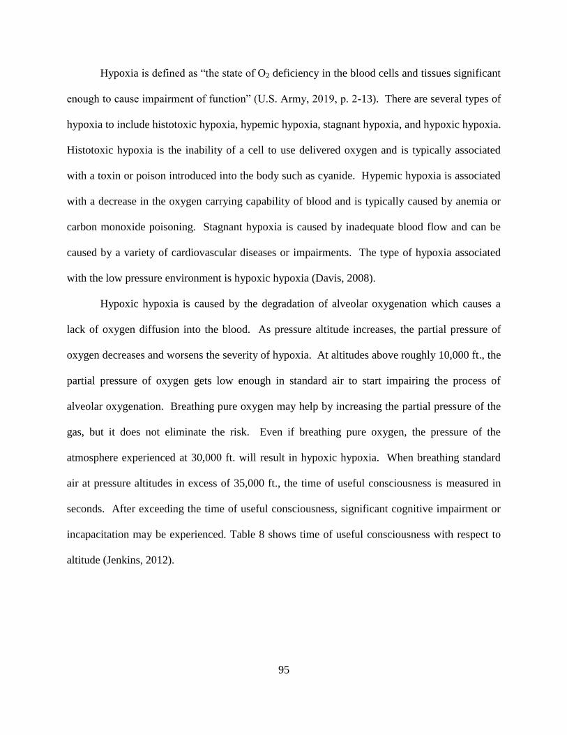
95
Hypoxia is defined as “the state of O2 deficiency in the blood cells and tissues significant
enough to cause impairment of function” (U.S. Army, 2019, p. 2-13). There are several types of
hypoxia to include histotoxic hypoxia, hypemic hypoxia, stagnant hypoxia, and hypoxic hypoxia.
Histotoxic hypoxia is the inability of a cell to use delivered oxygen and is typically associated
with a toxin or poison introduced into the body such as cyanide. Hypemic hypoxia is associated
with a decrease in the oxygen carrying capability of blood and is typically caused by anemia or
carbon monoxide poisoning. Stagnant hypoxia is caused by inadequate blood flow and can be
caused by a variety of cardiovascular diseases or impairments. The type of hypoxia associated
with the low pressure environment is hypoxic hypoxia (Davis, 2008).
Hypoxic hypoxia is caused by the degradation of alveolar oxygenation which causes a
lack of oxygen diffusion into the blood. As pressure altitude increases, the partial pressure of
oxygen decreases and worsens the severity of hypoxia. At altitudes above roughly 10,000 ft., the
partial pressure of oxygen gets low enough in standard air to start impairing the process of
alveolar oxygenation. Breathing pure oxygen may help by increasing the partial pressure of the
gas, but it does not eliminate the risk. Even if breathing pure oxygen, the pressure of the
atmosphere experienced at 30,000 ft. will result in hypoxic hypoxia. When breathing standard
air at pressure altitudes in excess of 35,000 ft., the time of useful consciousness is measured in
seconds. After exceeding the time of useful consciousness, significant cognitive impairment or
incapacitation may be experienced. Table 8 shows time of useful consciousness with respect to
altitude (Jenkins, 2012).
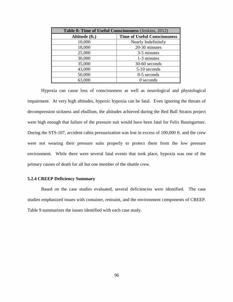
96
Table 8: Time of Useful Consciousness (Jenkins, 2012)
Altitude (ft.) Time of Useful Consciousness
10,000 Nearly Indefinitely
18,000 20-30 minutes
25,000 3-5 minutes
30,000 1-3 minutes
35,000 30-60 seconds
43,000 5-10 seconds
50,000 0-5 seconds
63,000 0 seconds
Hypoxia can cause loss of consciousness as well as neurological and physiological
impairment. At very high altitudes, hypoxic hypoxia can be fatal. Even ignoring the threats of
decompression sickness and ebullism, the altitudes achieved during the Red Bull Stratos project
were high enough that failure of the pressure suit would have been fatal for Felix Baumgartner.
During the STS-107, accident cabin pressurization was lost in excess of 100,000 ft. and the crew
were not wearing their pressure suits properly to protect them from the low pressure
environment. While there were several fatal events that took place, hypoxia was one of the
primary causes of death for all but one member of the shuttle crew.
5.2.4 CREEP Deficiency Summary
Based on the case studies evaluated, several deficiencies were identified. The case
studies emphasized issues with container, restraint, and the environment components of CREEP.
Table 9 summarizes the issues identified with each case study.
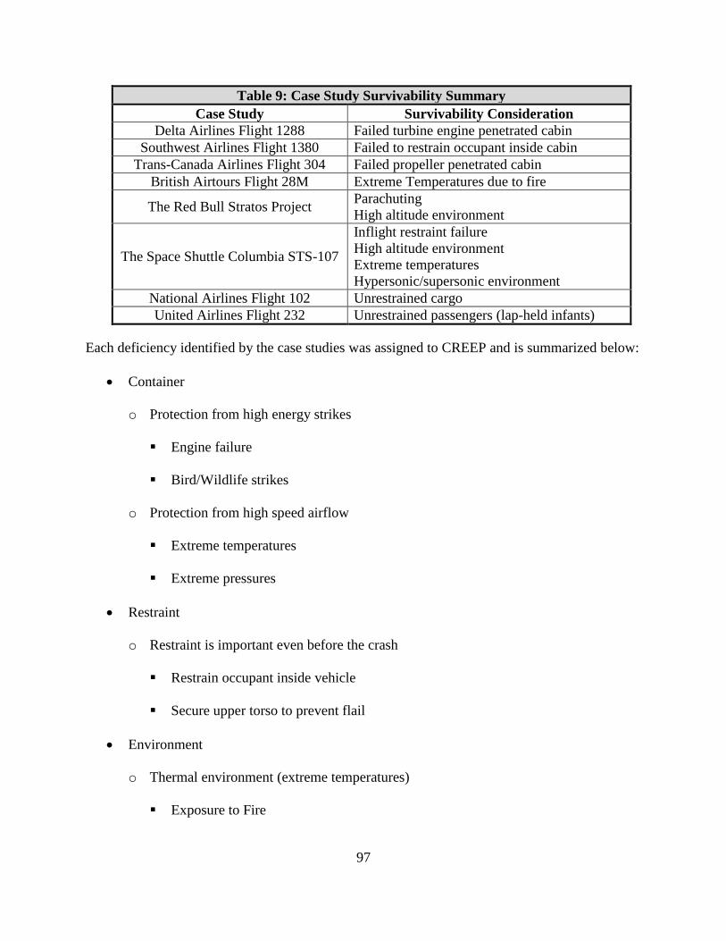
97
Table 9: Case Study Survivability Summary
Case Study Survivability Consideration
Delta Airlines Flight 1288 Failed turbine engine penetrated cabin
Southwest Airlines Flight 1380 Failed to restrain occupant inside cabin
Trans-Canada Airlines Flight 304 Failed propeller penetrated cabin
British Airtours Flight 28M Extreme Temperatures due to fire
The Red Bull Stratos Project Parachuting
High altitude environment
The Space Shuttle Columbia STS-107
Inflight restraint failure
High altitude environment
Extreme temperatures
Hypersonic/supersonic environment
National Airlines Flight 102 Unrestrained cargo
United Airlines Flight 232 Unrestrained passengers (lap-held infants)
Each deficiency identified by the case studies was assigned to CREEP and is summarized below:
Container
o Protection from high energy strikes
Engine failure
Bird/Wildlife strikes
o Protection from high speed airflow
Extreme temperatures
Extreme pressures
Restraint
o Restraint is important even before the crash
Restrain occupant inside vehicle
Secure upper torso to prevent flail
Environment
o Thermal environment (extreme temperatures)
Exposure to Fire
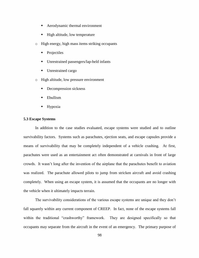
98
Aerodynamic thermal environment
High altitude, low temperature
o High energy, high mass items striking occupants
Projectiles
Unrestrained passengers/lap-held infants
Unrestrained cargo
o High altitude, low pressure environment
Decompression sickness
Ebullism
Hypoxia
5.3 Escape Systems
In addition to the case studies evaluated, escape systems were studied and to outline
survivability factors. Systems such as parachutes, ejection seats, and escape capsules provide a
means of survivability that may be completely independent of a vehicle crashing. At first,
parachutes were used as an entertainment act often demonstrated at carnivals in front of large
crowds. It wasn’t long after the invention of the airplane that the parachutes benefit to aviation
was realized. The parachute allowed pilots to jump from stricken aircraft and avoid crashing
completely. When using an escape system, it is assumed that the occupants are no longer with
the vehicle when it ultimately impacts terrain.
The survivability considerations of the various escape systems are unique and they don’t
fall squarely within any current component of CREEP. In fact, none of the escape systems fall
within the traditional “crashworthy” framework. They are designed specifically so that
occupants may separate from the aircraft in the event of an emergency. The primary purpose of
99
their design is to ensure safe separation and prevent the occupants from going down with the
aircraft ensuring that they avoid the crash all together. The first escape system to be
implemented was the parachute.
5.3.1 Parachuting Summary
Parachutes are most commonly used for the sport of skydiving. Parachutes are also used
as a means of safe escape for pilots who wish to jump from their aircraft in the case of an
emergency. Parachutes are frequently used for aircraft performing hazardous activities such as
acrobatic flight, air racing, and transporting skydivers. Effective bailout is limited to relatively
slow speed aircraft. There are several survivability considerations that should be made when
evaluating parachutes. Parachuting can be separated into six discrete events, each with their own
survivability factors. They are:
Safe separation
o Clear obstacles
o Get to egress door and successfully clear the aircraft
o Egress at appropriate speeds to minimize windblast
Freefall
o Instability
o Midair collisions
o Environment
Hypoxia
Low temperature
Adverse weather
Parachute deployment
100
o Deployment system failure
o Jumper instability or improper positioning
o Excessive speed
o Incorrect packing procedure
o Multiple deployments
o Properly fitting harness
Descent under parachute
o Midair collisions
o Environment
Hypoxia
Low temperature
Adverse weather
Landing
o Terrain features
Impalement injuries
Blunt force trauma
o Man-made landing zone hazards
o Excessive descent rates
o Successful PLF
Recovery
o Failure to secure parachute
Being dragged through landing zone
o Tree landing and fall
101
o Water landings and drowning
o Weather exposure
o Wildlife interaction
o Quick access to medical care
o Prompt rescue
5.3.2 Ejection Seat Summary
Ejection seats are typically used in high performance aircraft commonly owned and
operated by state governments. But not all ejection seat equipped aircraft are owned by
government agencies. In 2012, the NTSB released a Safety Recommendation specifically
addressing the hazards associated with investigating mishaps involving aircraft equipped with
ejection seats. The safety recommendation specifically cites use in Aero Vodochody L39C
aircraft registered to Fighter Town USA, LLC and operated under Part 91 regulations (Hersman,
2012).
There are also cases of military aircraft being demilitarized and sold to private
individuals. A private owner operating as Nalls Aviation Inc. in California, Maryland, owns and
operates AV-8B Harrier aircraft fully equipped with ejection seats. The owner performs at
airshows demonstrating the aircraft’s vertical takeoff and landing capabilities (TheBaynet.com,
2014). There are many survivability considerations that should be evaluated when investigating
an accident involving an ejection seat. The process of a safe ejection can be broken down into
ten discrete events, each with their own survivability factors. They are:
Ejection initiation
o Safe escape envelope
Aircrew positioning
102
Canopy/Hatch jettison/fracturing
o Properly sized aviator
o Properly using ALSS
o Decompressive injuries
Aircraft separation
o Proper aircrew position
o Proper aircrew sizing
o Midair collision
o Flail injuries due to windblast
In-Seat descent and stabilization
o Seat stabilization
Deceleration forces primarily applied longitudinally
Stabilize seat for parachute deployment
Parachute deployment
o Ejection over high altitude terrain
o Deployment system failure
o Jumper instability or improper positioning
o Excessive speed
o Incorrect packing procedure
o Multiple deployments
o Properly fitting harness
Occupant-seat separation
o Excessive descent rates
103
Descent under parachute
o Midair collisions
o Environment
Hypoxia
Low temperature
Adverse weather
Landing
o Terrain features
Impalement injuries
Blunt force trauma
o Man-made landing zone hazards
o Excessive descent rates
o Successful PLF
Recovery
o Failure to secure parachute
Being dragged through landing zone
o Tree landing and fall
o Water landings and drowning
o Weather exposure
o Wildlife interaction
o Quick access to medical care
o Prompt rescue
104
5.3.3 Escape Capsule Summary
Escape capsules are primarily used on very high speed aircraft or rocket propelled
vehicles. They can be used on supersonic fighters, bombers, or rocket propelled space vehicles.
In the final investigation report for the Space Shuttle Columbia, the lack of adequate protection
from vehicle damage and the lack of an escape system were specifically noted as contributing
factors that led to the outcome for the shuttle crew. The report stated “future crewed-vehicle
requirements should incorporate the knowledge gained from the Challenger and Columbia
accidents in assessing the feasibility of vehicles that could ensure crew survival even if the
vehicle is destroyed” (NASA, 2009, p. XXII). For this reason, the new Crew Dragon capsule
designed by SpaceX implements an emergency escape function that can be used at any point
during the launch sequence.
There are several survivability considerations that should be evaluated when investigating
escape capsules. The process of escape using a capsule can be separated into five discrete
events, each with their own survivability factors. They are:
Vehicle separation
o Clear vehicle without damage
o Safe escape envelope
Descent
o Stable descent
Descent arrest
o Excessive speed
Parachute damage
Landing
105
o Landing zone hazards
o Excessive descent rates
Recovery
o Failure to secure parachute
Being dragged through landing zone
o Tree landing and fall
o Water landings and egress
o Weather exposure
o Wildlife interaction
o Quick access to medical care
o Prompt rescue
6.0 Conclusion
CREEP is the modern industry standard for evaluating survivability. As demonstrated
during the literature review, CREEP and survivability are synonymous with crashworthiness. It
is based on the crashworthy pioneer Hugh DeHaven’s four principles and by evaluating
container, restraint, environment, energy absorption, and post-crash factors, investigators can
systemically and methodically evaluate the survivability of an airplane crash. The final
component of CREEP, post-crash factors emphasizes the acronym’s focus on a crash by
explicitly using the word. However, this should not be the case.
There is much more to survivability than just what happens during a vehicles impact with
terrain. Aviation is a constantly evolving and increasingly complex industry. As technology
continues to change and shape the logistics of how people travel, the survivability considerations
that influence that travel should change as well. While DeHaven’s crashworthiness principles
106
established in the 1950s are still very relevant today, they don’t fully capture the complexities of
current aviation systems and neither does CREEP. Companies like Virgin Galactic and SpaceX
are planning to begin commercial passenger space flights within the close of the decade and
NASA is planning on making humans an interplanetary species by sending astronauts to our
neighboring planet Mars. As our aviation systems evolve, so should the methods of conducting
accident analysis. In evaluating CREEP, there are several survivability considerations that aren’t
included in the current acronym.
The case studies and special considerations show that there are many survivability
considerations that are independent of a crash. For many of the accidents studied, the aircraft
didn’t crash and in some cases they didn’t even get airborne. Except for the Red Bull Stratos
project, all of the case studies evaluated involved fatal injuries. The special consideration of
escape systems emphasize that there are many survivability concepts that are completely
independent of crashworthy concepts. Escape systems survivability concepts are completely
independent of a crash. When using escape systems it is assumed that the occupants are no
longer with the vehicle once it impacts terrain. Until now, escape systems were totally separate
and independent of CREEP. By redefining the survivability acronym, it is possible to expand it
to be a more encompassing, comprehensive tool that can be better utilized by accident
investigators.
Currently, when evaluating CREEP, some of the components may have dependent
relationships with other facets while others can be independent. Emergency egress during post-
crash factors relies on the successful activation and use of emergency exits which must be
hardened to ensure they maintain their function by the container. Energy absorption relies on the
restraint systems in the aircraft maintaining the tie-down chain throughout the crash event. But

107
things like quick access to medical care, prompt rescue, and wildlife interaction are independent
of other survivability considerations. In redefining the acronym, this relationship still holds true.
CREEP should be expanded to include survivability considerations that occur outside of a
crash. This includes considerations such as high energy projectile protection, protection from the
high speed aerodynamic environment, protection from extreme temperatures, and the
considerations of a high altitude low pressure environment. The acronym should be also be
redefined to include escape systems. Due to the fundamental nature of energy absorption
occurring during extreme vehicle dynamics, CREEP should be redefined to consider energy
absorption or escape systems. Post-crash factors should be redefined to “post-event factors” to
eliminate the assumption that a crash has taken place. Therefore, the new definition of CREEP is
Container, Restraint, Environment, Energy absorption/Escape, and Post-event factors. The
following is a summary of the factors that influence survivability using the new acronym is:
Container
o Survivable space must be maintained
o Airframe hardening
Prevent intrusion into aircraft
Structure must maintain shape throughout crash
Emergency egress locations hardened
o Retention of high mass items
o Structurally designed to prevent plowing
o Protection from high energy strikes
Engine failure
Bird/wildlife strikes
108
o Protection from high speed airflow
Extreme temperatures
Extreme pressures
Restraint
o Mitigate energy of occupant throughout crash
o Limit occupant flail
Restrain occupant inside vehicle
Secure upper torso
o Must maintain tie-down chain
o Must transmit loads to skeletal structure of occupant
o Should be designed appropriately for application
Environment
o Delethalization of occupant’s surroundings
Keep objects out of flail envelope
Add padding or design to be frangible
o Environment free from toxic fumes
o Thermal environment (extreme temperatures)
Exposure to fire
Aerodynamic thermal environment
High altitude, low temperature
o High energy, high mass items striking occupants
Projectiles
Unrestrained passengers/lap-held infants
109
Unrestrained cargo
Energy Absorption/Escape
Energy Absorption
o Reduces loads experienced by occupants of aircraft
o Should reduce loads to within human tolerances
Human tolerances may vary based on individual factors
Escape
o Safe Separation
Clear obstacles
Get to egress door and successfully clear the aircraft
Egress at appropriate speeds to minimize windblast
Separate from main vehicle without damage
o Freefall
Instability
Midair collisions
Environment
Hypoxia
Decompression sickness
Low temperature
Adverse weather
o Ejection Initiation
Safe escape envelope
Decompressive injuries
110
o Aircrew positioning
o Canopy/Hatch jettison/fracturing
Properly sized aviator
Properly using ALSS
o Aircraft separation
Proper aircrew position
Proper aircrew sizing
Midair collision
Flail injuries due to windblast
o Descent and stabilization
Stable descent
Seat stabilization
Deceleration forces primarily applied longitudinally
Stabilize seat for parachute deployment
o Parachute deployment
Ejection over high altitude terrain
Deployment system failure
Jumper instability or improper positioning
Excessive speed
Incorrect packing procedure
Multiple deployments
Properly fitting harness
o Descent under parachute

111
Midair collisions
Environment
Hypoxia
Low temperature
Adverse weather
o Landing
Terrain features
Impalement injuries
Blunt force trauma
Landing zone hazards
Excessive descent rates
Successful PLF
Post-Event Factors
o Post-event fire
Respiratory injury
Thermal injury
Toxic gasses
Emergency egress critical to reduce risk of post-accident fire
o Over/Under water egress
o Exposure to the elements
Weather/Local Environment
Wildlife
Availability and use of flotations systems
112
Personal flotation acceptable for warm water
Rafts necessary for cold water immersion
o Failure to secure parachute (Escape Systems)
Dragged through landing zone
o Tree landing and fall (Escape Systems)
o Water landings and drowning (Escape Systems)
o Quick access to medical care
o Prompt rescue operations
The new acronym is more comprehensive and it covers a much wider range of aviation
systems. By using the new definition of CREEP, investigators don’t have to just focus on
accidents that involve a crash or an aircraft impacting terrain. The new definition represents an
analysis that was conducted during a snapshot in time. Considering the dynamic nature of
technology as it relates to aviation, accident analysis should be constantly evolving. While
maintaining the acronym CREEP isn’t essential, the analysis of survivability as it relates to
aviation should be a living evolving concept. If other survivability issues are identified in the
future, the survivability tool used should be updated accordingly.
113
7.0 References
Air Accidents Investigation Branch (AAIB). (1989) Report on the accident to Boeing 737-236 series 1,
G-BGJL at Manchester International Airport on 22 August 1985. Retrieved from:
https://www.gov.uk/aaib-reports/8-1988-boeing-737-236-g-bgjl-22-august-1985
Anderson, J. D. (2011). Fundamentals of aerodynamics (5th ed.). New York: McGraw-Hill.
Blue, R. S., Norton, S. C., Law, J., Pattarini, J. M., Antonsen, E. L., Garbino, A., Clark, J. B., & Turney,
M. W (2014). Emergency Medical Support for a Manned Stratospheric Balloon Test Program. Prehospital
and Disaster Medicine, 29(5), 532-537. doi: 10.1017/S1049023X14000958
Civil Aeronautics Board (CAB). (1957) Accident Investigation Report Trans-Canada Air Lines Viscount,
CF-TGR, Flat Rock, Michigan, July 9, 1956 Retrieved from: https://rosap.ntl.bts.gov/cbrowse?pid=dot
%3A32931&parentId=dot%3A32931&hdnSortBy=pub_date_key%20desc&maxResults=50&start=150
Copp, D., Riley, C., Walsh, H,. (Producers) (2015). Survival in the Skies, Episode 02 Ejection Seats
[Television Series]. Arrow International Media and Smithsonian Networks.
Davis, J. R. (2008). Fundamentals of Aerospace Medicine. Philadelphia: Lippincott Williams &
Wilkins.
Definitions, 48 C.F.R §830.2 (2010).
DeHaven, H.,”Accident Survival – Airplane and Passenger Car,” SAE 520016, Society of Automotive
Engineers, Inc., Warrendale, PA, January 1952
Demers, D. (2020). Flying High. Army, 70(1), 32-35.
Ekman, S. K., & Debacker, M. (2018a). Survivability of occupants in commercial passenger aircraft
accidents. Safety Science, 104, 91-98. doi:10.1016/j.ssci.2017.12.039
FAA Wildlife Strike Database, (2020) Retrieved from: https://wildlife.faa.gov/home
Ford, T. (1985). Advanced escape systems. Aircraft Engineering and Aerospace Technology, 57(8), 6-10.
doi:10.1108/eb036142
Gangloff, A. (2013). Safety in accidents: Hugh DeHaven and the development of crash injury studies.
Technology and Culture, 54(1), 40-61. Retrieved from: http://ezproxy.libproxy.db.
erau.edu/login?url=https://search-proquest-com.ezproxy.libproxy.db.erau.edu/docview/
1415750414?accountid=27203
Garbino, A., Blue, R. S., Pattarini, J. M., Law, J., & Clark, J. B. (2014). Physiological monitoring and
analysis of a manned stratospheric balloon test program. Aviation, Space, and Environmental
Medicine, 85(2), 177-182. doi:10.3357/ASEM.3744.2014
Heat Index, Retrieved from: www.weather.gov/safety/heat-index.
Henderson, J., & MINISTRY OF DEFENCE LONDON (UNITED KINGDOM). (2010). Lethality
criteria for debris generated from accidental explosions
114
Hersman, D. A.P,. (2012) National Transportation Safety Board., Safety Recommendation A-12-64
through -67. Washington D.C.
Hurley, T R, Vandenburg, J M . (2002), Small Airplane Crashworthiness Design Guide. Phoenix, AZ,
Kolstad, J. (1990). National Transportation Safety Board., Safety Recommendation A-90-78 and -79.
Washington D.C.
Jenkins, D R., Dressing for Altitude, U.S. Aviation Pressure Suits-Wiley Post to Space Shuttle.
Washington, DC, 2012
Johnson, E. S., Gaydos, S. J., Pavelites, J. J., Kotwal, R. S., &Houk, J. E. (2019). U.S. Army Parachute
Mishap Fatalities: 2010-2015. Aerospace Medicine and Human Performance, 90(7), 637-642. doi:
10.3357/AMHP.5329.2019
Lee, J J., “The Naval Flight Surgeon’s Pocket Reference to Aircraft Mishap Investigation”, Norfolk, VA
2006
Motley, E B., “Aircraft Accident Survivability: Rotary Wing Aircraft”, Forty Third Annual SAFE
Association Symposium, Salt Lake City, Utah, October 2005
Murray, D. H., Pilmanis, A. A., Blue, R. S., Pattarini, J. M., Law, J., Bayne, C. G., Clark, J. B. (2013).
Pathophysiology, prevention, and treatment of ebullism. Aviation, Space, and Environmental Medicine,
84(2), 89-96. doi:10.3357/ASEM.3468.2013
National Aeronautics and Space Administration (NASA). (2003). Columbia Accident Investigation
Board. Retrieved from: https://ntrs.nasa.gov/search.jsp?R=20030066167
National Aeronautics and Space Administration (NASA). (2009). Columbia Crew Survival Investigation
Report NASA/SP-2008-565 Retrieved from: https://ntrs.nasa.gov/search.jsp?R=20090002404
National Aeronautics and Space Administration (NASA). (2014). Loss of Signal, Aeromedical Lessons
Learned from the STS-107 Columbia Space Shuttle Mishap NASA/SP-2014-616 Retrieved from:
https://ntrs.nasa.gov/archive/nasa/casi.ntrs.nasa.gov/20140008287.pdf
National Transportation Safety Board (NTSB). (1990). Aircraft Accident Report, United Airlines Flight
232, McDonnel Douglas DC-10-10, Sioux Gateway Airport, Sioux City, Iowa, July 19, 1989. Retrieved
from: https://www.ntsb.gov/investigations/AccidentReports/Reports/AAR-90-06.pdf
National Transportation Safety Board (NTSB). (1997). Photo 2. Aerial view showing damage to left
fuselage and left engine. . Retrieved from: https://dms.ntsb.gov/pubdms/search/hitlist.cfm?docketID
=8035&CFID=225754&CFTOKEN=33764686d8da1166-37ED8197-5056-942C-9299ED305AB0B817
National Transportation Safety Board (NTSB). (1997). Photo 8. Interior view of left fuselage penetration
damage adjacent to row 37. Retrieved from: https://dms.ntsb.gov/pubdms/search/hitlist.cfm?docketID=
8035&CFID=225754&CFTOKEN=33764686d8da1166-37ED8197-5056-942C-9299ED305AB0B817
115
National Transportation Safety Board (NTSB). (1997). Photo 9. Interior view of left fuselage penetration
damage adjacent to row 37. Retrieved from: https://dms.ntsb.gov/pubdms/search/hitlist.cfm?docketID=
8035&CFID=225754&CFTOKEN=33764686d8da1166-37ED8197-5056-942C-9299ED305AB0B817
National Transportation Safety Board (NTSB). (1997). Survival Factors Factual Report. Docket No. SA-
515. Retrieved from: https://dms.ntsb.gov/pubdms/search/hitlist.cfm?docketID=8035&CFID=225754
&CFTOKEN=33764686d8da1166-37ED8197-5056-942C-9299ED305AB0B817
National Transportation Safety Board (NTSB). (2015) Aircraft Accident Report, Steep Climb and
Uncontrolled Descent During Takeoff, National Air Cargo, Inc. , dba National Airlines, Boeing747 400
BCF, N949CA, Bagram, Afghanistan, April 29, 2013. Retrieved from: https://www.ntsb.gov/
investigations/AccidentReports/Reports/AAR1501.pdf
National Transportation Safety Board (NTSB). (2018) Survival Factors. Retrieved from:
https://dms.ntsb.gov/pubdms/search/hitlist.cfm?docketID=61786&CFID=226121&CFTOKEN
=834bae9b3e6f3464-3BB09DC2-5056-942C-92BAD786475894A5
National Transportation Safety Board (NTSB). (2019) Aircraft Accident Report, Left Engine Failure and
Susbequent Depressurization, Southwest Airlines Flight 1380, Boeing 737-7h4, N772SW, Philadelphia,
Pennsylvania, April 17, 2018. Retrieved from: https://www.ntsb.gov/investigations/AccidentReports/
Reports/AAR1903.pdf
National Transportation Safety Board (NTSB). (2009). Emergency Response Factual Report of
Investigation. Exhibit Number 2-C. Retrieved from: https://dms.ntsb.gov/pubdmss/search/
hitlist.cfm?docketID=47230&CFID=3220191&CFTOKEN=1dd0d8535b59c547-1A2A02DE-E588-
F7B5-C608B023F5F9BC71
Newman, D. G. (2014;2017). Flying fast jets: Human factors and performance limitations (1st ed.).
Burlington, Vermont; Farnham, Surrey, England;: Ashgate. doi:10.1201/9781315582542
Shanahan, D F., “Basic Principles of Crashworthiness”, North Atlantic Treaty Organization (NATO),
Research and Technology Organization (RTO) Lecture Series, Madrid, Spain, October 2004
Pereira, J. M., Emmerling, W., Seng, S., Frankenberger, C., Ruggeri, C. R., Revilock, D. M., & Carney,
K. S. (2016). Analysis and testing of a composite fuselage shield for open rotor engine blade-out
protection. Hampton: NASA/Langley Research Center.
Pretor-Pinney, G., Sanderson, B., & Cloud Appreciation Society. (2007). The cloudspotter's guide: The
science, history, and culture of clouds (Perigee trade paperback ed.). New York: Berkley Pub. Group.
Red Bull. (2020). Red Bull Stratos. Retrieved from: https://www.Red Bull.com/us-en/projects/red-bull-
stratos
Reisman, G., (2015). "Statement of Garrett Reisman, Director of Crew Operations, Space Explorations
Technologies Corp. (SpaceX) before the Subcommittee on Space, Committee on Science, Space, and
Technology, U.S. House of Representatives" . United States House of Representatives, Committee on
Science, Space, and Technology. Retrieved from: https://science.house.gov/imo/
media/doc/Reisman%20Testimony.pdf.
116
Shanahan, D F., “Human Tolerance and Crash Survivability”, North Atlantic Treaty Organization
(NATO), Research and Technology Organization (RTO) Lecture Series, Madrid, Spain, October 2004
Simula Inc., “Aircraft Crash Survival Design Guide, Volume 2. Aircraft Design Crash Impact Conditions
and Human Tolerance”. United States Army Aviation Systems Command (USAAVSCOM) Technical
Report TR-89-D-11C, Phoenix, AZ, December 1989.
Simula Inc., “Aircraft Crash Survival Design Guide, Volume 3. Aircraft Structural Crash Resistance”.
United States Army Aviation Systems Command (USAAVSCOM) Technical Report TR-89-D-22C,
Phoenix, AZ, December 1989.
Simula Inc., “Aircraft Crash Survival Design Guide, Volume 4. Aircraft Seats, Restraints, Litters, Aand
Cockpit/Cabin Delethalization”. United States Army Aviation Systems Command (USAAVSCOM)
Technical Report TR-89-D-22D, Phoenix, AZ, December 1989.
Simula Inc., “Aircraft Crash Survival Design Guide, Volume 5. Aircraft Postcrash Survival”. United
States Army Aviation Systems Command (USAAVSCOM) Technical Report TR-89-D-22E, Phoenix,
AZ, December 1989.
Taber, M J., “Crash Attenuating Seats: Effects on Helicopter Underwater Escape Performance”, Survival
Systems Limited, Dartmouth, NS, Canada, March 2013
Taneja, Narinder; Wiegman, Douglas A. “Analysis of Injuries among Pilots Killed in Fatal Helicopter
Accidents”. Aviation, Space, and Environmental Medicine, April 2003
TheBayNet.Com, (2014) Second Harrier Jet Added to Nalls Aviation Fleet. Retrieved from:
https://www.thebaynet.com/articles/1114/second-harrier-jet-added-to-nalls-aviation-fleet.html
Tintinalli, Judith E. (2010). “Emergency Medicine: A Comprehensive Study Guide (Emergency
Medicine)”. New York: McGraw-Hill Companies. ISBN 978-0-07-148480-0.
Tuttle, J. (2002). Eject: The complete history of U.S. aircraft escape systems. St. Paul, Minn: MBI Pub.
Co.
United States Army, (2018). Aeromedical Training for Flight Personnel, TC 3-04.93,. Washington D.C.
United States. U.S. Coast Guard. National Search and Rescue Manual. Volume 1: National Search and
Rescue System. Washington D.C, August 1986
United States. The Department of the Navy Bureau of Medicine and Surgery, & Naval Aerospace
Medical Institute (U.S.). U.S. Naval Flight Surgeon's Manual (3rd ed.). Pensacola, Florida; Washington
D.C., 1991
Westman, A., & Bjornstig, U. (2005). Fatalities in Swedish Skydiving. Accident Analysis and Prevention,
37(6). 1040-1048. doi:10.1016/j.aap.2005.06.002
What Parachute Types Are There, (2019) Retrieved from: https://www.longislandskydiving.com /about-
skydiving-long-island/articles/what-parachute-types-are-there/
Windshields and Windows, 14 CFR § 25.775 (2020).