Embed Size (px)
Citation preview
UCRL-JC- 125488 PREPRINT
Creep Fracture During Solute-Drag Creep and Superplastic Deformation
Eric M. Taleff Donald R. Lesuer ’. Chol K. Syn
Gregory A. Henshall
This paper was prepared for submittal to the
February 9-13,1997 Orlando, FL
The Minerals, Metals and Materials Society Annual Me
permission of the author. -
DISCLAIMER
Portions of this document may be illegible in electronic image products. b a g s are produced from the best available original document.
Creep Fracture During Solute-Drag Creep and Superplastic Deformation
Eric M. Taleff l, Donald R. Lesuer 2, Chol K. Syn 2, and Gregory A. Henshall
1. The University of Texas at Austin, Department of Aerospace Engineering and Engineering Mechanics, Austin, TX 78712.
2. Lawrence Livermore National Laboratory, Manufacturing and Materials Engineering Division, Livermore, CA 94550.
3. Hewlett-Packard Laboratories, 1501 Page Mill Road, Palo Alto, CA 94304.
Abstract
Creep fracture behavior has been studied in A1-Mg and Al-Mg-Mn alloys undergoing solute-drag creep and in microduplex stainless steel undergoing both solute-drag creep and superplastic deformation. Failure in these materials is found to be controlled by two mechanisms, neck formation and cavitation. The mechanism of creep fracture dur- ing solute-drag creep in A1-Mg is found to change from necking-controlled fracture to cavitation-controlled fracture as Mn content is increased. Binary Al-Mg material fails by neck formation during solute-drag creep, and cavities are formed primarily in the neck region due to high hydrostatic stresses. Ternary alloys of Al-Mg-Mn containing 0.25 and 0.50 wt pct Mn exhibit more uniform cavitation, with the 0.50Mn alloy clearly failing by cavity interlinkage. Failure in the microduplex stainless steel is dominated by neck formation during solute-drag creep deformation but is controlled by cavity growth and interlinkage during superplastic deformation. Cavitation was measured at several strains, and found to increase as an exponential function of strain. An important aspect of cavity growth in the stainless steel is the long latency time before significant cavitation occurs. For a short latency period, cavitation acts to significantly reduce ductility below that allowed by neck growth alone. This effect is most pronounced in materials with a high strain-rate sensitivity, for which neck growth occurs very slowly.
’
,
Introduction
It has long been known that both neck development and cavitation are factors which control tensile ductility. Previous investigations of Al-Mg and Al-Mg-Mn materials have shown a transition in behavior between necking-controlled and cavitation-controlled failure mechanisms with increasing Mn additions [l-51. These data are of particular interest because deformation occurs by solute-drag creep, which leads to enhanced ductilities of up to 300% when failure is controlled by necking alone. Solute-drag creep provides a low stress exponent of n = 3, causing slow neck growth. This effect is analogous to superplasticity, where the stress exponent is n = 2 because of a grain-boundary-sliding creep process. Solutedrag creep is not dependent on grain size, unlike grain-boundary- sliding creep. The requirement of a h e , stable grain size to achieve grain-boundary sliding is a major contributor to the high cost of superplastic materials. These results are significant because materials with enhanced ductilities (100-300%) from solute-drag creep could be used in superplastic forming operations, and would be much less expensive than current superplastic materials. Because cavitation markedly reduces the ductilities of these materials, an understanding leading to its prevention is of great interest.
Experimental data from several aluminum alloys subject to solute-drag creep are pre- sented. These include two binary A1-Mg alloys (A1-2.8Mg and Al-5.5Mg) and two ternary Al-Mg-Mn alloys (A1-3Mg-0.25Mn and A1-3Mg-0.5Mn). Mechanical testing and mi- croscopy data are used to correlate cavitation behavior during solute-drag creep with alloy content. Data from a microduplex stainless steel, Nitronic 19D, are also presented. This material is of particular interest because it deforms by a solutedrag creep process at temperatures of 950°C and below and deforms by a grain-boundary sliding process at temperatures of 1000°C and above [6]. Mechanical testing and microscopy are used to study cavitation behavior in this material during deformation by each of these creep mechanisms. Two creep mechanisms occur because of a phase transformation from 7 + o at low temperatures to 7 + S at temperatures of approximately 1000°C and above [SI.
Experimental Procedure
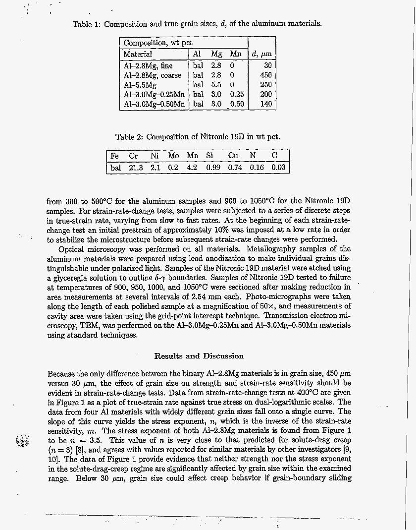
The four aluminum alloys of this study were cast by Kaiser Aluminum Center for Tech- nology to have low impurity contents. 'Qpical processing included homogenization after casting, quenching from the homogenization temperature, then either upset forging and warm rolling or simply warm rolling. One alloy, A1-2.8Mg, was specifically processed to create two materials with different grain sizes. The composition of primary elements and measured grain sizes in each aluminum material are given in Table 1. True grain sizes are reported using the relationship between true grain size, d, and linear-intercept grain size,
as given by d = 1.75g [7]. The AI-3.OMg-0.50Mn material exhibits a bimodal grain size distribution; the most dominant grain size is reported in Table 1. The Nitronic 19D material was obtained from Armco Research and Technology in sheet form hot rolled at 1270°C. The composition of this material is given in Table 2. The grain size of the Ni- tronic 19D after processing was measured to be d = 26 pm. The microstructure consists of an essentially continuous matrix of &ferrite with islands of 7, austenite.
The materials were tested in tension at elevated temperatures by two types of me- chanical tests , elongation-t o-failure and strain-rat e-change tests. For elong at ion-t o-failure tests, samples were pulled at a constant true-strain rate until failure. Constant values of true-strain rate were maintained by using a computer-controlled, screw-driven testing ma- chine. Elongation-to-failure and strain-rate-change tests were conducted at temperatures
I '
Composition, wt pct Material Al Mg Mn A1-2.8Mg, fine bal 2.8 0 Al-2.8Mg, coarse bal 2.8 0 Al-5.5Mg bal 5.5 0 Al-3.OMg-0.25Mn bal 3.0 0.25 Al-3.OMg-0.50Mn bal 3.0 0.50
Table 1: Composition and true grain sizes, d, of the aluminum materials.
d , p m 30
450 250 200 140
Table 2: Composition of Nitronic 19D in wt pct.
Fe Cr Ni Mo Mn Si Cu N C bal 21.3 2.1 0.2 4.2 0.99 0.74 0.16 0.03
from 300 to 500°C for the aluminum samples and 900 to 1050°C for the Nitronic 19D samples. For strain-rate-change tests, samples were subjected to a series of discrete steps in true-strain rate, varying from slow to fast rates. At the beginning of each strain-rate- change test an initial prestrain of approximately 10% was imposed at a low rate in order to stabilize the microstructure before subsequent strain-rate changes were performed.
Optical microscopy was performed on all materials. Metallography samples of the aluminum materials were prepared using lead anodization to make individual grains dis- tinguishable under polarized light. Samples of the Nitronic 19D material were etched using a glyceregia solution to outline 6-7 boundaries. Samples of Nitronic 19D tested to failure at temperatures of 900, 950, 1000, and 1050°C were sectioned after making reduction in area measurements at several intervals of 2.54 mm each. Photo-micrographs were taken along the length of each polished sample at a magnification of 50x, and measurements of cavity area were taken using the grid-point intercept technique. Transmission electron mi- croscopy, TEM, was performed on the Al-3.OMg-0.25Mn and Al-3.OMg-0.50Mn materials using standard techniques.
,e I '
'
Results and Discussion
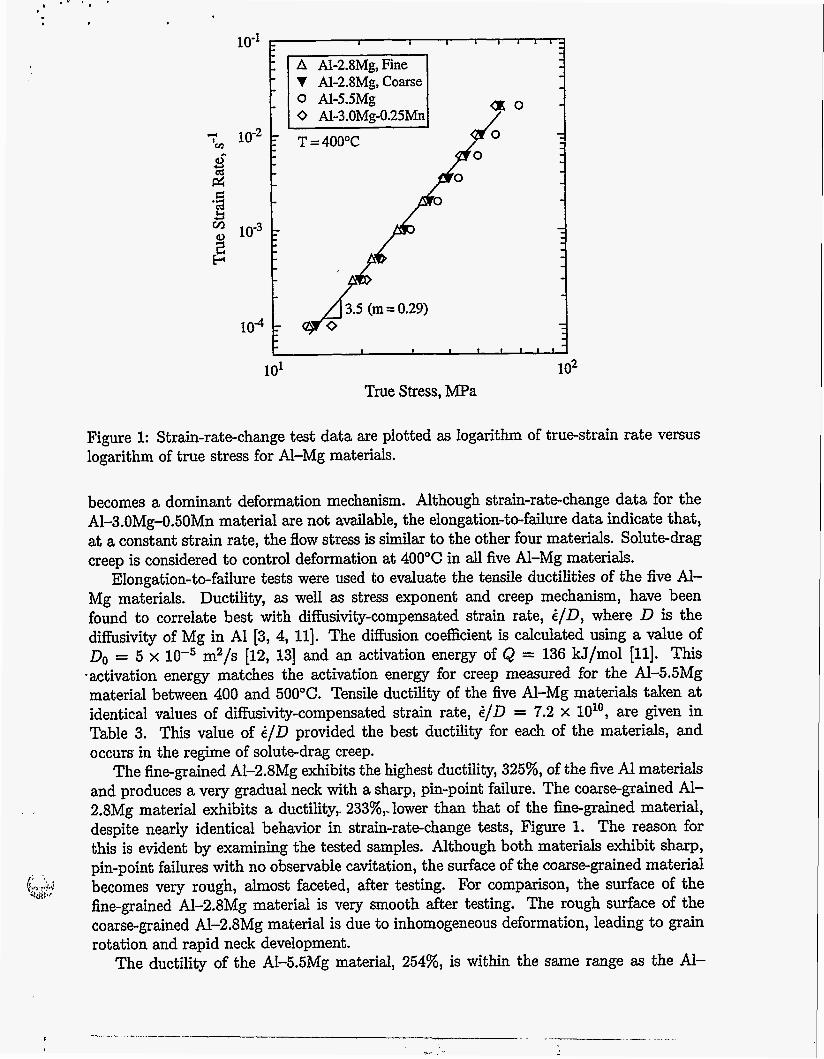
Because the only difference between the binary A1-2.8Mg materials is in grain size, 450 pm versus 30 pm, the effect of grain size on strength and strain-rate sensitivity should be evident in strain-rate-change tests. Data from strain-rate-change tests at 400°C are given in Figure 1 as a plot of true-strain rate against true stress on dual-logarithmic scales. The data from four Al materials with widely different grain sizes fall onto a single curve. The slope of this curve yields the stress exponent, n, which is the inverse of the strain-rate sensitivity, m. The stress exponent of both A1-2.8Mg materials is found from Figure 1 to be n = 3.5. This value of n is very close to that predicted for solute-drag creep (n = 3) [8], and agrees with values reported for similar materials by other investigators [9, lo]. The data of Figure 1 provide evidence that neither strength nor the stress exponent in the solute-drag-creep regime are significantly affected by grain size within the examined range. Below 30 pm, grain size could affect creep behavior if grain-boundary sliding
10''
d Y
2
104
Figure 1: Strain-rate-change test data are plotted as logarithm of true-strain rate versus logarithm of true stress for Al-Mg materials.
becomes a dominant deformation mechanism. Although strain-rate-change data for the A1-3.OMg-0.50Mn material are not available, the elongation-to-failure data indicate that, at a constant strain rate, the flow stress is similar to the other four materials. Solutedrag creep is considered to control deformation at 400°C in all five Al-Mg materials.
Elongation-to-failure tests were used to evaluate the tensile ductilities of the five Al- Mg materials. Ductility, as well as stress exponent and creep mechanism, have been found to correlate best with diffisivity-compensated strain rate, i / D , where D is the diffusivity of Mg in A1 [3, 4, 111. The diffusion coefficient is calculated using a value of Do = 5 x m2/s [12, 131 and an activation energy of Q = 136 kJ/mol [ll]. This
.activation energy matches the activation energy for creep measured for the Al-5.5Mg material between 400 and 500°C. Tensile ductility of the five Al-Mg materials taken at identical values of dihivity-compensated strain rate, i/D = 7.2 x 1O1O, are given in Table 3. This value of C/D provided the best ductility for each of the materials, and occurs in the regime of solute-drag creep.
The fine-grained Al-2.8Mg exhibits the highest ductility, 325%, of the five Al materials and produces a very gradual neck with a sharp, pin-point failure. The coarse-grained Al- 2.8Mg material exhibits a ductility, 233%,-lower than that of the he-grained material, despite nearly identical behavior in strain-rate-change tests, Figure 1. The reason for this is evident by examining the tested samples. Although both materials exhibit sharp, pin-point failures with no observable cavitation, the surface of the coarse-grained material becomes very rough, almost faceted, after testing. For compaison, the surface of the fine-grained Al-2.8Mg material is very smooth after testing. The rough surface of the coarse-grained A1-2.8Mg material is due to inhomogeneous deformation, leading to grain rotation and rapid neck development.
The ductility of the AI-5.5Mg material, 254%, is within the same range as the Al-
, ,
, . &.r!,J .41d**.
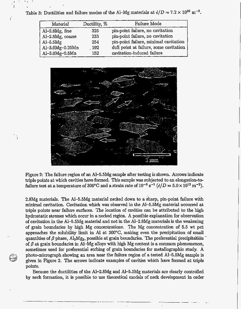
Table 3: Ductilities and failure modes of the Al-Mg materials at i/D = 7.2 x 1O1O m-2.
Material Ductility, % Failure Mode A1-2.8Mg, fine 325 pin-point failure, no cavitation A1-2.8Mg, coarse 233 pin-point failure, no Cavitation AI-5.5Mg 254 pin-point failure, minimal cavitation A1-3.OMg-0.25Mn - 192 dull point at failure, some cavitation A1-3 .OMg-O.SMn 152 cavitation-induced failure
Figure 2: The failure region of an A1-5.5Mg sample after testing is shown. Arrows indicate triple points at which cavities have formed. This sample was subjected to an elongation-to- failure test at a temperature of 300°C and a strain rate of s-l (Z/D = 5.0 x 10¹³ m-2).
2.8Mg materials. The A1-5.5Mg material necked down to a sharp, pin-point failure with minimal cavitation. Cavitation which was observed in the Al-5.5Mg material occurred at triple points near failure surfaces. The location of cavities can be attributed to the high hydrostatic stresses which occur in a necked region. A possible explanation for observation of cavitation in the A1-5.5Mg material and not in the AI-2.8Mg materials is the weakening of grain boundaries by high Mg concentrations. The Mg concentration of 5.5 wt pct approaches the solubility limit in A1 at 3OO0C, making even the precipitation of small quantities of p phase, A13Mg2, possible at' grain boundirik. 'The preferential precipitation -' of p at grain boundaries in AI-Mg alloys with high Mg content is a common phenomenon, sometimes used for preferential etching of grain boundaries for metallographic study. A photo-micrograph showing an area near the failure region of a tested A1-5.5Mg sample is given in Figure 2. The arrows indicate examples of cavities which have formed at triple points.
Because the ductilities of the Al-2.8Mg and Al-5.5Mg materials are clearly controlled by neck formation, it is possible to use theoretical models of neck development in order
500
400
u
300
3 s 200 Frl
M E
100
0 0 0.1 0.2 0.3 0.4 0.5
’ m= Ifn
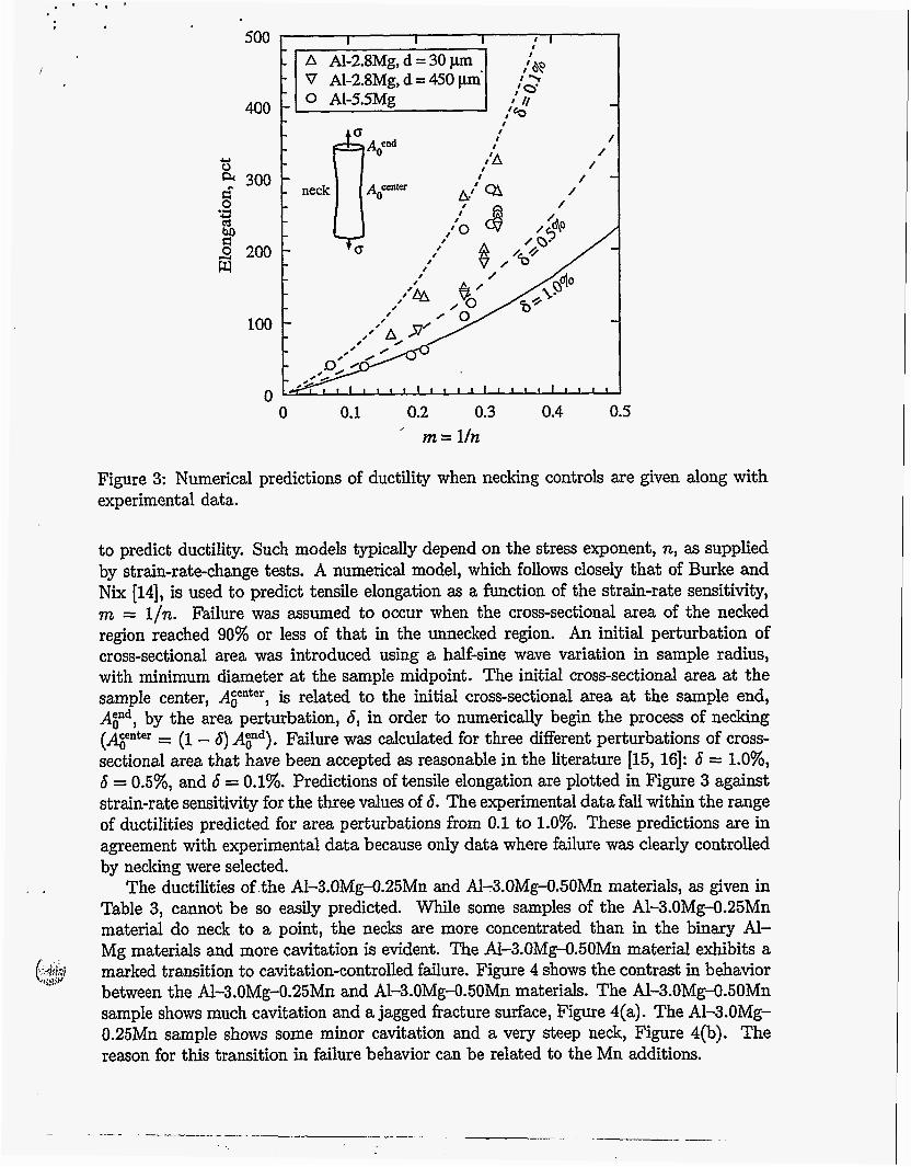
Figure 3: Numerical predictions of ductility when necking controls are given along with experimental data.
to predict ductility. Such models typically depend on the stress exponent, n, as supplied by strain-rate-change tests. A numerical model, which follows closely that of Burke and Nix [14], is used to predict tensile elongation as a function of the strain-rate sensitivity, m = l/n. Failure was assumed to occur when the cross-sectional area of the necked region reached 90% or less of that in the unnecked region. An initial perturbation of cross-sectional area was introduced using a half-sine wave variation in sample radius, with minimum diameter at the sample midpoint. The initial cross-sectional area at the sample center, AFter, is related to the initial cross-sectional area at the sample end, AYd, by the area perturbation, 6, in order to numerically begin the process of necking (ATter = (1 - S) AGnd). Failure was calculated for three different perturbations of cross- sectional area that have been accepted as reasonable in the literature [15, 161: 6 = l.O%, S = 0.5%, and S = 0.1%. Predictions of tensile elongation are plotted in Figure 3 against strain-rate sensitivity for the three values of 6. The experimental data fall within the range of ductilities predicted for area perturbations from 0.1 to 1.0%. These predictions are in agreement with experimental data because only data where failure was clearly controlled by necking were selected.
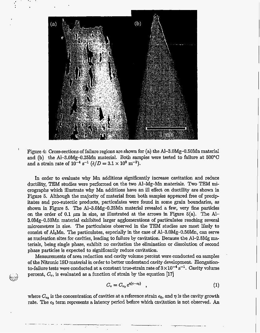
The ductilities of .the Al-3.OMg-0.25Mn and Al-3.OMg-0.50Mn materials, as given in Table 3, cannot be so easily predicted. While some samples of the A1-3.OMg-0.25Mn material do neck to a point, the necks are more concentrated than in the binary Al- Mg materials and more cavitation is evident. The A-3.OMg-0.50Mn material exhibits a marked transition to cavitation-controlled fdure. Figure 4 shows the contrast in behavior between the Al-3.OMg-0.25Mn and A1-3.OMg-0.50Mn materials. The Al-3.OMg-0.50Mn sample shows much cavitation and a jagged fracture surface, Figure 4(a). The AI-3.0Mg- 0.25Mn sample shows some minor cavitation and a very steep neck, Figure 4(b). The reason for this transition in failure behavior can be related to the Mn additions.
, .
($$
. . .
I
Figure 4 Cross-sections of failure regions are shown for (a) the AI-3.OMg-0.50Mn material and (b) the Al-3.OMg-0.25Mn material. Both samples were tested to failure at 500°C and a strain rate of s-l ( i / D = 3.1 x lo9 m-2).
In order to evaluate why Mn additions signifkantly increase cavitation and reduce ductility, TEM studies were performed on the two Al-Mg-Mn materials. Two TEM rni- crographs which illustrate why Mn additions have an ill effect on ductility are shown in Figure 5. Although the majority of material from both samples appeared free of precip- itates and pro-eutectic products, particulates were found in some grain boundaries, as shown in Figure 5. The A1-3.OMg-0.25Mn material revealed a few, very fine particles on the order of 0.1 pm in size, as illustrated at the arrows in Figure 5(a). The Al- 3.OMg-0.50Mn material exhibited larger agglomerations of particulates reaching several micrometers in size. The particulates observed in the TEM studies are most likely to consist of AIGMn. The particulates, especially in the case of Al-3.OMg-0.50Mn, can serve as nucleation sites for cavities, leading to failure by cavitation. Because the AI-2.8Mg ma- terials, being single phase, exhibit no cavitation the elimination or dissolution of second phase particles is expected to significantly reduce cavitation.
Measurements of area reduction and cavity volume percent were conducted on samples of the Nitronic 19D material in order to better understand cavity development. Elongation- to-failure tests were conducted at a constant true-strain rate of 3 x s-'. Cavity volume percent, C,, is evaluated as a function of strain by the equation [17]
where Cvo is the concentration of cavities at a reference strain EO, and 7 is the cavity growth rate. The EO term represents a latency period before which cavitation is not observed. An
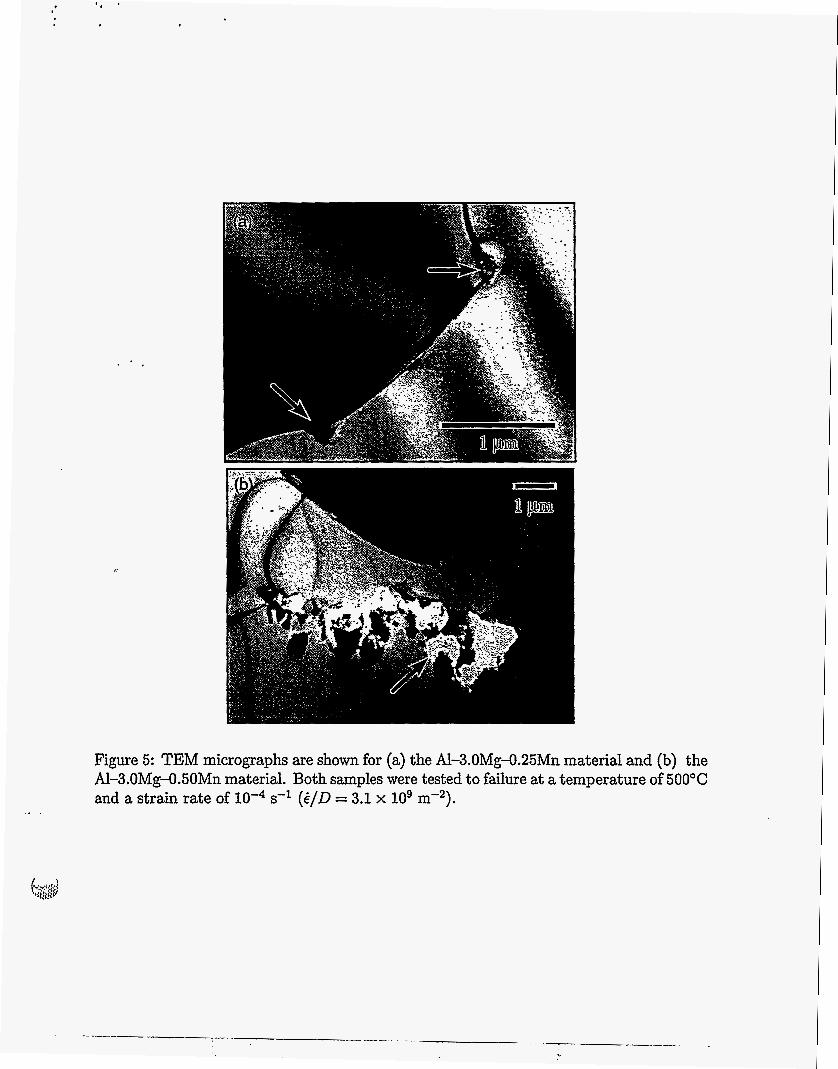
Figure 5: TEM micrographs are shown for (a) the Al-3.OMg-0.25Mn material and (b) the A1-3.OMg-0.50Mn material. Both samples were tested to failure at a temperature of 500°C and a strain rate of lo-* s-l (i/D = 3.1 x lo9 m-2).
20
c1
3 $
P
pc a)
e 5 10
b s u ..I(
0 0 1 2 3
True Strain from Area Reduction
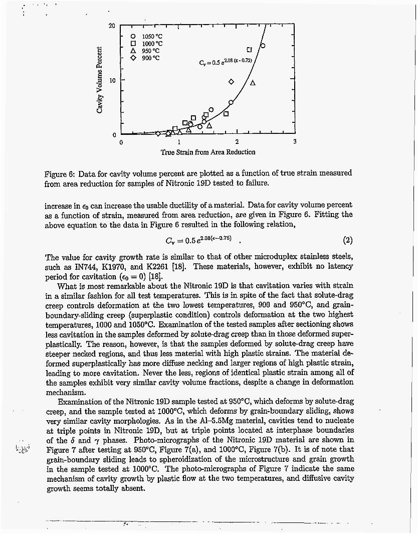
Figure 6: Data for cavity volume percent are plotted as a function of true strain measured from area reduction for samples of Nitronic 19D tested to failure.
increase in €0 can increase the usable ductility of a material. Data for cavity volume percent as a function of strain, measured from area reduction, are given in Figure 6. Fitting the above equation to the data in Figure 6 resulted in the following relation,
(2) c,- - 0 . 5 e2.08(~-0.75)
The value for cavity growth rate is similar to that of other microduplex stainless steels, such as IN744, K1970, and K2261 [18]. These materials, however, exhibit no latency period for cavitation (€0 = 0) [MI.
What is most remarkable about the Nitronic 19D is that cavitation varies with strain in a similar fashion for all test temperatures. This is in spite of the fact that solute-drag creep controIs deformation at the two lowest temperatures, 900 and 950"C, and grain- boundary-sliding creep (superplastic condition) controls deformation at the two highest temperatures, 1000 and 1050°C. Examination of the tested samples after sectioning shows less cavitation in the samples deformed by solute-drag creep than in those deformed super- plastically. The reason, however, is that the samples deformed by solute-drag creep have steeper necked regions, and thus less material with high plastic strains. The material de- formed superplastically has more diffuse necking and larger regions of high plastic strain, leading to more cavitation. Never the less, regions of identical plastic strain among all of the samples exhibit very similar cavity volume fractions, despite a change in deformation mechanism.
Examination of the Nitronic 19D sample tested at 950"C, which deforms by solute-drag creep, and the sample tested at lOOO"C, which deforms by grabboundary sliding, shows very similar cavity morphologies. As in the Al-5.5Mg material, cavities tend to nucleate at triple points in Nitronic 19D, but at triple points located at interphase boundaries of the 6 and 7 phases. Photo-micrographs of the Nitronic 19D material are shown in Figure 7 after testing at 950"C, Figure 7(a), and lOOO"C, Figure 7(b). It is of note that grain-boundary sliding leads to spheroidization of the microstructure and grain growth in the sample tested at 1000°C. The photo-micrographs of Figure 7 indicate the same mechanism of cavity growth by plastic flow at the two temperatures, and diffusive cavity growth seems totally absent.
1, .*L, , j;?;i
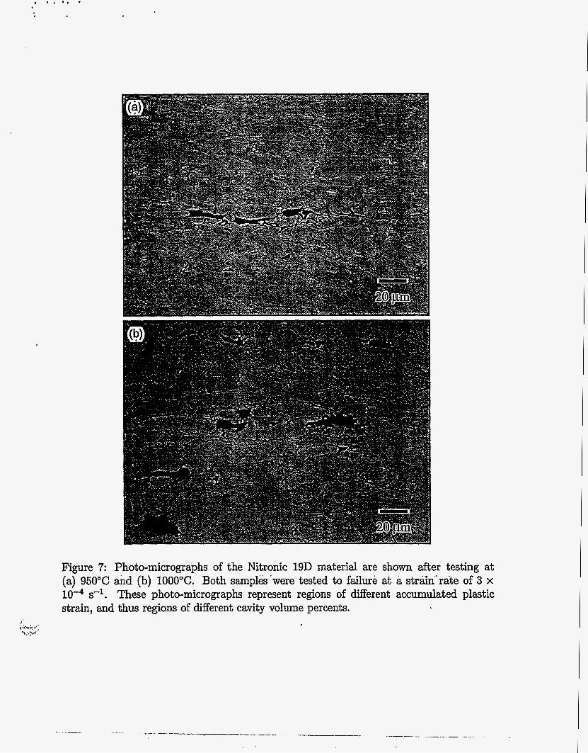
Figure 7: Photo-micrographs of the Nitronic 19D material are shown after testing at (a) 950°C and (b) 1000°C. Both samplkk'were tested to failure at a striin'.rate of 3 x
s-l. These photo-micrographs represent regions of different accumulated plastic strain, and thus regions of different cavity volume percents.
Conclusions
1. Solute-drag creep in A1-Mg alloys can lead to enhanced ductilities of up to 325% when failure is controlled by necking alone. Theoretical predictions of tensile ductil- ity based on neck growth correspond well with experimental data for this case.
2. Additions of Mn to AI-3.0Mg alloys lead to particulates which are associated with in- creased cavitation. Additions of 0.25 w t pct Mn yield very small, infrequent particles which cause only minor cavitation. Additions of 0.50 wt pct Mn yield agglomerations of small particles which lead to failure by cavitation.
3. A transition from necking-controlled failure to cavitation-controlled failure during solute-drag creep in AI-Mg materials decreases tensile ductility.
4. Nitronic 19D exhibits failures which are characterized by both neck development and cavitation. Failure during solute-drag creep is more dependent on neck growth than cavitation, while failure during superplastic deformation is more dependent on cavitation than neck growth.
5. Despite the differences in failure and deformation mechanism of the Nitronic 19D at different temperatures, cavity volume percent varies as the same function of strain at all test temperatures studied.
Acknowledgments
The authors thank Mr. Rick Gross for mechanical testing, Mr. Robert Kershaw for optical . metallography of aluminum samples, and Mr. Mark Wall for TEM studies. This work was performed under the auspices of the U.S. Department of Energy by the Lawrence Livermore National Laboratory under contract no. W-7405-ENG-48.
References
[l] E. M. Taleff, D. R. Lesuer, and J. Wadsworth. Enhanced Ductility in Coarse-Grained A1-Mg Alloys. Metall. Mater. Trans., 27A (1996) 343-352.
[2] J. Wadsworth, G. A. Henshall, T. G. Nieh, and E. M. Taleff. Materials Issues in Some Advanced Forming Techniques, Including Superplasticity, Emerging Technolo- gies. (edited by T. J. Bennett and G. A. Hazelrigg), number 100386-1995, pp. 87-94. The American Society of Mechanical Engineers, November 1995.
[3] E. M. Taleff, G. A. Henshall, D. R. Lesuer, T. G. Nieh, and J. Wadsworth. Enhanced Tensile Ductility in Al-Mg Alloys by Solid-Solution Interactions, Aluminum and Mag- nesium for Automotive Applications. (edited by J. D. Bryant and D. R. White), pp. 125-134, The Minerals, Metals, and Materials Society, Warrendale, PA, (1995);
[4] E. M. Taleff, G. A. Henshall, D. R. Lesuer, T. G. Nieh, and J. Wadsworth. Enhanced Ductility of Coarse-Grain Al-Mg Alloys, Superplasticity and Superplastic Forming. (edited by A. K. Ghosh and T. R. Bieler), pp. 3-10. TMS, (1995).
[5] E. M. Taleff, G. A. Henshall, D. R. Lesuer, and T. G. Nieh. Warm Formability of Aluminum-Magnesium Alloys, Aluminum Alloys: Their Physical Properties and Mechanical Properties (ICAA4). (edited by T. H. Sander and E. A. Starke, Jr.), pp. 338-345, Atlanta, Georgia: Georgia Institute of Technology, Sept. 11-16 1994.
, , 1; .. * .
D. R. Lesuer, T. G. Nieh, C. K. Syn, and E. M. Taleff. Superplastic Deformation in Two Microduplex Stainless Steels. To appear in the proceedings of the Interna- tional Conference on Superplasticity in Advanced Materials (ICSAM), January 1997, Bagalore, India. A. Ball and M. M. Hutchison. Superplasticity in the Aluminium-Zinc Eutectoid. Metals Sci. J., 3 (1969) 1-7. 0. D. Sherby and P. M. Burke. Mechanical Behavior of Crystalline Solids at Elevated Temperature. Prog. Mater. Sci., 13 (1968) 325-390. R. Horiuchi and M. Otsuka. Mechanism of High Temperature Creep of Aluminum- Magnesium Solid Solution Alloys. Duns. JIM, 13 (1972) 284-293. H. Oikawa, N. Matsuno, and S. Karashima. Creep Mechanism of Al-Mg Alloys at High Temperatures. Metal Sci., 9 (1975) 209-212. T. R. McNelley, D. J. Michel, and A. Salama. The Mg-Concentration Dependence of the Strength of A1-Mg Alloys During Glide-Controlled Deformation. Scripta Metall.,
S. Mrowec. Defects and Diffusion in Solids, A n Introduction. Elsevier/North-Holland, Inc., New York, New York, (1980). Y. F'unamizu and K. Watanabe. Interdiffusion in the Al-Mg System. Duns. JIM, 13
M. A. Burke and W. D. Nix. Plastic Instabilities in Tension Creep. Acta Metall., 23
A. K. Ghosh and R. A. Ayres. On Reported Anomalies in Relating Strain-Rate Sensitivity (m) to Ductility. Metall. Bans., 7A (1976) 1589-1591. A. K. Ghosh. The Influence of Strain Hardening and Strain-Rate Sensitivity on Sheet Metal Forming. J. Engng. Mater.and Tech., 99 (1977) 264-274. S. Lian and M. Suery. Effect of Strain Rate Sensitivity and Cavity Growth Rate on Failure of Superplastic Material. Mater. Sci. Tech., 2 (1986) 1093-1098. T. G. Nieh, D. R. Lesuer, and C. K. Syn. Characterization of a Commercial Super- plastic Stainless Steel, SuperDux 64. Mater. Sci. Engng., A202 (1995) 43-51.
23 (1989) 1657-1662.
(1972) 278-283.
(1975) 793-798.