Embed Size (px)
Citation preview
PRESETCOUNTERS
The Trusted Source forInnovative Control
Solutions
B
1291-717-767-6511Courtesy of Steven Engineering, Inc. - (800) 258-9200 - [email protected] - www.stevenengineering.com
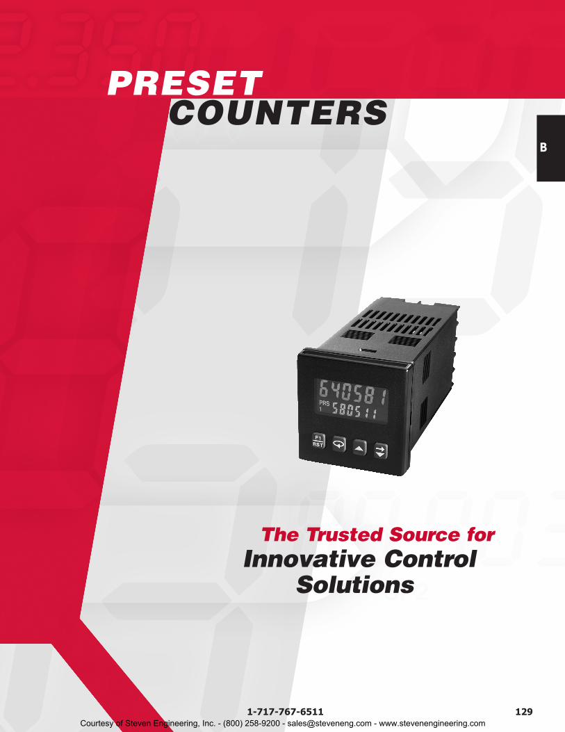
Page 135 Page 136 Page 142 Page 143Page Number
B
130 www.redlion.net
QUICK Specs
8 Digit, .46" (12mm) Reflective,Green and Red Backlight LCD
2 x 6 Digit, Main Display .3"(7mm) Sec. Display .2" (5mm)Reflective and Backlight LCD
6 Digit, .56" (14mm)Red LED
6 Digit, .56" (14mm) StandardGreen or Sunlight Readable Red
LED, Adjustable IntensityDisplay
Counter/Rate Meter 1/16 DIN Counter 1/8 DIN Counter/Rate Meter With Setpoint Capability
1/8 DIN CounterWith Setpoint Capability
Uni-DirectionalUp/DownInhibit
Add/SubtractAdd/Add
QuadratureBatch
Uni-DirectionalUp/DownInhibit
Add/SubtractAdd/Add
QuadratureBatch
Uni-DirectionalUp/DownInhibit
Add/SubtractAdd/Add
QuadratureBatch
Uni-DirectionalUp/DownInhibit
Add/SubtractAdd/Add
QuadratureBatch
20,000 Counts/Sec.Program Dependent
12,000 Counts/Sec.Model and Program Dependent
20,000 Counts/Sec.Program Dependent
34,000 Counts/Sec.34,000 Counts/Sec.Program Dependent
Yes Yes Yes Yes
Front Panel, Remote Front Panel, Remote Front Panel, Remote Front Panel, Remote
NoYes, with Micro Line
Power Supply12 VDC @ 100 mA 24 VDC @ 100 mA, over 50 V
24 VDC @ 50 mA, under 50 V 12 VDC @ 100 mA
Single Form C RelayDual Sinking
Single Form ADual Form A
Current SinkingDual Form C Relays
Dual Form C Quad Form AQuad Sinking Quad Sourcing
RS485 RS485 No No
9 to 28 VDC85 to 250 VAC18 to 36 VDC
24 VAC
50 to 250 VAC21.6 to 250 VDC
85 to 250 VAC11 to 36 VDC
24 VAC
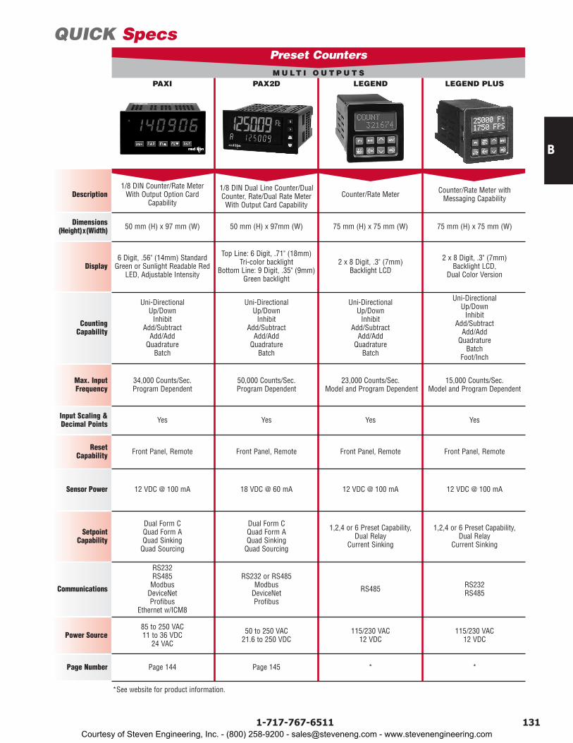
Max. InputFrequency
Input Scaling &Decimal Points
ResetCapability
Sensor Power
SetpointCapability
Power Source
Communications
Counting Capability
Description
CUB5 C48C PAXLCR PAXCD U A L O U T P U T S MU LT I O U T P U T S
Preset Counters
39 mm (H) x 75 mm (W) 50 mm (H) x 50 mm (W) 50 mm (H) x 97mm (W) 50 mm (H) x 97 mm (W)Dimensions(Height)x(Width)
Courtesy of Steven Engineering, Inc. - (800) 258-9200 - [email protected] - www.stevenengineering.com
Page 144 Page 145 * *Page Number
B
1311-717-767-6511
MU LT I O U T P U T S
QUICK Specs
6 Digit, .56" (14mm) StandardGreen or Sunlight Readable Red
LED, Adjustable Intensity
Top Line: 6 Digit, .71" (18mm)Tri-color backlight
Bottom Line: 9 Digit, .35" (9mm)Green backlight
2 x 8 Digit, .3" (7mm)Backlight LCD
2 x 8 Digit, .3" (7mm) Backlight LCD,
Dual Color VersionDisplay
1/8 DIN Counter/Rate Meter With Output Option Card
Capability
1/8 DIN Dual Line Counter/DualCounter, Rate/Dual Rate Meter With Output Card Capability
Counter/Rate Meter Counter/Rate Meter withMessaging Capability
Uni-DirectionalUp/DownInhibit
Add/SubtractAdd/Add
QuadratureBatch
Uni-DirectionalUp/DownInhibit
Add/SubtractAdd/Add
QuadratureBatch
Uni-DirectionalUp/Down Inhibit
Add/Subtract Add/Add
Quadrature Batch
Uni-Directional Up/Down Inhibit
Add/Subtract Add/Add
Quadrature Batch
Foot/Inch
34,000 Counts/Sec.Program Dependent
50,000 Counts/Sec.Program Dependent
23,000 Counts/Sec.Model and Program Dependent
15,000 Counts/Sec. Model and Program Dependent
Yes Yes Yes Yes
Front Panel, Remote Front Panel, Remote Front Panel, Remote Front Panel, Remote
12 VDC @ 100 mA 18 VDC @ 60 mA 12 VDC @ 100 mA 12 VDC @ 100 mA
Dual Form C Quad Form AQuad Sinking Quad Sourcing
Dual Form CQuad Form AQuad SinkingQuad Sourcing
1,2,4 or 6 Preset Capability, Dual Relay
Current Sinking
1,2,4 or 6 Preset Capability, Dual Relay
Current Sinking
RS232RS485ModbusDeviceNetProfibus
Ethernet w/ICM8
RS232 or RS485ModbusDeviceNetProfibus
RS485 RS232RS485
85 to 250 VAC11 to 36 VDC
24 VAC
50 to 250 VAC21.6 to 250 VDC
115/230 VAC 12 VDC
115/230 VAC 12 VDC
50 mm (H) x 97 mm (W) 50 mm (H) x 97mm (W) 75 mm (H) x 75 mm (W) 75 mm (H) x 75 mm (W)
Max. InputFrequency
Input Scaling &Decimal Points
ResetCapability
Sensor Power
SetpointCapability
Power Source
Dimensions(Height)x(Width)
Communications
Counting Capability
Description
PAXI PAX2D LEGEND LEGEND PLUS
Preset Counters
*See website for product information.
Courtesy of Steven Engineering, Inc. - (800) 258-9200 - [email protected] - www.stevenengineering.com
* * * *
B
132 www.redlion.net
QUICK Specs
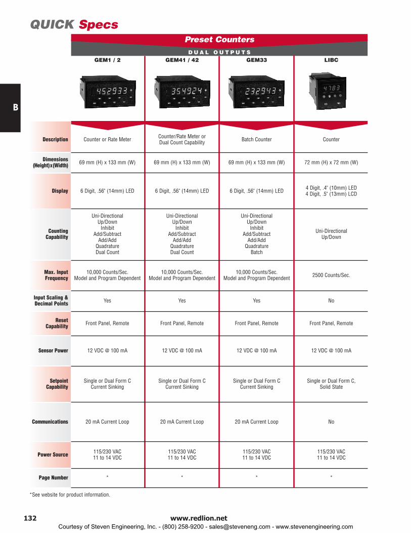
6 Digit, .56" (14mm) LED 6 Digit, .56" (14mm) LED 6 Digit, .56" (14mm) LED 4 Digit, .4" (10mm) LED 4 Digit, .5" (13mm) LCDDisplay
Counter or Rate Meter Counter/Rate Meter or Dual Count Capability Batch Counter Counter
Uni-Directional Up/Down Inhibit
Add/Subtract Add/Add
QuadratureDual Count
Uni-Directional Up/Down Inhibit
Add/Subtract Add/Add
QuadratureDual Count
Uni-Directional Up/Down Inhibit
Add/Subtract Add/Add
Quadrature Batch
Uni-Directional Up/Down
10,000 Counts/Sec. Model and Program Dependent
10,000 Counts/Sec. Model and Program Dependent
10,000 Counts/Sec. Model and Program Dependent 2500 Counts/Sec.
Yes Yes Yes No
Front Panel, Remote Front Panel, Remote Front Panel, Remote Front Panel, Remote
12 VDC @ 100 mA 12 VDC @ 100 mA 12 VDC @ 100 mA 12 VDC @ 100 mA
Single or Dual Form C Current Sinking
Single or Dual Form C Current Sinking
Single or Dual Form C Current Sinking
Single or Dual Form C, Solid State
20 mA Current Loop 20 mA Current Loop 20 mA Current Loop No
115/230 VAC11 to 14 VDC
115/230 VAC11 to 14 VDC
115/230 VAC11 to 14 VDC
115/230 VAC11 to 14 VDC
69 mm (H) x 133 mm (W) 69 mm (H) x 133 mm (W) 69 mm (H) x 133 mm (W) 72 mm (H) x 72 mm (W)
Max. InputFrequency
Input Scaling &Decimal Points
ResetCapability
Sensor Power
SetpointCapability
Power Source
Dimensions(Height)x(Width)
Communications
Counting Capability
Description
GEM1 / 2 GEM41 / 42 GEM33 LIBCD U A L O U T P U T S
Preset Counters
Page Number
*See website for product information.
Courtesy of Steven Engineering, Inc. - (800) 258-9200 - [email protected] - www.stevenengineering.com
B
1331-717-767-6511
PAXLCR
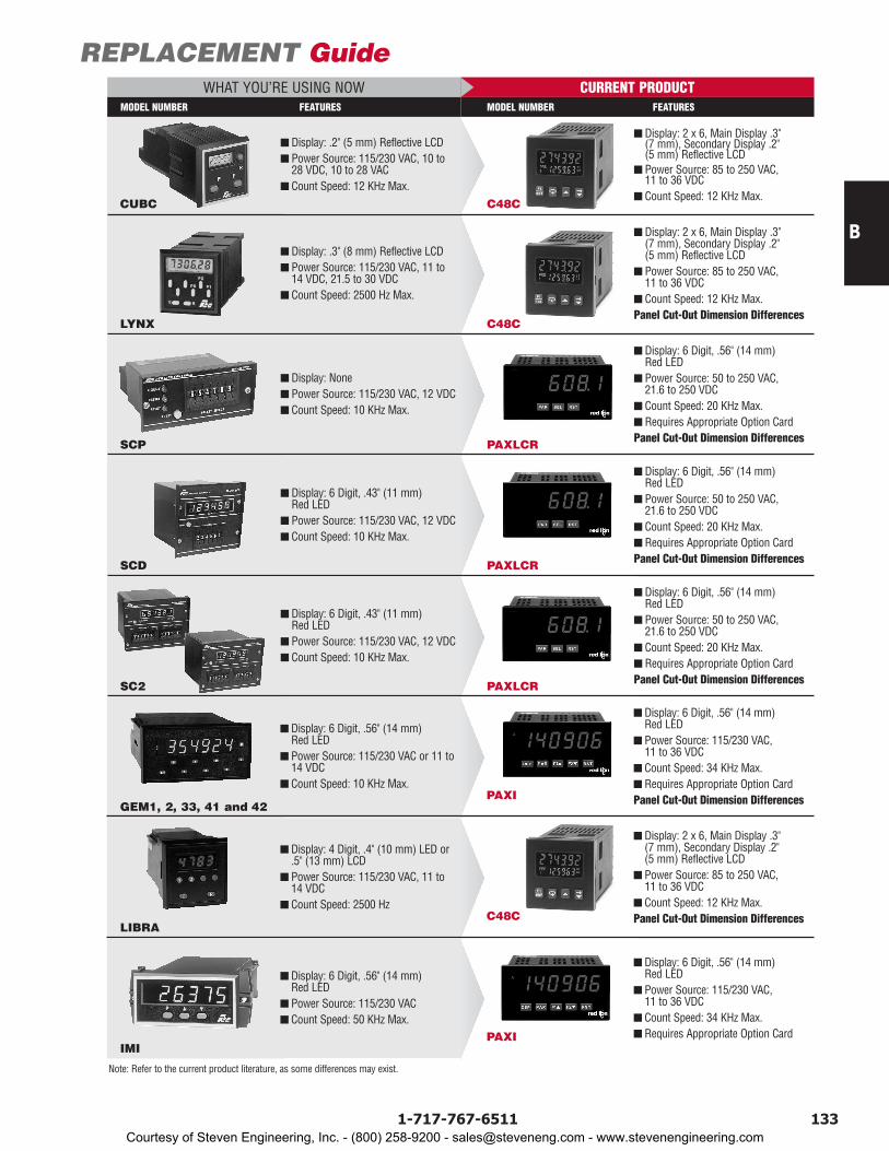
REPLACEMENT GuideWHAT YOU’RE USING NOW CURRENT PRODUCT
C48CCUBC
n Display: 2 x 6, Main Display .3"(7 mm), Secondary Display .2"(5 mm) Reflective LCD
n Power Source: 85 to 250 VAC,11 to 36 VDC
n Count Speed: 12 KHz Max.
n Display: .2" (5 mm) Reflective LCDn Power Source: 115/230 VAC, 10 to
28 VDC, 10 to 28 VACn Count Speed: 12 KHz Max.
C48CLYNX
n Display: 2 x 6, Main Display .3"(7 mm), Secondary Display .2"(5 mm) Reflective LCD
n Power Source: 85 to 250 VAC,11 to 36 VDC
n Count Speed: 12 KHz Max.Panel Cut-Out Dimension Differences
n Display: .3" (8 mm) Reflective LCDn Power Source: 115/230 VAC, 11 to
14 VDC, 21.5 to 30 VDCn Count Speed: 2500 Hz Max.
MODEL NUMBER FEATURES MODEL NUMBER FEATURES
Note: Refer to the current product literature, as some differences may exist.
SCP
n Display: 6 Digit, .56" (14 mm)Red LED
n Power Source: 50 to 250 VAC,21.6 to 250 VDC
n Count Speed: 20 KHz Max.n Requires Appropriate Option CardPanel Cut-Out Dimension Differences
n Display: Nonen Power Source: 115/230 VAC, 12 VDCn Count Speed: 10 KHz Max.
PAXLCRSCD
n Display: 6 Digit, .56" (14 mm)Red LED
n Power Source: 50 to 250 VAC,21.6 to 250 VDC
n Count Speed: 20 KHz Max.n Requires Appropriate Option CardPanel Cut-Out Dimension Differences
n Display: 6 Digit, .43" (11 mm)Red LED
n Power Source: 115/230 VAC, 12 VDCn Count Speed: 10 KHz Max.
PAXLCRSC2
n Display: 6 Digit, .56" (14 mm)Red LED
n Power Source: 50 to 250 VAC,21.6 to 250 VDC
n Count Speed: 20 KHz Max.n Requires Appropriate Option CardPanel Cut-Out Dimension Differences
n Display: 6 Digit, .43" (11 mm)Red LED
n Power Source: 115/230 VAC, 12 VDCn Count Speed: 10 KHz Max.
PAXIGEM1, 2, 33, 41 and 42
n Display: 6 Digit, .56" (14 mm)Red LED
n Power Source: 115/230 VAC,11 to 36 VDC
n Count Speed: 34 KHz Max.n Requires Appropriate Option CardPanel Cut-Out Dimension Differences
n Display: 6 Digit, .56" (14 mm)Red LED
n Power Source: 115/230 VAC or 11 to14 VDC
n Count Speed: 10 KHz Max.
C48CLIBRA
n Display: 2 x 6, Main Display .3"(7 mm), Secondary Display .2"(5 mm) Reflective LCD
n Power Source: 85 to 250 VAC,11 to 36 VDC
n Count Speed: 12 KHz Max.Panel Cut-Out Dimension Differences
n Display: 4 Digit, .4" (10 mm) LED or.5" (13 mm) LCD
n Power Source: 115/230 VAC, 11 to14 VDC
n Count Speed: 2500 Hz
PAXIIMI
n Display: 6 Digit, .56" (14 mm)Red LED
n Power Source: 115/230 VAC,11 to 36 VDC
n Count Speed: 34 KHz Max.n Requires Appropriate Option Card
n Display: 6 Digit, .56" (14 mm)Red LED
n Power Source: 115/230 VACn Count Speed: 50 KHz Max.
Courtesy of Steven Engineering, Inc. - (800) 258-9200 - [email protected] - www.stevenengineering.com

B
134 www.redlion.net
This page intentionally left blank.
Courtesy of Steven Engineering, Inc. - (800) 258-9200 - [email protected] - www.stevenengineering.com
B
1351-717-767-6511
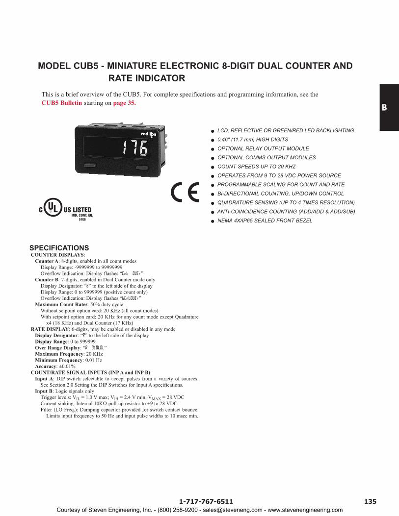
MODEL CUB5 - MINIATURE ELECTRONIC 8-DIGIT DUAL COUNTER AND RATE INDICATOR
This is a brief overview of the CUB5. For complete specifications and programming information, see the CUB5 Bulletin starting on page 35.
LCD, REFLECTIVE OR GREEN/RED LED BACKLIGHTING
0.46" (11.7 mm) HIGH DIGITS
OPTIONAL RELAY OUTPUT MODULE
OPTIONAL COMMS OUTPUT MODULES
COUNT SPEEDS UP TO 20 KHZ
OPERATES FROM 9 TO 28 VDC POWER SOURCE
PROGRAMMABLE SCALING FOR COUNT AND RATE
BI-DIRECTIONAL COUNTING, UP/DOWN CONTROL
QUADRATURE SENSING (UP TO 4 TIMES RESOLUTION)
ANTI-COINCIDENCE COUNTING (ADD/ADD & ADD/SUB)
NEMA 4X/IP65 SEALED FRONT BEZEL
SPECIFICATIONS COUNTER DISPLAYS:
Counter A: 8-digits, enabled in all count modesDisplay Range: -9999999 to 99999999Overflow Indication: Display flashes “Cnt OVEr”
Counter B: 7-digits, enabled in Dual Counter mode onlyDisplay Designator: “b” to the left side of the displayDisplay Range: 0 to 9999999 (positive count only)Overflow Indication: Display flashes “bCntOVEr”
Maximum Count Rates: 50% duty cycleWithout setpoint option card: 20 KHz (all count modes)With setpoint option card: 20 KHz for any count mode except Quadrature
x4 (18 KHz) and Dual Counter (17 KHz) RATE DISPLAY: 6-digits, may be enabled or disabled in any mode
Display Designator: “R” to the left side of the displayDisplay Range: 0 to 999999Over Range Display: “R OLOLOL”Maximum Frequency: 20 KHzMinimum Frequency: 0.01 HzAccuracy: ±0.01%
COUNT/RATE SIGNAL INPUTS (INP A and INP B):Input A: DIP switch selectable to accept pulses from a variety of sources.
See Section 2.0 Setting the DIP Switches for Input A specifications. Input B: Logic signals only
Trigger levels: VIL = 1.0 V max; VIH = 2.4 V min; VMAX = 28 VDCCurrent sinking: Internal 10KΩ pull-up resistor to +9 to 28 VDCFilter (LO Freq.): Damping capacitor provided for switch contact bounce.
Limits input frequency to 50 Hz and input pulse widths to 10 msec min.
C US LISTEDULR
51EBIND. CONT. EQ.
Courtesy of Steven Engineering, Inc. - (800) 258-9200 - [email protected] - www.stevenengineering.com

B
136 www.redlion.net
LCD, 7 SEGMENT, 2 LINE, 6 DIGIT DISPLAY, POSITIVE REFLECTIVE OR NEGATIVE TRANSMISSIVE MODELS WITH RED TOP LINE AND GREEN BOTTOM LINE BACKLIGHTING
QUADRATURE SENSING ( Up to 4 times resolution) BI-DIRECTIONAL COUNTING, UP/DOWN CONTROL FIELD REPLACEABLE RELAY OUTPUT BOARDS STATUS INDICATORS FOR OUTPUTS NEMA 4X/IP65 SEALED BEZEL PARAMETER SECURITY VIA PROGRAMMABLE OPERATOR
ACCESS PRIVILEGES AND PROTECTED VALUE MENU PROGRAMMABLE USER INPUTS AND FRONT PANEL
FUNCTION KEY
HORIZONTAL OR VERTICAL STACKING OF MULTIPLE UNITS 85 to 250 VAC OR 18 to 36 VDC/24 VAC POWERED UNITS RS485 SERIAL COMMUNICATIONS OPTION CHOICE OF NUMERIC DATA ENTRY MODES
DESCRIPTIONThe Model C48 Counter is available as a Standard Counter or a Batch
Counter. The Standard Counter is available with single or dual presets. The Batch Counter has a main process counter with dual presets and a secondary counter with a single preset. The secondary counter can be selected to function as a batch or a total counter.
The C48C features a 7 segment, 2 line by 6 digit reflective or backlit LCD display. For the backlit versions, the main display line is red and shows the count value or the Batch/Total value when preset 3 or output 3 is viewed in the secondary display. The smaller secondary display line is green and can be used to view the prescaler value, preset values, output time values or Batch/Total count values (Batch model).
The C48C offers a choice of nine programmable counting modes for use in applications requiring bi-directional, anti-coincidence, and quadrature counting. The unit may be programmed to register counts on both edges of the input signal providing frequency doubling capability. DIP switches are used for input configuration set-up and to provide a Program Disable function.
Four front panel push-buttons are used for programming the operating modes and data values, changing the viewed display, and performing user programmable functions, e.g. reset, etc. The C48C can be configured for one of two numeric data entry methods, digit entry or automatic scrolling. The digit entry method allows for the selection and incrementing of digits individually. The automatic scrolling method allows for the progressive change of one through all digit positions by pressing and holding the “up” or “down” button.
The Program Disable DIP switch, a user-programmable code value, and an external user input selected for Program Disable can be utilized to provide multi-level protection against unauthorized changes to data values and unit configuration.
The C48 Counter has programmable User Inputs and a programmable front panel function key. The user inputs can be configured as sinking (active low) or sourcing (active high) inputs via a single plug jumper. The user inputs and the front panel function key can be configured to provide a variety of functions.
The Standard Counter with Dual Presets is available with solid-state or Relay outputs. The Single Preset model has a solid-state and relay output. The Batch Counter has relay outputs for Output 2 and the Batch/Total Output 3, with Output 1 available as solid-state. The Batch Counter is also available with three solid-state outputs. For all C48 Counters, the solid-state outputs are available in a choice of NPN current sinking or PNP current sourcing, open-collector transistor outputs. All relay output boards are field replaceable.
A Prescaler Output model is available as a Dual Preset, with solid-state outputs. The Prescaler Output is useful for providing a lower frequency scaled pulse train to a PLC or another external totalizing counter. The Prescaler Output provides a programmable width output pulse for every count or every 10 counts registered on the display.
The optional RS-485 serial communication interface provides two-way communication between a C48 and other compatible equipment such as a printer, PLC, HMI, or a host computer. In multipoint applications (up to thirty-two), the address number of each C48 on the line can be programmed from 0 to 99. Data from the C48 can be interrogated or changed, and alarm output(s) may be reset by sending the proper command code via serial communications. PC software, SFC48, allows for easy configuration of controller parameters. These settings can be saved to disk for later use or used for multi-controller down loading. On-line help is provided within the software.
Optional programming software (SFC48) is available to program all unit configuration parameters. The software allows unit configurations to be created, uploaded, downloaded, and saved to a file for later use or multi-unit programming.
The unit is constructed of a lightweight, high impact plastic case with a textured front panel and a clear display window. The front panel meets NEMA 4X/IP65 specifications when properly installed. Multiple units can be stacked horizontally or vertically. Modern surface-mount technology, extensive testing, plus high immunity to noise interference makes the C48 Counters extremely reliable in industrial environments.
C48C SERIES - 1/16 DIN COUNTERSMODEL C48CS - SINGLE PRESETMODEL C48CD - DUAL PRESETMODEL C48CB - THREE PRESET BATCH
13 14
121110
9
8
7
6
5
4
3
2
1
(49.5)
(49.5)1.95
1.95
4.17 (105.9)0.37(9.4)
(44.7)1.76
1.76 (44.7) 1.772
(45 )1.772
(45 )
+0.024-0.000
+0.6-0.0
+0.024-0.000
+0.6-0.0
F1RST
21 3SRP
302010
DIMENSIONS In inches (mm) PANEL CUT-OUT
UL Recognized Component, File # E137808
Courtesy of Steven Engineering, Inc. - (800) 258-9200 - [email protected] - www.stevenengineering.com
B
1371-717-767-6511
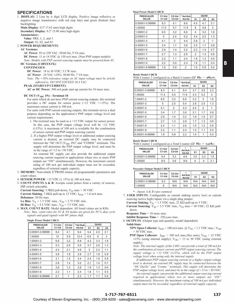
SPECIFICATIONS1. DISPLAY: 2 Line by 6 digit LCD display. Positive image reflective or
negative image transmissive with red (top line) and green (bottom line) backlightingMain Display: 0.3" (7.62 mm) high digits Secondary Display: 0.2" (5.08 mm) high digitsAnnunciators:
Value: PRS, 1, 2, and 3Output: 01, 02, and 03.
2. POWER REQUIREMENTS:AC Versions:
AC Power: 85 to 250 VAC, 50/60 Hz, 9 VA max.DC Power: 11 to 14 VDC @ 150 mA max. (Non PNP output models)Note: Models with PNP current sourcing outputs must be powered from AC.
DC Versions (C48XXX1X):CONTINUOUS:
DC Power: 18 to 36 VDC; 5.5 W max.AC Power: 24 VAC ±10%; 50/60 Hz; 7 VA max.Note: The +10% tolerance range on AC input voltage must be strictly
adhered to. DO NOT EXCEED 26.4 VAC.PEAK (START-UP CURRENT):
AC or DC Power: 500 mA peak start-up current for 10 msec max.
DC OUT (VSRC IN) - Terminal 10For units which do not have PNP current sourcing outputs, this terminal provides a DC output for sensor power (+12 VDC +/-15%). The maximum sensor current is 100 mA.For units with PNP current sourcing outputs, this terminal serves a dual purpose depending on the application’s PNP output voltage level and current requirements. 1. The terminal may be used as a +12 VDC output for sensor power.
In this case, the PNP output voltage level will be +12 VDC (±15%). A maximum of 100 mA is available for the combination of sensor current and PNP output sourcing current.
2. If a higher PNP output voltage level or additional output sourcing current is desired, an external DC supply may be connected between the “DC OUT (VSRC IN)” and “COMM.” terminals. This supply will determine the PNP output voltage level, and must be in the range of +13 to +30 VDC. An external DC supply can also provide the additional output sourcing current required in applications where two or more PNP outputs are “ON” simultaneously. However, the maximum current rating of 100 mA per individual output must not be exceeded, regardless of external supply capacity.
3. MEMORY: Nonvolatile E2PROM retains all programmable parameters and count values.
4. SENSOR POWER: +12 VDC (± 15%) @ 100 mA max.5. COUNT INPUTS A & B: Accepts count pulses from a variety of sources,
DIP switch selectable.Current Sourcing: 3.9KΩ pull-down, VIN max = 30 VDCCurrent Sinking: 7.8KΩ pull-up to 12 VDC; ISNK = 1.8 mA max.Debounce: 50 Hz max.Lo Bias: VIL = 1.5 VDC max., VIH = 3.75 VDC min.Hi Bias: VIL = 5.5 VDC max., VIH = 7.5 VDC min.
6. MAX. COUNT RATE: Model dependent. All listed values are in KHz.Note: Max. count rates for X2 & X4 modes are given for 50 % duty cycle
signals and quad signals with 90° phase shift.Single Preset Model C48CS
Dual Preset Model C48CD
Batch Model C48CBWith Counter 2 configured as a Batch Counter ( = )
Batch Model C48CBWith Counter 2 configured as a Total Counter ( = )
Prescaler Output Model C48CP
* - Inputs A & B rates summed.7. USER INPUTS: Configurable as current sinking (active low) or current
sourcing (active high) inputs via a single plug jumper.Current Sinking: VIL = 1.5 VDC max, 22 KΩ pull-up to 5 VDC.Current Sourcing: VIH = 3.5 VDC min., VIN max = 30 VDC; 22 KΩ pull-
down.Response Time = 10 msec max.Inhibit Response Time = 250 µsec max.
8. OUTPUTS: (Output type and quantity, model dependent)Solid-State:
NPN Open Collector: ISNK = 100 mA max. @ VOL = 1.1 VDC max.; VOH = 30 VDC max.
PNP Open Collector: ISRC = 100 mA max.(See note); VOH = 12 VDC ±15% (using internal supply); VOH = 13 to 30 VDC (using external supply).Note: The internal supply of the C48C can provide a total of 100 mA for the combination of sensor current and PNP output sourcing current. The supply voltage is +12 VDC (±15%), which will be the PNP output voltage level when using only the internal supply.
If additional PNP output sourcing current or a higher output voltage level is desired, an external DC supply may be connected between the “DC Out/In” and “Comm.” terminals. This supply will determine the PNP output voltage level, and must be in the range of +13 to +30 VDC.
An external supply can provide the additional output sourcing current required in applications where two or more outputs are “ON” simultaneously. However, the maximum rating of 100 mA per individual output must not be exceeded, regardless of external supply capacity.
N/AN/AN/AN/AN/A81.00000N/AN/AN/AN/AN/A6.20.00001-0.99999X4X2X1
QUAD*Ad-Sub Ad-Ad
C2-Usr C2-Ud
C1-Usr C1-Ud
PRESCALER VALUE
2.1448.63.68.51.000001.63.33.56.63.36.50.00001-0.99999X4X2X1
QUAD*Ad-Sub Ad-Ad
C2-Usr C2-Ud
C1-Usr C1-Ud
PRESCALER VALUE
0.411.42.20.91.99.00001-9.999990.51.11.52.41.12.28.00001-90.61.21.62.61.12.47.00001-80.61.31.72.81.32.76.00001-70.71.51.93.21.42.95.00001-60.81.72.13.81.73.44.00001-5122.44.224.13.00001-4
1.32.52.85.42.552.00001-31.633.2
3.7
6.63.26.51.00001-234.24.311.85.511.41.00000
2.23.68.44.18.30.00001-0.99999X4X2X1
QUAD*Ad-Sub Ad-Ad
C2-Usr C2-Ud
C1-Usr C1-Ud
PRESCALER VALUE
0.40.91.520.91.99.00001-9.999990.51.11.62.30.92.28.00001-90.61.21.82.41.12.27.00001-80.61.322.81.32.76.00001-70.71.42.23.21.42.95.00001-60.81.72.53.81.73.44.00001-5122.84.424.13.00001-4
1.32.53.45.22.452.00001-31.63.246.63.26.51.00001-235.8611.55.711.51.00000
2.14.14.58.64.18.30.00001-0.99999X4X2X1
QUAD*Ad-Sub Ad-Ad
C2-Usr C2-Ud
C1-Usr C1-Ud
PRESCALER VALUE
PRESCALER VALUE
C1-Usr C1-Ud
C2-Usr C2-Ud
*Ad-Sub Ad-Ad
QUADX1 X2 X4
0.00001-0.99999 8.4 4.1 9.4 5.4 4.5 2.1
1.00000 12 5.9 12.4 6.5 6 31.00001-2 6.6 3.2 6.8 4.3 3.3 1.62.00001-3 5.3 2.6 5.6 3.7 2.6 1.33.00001-4 4.3 2.1 4.6 3 2.2 1.14.00001-5 3.6 1.8 3.8 2.7 1.8 0.95.00001-6 3.1 1.5 3.4 2.4 1.6 0.86.00001-7 2.8 1.4 3.2 2.1 1.4 0.77.00001-8 2.6 1.3 2.8 1.9 1.3 0.68.00001-9 2.3 1.1 2.4 1.8 1.1 0.59.00001-9.99999 2.1 1 2.3 1.7 1.1 0.5
Courtesy of Steven Engineering, Inc. - (800) 258-9200 - [email protected] - www.stevenengineering.com
B
138 www.redlion.net
8. OUTPUTS: (Output type and quantity, model dependent) Cont’dRelay: Form A contact, Rating = 5 A @ 250 VAC, 30 VDC (resistive load),
1/10 HP @ 120 VAC (inductive load)Relay Life Expectancy: 100,000 cycles min. at max. load rating
Programmable Timed Output: User selectable output time resolution.0.01 Second Resolution: 0.01 to 99.99 sec, ± 0.01% +20 msec max.
(Prescalers less than 2)0.1 Second Resolution: 0.1 to 999.9 sec, ± 0.01% + 100 msec (Prescalers
less than 2)Note: For Prescaler values above 2, the timed delay output is affected by
the count speed (rate).9. RS485 SERIAL COMMUNICATIONS (Optional): Up to 32 units can be
connected.Baud Rate: Programmable from 1200 to 9600 baudAddress: Programmable from 0 to 99Data Format: 10 Bit Frame, 1 start bit, 7 or 8 data bits, 1 or No Parity bit,
and 1 stop bitParity: Programmable for Odd (7 data bits), Even (7 data bits), or None (8
data bits)10. CERTIFICATIONS AND COMPLIANCES:
UL Recognized Component, File #E137808 Recognized to U.S. and Canadian requirements under the Component Recognition Program of Underwriters Laboratories, Inc.
ELECTROMAGNETIC COMPATIBILITY
Notes:AC VERSIONS1. A power line filter, RLC#LFIL0000 or equivalent, was installed when the
unit was DC powered.DC VERSIONS
To insure compliance with the EMC standards listed above, do not connect any wires from the terminal(s) labeled “COMM.” to the “DC-” supply terminal (12), when powering the unit from a DC supply.
Refer to EMC Installation Guidelines section of the manual for additional information.
11. ENVIRONMENTAL CONDITIONS:Operating Temperature: 0°C to 50°CStorage Temperature: -40°C to 70°COperating and Storage Humidity: 85% max. relative humidity(non-condensing) from 0°C to 50°C.Altitude: Up to 2000 meters
12. ELECTRICAL CONNECTIONS: Wire clamping screw terminals.13. CONSTRUCTION: Black plastic case with collar style panel latch. The
panel latch can be installed for horizontal or vertical stacking. Black plastic textured bezel with clear display viewing window. Unit assembly with circuit boards can be removed from the case without removing the case from the panel or disconnecting the wiring. Front panel meets NEMA 4X/IP65 requirements for indoor use, when properly installed. Installation Category II, Pollution Degree 2.
14. WEIGHT: 6.0 oz (170 g)
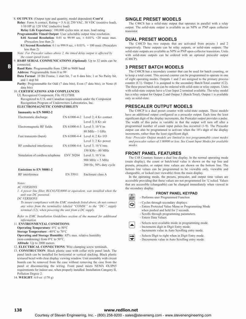
SINGLE PRESET MODELSThe C48CS has a solid-state output that operates in parallel with a relay
output. The solid-state output is available as an NPN or PNP open collector transistor.
DUAL PRESET MODELSThe C48CD has two outputs that are activated from presets 1 and 2
respectively. These outputs can be relay outputs, or solid-state outputs. The solid-state outputs are available as NPN or PNP open-collector transistors. Units with solid-state outputs can be ordered with an optional prescaler output (C48CP).
3 PRESET BATCH MODELSThe C48CB has a secondary counter that can be used for batch counting, or
to keep a total count. This second counter can be programmed to operate in one of eight operating modes. Outputs 1 and 2 are assigned to the primary process counter (C1). Output 3 is assigned to the secondary Batch/Total counter (C2). The three preset batch unit can be ordered with solid-state or relay outputs. Units with solid-state outputs have a User Input 2 terminal available. The relay model has a relay output for Output 2 and Output 3 (Batch/Total). Output 1 is available only as solid-state.
PRESCALER OUTPUT MODELSThe C48CP is a dual preset counter with solid-state outputs. These models
have an additional output configured as a prescaler output. Each time the least significant digit of the display increments, the Prescaler output provides a pulse. The width of this pulse is variable in that the output will turn off after a programmed number of count input pulses has occurred (1-9). The Prescaler output can also be programmed to activate when the 10’s digit of the display increments, rather than the least significant digit.Note: Prescaler Output models are limited to two programmable count modes
and prescaler values of 1.00000 or less. See Count Input Modes for available modes.
FRONT PANEL FEATURESThe C48 Counters feature a dual line display. In the normal operating mode
(main display), the count or batch/total value is shown on the top line and presets, prescaler, or output time values are shown on the bottom line. The bottom line values can be programmed to be viewable only, viewable and changeable, or locked (not viewable) from the main display.
In the operating mode, the presets, prescaler, and output time values are accessible providing that these values are not programmed for ‘L’ocked. Values that are accessible (changeable) can be changed immediately when viewed in the secondary display.
FRONT PANEL KEYPAD - Performs user Programmed Function - Cycles through secondary displays. - Enters Protected Value Menu or Programming Mode
when pushed and held for 2 seconds. - Scrolls through programming parameters. - Enters Data Values.
- Selects next available mode in programming mode. - Increments digit in Digit Entry mode. - Increments value in Auto Scrolling entry mode. - Selects Digit to right when in Digit Entry mode. - Decrements value in Auto Scrolling entry mode.
Enclosure class AEN 55011RF interferenceEmissions to EN 50081-2
Level 3; 10 V/mENV 50204Simulation of cordless telephone150 KHz - 80 MHzLevel 3; 10 V/rms EN 61000-4-6RF conducted interferenceLevel 3; 2 Kv powerLevel 4; 2 Kv I/OEN 61000-4-4Fast transients (burst)80 MHz - 1 GHzLevel 3; 10 V/m EN 61000-4-3Electromagnetic RF fieldsLevel 3; 8 Kv airLevel 2; 4 Kv contactEN 61000-4-2Electrostatic discharge
200 Hz, 50% duty cycle
Immunity to EN 50082-2
900 MHz ± 5 MHz
Courtesy of Steven Engineering, Inc. - (800) 258-9200 - [email protected] - www.stevenengineering.com

B
1391-717-767-6511
USER INTERFACE/PROGRAMMING MODESThe operating modes of the C48C are programmed using the front panel
keypad. To enter the programming menu, the key is pushed and held for 2 seconds. Within the programming menu, the key is used to sequence through the list of programming parameters.
PROGRAMMING MENU
Program Security/Operator Accessible ValuesThe Program Disable DIP switch, programmable code value, User Input
(programmed for Program Disable), and the Accessible Value parameters provide various levels of security against unauthorized programming changes. The accessible values parameters provide individual access or locking of each value.
Protected Value MenuThe Protected Value Menu allows access to selected presets, prescaler and
timed output values without having them viewable or changeable from the main display. To enter the protected menu, the key is pressed and held, and a programmed code value is entered.
Programming Numeric Data ValuesThe Presets may be accessible when the unit is in its operating mode. Pressing
the key will sequence the secondary display through the available preset, prescaler and Batch/Total count values.
To change a data value it must be visible on the secondary display. Pressing the or key will allow changing of the value. If the data entry method has been set to “digit entry”, pressing the key multiple times will select other digits. Pressing the key will increment the selected digit. If the data entry method is set to “Auto scrolling”, the data value can be changed by pressing and holding the or keys to change one or all digits of the display.The data value will be entered when the key is pushed, or the old value will be retained if no key activity is detected for 10 seconds.
Count Input Modes - This parameter controls the count/control function of Inputs A and B. It also
allows Input B to be used as a User Input with the same programmable functions as the dedicated User Inputs.
* These are the only count input modes available on the Prescaler Output Model.
Programmable Operating Modes - These modes determine the operational characteristics of the counter. In the
tables, 01, 02, and 03, refer to Outputs 1,2, and 3 respectively.
1 - Manual Reset to Zero, Latched Output
2 - Manual Reset to Zero, Timed Output
3 - Manual Reset to Preset, Latched Output
4 - Manual Reset to Preset, Timed Output
5 - Auto Reset to Zero, Timed Output
6 - Auto Reset to Preset, Timed Output
7 - Auto Reset to Zero at Timed Output End
8 - Auto Reset to Preset at Timed Output End
SINGLE PRESET OPERATING MODES
Auto Reset to Preset 3 at 03 Timed Output End-8Auto Reset to Preset 3, 03 Timed-7Auto Reset to Zero at 03 Timed Output End-6Auto Reset to Zero, 03 Timed-5Manual Reset to Preset 3, 03 Timed
COUNTER 2 OPERATING MODES (C48CB Only)
-4Manual Reset to Preset 3, 03 Latched-3Manual Reset to Zero, 03 Timed-2Manual Reset to Zero, 03 Latched-1
Auto Reset to Preset 2 at 02 End, 01 off at 02, 02 Timed
Auto Reset to Zero at 02 End, 01 off at 02, 02 Timed
Manual Reset to Preset 2, 01 and 02 Timed
-
-
-
18
16
8
Auto Reset to Preset 2 at 02 End, 01 and 02 Timed
Auto Reset to Zero at 02 End, 01 and 02 Timed
Manual Reset to Preset 2, 01 Timed, 02 Latched
-
-
-
17
15
7
Auto Reset to Preset 2, 01 off at 02, 02 Timed
Manual Reset to Preset 2, Latched Outputs
-
-
14
6
Auto Reset to Preset 2, 01 and 02 Timed
Manual Reset to Zero, 01 off at 02, 02 Timed
-
-
13
5
Auto Reset to Zero, 01 off at 02, 02 Timed
Manual Reset to Zero, 01 off at 02, 02 Latched
-
-
12
4
Auto Reset to Zero, 01 and 02 Timed
Manual Reset to Zero, 01 and 02 Timed
-
-
11
3
Manual Reset to Preset 2, 01 off at 02, 02 Timed
Manual Reset to Zero, 01 Timed, 02 Latched
-
-
10
2
Manual Reset to Preset 2, 01 off at 02, 02 Latched
Manual Reset to Zero, Latched Outputs
-
-
9
1
DUAL PRESET AND BATCH COUNTER 1 OPERATING MODES
MODE INPUT A INPUT B
Count User Input * Count (X2) User Input Count Up/Dn Control * Count (X2) Up/Dn Control Add Count Subtract Count Add Count Add Count Quad X1 Inputs Quad X2 Inputs Quad X4 Inputs
- Accessibility of Prescaler Value
- Prescaler Value
- Decimal Point Position
- Count Input Modes
- Counter 1 Operating Mode
- Counter 2 Assignment (C48CB only)
- Counter 2 Operating Mode (C48CB only)
- Accessibility of Preset Values
- Preset 1, 2, and 3 Values
- P1 Track P2 (not available on C48CS)
- Accessibility of Output Time Values
- Output 1, 2, and 3 Time Values
- Reverse Output Annunciator Logic - Reverse Output/Relay Logic
- Power Up Output State
- User Input 1
- User Input 2 (Not available on Batch Relay Models)
- User Input b
- User F1 Key
- Programming/Protected Parameter menu Code
- Scroll Display
- Serial Baud Rate & Parity Settings
- Serial Unit Address
- Abbreviate Serial Mnemonics
- Print Options
- Print & Reset Count Value
- Prescaler Output Pulse (C48CP only)
- Prescaler Output Pulse Length width (C48CP only)
- Load Factory Default Settings
- Output Resolution
- Digit or Auto Scrolling Data Entry Mode
(RS485 option only)
Courtesy of Steven Engineering, Inc. - (800) 258-9200 - [email protected] - www.stevenengineering.com

B
140 www.redlion.net
SLOW DOWN & CUT TO LENGTH WITH TOTAL FOOTAGETo improve production efficiency, a wallpaper manufacturing plant is
installing cut to length counters on the roll form machines. Currently, electro-mechanical counters are used for length measurements. The operator slows the machine down upon arriving at the desired length, stops and then cuts. The addition of the C48CB batch counters eliminates the operator’s manual observation and control.
The operator programs the required cut length as Preset 2. Preset 1 is preprogrammed for tracking and will automatically follow Preset 2. Preset 1 is used as the slow down, and is set for a value 0.25 yards less than Preset 2. The process count is programmed to automatically reset at the Preset 2 cut length of 11.00 yards, and begin counting for the next roll. Counter 2 is programmed as a totalizer and is recorded and reset (via key switch) at the end of the operator’s shift. The C48CB was ordered with the RS-485 serial communication option. Future plans include a data acquisition program to interrogate the C48CB’s. A 100 ppr rotary pulse generator is shaft coupled to a 4" pinch roller for length measurement. Display units desired is 0.01 yards. Program Security features are set to allow access to Preset 2 only. This allows the operator to change the required cut length, but prevents acidental changes to other programming parameters that may adversely affect process operation. After all programming is complete, the Program Disable DIP switch is moved to the up position to enable the Program Security function.
Circumference Of Pinch Roller:circumference = π × diameter
12.56636 = 3.14159 × 4.00
Pulses Per Yard:
36 inches x 1 rev = 2.8647913 rev/yard 1 yard 12.56636"
2.8647913 rev/yard × 100 ppr/rev = 286.47913 pulses/yard
Prescaler:
Prescaler = Display units number of pulses
= 100 286.47913
Prescaler = 0.34907
Products:C48CB108RPGQ0100
PROGRAMMING
(locked)
PRS1 (value 0.25 less than PRS2 for slowdown) PRS2 (cut length) PRS3 (Set high so output does not activate)
1 2 3
MULTIPLE UNIT STACKINGThe C48C is designed for close spacing of multiple units. Units can be
stacked either horizontally or vertically. For vertical stacking, install the panel latch with the screws to the sides of the unit. For horizontal stacking, the panel latch screws should be at the top and bottom of the unit. The minimum spacing
from center line to center line of the units is 1.96" (49.8 mm). This spacing is the same for vertical or horizontal stacking.Note: When stacking units, provide adequate panel ventilation to ensure that
the maximum operating temperature range is not exceeded.
2.39 (60.7)
1.96 (49.8)MAX
MAX
2.39 (60.7)MAX.
1.96 (49.8)MAX.
1.96 (49.8)MIN
STANDARDPANEL
CUT-OUT
IF NEMA 4 IS NOT REQUIRED,THIS PANEL MATERIAL MAY BE REMOVED.
PANEL CUT-OUT SPACING FOR MULTIPLE UNIT STACKING. HORIZONTAL ARRANGEMENT SHOWN.
PANEL LATCH INSTALLED FOR VERTICAL UNIT STACKING
PANEL LATCH INSTALLED FOR HORIZONTAL UNIT STACKING
01-SS 12+
~AC
14A(+)
RS-485 OPTION
4 +5
AC~11+
1 13
3 +2
+
B(-)
910
6
87
+ USER INPUT 1
INPUT A
INPUT/USER B
COMM.
DC OUT/IN
+
+
++
++++
03-RLY
03-RLY
02-RLY
02-RLY
ACPOWER KEY
SWITCH
TO CUT
TO SLOW DOWN
SHIELD
Courtesy of Steven Engineering, Inc. - (800) 258-9200 - [email protected] - www.stevenengineering.com
B
1411-717-767-6511
C48CP
ACCESSORIES
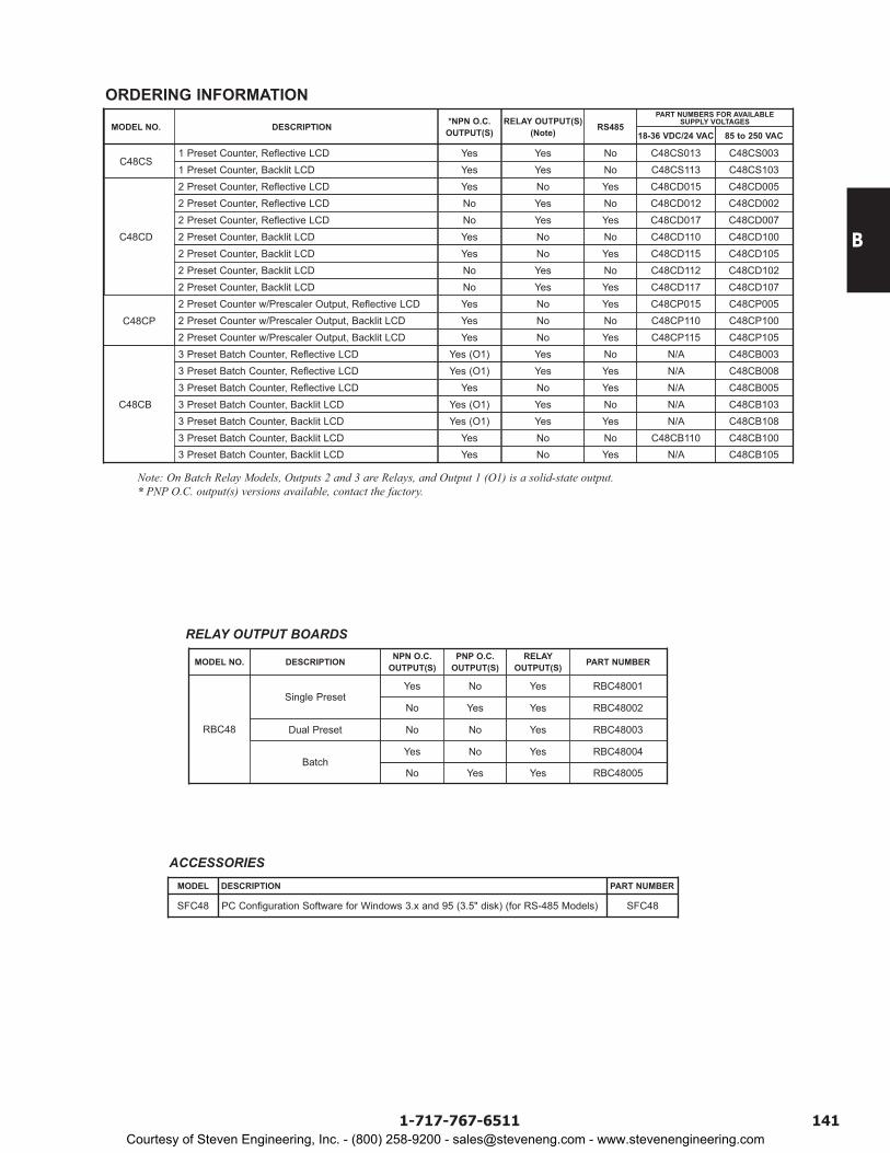
MODEL NO. DESCRIPTION RS48585 to 250 VAC18-36 VDC/24 VAC
C48CS1 Preset Counter, Reflective LCD Yes Yes No C48CS003C48CS0131 Preset Counter, Backlit LCD Yes Yes No C48CS103C48CS113
C48CD
2 Preset Counter, Reflective LCD Yes No Yes C48CD005C48CD0152 Preset Counter, Reflective LCD No Yes No C48CD002C48CD0122 Preset Counter, Reflective LCD No Yes Yes C48CD007C48CD0172 Preset Counter, Backlit LCD Yes No No C48CD100C48CD1102 Preset Counter, Backlit LCD Yes No Yes C48CD105C48CD1152 Preset Counter, Backlit LCD No Yes No C48CD102C48CD112
2 Preset Counter w/Prescaler Output, Reflective LCD2 Preset Counter, Backlit LCD
YesNo
NoYes
YesYes
C48CP005C48CP015C48CD107C48CD117
2 Preset Counter w/Prescaler Output, Backlit LCD Yes No No C48CP100C48CP1102 Preset Counter w/Prescaler Output, Backlit LCD Yes No Yes C48CP105C48CP115
C48CB
3 Preset Batch Counter, Reflective LCD Yes (O1) Yes No C48CB003N/A3 Preset Batch Counter, Reflective LCD Yes (O1) Yes Yes C48CB008N/A3 Preset Batch Counter, Reflective LCD Yes No Yes C48CB005N/A3 Preset Batch Counter, Backlit LCD Yes (O1) Yes No C48CB103N/A3 Preset Batch Counter, Backlit LCD Yes (O1) Yes Yes C48CB108N/A3 Preset Batch Counter, Backlit LCD Yes No No C48CB100C48CB1103 Preset Batch Counter, Backlit LCD Yes No Yes C48CB105N/A
*NPN O.C. OUTPUT(S)
ORDERING INFORMATION
Note: On Batch Relay Models, Outputs 2 and 3 are Relays, and Output 1 (O1) is a solid-state output.* PNP O.C. output(s) versions available, contact the factory.
DESCRIPTION NPN O.C. OUTPUT(S)
PNP O.C. OUTPUT(S)
RELAY OUTPUT(S) PART NUMBER
Single PresetYes No Yes RBC48001
No Yes Yes RBC48002
Dual Preset No No Yes RBC48003RBC48
BatchNo
Yes
Yes
No
Yes
Yes
RBC48005
RBC48004
MODEL NO.
RELAY OUTPUT BOARDS
RELAY OUTPUT(S) (Note)
PART NUMBERS FOR AVAILABLE SUPPLY VOLTAGES
MODEL DESCRIPTION PART NUMBER
SFC48 PC Configuration Software for Windows 3.x and 95 (3.5" disk) (for RS-485 Models) SFC48
Courtesy of Steven Engineering, Inc. - (800) 258-9200 - [email protected] - www.stevenengineering.com
B
142 www.redlion.net
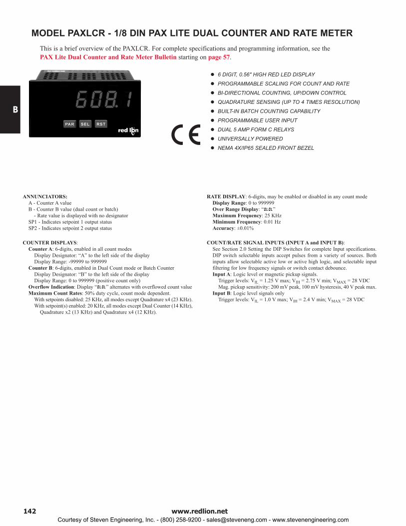
6 DIGIT, 0.56" HIGH RED LED DISPLAY
PROGRAMMABLE SCALING FOR COUNT AND RATE
BI-DIRECTIONAL COUNTING, UP/DOWN CONTROL
QUADRATURE SENSING (UP TO 4 TIMES RESOLUTION)
BUILT-IN BATCH COUNTING CAPABILITY
PROGRAMMABLE USER INPUT
DUAL 5 AMP FORM C RELAYS
UNIVERSALLY POWERED
NEMA 4X/IP65 SEALED FRONT BEZEL
MODEL PAXLCR - 1/8 DIN PAX LITE DUAL COUNTER AND RATE METERThis is a brief overview of the PAXLCR. For complete specifications and programming information, see the PAX Lite Dual Counter and Rate Meter Bulletin starting on page 57.
ANNUNCIATORS: A - Counter A valueB - Counter B value (dual count or batch) - Rate value is displayed with no designatorSP1 - Indicates setpoint 1 output statusSP2 - Indicates setpoint 2 output status
COUNTER DISPLAYS:Counter A: 6-digits, enabled in all count modes
Display Designator: “A” to the left side of the displayDisplay Range: -99999 to 999999
Counter B: 6-digits, enabled in Dual Count mode or Batch CounterDisplay Designator: “B” to the left side of the displayDisplay Range: 0 to 999999 (positive count only)
Overflow Indication: Display “” alternates with overflowed count valueMaximum Count Rates: 50% duty cycle, count mode dependent.
With setpoints disabled: 25 KHz, all modes except Quadrature x4 (23 KHz).With setpoint(s) enabled: 20 KHz, all modes except Dual Counter (14 KHz),
Quadrature x2 (13 KHz) and Quadrature x4 (12 KHz).
RATE DISPLAY: 6-digits, may be enabled or disabled in any count modeDisplay Range: 0 to 999999Over Range Display: “”Maximum Frequency: 25 KHzMinimum Frequency: 0.01 HzAccuracy: ±0.01%
COUNT/RATE SIGNAL INPUTS (INPUT A and INPUT B):See Section 2.0 Setting the DIP Switches for complete Input specifications. DIP switch selectable inputs accept pulses from a variety of sources. Both inputs allow selectable active low or active high logic, and selectable input filtering for low frequency signals or switch contact debounce.Input A: Logic level or magnetic pickup signals.
Trigger levels: VIL = 1.25 V max; VIH = 2.75 V min; VMAX = 28 VDCMag. pickup sensitivity: 200 mV peak, 100 mV hysteresis, 40 V peak max.
Input B: Logic level signals onlyTrigger levels: VIL = 1.0 V max; VIH = 2.4 V min; VMAX = 28 VDC
Courtesy of Steven Engineering, Inc. - (800) 258-9200 - [email protected] - www.stevenengineering.com

B
1431-717-767-6511
C US LISTEDULR
51EBIND. CONT. EQ.
ANNUNCIATORS: A - Counter AB - Counter BC - Counter C - Upper significant digit display of counterSP1 - setpoint 1 output stateSP2 - setpoint 2 output stateSP3 - setpoint 3 output stateSP4 - setpoint 4 output state
COUNTER DISPLAYS:Maximum display: 8 digits: ± 99999999 (greater than 6 digits display
Alternates between high order and low order.)INPUTS A and B:
DIP switch selectable to accept pulses from a variety of sources including switch contacts, TTL outputs, magnetic pickups and all standard RLC sensors.
LOGIC: Input trigger levels VIL = 1.5 V max.; VIH = 3.75 V min.Current sinking: Internal 7.8 KΩ pull-up to +12 VDC, IMAX = 1.9 mA.Current sourcing: Internal 3.9 KΩ pull-down, 7.3 mA max. @ 28 VDC,
VMAX = 30 VDC.Filter: Damping capacitor provided for switch contact bounce. Limits
input frequency to 50 Hz and input pulse widths to 10 msec. minimum.DUAL COUNT MODES:
When any dual count mode is used, then User Inputs 1 and/or 2 will accept the second signal of each signal pair. The user inputs do not have the Logic/Mag, HI/LO Freq, and Sink/Source input setup switches. The user inputs are inherently a logic input with no low frequency filtering. Any mechanical contacts used for these inputs in a dual count mode must be debounced externally. The user input may only be selected for sink/source by the User Jumper placement.
6-DIGIT 0.56" RED SUNLIGHT READABLE OR STANDARD GREEN DISPLAY (Alternating 8 digits for counting)
DUAL COUNT QUAD INPUTS UP TO 3 COUNT DISPLAYS FOUR SETPOINT ALARM OUTPUTS (W/Plug-in card)
PAXC SPECIFICATIONSMAXIMUM SIGNAL FREQUENCIES:
To determine the maximum frequency for the input(s), first answer the questions with a yes (Y) or no (N). Next determine the Count Mode to be used for the counter(s). If dual counters are used with different Count Modes, then the lowest frequency applies to both counters.
Notes:1. Counter Modes are explained in the Module 1 programming section.2. Listed values are with frequency DIP switch set on HI frequency.
FUNCTION QUESTIONS Dual: Counter A & BSingle: Counter A or BAre any setpoints used? N N Y Y N N Y YIs Counter C used? N Y N Y N Y N YCOUNT MODE (Values are in KHz) (Values are in KHz)Count x1 34 25 18 15 13 12 9 7.5Count x2 17 13 9 7 9 7 5 4Quadrature x1 22 19 12 10 7 6 4 3.5Quadrature x2 17 13 9 7 7 6 4 3.5Quadrature x4 8 6 4 3
MODEL PAXC - 1/8 DIN COUNTERThis is a brief overview of the PAXC. For complete specifications and programming information, see the PAX Digital Input Panel Meters Bulletin starting on page 68.
Courtesy of Steven Engineering, Inc. - (800) 258-9200 - [email protected] - www.stevenengineering.com

B
144 www.redlion.net
MODEL PAXI - 1/8 DIN DUAL COUNTER/RATE METER
ANNUNCIATORS: A - Counter AB - Counter BC - Counter C - Rate - Maximum (High) Rate - Minimum (Low) Rate - Upper significant digit display of counterSP1 - setpoint 1 output stateSP2 - setpoint 2 output stateSP3 - setpoint 3 output stateSP4 - setpoint 4 output state
RATE DISPLAY: Accuracy: ±0.01%Minimum Frequency: 0.01 HzMaximum Frequency: see Max Signal Frequencies Table.Maximum Display: 5 Digits: 99999Adjustable Display (low) Update: 0.1 to 99.9 secondsOver Range Display: “ ”
COUNTER DISPLAYS:Maximum display: 8 digits: ± 99999999 (greater than 6 digits displayAlternates between high order and low order.)
INPUTS A and B:DIP switch selectable to accept pulses from a variety of sources including switch contacts, TTL outputs, magnetic pickups and all standard RLC sensors.
LOGIC: Input trigger levels VIL = 1.5 V max.; VIH = 3.75 V min.Current sinking: Internal 7.8 KΩ pull-up to +12 VDC, IMAX = 1.9 mA.Current sourcing: Internal 3.9 KΩ pull-down, 7.3 mA max. @ 28 VDC,
VMAX = 30 VDC.Filter: Damping capacitor provided for switch contact bounce. Limits input
frequency to 50 Hz and input pulse widths to 10 msec. minimum.MAGNETIC PICKUP:
Sensitivity: 200 mV peakHysteresis: 100 mVInput impedance: 3.9 KΩ @ 60 HzMaximum input voltage: ±40 V peak, 30 Vrms
DUAL COUNT MODES:When any dual count mode is used, then User Inputs 1 and/or 2 will accept the second signal of each signal pair. The user inputs do not have the Logic/Mag, HI/LO Freq, and Sink/Source input setup switches. The user inputs are inherently a logic input with no low frequency filtering. Any mechanical contacts used for these inputs in a dual count mode must be debounced externally. The user input may only be selected for sink/source by the User Jumper placement.
PRESCALER OUTPUT:NPN Open Collector: ISNK = 100 mA max. @ VOL = 1 VDC max. VOH = 30
VDC max. With duty cycle of 25% min. and 50 % max.
PAXI SPECIFICATIONSMAXIMUM SIGNAL FREQUENCIES TABLE
To determine the maximum frequency for the input(s), first answer the questions with a yes (Y) or no (N). Next determine the Count Mode to be used for the counter(s). If dual counters are used with different Count Modes, then the lowest frequency applies to both counters.
COUNTER, DUAL COUNTER, RATE AND SLAVE DISPLAY 6-DIGIT 0.56" RED SUNLIGHT READABLE OR STANDARD
GREEN DISPLAY VARIABLE INTENSITY DISPLAY 10 POINT SCALING (FOR NON-LINEAR PROCESSES) FOUR SETPOINT ALARM OUTPUTS (W/OPTION CARD) RETRANSMITTED ANALOG OUTPUT (W/OPTION CARD) COMMUNICATION AND BUS CAPABILITIES (W/OPTION CARD) BUS CAPABILITIES; DEVICENET, MODBUS, AND PROFIBUS-DP CRIMSON PROGRAMMING SOFTWARE
This is a brief overview of the PAXI. For complete specifications and programming information, see thePAX Digital Input Panel Meters Bulletin starting on page 68.
C US LISTEDULR
51EBIND. CONT. EQ.
FUNCTION QUESTIONS Single: Counter A or B (with/without rate) or Rate only Dual: Counter A & B or Rate not assigned to active single counterAre any setpoints used? N N N N Y Y Y Y N N N N Y Y Y YIs Prescaler Output used? N N Y Y N N Y Y N N Y Y N N Y YIs Counter C used? N Y N Y N Y N Y N Y N Y N Y N YCOUNT MODE (Values are in KHz) (Values are in KHz) (Values are in KHz) (Values are in KHz)Count x1 34 25 21 17 18 15 13 11 13 12 13 11 9 7.5 9 7
Count x2 17 13 16 12 9 7 8 7 9 * 7 * 9 * 7 * 5 * 4 * 5 * 4 *
Quadrature x1 22 19 20 17 12 10 11 10 7 * 6 * 6 * 5 * 4 * 3.5 * 3.5 * 3 *
Quadrature x2 17 13 16 12 9 7 8 6 7 * 6 * 6 * 5 * 4 * 3.5 * 3.5 * 3 *
Quadrature x4 8 6 8 6 4 3 4 3
Rate Only 34 N/A 21 N/A 34 N/A 21 N/A
Courtesy of Steven Engineering, Inc. - (800) 258-9200 - [email protected] - www.stevenengineering.com

B
1451-717-767-6511
MODEL PAX2D - 1/8 DIN DIGITAL INPUT PANEL METER
COUNT, DUAL COUNTER WITH MATH FUNCTIONS RATE, DUAL RATE WITH MATH FUNCTIONS SLAVE DISPLAY UNIVERSAL AC/DC POWER SUPPLY 6 / 9 DIGIT DUAL LINE/TRI-COLOR DISPLAY WITH 0.71" & 0.35"
DIGITS 10 POINT RATE SCALING FOR NON-LINEAR PROCESSES PROGRAMMABLE UNITS DISPLAY BUS CAPABILITIES; DEVICENET, Modbus, AND PROFIBUS-DP BUILT-IN USB PROGRAMMING PORT ENABLING UNIT
CONFIGURATION WITH CRIMSON PROGRAMMING SOFTWARE NEMA 4X/IP65 SEALED FRONT BEZEL
This is a brief overview of the PAX2D. For complete specifications and programming information, see thePAX2D Digital Input Panel Meter Bulletin starting on page 98.
C US LISTEDULR
3RSDPROCESS CONTROL EQUIPMENT
SPECIFICATIONSPOWER:
AC Power: 40 to 250 VAC, 50/60 Hz, 20 VADC Power: 21.6 to 250 VDC, 8 WIsolation: 2300 Vrms for 1 min. to all inputs and outputs.
INPUTS A and B:DIP switch selectable to accept pulses from a variety of sources including switch contacts, TTL outputs, magnetic pickups and all standard RLC sensors.
LOGIC: Input trigger levels VIL = 1.5 V max.; VIH = 3.75 V min.Current sinking: Internal 7.8 KΩ pull-up to +5 VDC, IMAX = 0.7 mA.Current sourcing: Internal 3.9 KΩ pull-down, 7.3 mA max. @ 28 VDC,
VMAX = 30 VDC.Filter: Damping capacitor provided for switch contact bounce. Limits
input frequency to 50 Hz and input pulse widths to 10 msec. minimum.MAGNETIC PICKUP:
Sensitivity: 200 mV peakHysteresis: 100 mVInput impedance: 3.9 KΩ @ 60 Hz; Must also have SRC switch ON. (Not
recommended with counting applications.)Maximum input voltage: ±40 V peak, 28 Vrms
DUAL COUNT MODES:When any dual count mode is used, then User Inputs 1 and/or 2 will accept the second signal of each signal pair. The user inputs do not have the Logic/Mag, HI/LO Freq, and Sink/Source input setup switches. The user inputs are inherently a logic input with no low frequency filtering. Any mechanical contacts used for these inputs in a dual count mode must be debounced externally. The user input may only be selected for sink/source by the User Jumper placement.
SENSOR POWER: +18 VDC, ± 5% @ 60 mA max.; short circuit protected
USER INPUTS: Three programmable user inputsMax. Continuous Input: 30 VDCIsolation To Sensor Input Common: Not isolated.
PRESCALER OUTPUT:NPN Open Collector: ISNK = 100 mA max. @ VOL = 1 VDC max. VOH = 30
VDC max. Duty cycle 25% min. and 50 % max.ENVIRONMENTAL CONDITIONS:
Operating Temperature Range: 0 to 50 °CStorage Temperature Range: -40 to 60 °CVibration to IEC 68-2-6: Operational 5-150 Hz, 2 gShock to IEC 68-2-27: Operational 25 g (10 g relay)Operating and Storage Humidity: 0 to 85% max. RH non-condensingAltitude: Up to 2000 meters
CERTIFICATIONS AND COMPLIANCES:CE Approved
EN 61326-1 Immunity to Industrial LocationsEmission CISPR 11 Class AIEC/EN 61010-1RoHS Compliant
UL Listed: File #E179259Type 4X Indoor Enclosure rating (Face only)IP65 Enclosure rating (Face only)IP20 Enclosure rating (Rear of unit)
CONNECTIONS: High compression cage-clamp terminal blockWire Strip Length: 0.3" (7.5 mm)Wire Gauge Capacity: One 14 AWG (2.55 mm) solid,
two 18 AWG (1.02 mm) or four 20 AWG (0.61 mm)CONSTRUCTION: This unit is rated NEMA 4X/IP65 for indoor use only.
IP20 Touch safe. Installation Category II, Pollution Degree 2. One piece bezel/ case. Flame resistant. Synthetic rubber keypad. Panel gasket and mounting clip included.
WEIGHT: 8 oz. (226.8 g)
Courtesy of Steven Engineering, Inc. - (800) 258-9200 - [email protected] - www.stevenengineering.com

B
146 www.redlion.net
This page intentionally left blank.
Courtesy of Steven Engineering, Inc. - (800) 258-9200 - [email protected] - www.stevenengineering.com