Embed Size (px)
Citation preview

LANL Engineering Standards Manual STD-342-100 Chapter 17, Pressure Safety Attachment ADMIN-1-3 Rev. 0, 9/17/2014
Existing (including Legacy) System Documentation Requirements
Existing (including Legacy) System Documentation Requirements1
RECORD OF REVISIONS
Rev Date Description POC RM
0 9/17/2014 Initial issue. Modification of Table 16.1 of
Chapter 17, Section I, rev. 3.
Ari Ben Swartz,
ES-EPD
Larry Goen,
ES-DO
Contact the Standards POC for upkeep, interpretation, and variance issues.
Chapter 17 Pressure Safety POC and Committee
This document is online at http://engstandards.lanl.gov
Table ADMIN-1-3-1
Documentation Requirements for Existing (including Legacy) Systems
Documentation Package Item Required When Owner
Verification
PSO
Verification
1. Form 1, LANL Pressure System
Certification Status Form
Every Package
2. Form 3, Code Non-Compliance Log
(Form can be printed from Pressure
Safety Database by PSO)
If Applicable
1 The requirements for existing systems reflect the graded approach described in other sections of this Chapter, and take credit for successful operating history.

LANL Engineering Standards Manual STD-342-100 Chapter 17, Pressure Safety Attachment ADMIN-1-3 Rev. 0, 9/17/2014
Existing (including Legacy) System Documentation Requirements
Documentation Package Item Required When Owner
Verification
PSO
Verification
3. Form 4, Minor Non-Compliance Log
(Form can be printed from Pressure
Safety Database by PSO)
If Applicable
4. System schematics (If the owner does
not have a system schematic, utilize the
sketch prepared by the walkdown team
until such time as system schematic is
prepared)2
Every Package
5. Alternate Method/Variance or
clarification/interpretation (if
applicable).
If the system or any item of the system has an
applicable alternate method/variance or
clarification/interpretation to the requirements of
this document
6. Code Stamped Vessel Fabrication
Documentation
If the code data report is not available, a
manufacturer’s construction drawing may be
used to verify the item has not been modified.
If the manufacturer’s construction drawing is not
available, personal knowledge may be used to
establish the code stamped item has not been
modified. This requires a person or persons with
intimate and long term personal knowledge since
original receipt and installation of the item to
create a statement of compliance. This statement
of compliance will be used to document the
history of the item and be used as evidence the
code stamped item has not been modified. This
statement of compliance will be signed by the
persons of record.
7. Non-ASME code Fabricated Vessel
Information (code-equivalent
Documentation)
The pressure system contains Non-ASME-code
stamped boilers and pressure vessels (which
includes boilers, pressure vessels, heat
exchangers, and accumulators)
2 Information required on system schematics may be documented in alternative documents or captured in controlled databases, such as the Master Equipment List (MEL) or
Computerized Maintenance Management System (CMMS), but must be referenced and readily available for review. The evaluation shall be considered a record and must be
managed per LANL P1020, P1020-1, and P1020-2

LANL Engineering Standards Manual STD-342-100 Chapter 17, Pressure Safety Attachment ADMIN-1-3 Rev. 0, 9/17/2014
Existing (including Legacy) System Documentation Requirements
Documentation Package Item Required When Owner
Verification
PSO
Verification
a. ASME code equivalent
documentation for systems with
pressure vessels which includes
but is not limited to minimum
wall thickness determination,
corrosion allowance, weld
efficiency rating, support
structure loading, nozzle
calculations. Calculations will
use the material values specified
in the ASME code.
A non-code boiler, pressure vessel, heat
exchanger or accumulator is in the pressure
system package
b. Pressure Qualification Test
Procedures and data OR in-
service leak test for FS2 and FS3
as allowed in ESM Chapter 17.
Non-code boiler, pressure vessel, heat exchanger
or accumulator is in the pressure system package
c. Modification
procedures/instructions
Modifications were made to non-code boilers,
pressure vessels, heat exchangers or accumulators
is in the pressure system package
d. Non-Destructive Evaluation
(NDE) data reports
NDE was done to non-code boilers, pressure
vessels, heat exchangers or accumulators is in the
pressure system package
e. Weld examination forms as
described in ESM Chapter 13.
Welding was done to non-code boilers, pressure
vessels, heat exchangers or accumulators is in the
pressure system package
f. Special Calculations such as
welding
Special calculations are performed for non-code
boilers, pressure vessels, heat exchangers or
accumulators is in the pressure system package
g. Vendor Drawings Piece parts are used to fabricate non-code boilers,
pressure vessels, heat exchangers or accumulators
is in the pressure system package
h. Vessel modification reports Vessel is modified from the as purchased
condition.
8. Pressure Safety Devices The pressure system contains a pressure safety
device (which includes but is not limited to relief
valves and rupture discs)

LANL Engineering Standards Manual STD-342-100 Chapter 17, Pressure Safety Attachment ADMIN-1-3 Rev. 0, 9/17/2014
Existing (including Legacy) System Documentation Requirements
Documentation Package Item Required When Owner
Verification
PSO
Verification
a. Flow Test documentation as
described in this Chapter, if
required
Whenever a relief valve has been modified, or
when calculations cannot be generated.
b. Safety Relief Calculations for
relief valves and/or rupture discs,
in accordance with ASME
requirements
Every Package, unless calculations cannot be
generated, a flow test is required in place of
calculations.
c. Pressure Relief Calculations for
Rupture Disks in accordance with
ASME requirements
Rupture Disks are in the pressure system
d. Certified Test Data of relief
valves, e.g. steam Pressure safety
valves are certified by NBIC
coded shop
A PRD is modified or tested by an outside facility
e. Documentation of relief valve
modification, (for example valve
repair, orifice replacement,
gasket replacement,
If a relief valve has been modified
f. Identification as a liquid lock
PRD on PRV Recall Summary
Sheet and pressure system
Component List spread sheet; in
accordance with ASME B&PV
Code
PRDs are used as protection against liquid lock
overpressure. See ASME B&PVC UG-128.
9. Piping System Documentation:
a. Provide documentation required
under Section 10.0 requirements
for “Pressure System Deficiency
Disposition Requirements for
Existing Pressure Systems”
The system contains pipe, tube, or other
components not classed as boilers or vessels.

LANL Engineering Standards Manual STD-342-100 Chapter 17, Pressure Safety Attachment ADMIN-1-3 Rev. 0, 9/17/2014
Existing (including Legacy) System Documentation Requirements
Documentation Package Item Required When Owner
Verification
PSO
Verification
b. Code required calculations e.g.
flexibility analysis, pipe supports,
wind loading, and seismic
loading. See specific code for
additional detail. (e.g. B31.3
paragraph 319 and 321)
A pressure system package contains piping
system components
10. Flexible pressure element external
visual inspection records (Form 5)
The system contains flexible hoses
11. Pump or compressor discharge pressure
curves, calculation, or table (If
available)
The pressure system contains pumps or
compressors
12. Oxygen System Hazard Analysis (if
applicable)
Pressure system is an oxygen system
REDUCED REQUIREMENTS (LOW RISK) System documentation requirements of Table ADMIN-1-3-1 may be reduced for legacy systems meeting the following criteria:
1. The pressure system is not subject to low-cycle fatigue (where significant plastic straining occurs).
2. High-cycle fatigue (where stresses and strains are largely confined to the elastic region) is controlled to less than 100,000 cycles for the
life of the pressure system.
3. Corrosion is not a significant factor.
4. There are no stress intensification factors for examples cracks or acute angles of pressure boundaries.
5. The system components have exhibited extensive, successful service experience under comparable conditions with similarly proportioned
components of the same or like materials.
6. The pressure system is not high pressure as defined by ASME B31.3 2010 Chapter IX.
7. The pressure system is fluid is not Category M fluid as defined by ASME B31.3 2010.
8. The pressure system fluid is not steam.
9. The pressure system does not operate in the creep range.
10. The pressure system is not an ASME Section I, IV, VIII, or XII stamped item or an unstamped item performing the same task (e.g. a code
equivalent vessel).
11. ASME B31.9, B31.5, or B31.3 Fluid Category Normal or D.

LANL Engineering Standards Manual STD-342-100 Chapter 17, Pressure Safety Attachment ADMIN-1-3 Rev. 0, 9/17/2014
Existing (including Legacy) System Documentation Requirements
When the above criteria are met, the system must pass an initial service leak test at the normal system operational pressures. Then, Table
ADMIN-1-3-1 items 7.b-f, 9.a-b, and 10 are not required and Table ADMIN-1-3-1 becomes Table ADMIN-1-3-1ALT as follows:
Table ADMIN-1-3-1ALT
Alternative Documentation Requirements for Existing (including Legacy) Systems3
Documentation Package Item Required When Owner
Verification
PSO
Verification
1. Form 1, LANL Pressure System
Certification Status Form
Every Package
2. Form 3, Code Non-Compliance Log
(Form can be printed from Pressure
Safety Database by PSO), or reference
on Form 1 to closed PFITS issue
numbers.
If Applicable
3. Form 4, Minor Non-Compliance Log
(Form can be printed from Pressure
Safety Database by PSO), or reference
on Form 1 to closed PFITS issue
numbers
If applicable
11
Compressed Air
with Receiver FS2, FS3 11 M YES YES YES No No YES No
12
Compressed Inert
Gases – DOT
Cylinders FS2, FS3 14 N YES YES YES No No No No
13
Compressed Air
Without Receiver FS2, FS3 12 P YES YES No No No No No
3 The requirements for existing systems reflect the graded approach described in other sections of this Chapter, and take credit for successful operating history.
Deleted: <#> Page Break<#>System schematics (If the owner does not have a system
schematic, utilize the sketch prepared by the walkdown team until such time as system schematic is prepared)4
...
Deleted: YES
Deleted: YES

LANL Engineering Standards Manual STD-342-100 Chapter 17, Pressure Safety Attachment ADMIN-1-3 Rev. 0, 9/17/2014
Existing (including Legacy) System Documentation Requirements
14
Compressed Inert
Gases – Building
Systems FS3 13 R YES YES YES No No No No
15
High Pressure –Low
Liquid Volume FS1 15 S YES YES No No No No No
16 Hydronic piping FS2, FS3 16 T YES YES No No No No No
17 Water Systems FS2, FS3 17 U YES YES No No No No No
1 Corrosive Service – A fluid service in which the internal fluid, or external environment, is expected to produce a progressive deterioration in the
pressure boundary material.
2 Evaluate oxygen systems as required in ASTM G128 and other referenced ASTM standards to determine the likelihood of fire.
(*Note: New Table Numbers “ADMIN-1-3-I”, “ADMIN-1-3-L”, “ADMIN-1-3-O”, and “ADMIN-1-3-Q” were not used to eliminate confusion)
Deleted: YES
Deleted: YES
Deleted: YES
Deleted: YES

LANL Engineering Standards Manual STD-342-100 Chapter 17, Pressure Safety Attachment ADMIN-1-3 Rev. 0, 9/17/2014
Existing (including Legacy) System Documentation Requirements
Deleted: General Legacy Pressure System Description for High
Pressure – Inert Pneumatic
Evaluation Category 1¶¶
Assumptions:
Fluid Service¶The system fluid service is a FS1 as defined by ESM Chapter 17
The pressure system fluid service is high pressure as define by
ASME B31.3 2010 Chapter IX. ¶Corrosion is not a significant factor. 
Materials of construction are compatible with the system fluid
service.¶System Operation
The pressure system is not subject to low-cycle fatigue (where significant plastic straining occurs).
High-cycle fatigue (where stresses and strains are largely confined to
the elastic region) is controlled to less than 100,000 cycles for the life of the pressure system.
The pressure system does not operate in the creep range.
There are no stress intensification factors for example cracks or acute angles of pressure boundaries.
System Hardware
The system components have exhibited extensive, successful service experience under comparable conditions with similarly proportioned
components of the same or like material.
The system is equipped with a properly sized, set, and functional pressure relief device(s), if needed, to protect against single point
failures. Relief device exhaust locations are properly sized and
located to protect personnel.¶There are no locations in the system that requires relief protection
that may be isolated from relief protection. 
Flexible hoses over 12 inches in length and in service pressure greater than 150 psig are restrained in accordance with ESM Chapter
17.
In response to the PISA on LANL Welding Program (circa 2004) representative accessible welds were visually inspected and are free
from indications. Solder or braze joints are not allowed.
External appearance is free from corrosion or indication of leakage.¶Failure Mode
A ductile failure mode is assumed (not brittle fracture).
Consequence of Failure¶The result of the failure will not result in serious personnel injury.
Safety Class
Applicable to ML4 only.¶¶
Documentation Requirements¶ ...

LANL Engineering Standards Manual STD-342-100 Chapter 17, Pressure Safety Attachment ADMIN-1-3 Rev. 0, 9/17/2014
Existing (including Legacy) System Documentation Requirements
General Legacy Pressure System Description for Compressed Inert Gases – DOT Cylinders
Evaluation Category 12
Assumptions:
Fluid Service
1. The system fluid service is FS2 or FS3 as defined by ESM Chapter 17
1.1. The pressure system fluid service is Category D as define by ASME B31.3 2016.
1.2. The pressure system fluid service is Category Normal as define by ASME B31.3 2016.
1.3. The pressure systems are within the scope of ASME B31.9-2017
1.4. The pressure systems are within the scope of ASME B31.5-2016
2. Materials of construction are compatible with the system fluid service.
System Operation
1. There are no stress intensification factors for example cracks or acute angles of pressure boundaries.
System Hardware
1. The system components have exhibited extensive, good operating history under comparable conditions with
similarly proportioned components of the same or like material.
2. The system is equipped with a properly sized, set, and functional pressure relief device(s), if needed, to protect
against single point failures. Relief device exhaust locations are properly sized and located to protect personnel.
3. There are no locations in the system that requires relief protection that may be isolated from relief protection.
4. Flexible hoses over 12 inches in length and in service pressure greater than 150 psig are restrained in
accordance with ESM Chapter 17.
5. System is constructed of metallic components.
6. External appearance is free from corrosion or indication of leakage.
Failure Mode
1. A ductile failure mode is assumed (leak before burst).
Consequence of Failure
1. The result of the failure will not result in serious personnel injury. Safe-guarding will be applied if necessary.
Safety Class
1. Applicable to ML1 through
Documentation Requirements
1. These Compressed Inert Gases – DOT Cylinders pressure systems shall be exempt from the requirements of
having code leak test documentation.
Deleted: 0
Deleted: 0
Deleted: 1
Deleted: successful service experience
Deleted: <#>In response to the PISA on LANL Welding Program (circa 2004) representative accessible welds were visually
inspected and are free from indications. Solder or braze joints are
not allowed.
Deleted: 4
Deleted: only.

LANL Engineering Standards Manual STD-342-100 Chapter 17, Pressure Safety Attachment ADMIN-1-3 Rev. 0, 9/17/2014
Existing (including Legacy) System Documentation Requirements
2. These Compressed Inert Gases – DOT Cylinders pressure systems may continue to use unlisted components
provided they are used within the temperature and pressure ratings of the manufacturer’s.
3. This equipment will be considered grandfathered and will not be replaced with like items. System shall be
upgraded to ASME compliance as items age out of service by attrition.
4. LANL ESM Chapter 17 documentation as required by Table ADMIN-1-3-N include: certification status form
(FM01) and relief device (FM02).
5. Existing Compressed Inert Gases – DOT Cylinders pressure systems may continue to use non-ASME stamped
vessels provided calculations are performed to verify code-equivalent ratings.
6. When vessels are included as part of the Compressed Inert Gases – DOT Cylinders pressure system they must
be evaluated for current MAWP based on the most applicable code or standard.
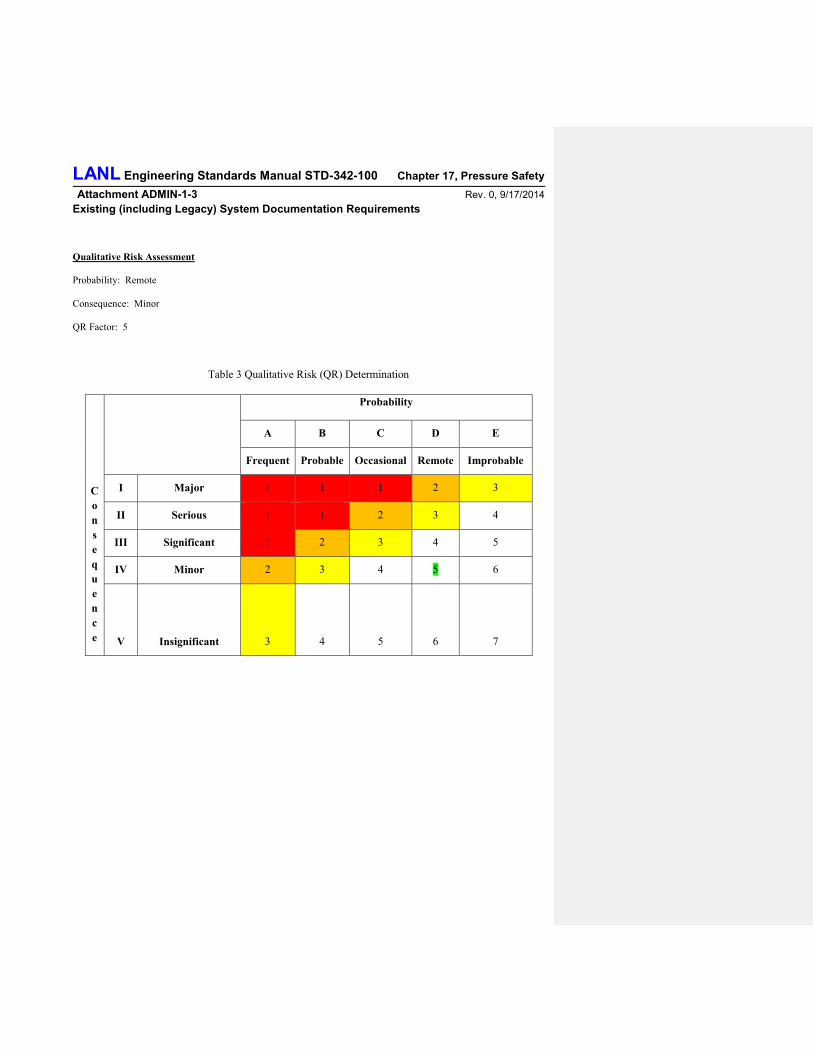
Qualitative Risk Assessment
Probability: Remote
Consequence: Significant
QR Factor: 5
Table 3 Qualitative Risk (QR) Determination
C
o
n
s
e
q
u
e
n
c
e
Probability
A B C D E
Frequent Probable Occasional Remote Improbable
I Major 1 1 1 2 3
II Serious 1 1 2 3 4
III Significant 1 2 3 4 5
IV Minor 2 3 4 5 6
V Insignificant 3 4 5 6 7
Deleted: ,
Deleted: , component list (FM07), and sketch (FM10).

LANL Engineering Standards Manual STD-342-100 Chapter 17, Pressure Safety Attachment ADMIN-1-3 Rev. 0, 9/17/2014
Existing (including Legacy) System Documentation Requirements
Table ADMIN-1-3-N
General Legacy Pressure System Documentation for Compressed Inert Gases – DOT Cylinders
Documentation Package Item Required When Owner
Verification
PSO
Verification
1. Form 1, LANL Pressure System Certification Status
Form
Every Package
2.
3. Alternate Method/Variance or
clarification/interpretation (if applicable).
If the system or any item of the system has an applicable alternate
method/variance or clarification/interpretation to the requirements of this
document
4. Code Stamped Vessel Fabrication Documentation If the code data report is not available, a manufacturer’s construction
drawing may be used to verify the item has not been modified.
If the manufacturer’s construction drawing is not available, personal
knowledge may be used to establish the code stamped item has not been
modified. This requires a person or persons with intimate and long term
personal knowledge since original receipt and installation of the item to
create a statement of compliance. This statement of compliance will be used
to document the history of the item and be used as evidence the code
stamped item has not been modified. This statement of compliance will be
signed by the persons of record.
a. Vessel thickness and remaining life estimate Every Package
5. Non-ASME code Fabricated Vessel Information
(code-equivalent Documentation)
The pressure system contains Non-ASME-code stamped boilers and pressure
vessels (which includes boilers, pressure vessels, heat exchangers, and
accumulators)
a. ASME code equivalent documentation for
systems with pressure vessels which includes but
is not limited to minimum wall thickness
determination, corrosion allowance, weld
efficiency rating, support structure loading,
nozzle calculations. Calculations will use the
material values specified in the ASME code.
A non-code boiler, pressure vessel, heat exchanger or accumulator is in the
pressure system package
Deleted: Page BreakForm 10, System schematics (If the owner does not have a system
schematic, utilize the sketch prepared by the walkdown team until
such time as system schematic is prepared)16
Deleted: Every Package

LANL Engineering Standards Manual STD-342-100 Chapter 17, Pressure Safety Attachment ADMIN-1-3 Rev. 0, 9/17/2014
Existing (including Legacy) System Documentation Requirements
Table ADMIN-1-3-N
General Legacy Pressure System Documentation for Compressed Inert Gases – DOT Cylinders
Documentation Package Item Required When Owner
Verification
PSO
Verification
b. Vessel thickness and remaining life estimate Every Package
6. Pressure Safety Devices The pressure system contains a pressure safety device (which includes but is
not limited to relief valves and rupture discs)
a. Safety Relief Calculations for relief valves, in
accordance with ASME requirements
Every Package, unless calculations cannot be generated, a flow test is
required in place of calculations.
b. Pressure Relief Calculations for Rupture Disks
in accordance with ASME requirements
Rupture Disks are in the pressure system
c. Certified Test Data of relief valves, e.g. steam
Pressure safety valves are certified by NBIC
coded shop
A PRD is modified or tested by an outside facility
7.
a.
8. Pump or compressor discharge pressure curves,
calculation, or table (If available)
The pressure system contains pumps or compressors
Deleted: Piping System Documentation:
Deleted: FM07; for available components
Deleted: Every Package

LANL Engineering Standards Manual STD-342-100 Chapter 17, Pressure Safety Attachment ADMIN-1-3 Rev. 0, 9/17/2014
Existing (including Legacy) System Documentation Requirements
General Legacy Pressure System Description for Compressed Air without Receiver
Evaluation Category 13
Assumptions:
Fluid Service
1. The system fluid service is FS2 or FS3 as defined by ESM Chapter 17
1.1. The pressure system fluid service is Category D as define by ASME B31.3 2016.
1.2. The pressure system fluid service is Category Normal as define by ASME B31.3 2016.
1.3. The pressure systems are within the scope of ASME B31.9-2017.
2. Materials of construction are compatible with the system fluid service.
System Operation
1. There are no stress intensification factors for example cracks or acute angles of pressure boundaries.
System Hardware
1. The system components have exhibited extensive, good operating history under comparable conditions with
similarly proportioned components of the same or like material.
2. The system is equipped with a properly sized, set, and functional pressure relief device(s), if needed, to protect
against single point failures. Relief device exhaust locations are properly sized and located to protect personnel.
3. There are no locations in the system that requires relief protection that may be isolated from relief protection.
4. Flexible hoses over 12 inches in length and in service pressure greater than 150 psig are restrained in
accordance with ESM Chapter 17.
5. System is constructed of metallic components.
6. External appearance is free from corrosion or indication of leakage.
Failure Mode
1. A ductile failure mode is assumed (leak before burst).
Consequence of Failure
1. The result of the failure will not result in serious personnel injury. Safe-guarding will be applied if necessary.
Safety Class
1. Applicable to ML1 thorugh only.
Documentation Requirements
1. These compressed air pressure systems shall be exempt from the requirements of having code leak test
documentation.
2. These compressed air pressure systems may continue to use unlisted components provided they are used within
the temperature and pressure ratings of the manufacturer’s.
Deleted: 0
Deleted: 0
Deleted: 1
Deleted: successful service experience
Deleted: <#>In response to the PISA on LANL Welding Program (circa 2004) representative accessible welds were visually
inspected and are free from indications. Solder or braze joints are not allowed.
Deleted: 4

LANL Engineering Standards Manual STD-342-100 Chapter 17, Pressure Safety Attachment ADMIN-1-3 Rev. 0, 9/17/2014
Existing (including Legacy) System Documentation Requirements
3. This equipment will be considered grandfathered and will not be replaced with like items. System shall be
upgraded to ASME compliance as items age out of service by attrition.
4. LANL ESM Chapter 17 documentation as required by Table ADMIN-1-3-P include: certification status form
(FM01), and relief device (FM02).
Qualitative Risk Assessment
Probability: Remote
Consequence: Minor
QR Factor: 4
Table 3 Qualitative Risk (QR) Determination
C
o
n
s
e
q
u
e
n
c
e
Probability
A B C D E
Frequent Probable Occasional Remote Improbable
I Major 1 1 1 2 3
II Serious 1 1 2 3 4
III Significant 1 2 3 4 5
IV Minor 2 3 4 5 6
V Insignificant 3 4 5 6 7
Deleted: , component list (FM07), and sketch (FM10).

LANL Engineering Standards Manual STD-342-100 Chapter 17, Pressure Safety Attachment ADMIN-1-3 Rev. 0, 9/17/2014
Existing (including Legacy) System Documentation Requirements
Table ADMIN-1-3-P
General Legacy Pressure System Description for Compressed Air without Receiver
Documentation Package Item Required When Owner
Verification
PSO
Verification
1. Form 1, LANL Pressure System Certification Status
Form
Every Package
2.
3. Alternate Method/Variance or
clarification/interpretation (if applicable).
If the system or any item of the system has an applicable alternate
method/variance or clarification/interpretation to the requirements of this
document
4. Pressure Safety Devices The pressure system contains a pressure safety device (which includes but is
not limited to relief valves and rupture discs)
a. Safety Relief Calculations for relief valves, in
accordance with ASME requirements
Every Package, unless calculations cannot be generated, a flow test is
required in place of calculations.
b. Pressure Relief Calculations for Rupture Disks
in accordance with ASME requirements
Rupture Disks are in the pressure system
c. Certified Test Data of relief valves, e.g. steam
Pressure safety valves are certified by NBIC
coded shop
A PRD is modified or tested by an outside facility
5.
a.
6. Pump or compressor discharge pressure curves,
calculation, or table (If available)
The pressure system contains pumps or compressors
Deleted: Page BreakForm 10, System schematics (If the owner does not have a system
schematic, utilize the sketch prepared by the walkdown team until
such time as system schematic is prepared)89
Deleted: Every Package
Deleted: Piping System Documentation:
Deleted: FM07; for available components
Deleted: Every Package

LANL Engineering Standards Manual STD-342-100 Chapter 17, Pressure Safety Attachment ADMIN-1-3 Rev. 0, 9/17/2014
Existing (including Legacy) System Documentation Requirements
General Legacy Pressure System Description for Compressed Inert Gases – Building Systems
Evaluation Category 14
Assumptions:
Fluid Service
1. The system fluid service is a FS3 as defined by ESM Chapter 17
1.1. The pressure system fluid service is Category D as define by ASME B31.3 2016.
1.2. The pressure system fluid service is Category Normal as define by ASME B31.3 2016. (liquids)
1.3. The pressure systems are within the scope of ASME B31.9-2017.
1.4. The pressure systems are within the scope of ASME B31.5-2016
2. Materials of construction are compatible with the system fluid service.
System Operation
1. There are no stress intensification factors for example cracks or acute angles of pressure boundaries.
System Hardware
1. The system components have exhibited extensive, good operating history under comparable conditions with
similarly proportioned components of the same or like material.
2. The system is equipped with a properly sized, set, and functional pressure relief device(s), if needed, to protect
against single point failures. Relief device exhaust locations are properly sized and located to protect personnel.
3. There are no locations in the system that requires relief protection that may be isolated from relief protection.
4. System is constructed of metallic components.
5. External appearance is free from corrosion or indication of leakage.
Failure Mode
1. A ductile failure mode is assumed (leak before burst).
Consequence of Failure
1. The result of the failure will not result in serious personnel injury. Safe-guarding will be applied if necessary.
Safety Class
1. Applicable to ML1 through 4.
Documentation Requirements
1. These Compressed Inert Gases – Building pressure systems shall be exempt from the requirements of having
code leak test documentation.
2. These Compressed Inert Gases – Building pressure systems may continue to use unlisted components provided
they are used within the temperature and pressure ratings of the manufacturer’s.
Deleted: 0
Deleted: 0
Deleted: 1
Formatted: Font: 10 pt
Deleted: successful service experience
Deleted: <#>In response to the PISA on LANL Welding Program (circa 2004) representative accessible welds were visually
inspected and are free from indications. Solder or braze joints are not allowed.
Deleted: only

LANL Engineering Standards Manual STD-342-100 Chapter 17, Pressure Safety Attachment ADMIN-1-3 Rev. 0, 9/17/2014
Existing (including Legacy) System Documentation Requirements
3. This equipment will be considered grandfathered and will not be replaced with like items. System shall be
upgraded to ASME compliance as items age out of service by attrition.
4. LANL ESM Chapter 17 documentation as required by Table ADMIN-1-3-R include: certification status form
(FM01) and relief device (FM02).
5. Existing Compressed Inert Gases – Building pressure systems may continue to use non-ASME stamped vessels
provided calculations are performed to verify code-equivalent ratings.
6. When vessels are included as part of the Compressed Inert Gases – Building pressure system they must be
evaluated for current MAWP based on the most applicable code or standard.
Qualitative Risk Assessment
Probability: Remote
Consequence: Minor
QR Factor: 5
Table 3 Qualitative Risk (QR) Determination
C
o
n
s
e
q
u
e
n
c
e
Probability
A B C D E
Frequent Probable Occasional Remote Improbable
I Major 1 1 1 2 3
II Serious 1 1 2 3 4
III Significant 1 2 3 4 5
IV Minor 2 3 4 5 6
V Insignificant 3 4 5 6 7
Deleted: ,
Deleted: , component list (FM07), and sketch (FM10).

LANL Engineering Standards Manual STD-342-100 Chapter 17, Pressure Safety Attachment ADMIN-1-3 Rev. 0, 9/17/2014
Existing (including Legacy) System Documentation Requirements
Table ADMIN-1-3-R
General Legacy Pressure System Documentation for Compressed Inert Gases - Buildings
Documentation Package Item Required When Owner
Verification
PSO
Verification
1. Form 1, LANL Pressure System Certification Status
Form
Every Package
2.
3. Alternate Method/Variance or
clarification/interpretation (if applicable).
If the system or any item of the system has an applicable alternate
method/variance or clarification/interpretation to the requirements of this
document
4. Code Stamped Vessel Fabrication Documentation If the code data report is not available, a manufacturer’s construction
drawing may be used to verify the item has not been modified.
If the manufacturer’s construction drawing is not available, personal
knowledge may be used to establish the code stamped item has not been
modified. This requires a person or persons with intimate and long term
personal knowledge since original receipt and installation of the item to
create a statement of compliance. This statement of compliance will be
used to document the history of the item and be used as evidence the code
stamped item has not been modified. This statement of compliance will be
signed by the persons of record.
a. Vessel thickness and remaining life estimate Every Package
5. Non-ASME code Fabricated Vessel Information
(code-equivalent Documentation)
The pressure system contains Non-ASME-code stamped boilers and
pressure vessels (which includes boilers, pressure vessels, heat exchangers,
and accumulators)
Deleted: Page BreakForm 10, System schematics (If the owner does not have a system
schematic, utilize the sketch prepared by the walkdown team until
such time as system schematic is prepared)18
Deleted: Every Package

LANL Engineering Standards Manual STD-342-100 Chapter 17, Pressure Safety Attachment ADMIN-1-3 Rev. 0, 9/17/2014
Existing (including Legacy) System Documentation Requirements
Table ADMIN-1-3-R
General Legacy Pressure System Documentation for Compressed Inert Gases - Buildings
Documentation Package Item Required When Owner
Verification
PSO
Verification
a. ASME code equivalent documentation for
systems with pressure vessels which includes
but is not limited to minimum wall thickness
determination, corrosion allowance, weld
efficiency rating, support structure loading,
nozzle calculations. Calculations will use the
material values specified in the ASME code.
A non-code boiler, pressure vessel, heat exchanger or accumulator is in the
pressure system package
b. Vessel thickness and remaining life estimate Every Package
6. Pressure Safety Devices The pressure system contains a pressure safety device (which includes but is
not limited to relief valves and rupture discs)
a. Safety Relief Calculations for relief valves, in
accordance with ASME requirements
Every Package, unless calculations cannot be generated, a flow test is
required in place of calculations.
b. Pressure Relief Calculations for Rupture Disks
in accordance with ASME requirements
Rupture Disks are in the pressure system
c. Certified Test Data of relief valves, e.g. steam
Pressure safety valves are certified by NBIC
coded shop
A PRD is modified or tested by an outside facility
7.
a.
8. Pump or compressor discharge pressure curves,
calculation, or table (If available)
The pressure system contains pumps or compressors
Deleted: Piping System Documentation:
Deleted: FM07; for available components
Deleted: Every Package

LANL Engineering Standards Manual STD-342-100 Chapter 17, Pressure Safety Attachment ADMIN-1-3 Rev. 0, 9/17/2014
Existing (including Legacy) System Documentation Requirements
General Legacy Pressure System Description for High Pressure – Low Liquid Volume
Evaluation Category 15
Assumptions:
Fluid Service
1. The system fluid service is a FS1 liquid with a low flow liquid rate such that whipping of flex lines is not an
issue.
1.1. The pressure system fluid service is High Pressure as define by ASME B31.3 2016.
1.2. The fluid used is not toxic, corrosive, or immediately dangerous to humans.
2. Materials of construction are compatible with the system fluid service.
System Operation
1. There are no stress intensification factors for example cracks or acute angles of pressure boundaries.
System Hardware
1. The system components have exhibited extensive, good operating history under comparable conditions with
similarly proportioned components of the same or like material.
2. The system is equipped with a properly sized, set, and functional pressure relief device(s), if needed, to protect
against single point failures. Relief device exhaust locations are properly sized and located to protect personnel.
3. There are no locations in the system that requires relief protection that may be isolated from relief protection.
4. Flexible hoses over 12 inches in length and in service pressure greater than 150 psig are restrained in
accordance with ESM Chapter 17 only in locations where adequate volume is present to present a whipping
problem.
5. Pumping rates are low enough to preclude hose whipping and fluid jetting from leaks.
6. System is constructed of metallic components.
7. External appearance is free from corrosion or indication of leakage.
Failure Mode
1. A ductile failure mode is assumed (leak before burst).
Consequence of Failure
1. The result of the failure will not result in serious personnel injury. Safe-guarding will be applied if necessary.
Safety Class
1. Applicable to ML1 through 4.
Documentation Requirements
Deleted: 0
Deleted: successful service experience
Deleted: <#>In response to the PISA on LANL Welding
Program (circa 2004) representative accessible welds were visually inspected and are free from indications. Solder or braze joints are
not allowed.
Deleted: ML4
Deleted: only

LANL Engineering Standards Manual STD-342-100 Chapter 17, Pressure Safety Attachment ADMIN-1-3 Rev. 0, 9/17/2014
Existing (including Legacy) System Documentation Requirements
1. These High Pressure – Low Liquid Volume pressure systems shall be exempt from the requirements of having
code leak test documentation.
2. These High Pressure – Low Liquid Volume pressure systems may continue to use unlisted components
provided they are used within the temperature and pressure ratings of the manufacturer’s.
3. This equipment will be considered grandfathered and will not be replaced with like items. System shall be
upgraded to ASME compliance as items age out of service by attrition.
4. LANL ESM Chapter 17 documentation as required by Table ADMIN-1-3-S include: certification status form
(FM01), relief device (FM02).
Qualitative Risk Assessment
Probability: Remote
Consequence: Significant
QR Factor: Insignificant
Table 3 Qualitative Risk (QR) Determination
C
o
n
s
e
q
u
e
n
c
e
Probability
A B C D E
Frequent Probable Occasional Remote Improbable
I Major 1 1 1 2 3
II Serious 1 1 2 3 4
III Significant 1 2 3 4 5
IV Minor 2 3 4 5 6
V Insignificant 3 4 5 6 7
Deleted: , component list (FM07), and sketch (FM10
Deleted: ).

LANL Engineering Standards Manual STD-342-100 Chapter 17, Pressure Safety Attachment ADMIN-1-3 Rev. 0, 9/17/2014
Existing (including Legacy) System Documentation Requirements
Table ADMIN-1-3-S
General Legacy Pressure System Documentation for High Pressure – Low Liquid Volume
Documentation Package Item Required When Owner
Verification
PSO
Verification
1. Form 1, LANL Pressure System Certification Status
Form
Every Package
2.
3. Alternate Method/Variance or
clarification/interpretation (if applicable).
If the system or any item of the system has an applicable alternate
method/variance or clarification/interpretation to the requirements of this
document
4. Pressure Safety Devices The pressure system contains a pressure safety device (which includes but is
not limited to relief valves and rupture discs)
a. Safety Relief Calculations for relief valves, in
accordance with ASME requirements
Every Package, unless calculations cannot be generated, a flow test is
required in place of calculations.
b. Pressure Relief Calculations for Rupture Disks
in accordance with ASME requirements
Rupture Disks are in the pressure system
c. Certified Test Data of relief valves, e.g. steam
Pressure safety valves are certified by NBIC
coded shop
A PRD is modified or tested by an outside facility
5.
a.
6. Pump or compressor discharge pressure curves,
calculation, or table (If available)
The pressure system contains pumps or compressors
Deleted: Page BreakForm 10, System schematics (If the owner does not have a system
schematic, utilize the sketch prepared by the walk down team until
such time as system schematic is prepared)19
Deleted: Every Package
Deleted: Piping System Documentation:
Deleted: FM07; for available components
Deleted: Every Package

LANL Engineering Standards Manual STD-342-100 Chapter 17, Pressure Safety Attachment ADMIN-1-3 Rev. 0, 9/17/2014
Existing (including Legacy) System Documentation Requirements
General Legacy Pressure System Description for Hydronic Piping
Evaluation Category 16
Assumptions:
Fluid Service
1. The system fluid service is FS3 as defined by ESM Chapter 17
1.1. The pressure system fluid service is Category D or Normal as defined by ASME B31.3 2016.
1.2. The pressure systems are within the scope of ASME B31.9-2017.
System Operation
1. There are no stress intensification factors for example cracks or acute angles of pressure boundaries.
System Hardware
1. The system components have exhibited extensive, good operating history under comparable conditions with
similarly proportioned components of the same or like material.
2. The system is equipped with a properly sized, set, and functional pressure relief device(s), if needed, to protect
against single point failures. Relief device exhaust locations are properly sized and located to protect personnel.
3. There are no locations in the system that requires relief protection that may be isolated from relief protection.
4. System is constructed of metallic components.
5. External appearance is free from corrosion or indication of leakage.
Failure Mode
1. A ductile failure mode is assumed (leak before burst).
Consequence of Failure
1. The result of the failure will not result in serious personnel injury. Safe-guarding will be applied if necessary.
Safety Class
1. Applicable to ML1 through 4.
Documentation Requirements
1. These hydronic pressure systems shall be exempt from the requirements of having code leak test
documentation.
2. These hydronic pressure systems may continue to use unlisted components provided they are used within the
temperature and pressure ratings of the manufacturer’s.
3. This equipment will be considered grandfathered and will not be replaced with like items. System shall be
upgraded to ASME compliance as items age out of service by attrition.
4. LANL ESM Chapter 17 documentation as required by Table ADMIN-1-3-T include: certification status form
(FM01), and relief device (FM02).
Deleted: 0
Deleted: 1
Deleted: successful service experience
Deleted: <#>In response to the PISA on LANL Welding Program (circa 2004) representative accessible welds were visually
inspected and are free from indications. Solder or braze joints are
not allowed.
Deleted: 4 only
Deleted: , component list (FM07), and sketch (FM10).
LANL Engineering Standards Manual STD-342-100 Chapter 17, Pressure Safety Attachment ADMIN-1-3 Rev. 0, 9/17/2014
Existing (including Legacy) System Documentation Requirements
Qualitative Risk Assessment
Probability: Remote
Consequence: Minor
QR Factor: 5
Table 3 Qualitative Risk (QR) Determination
C
o
n
s
e
q
u
e
n
c
e
Probability
A B C D E
Frequent Probable Occasional Remote Improbable
I Major 1 1 1 2 3
II Serious 1 1 2 3 4
III Significant 1 2 3 4 5
IV Minor 2 3 4 5 6
V Insignificant 3 4 5 6 7

LANL Engineering Standards Manual STD-342-100 Chapter 17, Pressure Safety Attachment ADMIN-1-3 Rev. 0, 9/17/2014
Existing (including Legacy) System Documentation Requirements
Table ADMIN-1-3-T
General Legacy Pressure System Documentation for Hydronic Piping
Documentation Package Item Required When Owner
Verification
PSO
Verification
1. Form 1, LANL Pressure System Certification Status Form Every Package
2.
3. Alternate Method/Variance or clarification/interpretation (if
applicable).
If the system or any item of the system has an applicable alternate
method/variance or clarification/interpretation to the requirements of this
document
4. Pressure Safety Devices The pressure system contains a pressure safety device (which includes but is
not limited to relief valves and rupture discs)
a. Safety Relief Calculations for relief valves, in accordance
with ASME requirements
Every Package, unless calculations cannot be generated, a flow test is
required in place of calculations.
b. Pressure Relief Calculations for Rupture Disks in
accordance with ASME requirements
Rupture Disks are in the pressure system
c. Certified Test Data of relief valves, e.g. steam Pressure
safety valves are certified by NBIC coded shop
A PRD is modified or tested by an outside facility
5.
a.
6. Pump or compressor discharge pressure curves, calculation, or
table (If available)
The pressure system contains pumps or compressors
Deleted: Page BreakForm 10, System schematics (If the owner does not have a system
schematic, utilize the sketch prepared by the walkdown team until such time as system schematic is prepared)20
Deleted: Every Package
Deleted: Piping System Documentation:
Deleted: FM07; for available components
Deleted: Every Package

LANL Engineering Standards Manual STD-342-100 Chapter 17, Pressure Safety Attachment ADMIN-1-3 Rev. 0, 9/17/2014
Existing (including Legacy) System Documentation Requirements
General Legacy Pressure System Description for Water Systems
Evaluation Category 17
Assumptions:
Fluid Service
1. The system fluid service is FS3 as defined by ESM Chapter 17
1.1. The pressure system fluid service is Category D or Normal as define by ASME B31.3 2016.
1.2. The pressure systems are within the scope of ASME B31.9-2017.
System Operation
1. There are no stress intensification factors for example cracks or acute angles of pressure boundaries.
System Hardware
1. The system components have exhibited extensive, good operating history under comparable conditions with
similarly proportioned components of the same or like material.
2. The system is equipped with a properly sized, set, and functional pressure relief device(s), if needed, to protect
against single point failures. Relief device exhaust locations are properly sized and located to protect personnel.
3. There are no locations in the system that requires relief protection that may be isolated from relief protection.
4. System is constructed of metallic components.
5. External appearance is free from corrosion or indication of leakage.
6. External appearance is free from corrosion or indication of leakage.
Failure Mode
1. A ductile failure mode is assumed (leak before burst).
Consequence of Failure
1. The result of the failure will not result in serious personnel injury. Safe-guarding will be applied if necessary.
Safety Class
1. Applicable to 1 through ML4.
Documentation Requirements
1. These water pressure systems shall be exempt from the requirements of having code leak test documentation.
2. These water pressure systems may continue to use unlisted components provided they are used within the
temperature and pressure ratings of the manufacturer’s.
3. This equipment will be considered grandfathered and will not be replaced with like items. System shall be
upgraded to ASME compliance as items age out of service by attrition.
Deleted: 0
Deleted: 1
Deleted: successful service experience
Deleted: <#>In response to the PISA on LANL Welding Program (circa 2004) representative accessible welds were visually
inspected and are free from indications. Solder or braze joints are
not allowed.
Deleted: 4 only

LANL Engineering Standards Manual STD-342-100 Chapter 17, Pressure Safety Attachment ADMIN-1-3 Rev. 0, 9/17/2014
Existing (including Legacy) System Documentation Requirements
4. LANL ESM Chapter 17 documentation as required by Table ADMIN-1-3-U include: certification status form
(FM01), and relief device (FM02).
Qualitative Risk Assessment
Probability: Remote
Consequence: Insignificant
QR Factor: 6
Table 3 Qualitative Risk (QR) Determination
C
o
n
s
e
q
u
e
n
c
e
Probability
A B C D E
Frequent Probable Occasional Remote Improbable
I Major 1 1 1 2 3
II Serious 1 1 2 3 4
III Significant 1 2 3 4 5
IV Minor 2 3 4 5 6
V Insignificant 3 4 5 6 7
Deleted: , component list (FM07), and sketch (FM10).

LANL Engineering Standards Manual STD-342-100 Chapter 17, Pressure Safety Attachment ADMIN-1-3 Rev. 0, 9/17/2014
Existing (including Legacy) System Documentation Requirements
Table ADMIN-1-3-U
General Legacy Pressure System Documentation for Water Systems
Documentation Package Item Comment Owner
Verification
PSO
Verification
1. Form 1, LANL Pressure System Certification Status Form Every Package
2.
3.
4. Alternate Method/Variance or clarification/interpretation (if
applicable).
If the system or any item of the system has an applicable alternate
method/variance or clarification/interpretation to the requirements of
this document
5. Pressure Safety Devices The pressure system contains a pressure safety device (which
includes but is not limited to relief valves and rupture discs)
a. Safety Relief Calculations for relief valves, in accordance
with ASME requirements
Every Package, unless calculations cannot be generated, a flow test is
required in place of calculations.
b. Pressure Relief Calculations for Rupture Disks in
accordance with ASME requirements
Rupture Disks are in the pressure system
c. Certified Test Data of relief valves, e.g. steam Pressure
safety valves are certified by NBIC coded shop
A PRD is modified or tested by an outside facility
6.
a.
7. Pump or compressor discharge pressure curves, calculation, or
table (If available)
The pressure system contains pumps or compressors
Deleted: Form 7, Component List
Deleted: Every Package
Deleted: Page BreakForm 10, System schematics (if the owner does not have a system
schematic, utilize the sketch prepared by the walkdown team until
such time as system schematic is prepared)21
Deleted: Every Package
Deleted: Piping System Documentation:
Deleted: FM07; for available components