Embed Size (px)
Citation preview
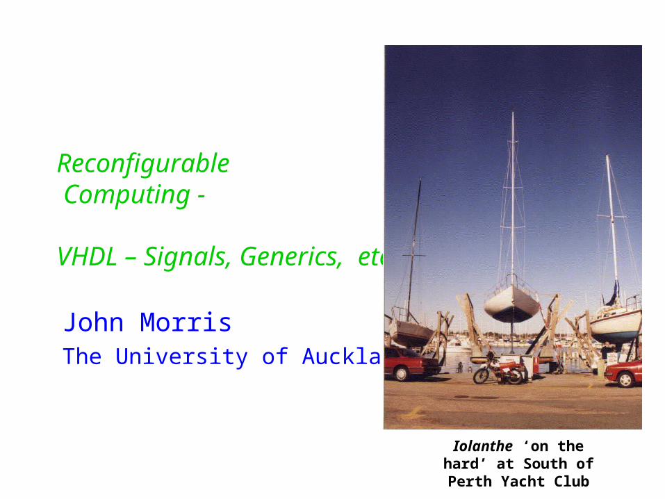
Reconfigurable Computing -
VHDL – Signals, Generics, etc
John MorrisThe University of Auckland
Iolanthe ‘on the hard’ at South of Perth Yacht Club

Shift Register
Remember Part outside the dashed yellow line is defined in the ENTITY It’s the interface with other circuit blocks
Inside the yellow line is defined in the ARCHITECTURE There may be several ways to achieve the same function!

Details of the PROCESSblock on the next slide
Example
Here’s the shift register in VHDL Entity first
Architecture
ENTITY shift_register IS PORT ( clk, reset, shift_in : IN std_logic; shift_out: OUT std_logic; q : OUT std_logic_vector );END shift_register;
ARCHITECTURE a OF shift_register IS SIGNAL q_int : std_logic_vector( q’RANGE ); BEGIN PROCESS( clk, reset ) ... END PROCESS; q <= q_int; shift_out <= q_int( q_int’HIGH );END a;

Aggregate initializer …full explanation later
Example
Here’s the shift register example again Process block
PROCESS( clk, reset ) BEGIN IF reset = ‘0’ THEN q_int <= ( OTHERS => ‘0’ ); ELSIF clk’EVENT AND clk = ‘1’ THEN q_int( q’LOW ) <= shift_in; FOR j IN q’LOW+1 TO q’HIGH LOOP q_int( j+1 ) <= q_int( j ); END LOOP; END IF; END PROCESS; q <= q_int; shift_out <= q_int( q_int’HIGH );END a;
Does this actually work?

???If these were assignments in a normal programming language, shift_in would be copied to each storage element in the register!
Shift Register Example
What happens if we write out the assignments, one by one? Look at the ‘q_int’ assignments only Use some real values for the indices
q_int( q’LOW ) <= shift_in;FOR j IN q’LOW+1 TO q’HIGH LOOP q_int( j ) <= q_int( j-1 ); END LOOP;
q_int(0) <= shift_in;q_int(1) <= q_int(0);q_int(2) <= q_int(1);…q_int(31) <= q_int(30);
However, this code is actually correct …and produces the desired behaviour of a shift register.
Why?

In this case, shift_in IS copied to each storage element in the register!
Shift Register Example
If we had used the standard assignment - := Then the statements would have been executed sequentially -
as in a normal programming language!
q_int( q’LOW ) := shift_in;FOR j IN q’LOW+1 TO q’HIGH LOOP q_int( j ) := q_int( j-1 ); END LOOP;
q_int(0) := shift_in;q_int(1) := q_int(0);q_int(2) := q_int(1);…q_int(31) := q_int(30);
However, with signal assignment ( <= ),
the story is different …

Shift Register Example
With signal assignment, all the assignments take place at the same time (in parallel) Each signal acquires its new value in the next simulation interval
q_int( q’LOW ) <= shift_in;FOR j IN q’LOW+1 TO q’HIGH LOOP q_int( j ) <= q_int( j-1 ); END LOOP;
q_int(0) <= shift_in;q_int(1) <= q_int(0);q_int(2) <= q_int(1);…q_int(31) <= q_int(30);
So in this set of statements, - all assignments take place at the same time and- all use the current values stored in q_intThe new values appear in q_int in the next simulation interval.

Signal assignment
Effectively, we are allowing for an infinitessimally small, but finite, propagation delay to drive a signal to its new value
Thus, even though a signal may be driven with a new value in a PROCESS block†, if it appears on the right in any assignment,its current value will be used.
This phenomenon is sometimes described in terms of the simulation delta - the smallest interval that a discrete event simulator will consider the infinitessimally small propagation delay
In contrast, ordinary assignments ( := ) are considered to take effect immediately, so the order in which a sequence of := operators appear may be significant!
† Note that the delayed assignment of new values applies to all signals – whether they’re in PROCESS blocks or data flow statements within an ARCHITECTURE

Signal assignment Another way of looking at signal assignment is to examine the
waveforms A shift register circuit looks something like this:
On clock edges, qk is transferred - after a delay - to qk+1
The waveforms look like this (with some arbitrary values given to the q’s):
D Q D Q D Q D Qq0 q1 q2 qn-1
q0
q1
q2
clk
These are the propagation
delays in a real circuit-
or
the deltas - intervals between
evaluations by the simulator

Declaring signals and variables
Signals are declared in the body of an architecture
Variables are declared in the body of a PROCESS block
ARCHITECTURE a OF entity_x IS SIGNAL a, b, c: std_logic := ‘0’; SIGNAL x, y: std_logic_vector( wordsize ); BEGIN ...END a;
PROCESS( clk, reset ) VARIABLE a, b, c: std_logic := ‘0’; VARIABLE x, y: std_logic_vector( wordsize ); BEGIN ...END PROCESS;

Signals and waveforms
You can specify precisely the delay for signal assignment
Synthesizers will generally ignore the “AFTER time” part,but you can use this capability to check for race conditions, etc, in the simulator by adding realistic delays to critical elements
A signal assignment may also be a waveform A sequence of values to be applied in turn to the target
This capability is very useful when setting up test benches You can generate test waveforms relatively painlessly!
x <= ‘0’ AFTER 5 ns;
x <= ‘0’ AFTER 5 ns, ‘1’ AFTER 7ns, ‘Z’ AFTER 2ns;

Conditional signal assignment
Creating a process block just so that you can write an IF … clause is somewhat painful ……
Conditional waveform elements alleviate the pain
This enables you to write dataflow models with simple choices in them - without needing to include the complex syntax of a PROCESS block!
A complex signal assignment can include a delay, a condition and a list of these ...
x <= ‘0’ WHEN enable = ‘0’ ELSE ‘Z’;
x <= ‘0’ AFTER 5 ns WHEN en = ‘0’ ELSE ‘Z’ AFTER 4 ns, ‘1’ AFTER 7ns WHEN grant = ‘1’ ELSE ‘Z’ AFTER 4 ns, … -- and several more if you need!

Example
Simple state machine to recognize “111” on wand output ‘1’ on z on success
ARCHITECTURE behavioural OF simple ISTYPE STATE_TYPE IS (A, B, C) ;SIGNAL y : STATE_TYPE ;
BEGINPROCESS ( reset, clk )BEGIN
IF reset = '0' THENy <= A ;
ELSIF (clk'EVENT AND clk = '1') THENCASE y IS
WHEN A =>IF w = '0' THEN y <= A ;ELSE y <= B ;END IF ;
WHEN B =>IF w = '0' THEN y <= A ;ELSE y <= C ;END IF ;
WHEN C =>IF w = '0' THEN y <= A ;ELSE y <= C ;END IF ;
END CASE ;END IF ;
END PROCESS ;z <= '1' WHEN y = C ELSE '0' ;
END behavioural;
One way to set state machine
outputs!

Initializing arrays
As we’ve already seen, it’s useful to be able to initialize arrays Arrays are aggregates (in the formal description of VHDL)
Use an aggregate initializer
The initializer is a list of the elements - separated by commas and enclosed in parentheses ( ..., …, …, … )
An initializer must include every element of an array, but There is a very convenient convention, which allows an array to be
‘finished off’ with OTHERS => value.
In fact, you can use OTHERS to set the whole array
This form has a significant advantage: it doesn’t need to be changed if the
length of the array is changed
SIGNAL x : std_logic_vector( 0 TO 15 );x <= ( ‘0’, ‘0’, ‘1’, OTHERS => ‘Z’ );
x <= ( OTHERS => ‘Z’ );

‘Slice’ Assignment
Often you need to assign part of a datapath to another signal or direct it to a component For example, in a CPU, you might want to ‘steer’ the op code
portion of an instruction to an instruction decoder
The instruction decoder is modeled with this entity
ENTITY inst_decoder IS PORT( opcode : IN std_logic_vector( 0 TO 7 ); inst_type : OUT std_logic_vector( 0 TO 36 ); );END inst_decoder;
Instruction decoder
Remainder of datapath
8
24
32
Instructionword

‘Slice’ Assignment
Often you need to assign part of a datapath to another signal or direct it to a component A slice assignment allows you to steer or select part of the vector
to another signal
or directly to an instantiated component:
id: inst_decoder( opcode => inst_word(0 TO 7), inst_type => … );
SIGNAL inst_word: std_logic_vector( 0 TO 31 );...opcode <= inst_word( 0 TO 7 );
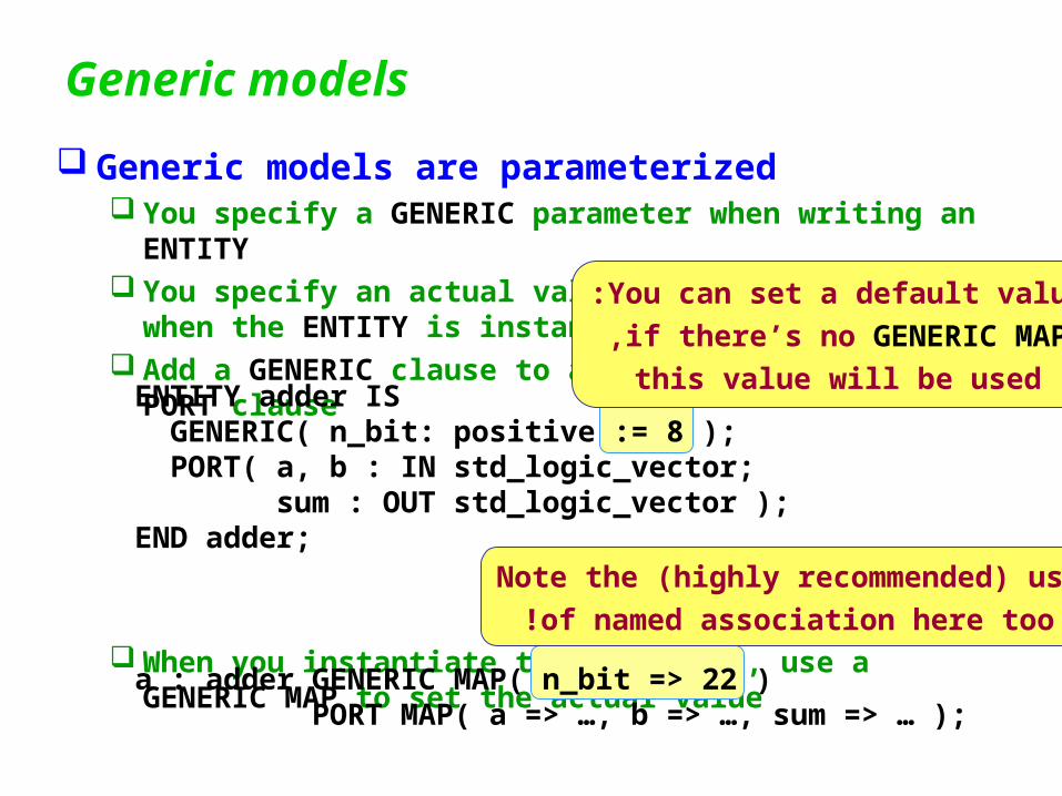
Generic models
Generic models are parameterized You specify a GENERIC parameter when writing an ENTITY You specify an actual values for this parameter when the ENTITY is instantiated
Add a GENERIC clause to an ENTITY before the PORT clause
When you instantiate the component, use a GENERIC MAP to set the actual value
You can set a default value:
if there’s no GENERIC MAP,
this value will be usedENTITY adder IS GENERIC( n_bit: positive := 8 ); PORT( a, b : IN std_logic_vector; sum : OUT std_logic_vector );END adder;
Note the (highly recommended) use
of named association here too!
a : adder GENERIC MAP( n_bit => 22 ) PORT MAP( a => …, b => …, sum => … );

Generic models
Generic models are flexible Almost anything can be a generic parameter! Another example
can be used for checking for race conditions The architecture is
ENTITY or2 IS GENERIC( td: time := 1 ns ); PORT( a, b : IN std_logic; c : OUT std_logic );END or2;
Remember that a synthesizer
will generally just ignore the
AFTER time phrase
ARCHITECTURE timed OF or2 IS BEGIN c <= a OR b AFTER td; END timed;
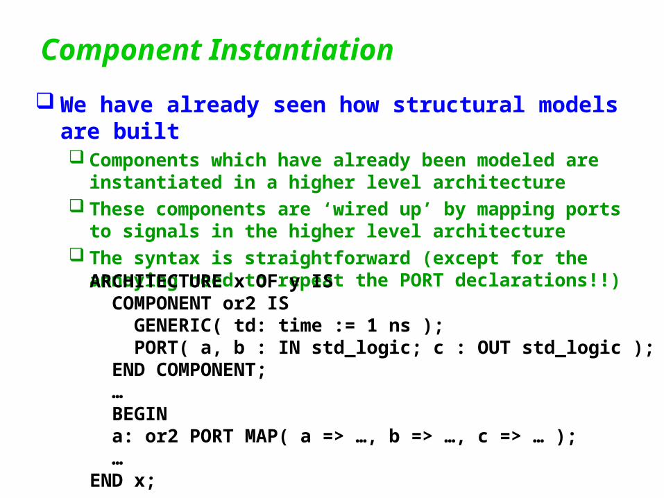
Component Instantiation
We have already seen how structural models are built Components which have already been modeled are
instantiated in a higher level architecture These components are ‘wired up’ by mapping ports to signals
in the higher level architecture The syntax is straightforward (except for the annoying need to
repeat the PORT declarations!!)
ARCHITECTURE x OF y IS COMPONENT or2 IS GENERIC( td: time := 1 ns ); PORT( a, b : IN std_logic; c : OUT std_logic ); END COMPONENT; … BEGIN a: or2 PORT MAP( a => …, b => …, c => … ); …END x;

Component Instantiation - Generate When multiple elements of a simple component are
needed, use GENERATE Permits rapid build-up of complex models The classic example is a ripple carry adder
ARCHITECTURE structural OF adder IS COMPONENT full_adder IS PORT( a, b, c : IN std_logic; s, c_out : OUT std_logic ); END COMPONENT; SIGNAL c_int : std_logic_vector( 0 TO n-1 ); BEGIN fa0: full_adder( a=>a(0), b=>b(0), c=>c_in, s=>sum(0), c_out => c_int(0); fa_blk: FOR j IN 1 TO n-1 GENERATE fa_j: full_adder(a(j),b(j),c_int(j-1), sum(j), c_int(j)); END GENERATE; c_out <= c_int( n-1 ); END structural;

Making sure your design is correct - ASSERT At many points in a design, it is possible to make assertions
about the state of signals and variables For example, in counting bits, you might know that there should
always be at least one bit set (because there is some statement in the problem specification that tells you this)
ARCHITECTURE a OF bitcounter IS BEGIN PROCESS VARIABLE count : natural := 0; BEGIN FOR j IN x’RANGE LOOP IF x(j) = ‘1’ THEN count := count + 1; END LOOP; cnt <= count; ASSERT count > 0 REPORT “bitcounter: zero count” SEVERITY warning; END PROCESS;END a;
Boolean expression which
should produce a TRUE
Message string-
Make it as useful as possible!
Cryptic error messages are sometimesas bad as no messages at all!
Can be warning | report | …Check your simulator for behaviour!

Making sure your design is correct - ASSERT ASSERT may not be supported by Altera’s MAX+ VHDL
(although their own AHDL supports it!) If so, this is a definite weakness in Altera’s VHDL!
ASSERT can save much time when debugging complex models!

Making your own library
For large system designs, you might want to make your own library
Simply create a PACKAGE (with all the declarations) and a PACKAGE BODY (with all the bodies or architectures)
A package declaration looks like this
Packages can contain types, subtypes, constants, procedures, functions, signals, files, components and several other less useful things
PACKAGE image_proc IS TYPE pixel IS std_logic_vector(0 TO 7); CONSTANT line_length : positive := 256; COMPONENT adder IS GENERIC( n_bit : positive := 8 ) PORT( a, b: std_logic_vector; … ); END COMPONENT;END PACKAGE;

Making your own library
The PACKAGE BODY contains procedure and function bodies Architectures are placed in secondary units
If you compile package bodies in the usual way, they will usually be placed in a library called work.
The work library is generally always accessible so the
clause may be omitted, but you will need to include
Check your simulator / synthesizer documentation for the exact story - this convention may not be universally followed!
PACKAGE BODY image_proc IS PROCEDURE BODY sobel IS ... END sobel;END PACKAGE;
LIBRARY work;
use work.image_proc.ALL;

Disclaimer*
This section of the course has covered only the most important features of VHDL There are many more! The Ada standard requires 400+ pages and VHDL has many
additional features! The features described to this point are sufficient for you to
write a wide variety of quite complex models However, if you undertake a serious modeling project in
VHDL, you should arm yourself with one of the texts and study the features passed over here!
*This disclaimer is brought to you by the American legal system - which makes them essential nowadays.
American lawyers don’t seem to have noticed that these disclaimers are becoming ridiculous - like those on software that typically say:
“You can expect this software to have bugs”
“We do not guarantee this software to do anything correctly”.
...

Other things Select? Packages? Arithmetic
+, - Multipliers Dividers Floating point

Example - GenerateENTITY adder IS
GENERIC ( n : INTEGER := 16 ) ;PORT ( c_in : IN std_ulogic ;
a, b : IN std_ulogic_vector(n-1 DOWNTO 0) ;sum : OUT std_ulogic_vector(n-1 DOWNTO 0) ;c_out : OUT std_ulogic ) ;
END adder;
ARCHITECTURE rc_structure OF adder ISSIGNAL c : STD_LOGIC_VECTOR(1 TO n-1) ;COMPONENT fulladd
PORT ( c_in, x, y : IN std_ulogic ;s, c_out : OUT std_ulogic ) ;
END COMPONENT ;BEGIN
FA_0: fulladd PORT MAP ( c_in=>c_in, x=>a(0), y=>b(0), s=>sum(0), c_out=>c(1) ) ;
G_1: FOR i IN 1 TO n-2 GENERATEFA_i: fulladd PORT MAP ( c(i), a(i), b(i), sum(i), c(i+1) ) ;
END GENERATE ;FA_n: fulladd PORT MAP (C(n-1),A(n-1),B(n-1),Sum(n-1),Cout) ;
END rc_structure ;

Exploiting a manufacturer’s fast carry logic To use the Altera fast carry logic, you need to write your adder
like this:LIBRARY ieee;USE ieee.std_logic_1164.all;LIBRARY lpm ;USE lpm.lpm_components.all ;
ENTITY adder ISPORT ( c_in : IN STD_LOGIC ;
a, b : IN STD_LOGIC_VECTOR(15 DOWNTO 0) ;sum : OUT STD_LOGIC_VECTOR(15 DOWNTO 0) ;c_out : OUT STD_LOGIC ) ;
END adderlpm ;
ARCHITECTURE lpm_structure OF adder ISBEGIN
instance: lpm_add_subGENERIC MAP (LPM_WIDTH => 16)PORT MAP ( cin => Cin, dataa => A, datab => B,
result => Sum, cout => Cout ) ;END lpm_structure ;

IEEE 1164 standard logic package Bus pull-up and pull-down resistors can be ‘inserted’
Initialise a bus signal to ‘H’ or ‘L’:
‘0’ or ‘1’ from any driver will override the weak ‘H’ or ‘L’:
SIGNAL not_ready : std_logic := ‘H’;
IF seek_finished = ‘1’ THEN not_ready <= ‘0’;END IF;
/ready
10k
VDD
DeviceA DeviceB DeviceC