Embed Size (px)
Citation preview

Reconfigurable Computing -Designing and Testing
John MorrisChung-Ang University
The University of Auckland
‘Iolanthe’ at 13 knots on Cockburn Sound, Western Australia

FPGA Architectures Design Flow
Good engineering practice requires that design exercises should follow a defined procedure
User’s specification This is your starting point It may take several forms
1. Informal requirements given to you by your user / client / …
2. Formal written requirements• All functional and non-functional requirements are precisely stated
• Sometimes resulting in a very large (and dull) document!
3. Something in between• Your tutorial assignment was in this category
• Mostly formal, but with some gaps you would need to fill in
• Using research / further discussion with client / … etc

Step 1 - Analysis
Design Step 1 – Analyze specification Identify suitable circuit modules by carefully reading
specification Start at top level – identify major components first
In particular, identify interfaces between environment and device that you’re designing
• Washing machine example:• Inputs - User buttons, dials, sensors, …• Outputs – Motors, indicator lights, audio, …
From these, specify the top-level entity
ENTITY wm IS
start, lid, stop : IN std_logic_vector;
audio : OUT audio_sample;…
END ENTITY wm;

Step 1 - Analysis
Design Step 1 – Analyze specification
Note that you may defer implementation details! In this case, you don’t want to bother with the details of the
audio output stream yet, so just specify a type audio_sample without filling in details for it yet.
Checking your design A VHDL compiler (usually the simulator’s compiler) should be
used to check completeness and consistency of a design from the early stages!
ENTITY wm IS
start, lid, stop : IN std_logic_vector;
audio : OUT audio_sample;…
END ENTITY wm;

Step 1a – Analysis : Checking the Design Design Step 1 – Analyze specification
Checking your design A VHDL compiler (usually the simulator’s compiler) should be
used to check completeness and consistency of a design from the early stages!
Even though many details are missing• Initially you may have no architecture blocks at all!
A compiler will warn you of missing, incomplete or inconsistent specifications
Thus although diagrams (and other informal modeling tools – like pencil and eraser!) are very useful,you should be generating formal (checkable) design specifications at a very early stage.
• These may be abstract• High level• Missing implementation details
but they are vital for detecting design errors!

Step 1a – Analysis : Checking the Design Design Step 1 – Analyze specification
Checking your design
In this example, you have deliberately deferred a decision about the exact form of audio_sample.
You will need to provide a definition of it for the compiler, but you can substitute anything that the compiler will accept at this stage!
Make a package
ENTITY wm IS
start, lid, stop : IN std_logic_vector;
audio : OUT audio_sample;…
END ENTITY wm;
PACKAGE audio IS
TYPE audio_sample IS integer RANGE 0 TO 255;
END PACKAGE audio;

Step 1a – Analysis : Checking the Design Design Step 1 – Analyze specification
Deferred detail ... Many possibilities exist for the deferred detail …
or
or
PACKAGE audio IS
TYPE audio_sample IS std_logic_vector(0 TO 7);
END PACKAGE audio;
PACKAGE audio IS
TYPE audio_sample IS std_logic_vector(sample_size);
END PACKAGE audio;
PACKAGE audio IS
TYPE audio_sample IS …; -- Your own idea!
END PACKAGE audio;
Key idea:
Use the compiler to check your design as much as possible!These deferred definitions are necessary to avoid messages like ‘xxx is undefined’which prevent the compiler from checking the rest of the design!

Step 2 - Refining the design
Once you have a formal VHDL specification for the high level entity for your design
Step 2 is to refine the design
wm (washing controller)
startlid
motor
stopvalves
audio

Step 2 - Refining the design
Step 2 is to refine the design Determine the internal structure of your component
What entities do we need to implement the requirements?
• Counters, timers, …
• State machines, … (overall control)
• Device controllers eg PWM for motors, display controllers, …
Write formal models (VHDL entities) for each internal componentENTITY count_down_timer IS
PORT( clk, reset : IN std_logic;
cycles : IN std_logic_vector; complete : OUT std_logic;(
END ENTITY count_down_timer;
ENTITY speech_synth IS
PORT;( … )
END ENTITY speech_synth;
ENTITY motor_control IS
PORT;( … )
END ENTITY motor_control;

Step 2 - Refining the design
Step 2 is to refine the design Determine the internal structure of your component Write formal models (VHDL entities) for each internal
component Determine how these models are connected
wm (washing controller)
startlid
motorstopvalves
audio
main_fsm
speech_synth
c_d_timer

Step 3 – Assemble the system
Step 3 – Build a model which includes all the componentsof the system you are building
ie write the ARCHITECTURE block Generally this will be a structural VHDL model VHDL models may be mixed, so this is not a hard rule!
startlid motor
stop valves
wm (washing controller)
audio
main_fsm
speech_synth
c_d_timer
ARCHITECTURE a OF wm IS
COMPONENT main_fsm PORT;( … )
COMPONENT speech_synth PORT;( … )
COMPONENT c_d_timer PORT;( … )
SIGNAL … BEGIN
fsm: main_fsm PORT MAP;( … )
t1: c_d_timer PORT MAP;( … )
END ARCHITECTURE a;
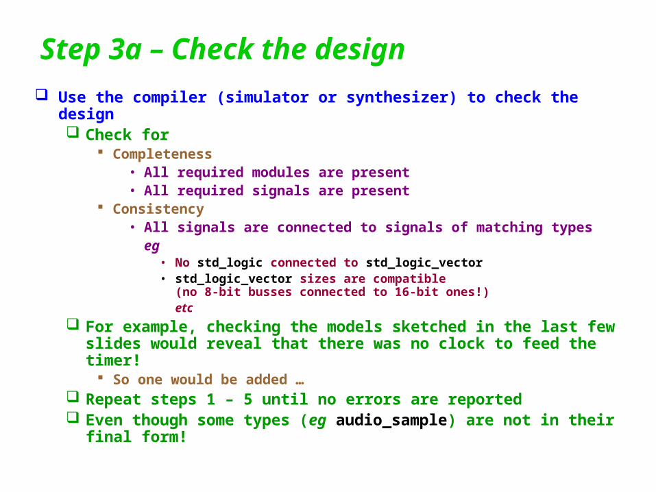
Step 3a – Check the design Use the compiler (simulator or synthesizer) to check the design
Check for Completeness
• All required modules are present• All required signals are present
Consistency• All signals are connected to signals of matching types
eg• No std_logic connected to std_logic_vector• std_logic_vector sizes are compatible
(no 8-bit busses connected to 16-bit ones!)etc
For example, checking the models sketched in the last few slides would reveal that there was no clock to feed the timer!
So one would be added … Repeat steps 1 – 5 until no errors are reported Even though some types (eg audio_sample) are not in their final
form!

Step 4 – Complete the details
Fill in all architectures You only need top-level structural architectures to check the
design! Now you need to complete them all!
Decide on all deferred types Any design decision that you deferred …
Add assertions! Don’t forget to try to make your design check itself
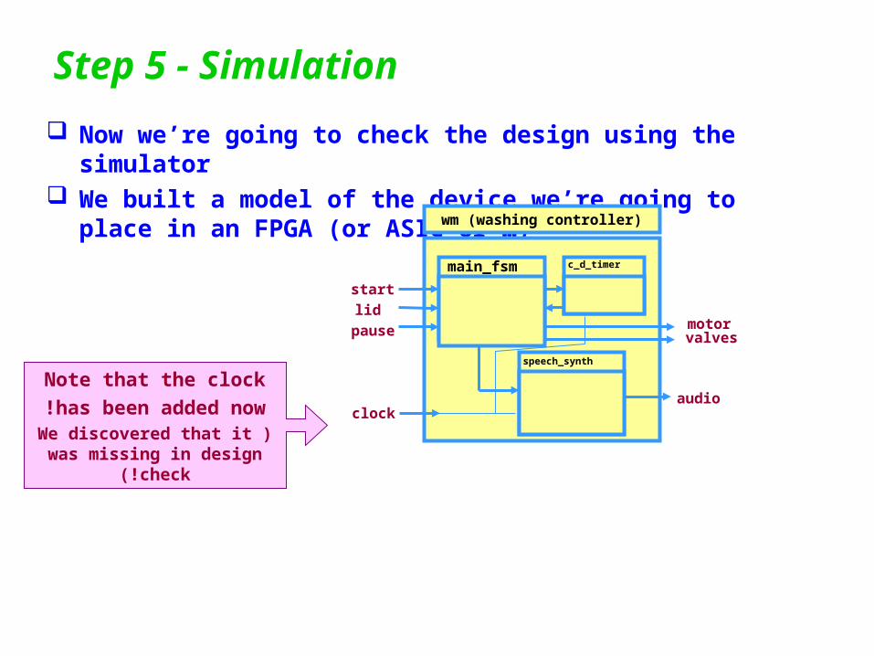
Step 5 - Simulation
Now we’re going to check the design using the simulator We built a model of the device we’re going to place in an FPGA
(or ASIC or …)wm (washing controller)
audio
main_fsm
speech_synth
c_d_timer
motor valves
start
lid
pause
clock
Note that the clock
has been added now!)We discovered that it
was missing in design check(!

Step 5 - Simulation
Build any additional models needed Clock model Models to simulate external devices
eg camera, printer, keyboard, …
Special models for generatingtest data
eg random data generators
wm (washing controller)
audio
main_fsm
speech_synth
c_d_timer
motor valves
start
lid
pause
clock
clock
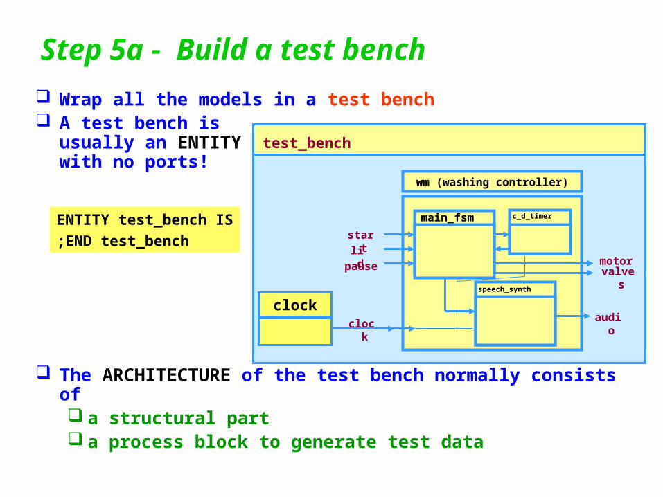
Step 5a - Build a test bench
Wrap all the models in a test bench A test bench is
usually an ENTITYwith no ports!
The ARCHITECTURE of the test bench normally consists of a structural part a process block to generate test data
wm (washing controller)
audio
main_fsm
speech_synth
c_d_timer
motor valves
start
lid
pause
clock
clock
test_bench
ENTITY test_bench IS
END test_bench;
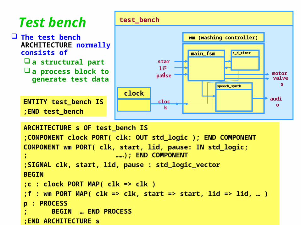
Test bench The test bench
ARCHITECTURE normally consists of a structural part a process block to
generate test data
wm (washing controller)
audio
main_fsm
speech_synth
c_d_timer
motor valves
start
lid
pause
clock
clock
test_bench
ENTITY test_bench IS
END test_bench;
ARCHITECTURE s OF test_bench IS
COMPONENT clock PORT( clk: OUT std_logic ); END COMPONENT;
COMPONENT wm PORT( clk, start, lid, pause: IN std_logic; ……); END COMPONENT;
SIGNAL clk, start, lid, pause : std_logic_vector;
BEGIN
c : clock PORT MAP( clk => clk );
f : wm PORT MAP( clk => clk, start => start, lid => lid, … );
p : PROCESS BEGIN … END PROCESS;
END ARCHITECTURE s;

Test bench
Driving the signals of the component under test For a simple component,
a data flow model with waveform signal assignments may suffice
For our washing machine, we need to check
• Starting, stopping, pausing, opening the lid, …
• So for basic operations, waveforms applied to the control inputs will do:
start <= ‘0’, ‘1’ after 1 sec, ‘0’ after 50 ms -- check starting‘ 1 ’after 10 sec, -- 2nd start should not do anything
‘ 0 ’after 50 ms, ‘1’ after 1000 sec, -- start another test……
lid <= ‘1’, -- start with lid closed
‘ 0 ’after 5 sec, -- open lid after start
‘ 1 ’after 10 sec, -- close again to resume
…

Test bench
Driving the signals of the component under test For a more complex component
(or more complex tests applied to a simple component!)
we’ll generally need to write some loops in PROCESS blocks
PROCESS
BEGIN
FOR j IN 0 TO 9 LOOP – Perform 10 tests
start <= ‘0’; lid <= ‘1’; pause <= ‘0;’
WAIT FOR 1 sec;
-- Now change the control inputs according to some -- table
start <= s(J); lid <= l(j); pause <= p(j);
WAIT FOR t(J);
-- Check result
END LOOP;
END PROCESS;
Assumes thatwe’ve generated
some tables,s(0 TO 9), l(0 TO 9),p(0 TO 9), t(0 TO 9)
containing test data

Step 6 - Verifying the Design
You can check the design by examining simulator waveforms
start
valve
motor
drain
wm (washing controller)
audio
main_fsm
speech_synth
c_d_timer
motor valve (water in)
start
lid
pause
clock
drain (water out)
Note that for this example, we have specifically listed 3 outputs
motor - turns the motor on
valve - opens the water inlet
drain - opens the water outlet
Pulsing the start input should start a washing cyclePulsing it again should not stop the cycle
Cycle starts by opening the inlet valve
After it closes, the motor should start
The motor should stop and the drain openDrain closes, inlet opens.…

Step 6 - Verifying the Design
You can check the design by examining simulator waveforms
start
valve
motor
drain
wm (washing controller)
audio
main_fsm
speech_synth
c_d_timer
motor valve (water in)
start
lid
pause
clock
drain (water out)
We could check everythingby visually examining this
trace...
painful,
manual,
error prone in a large design...
We can do much better!!

State machine outlineENTITY wm IS PORT( clk, start: IN std_logic; motor, valve, drain: OUT std_logic; … );
END ENTITY wm;
ARCHITECTURE a OF wm IS TYPE wm_states IS (off, w_in1, wash, w_out1, w_in2, rinse, .. ); COMPONENT … SIGNAL s : wm_states; BEGIN PROCESS( clk ) BEGIN IF clk’EVENT AND clk = ‘1’ THEN CASE s IS WHEN off => IF start = ‘1’ THEN valve <= ‘1’; -- Open the valve
--More detail on next slide!! END PROCESS;
END ARCHITECTURE wm;
Details not relevant tothis example omitted!

State machine outlineARCHITECTURE a OF wm IS TYPE wm_states IS (off, w_in1, wash, w_out1, w_in2, rinse, .. ); COMPONENT … SIGNAL s : wm_states; BEGIN PROCESS( clk ) BEGIN IF clk’EVENT AND clk = ‘1’ THEN CASE s IS WHEN off => IF start = ‘1’ THEN valve <= ‘1’; -- Open the valve s <= w_in1; … -- start the timer END IF; WHEN w_in1 => IF timer_complete THEN valve <= ‘0’; -- close the valve s <= wash; motor <= ‘1’; … -- start the timer END IF; WHEN wash => … -- and a lot more follows! END CASE; END PROCESS;
END ARCHITECTURE wm;
To keep it simple:A lot of detail ismissing from this model!

Verifying the Design
Looking at thewaveforms again,what things can youobserve that are (should!!)always be true??
start
valve
motor
drain
wm (washing controller)
audio
main_fsm
speech_synth
c_d_timer
motor valve (water in)
start
lid
pause
clock
drain (water out)

Verifying the Design
Looking at thewaveforms again,what things can youobserve that are (should!!)always be true??
start
valve
motor
drain
wm (washing controller)
audio
main_fsm
speech_synth
c_d_timer
motor valve (water in)
start
lid
pause
clock
drain (water out)
Only one of valve, motor or drain is ‘1’ at any time!
So we can add an ASSERT to the model!
ASSERT ((valve OR motor OR drain) = ‘0’) OR (valve=‘1’ AND motor=‘0’ AND drain=‘0’) OR … REPORT “Two outputs ON” SEVERITY warning;

Verifying the Design
These are not the only assertionsthat can be madeabout this design! What are some
others?Hint: Look at someof the other signals!
start
valve
motor
drain
wm (washing controller)
audio
main_fsm
speech_synth
c_d_timer
motor valve (water in)
start
lid
pause
clock
drain (water out)

Adding the assertionsARCHITECTURE a OF wm IS TYPE wm_states IS (off, w_in1, wash, w_out1, w_in2, rinse, .. ); COMPONENT … SIGNAL s : wm_states; BEGIN PROCESS( clk ) BEGIN IF clk’EVENT AND clk = ‘1’ THEN CASE s IS WHEN off => IF start = ‘1’ THEN valve <= ‘1’; -- Open the valve s <= w_in1; … -- start the timer END IF; WHEN w_in1 => … -- and a lot more follows! END CASE; END PROCESS; ASSERT ((motor=‘0’) OR (valve=‘0’) OR (drain=‘0’)) OR … REPORT … SEVERITY …; ASSERT ((lid=‘0’) AND (motor=‘0’)) REPORT … SEVERITY …;END ARCHITECTURE wm;
Unfortunately, the compiler willreject this assertion if you write itjust like this!
motor, valve and drain are declaredOUT and strictly cannot be ‘read’ here!
A simple `work-around’ solves this problem

Adding the assertionsARCHITECTURE a OF wm IS TYPE wm_states IS (off, w_in1, wash, w_out1, w_in2, rinse, .. ); COMPONENT … SIGNAL s : wm_states; SIGNAL motor_i, valve_i, drain_i : std_logic; BEGIN PROCESS( clk ) BEGIN IF clk’EVENT AND clk = ‘1’ THEN CASE s IS WHEN off => IF start = ‘1’ THEN valve_i <= ‘1’; -- Open the valve s <= w_in1; … -- start the timer END IF; WHEN w_in1 => … -- and a lot more follows! END CASE; END PROCESS; ASSERT ((motor_i=‘0’) OR (valve_i=‘0’) OR (drain_i=‘0’)) OR … REPORT … SEVERITY …; ASSERT ((lid=‘0’) AND (motor_i=‘0’)) REPORT … SEVERITY …; motor <= motor_i; valve <= valve_i; drain <= drain_i;END ARCHITECTURE wm;
Add internal signals, which are set bythe state machine …As internal signals, they can be read
Assign them to the actual outputsin the body of the architecture!

Adding the assertions
Because of this minor complication,some might prefer to add the ASSERT’s to the test bench The outputs of the module under test can be read in the test bench! I would prefer to add them to the module itself -
This ensures that they are active in ALL test benches We might write several test benches to test various aspects of a design!
but, this is a personal preference
The important thing is to have them somewhere!! They make your model self-checking Automatic checking is more robust than manual checking!

Alternative verification strategies
When the outputs are complex functions of the inputs, assertions may become either incredibly complex
and thus difficult to code (and get right!) impossible
because of the complex logic required
PROCESS blocks may always be added to the test bench to check that the outputs are correct They can contain arbitrarily complex code -
and can thus check complex conditions Automated checking of models VHDL is just like a programming language
Test benches can write log files, dump data to disc files, etc These files can be checked mechanically by other programs
Use the test bench to automate testing!! Use ASSERT or algorithmic code in PROCESS blocks Automatic checking is more robust than manual checking!
You can also writeVHDL functions
to simplify ASSERT conditions!