Embed Size (px)
Citation preview
BLRBAC RECOMMENDED GOOD PRACTICE April 2013Draft April 2015
Thermal Oxidation of Waste Streams in Black Liquor Recovery Boilers
Page 0
Recommended Guidelines for the Incineration of Waste Streams in Black
Liquor Recovery Boilers.
Proposed Changes In this proposed revision, there are numerous changes to chapter five. The changes are summarized on the following page and the revised sections are referenced as well as the corresponding page number of the changes to each section (in this version of the document). There are also changes in chapter four, but we are still in the process of editing that chapter and we are not ready for chapter four comments at this time. We are asking that the Executive committee review and comment on the changes in chapter five only. There are many small changes that are grammatical in nature or improve readability of the document. These changes are not found in the index page, but are highlighted throughout chapter 5. Note: There are still red additions on figures, 7, 8, 9, and 10 referencing “stably firing liquor”. These were approved in 2013 and have not been changed. Comments and/or questions should be sent to: Paul Seefeld, Chairman, Waste Streams A.H. Lundberg Assoc., Inc. (904)614-6492 [email protected] Submitted Date:
BLRBAC RECOMMENDED GOOD PRACTICE April 2013Draft April 2015
Thermal Oxidation of Waste Streams in Black Liquor Recovery Boilers
Page 1
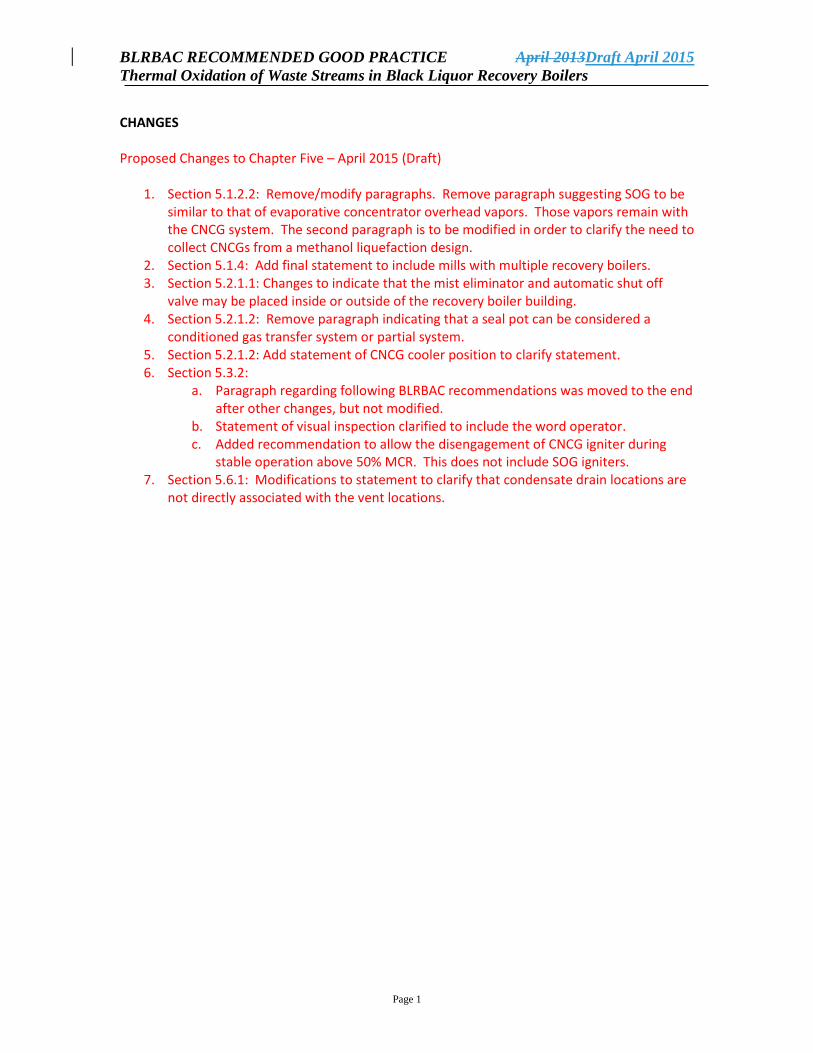
CHANGES Proposed Changes to Chapter Five – April 2015 (Draft)
1. Section 5.1.2.2: Remove/modify paragraphs. Remove paragraph suggesting SOG to be similar to that of evaporative concentrator overhead vapors. Those vapors remain with the CNCG system. The second paragraph is to be modified in order to clarify the need to collect CNCGs from a methanol liquefaction design.
2. Section 5.1.4: Add final statement to include mills with multiple recovery boilers. 3. Section 5.2.1.1: Changes to indicate that the mist eliminator and automatic shut off
valve may be placed inside or outside of the recovery boiler building. 4. Section 5.2.1.2: Remove paragraph indicating that a seal pot can be considered a
conditioned gas transfer system or partial system. 5. Section 5.2.1.2: Add statement of CNCG cooler position to clarify statement. 6. Section 5.3.2:
a. Paragraph regarding following BLRBAC recommendations was moved to the end after other changes, but not modified.
b. Statement of visual inspection clarified to include the word operator. c. Added recommendation to allow the disengagement of CNCG igniter during
stable operation above 50% MCR. This does not include SOG igniters. 7. Section 5.6.1: Modifications to statement to clarify that condensate drain locations are
not directly associated with the vent locations.
BLRBAC RECOMMENDED GOOD PRACTICE April 2013Draft April 2015
Thermal Oxidation of Waste Streams in Black Liquor Recovery Boilers
Page 2
1.
RECOMMENDED GOOD PRACTICE
THERMAL OXIDATION OF WASTE STREAMS
IN
BLACK LIQUOR RECOVERY BOILERS
THE BLACK LIQUOR RECOVERY BOILER ADVISORY COMMITTEE
April 2013
BLRBAC RECOMMENDED GOOD PRACTICE April 2013Draft April 2015
Thermal Oxidation of Waste Streams in Black Liquor Recovery Boilers
Page 3
CHAPTER 5 GUIDELINES FOR THERMAL OXIDATION OF CNCG AND SOG
5.1 Introduction
This Recommended Good Practice presents the use of the recovery boiler as the control
device for thermal oxidation of CNCG and SOG.
5.1.1 Safety
During the thermal oxidation of CNCG and SOG, the safety hazards for both personnel
and equipment have to be considered.
The equipment for thermal oxidation as well as collection and treatment of CNCG should
be designed and controlled such that:
CNCG cannot escape into the recovery boiler building area.
Condensate cannot carry into the recovery boiler.
Fire and explosion in equipment and pipe systems is prevented.
Positive ignition of gases entering the furnace is provided.
In no case shall the safety requirements be less restrictive than those presented in the
following BLRBAC publications:
Recommended Good Practice for the Safe Firing of Auxiliary Fuel in Black Liquor
Recovery Boilers.
Recommended Good Practice for the Safe Firing of Black Liquor in Black Liquor
Recovery Boilers.
BLRBAC Recommended Rules for Personnel Safety for Black Liquor Recovery
Boilers.
Instrumentation Checklist and Classification Guide for Instruments and Control
Systems Used in Operation of Black Liquor Recovery Boilers.
5.1.2 Sources
5.1.2.1 CNCG
The main sources of concentrated noncondensible gases (CNCG) are:
Noncondensible gases from black liquor evaporation
Vents from foul condensate tank, turpentine decanter, turpentine tank, methanol tank
and various pumping tanks.
Vents from flash tanks, condensers and specialty process equipment--these need to be
evaluated on an individual basis concerning classification as a dilute or concentrated
NCG. The digester chip bin vent gases cannot be included in the CNCG system
because of high air content.
BLRBAC RECOMMENDED GOOD PRACTICE April 2013Draft April 2015
Thermal Oxidation of Waste Streams in Black Liquor Recovery Boilers
Page 4
5.1.2.2 SOG
SOG from a foul condensate steam stripper is handled in a separate and independent
system for introduction into the recovery furnace for thermal oxidation. These gases
generally are the gas product from the stripper reflux condenser and reflux tank, and
consist principally of water vapor, methanol, reduced sulfur components and potentially
small amounts of turpentine and other hydrocarbons. An additional process step is
incorporated in some mills to condense the methanol from the gases and handle the
methanol liquid stream separately.
Vents from a high solids concentrator system are similar in nature to the SOG from a
stripper column and should be handled in a gas system similar in design to that used for
SOG. The system should be independent of other NCG systems from the source to and
including the burner gun.
As an option, SOG can be modified by removing its methanol content. The remaining gas
is a low volume CNCG. When liquefying the SOG stream, there will be a residual
CNCG component that will need to be collected as part of the CNCG system.
5.1.3 Dedicated Burner
A dedicated burner should be used for thermal oxidation of CNCG and SOG in the
recovery boiler. The burner should be equipped with an NFPA Class 1 continuous igniter
and igniter flame scanner. This arrangement will provide more stable and safer firing of
the gases than arrangements that depend on the heat from black liquor combustion to
sustain the thermal oxidation of the NCG. This arrangement further considers that there is
not a reliable means of detecting a loss of black liquor flame to shut off the NCG flows to
the recovery boiler.
5.1.4 The Recovery Boiler as Primary Control Device
When the recovery boiler is used, it should be the primary control device. In the recovery
boiler the sulfur compounds in the NCG are captured back into the process. When the
recovery boiler is the primary control device, the effect of the NCG on the recovery
boiler sodium-sulfur balance will be constant. This balance would be changing will
change if the recovery boiler were is used as a secondary control device with the NCG
being thermally oxidized in the boiler intermittently, or if a single recovery boiler is used
at a facility with multiple recovery boilers.
5.2 Collection and Transfer of CNCG and SOG
A thorough sampling and evaluation study of all components of the CNCG and SOG
should be performed to determine temperature, volumetric flow, moisture content and
percentage UEL of each individual source. That study should include both normal steady
state operation and maximum rate with upset conditions. This data should be used by a
BLRBAC RECOMMENDED GOOD PRACTICE April 2013Draft April 2015
Thermal Oxidation of Waste Streams in Black Liquor Recovery Boilers
Page 5
qualified specialist to determine the operating condition and properties of the combined
CNCG streams and the SOG stream at the recovery boiler.
Consider locating motive equipment for collecting gases and the diversion system in an
area outside the recovery boiler area so they can be accessed even at times when the
recovery boiler area is evacuated. Where facilities are subject to winter climates with
temperatures below freezing, consideration should be given to locating the equipment in
a warm enclosure. Control of the system should be from the recovery boiler control room.
The engineer should give highest piority to the selection of the ejector and other control
components to maximize the best control and safety of the CNCG system.
5.2.1 CNCG
The sources of gases connected to the CNCG system must be of such nature that air
cannot enter the system.
The CNCG from the common collection point to the waste streams burner can be handled
in two different ways.
Vapor phase transfer system (no gas conditioning involving any change in component
concentration)
Conditioned gas transfer system
5.2.1.1 Vapor Phase Transfer System
After the common collection point the gases are moved by means of a steam ejector or
water ring blower directly to the waste streams burner system. No conditioning involving
any change in component concentration is done.
The piping system starting at the steam ejector (water ring blower) typically includes the
following equipment.
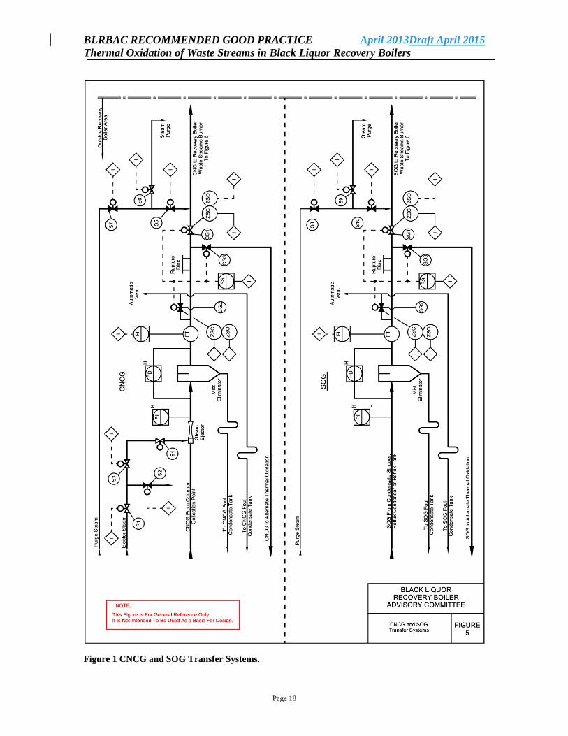
Figure 5 - Equipment Outside the Recovery Boiler Area
Steam ejector or water ring blower
Pressure transmitter for monitoring with high and low alarms located after the steam
ejector (water ring blower)
Mist eliminator(s) (with pressure drop monitoring and high pressure drop alarm)*
Flow transmitter with interlock function
Main header vent line with automatic valve, drain function included
Recovery boiler line automatic shut-off valve*
Tie-in to alternate thermal oxidation device (optional)
Steam purge connection
Figure 6 - Equipment Inside the Recovery Boiler Area
BLRBAC RECOMMENDED GOOD PRACTICE April 2013Draft April 2015
Thermal Oxidation of Waste Streams in Black Liquor Recovery Boilers
Page 6
Recovery boiler vent line with automatic valve, drain function included
Automatic double block and bleed valves (located close to burner)
Mist eliminator(s) (with pressure drop monitoring and high pressure drop alarm)*
Recovery boiler line automatic shut-off valve*
Pressure and temperature switches/transmitters for interlock functions located before
the automatic double block and bleed valves
Flame arresters or detonation arresters (with pressure drop monitoring and high
pressure drop alarm) located as close to the burner as possible.
Items with an (*) may be placed inside or outside the recovery boiler area, depending
upon the final piping design.
The following equipment will be located in the system as required.
Pressure relief devices such as rupture disk(s)
Low point drains
Steam heat tracing and /or indirect steam preheater (not shown in figures)
The intent of the design for the system is to ensure that no condensates of the condensible
components--methanol, water or turpentine--can collect and cause upsets to the waste
streams burner system or the recovery boiler. The CNCG piping should be heavily
insulated from the source to the waste streams burner to minimize condensation
formation in the line. Depending on local conditions, heat tracing may be considered.
5.2.1.2 Conditioned Gas Transfer System
The following components are included in addition to those used in a vapor phase
transfer system.
Gas cooler / condenser
Indirect steam preheater with auxiliaries
A concentrated NCG system with a seal pot is considered to be a conditioned gas transfer
system. The seal pot is used to isolate lines and prevent flashback. It will act as a quench
cooler and thereby will perform partial condensation.
The intent of the Conditioned Gas Transfer System is to reduce the amount of water
vapor and condensible gases and increase thermal efficiency by reducing the loss due to
water vapor. The condensate would be typically transferred to a foul condensate
treatment system which may include a steam stripper.
The gas analysis needs to be carefully evaluated before and after the condenser with
regard to explosion range and combustion characteristics to determine the impact of
conditioning on the gas. Condensing of large amounts of water vapor, methanol and
turpentine may shift the resulting gas mixture into the explosive range depending on the
BLRBAC RECOMMENDED GOOD PRACTICE April 2013Draft April 2015
Thermal Oxidation of Waste Streams in Black Liquor Recovery Boilers
Page 7
residual amount of infiltration air and the combustible gas concentrations. The heating
value and combustion characteristics may also be changed due to condensing of
turpentine and methanol.
When the CNCG cooler is located downstream of the steam ejector, Iit is recommended
to heat the gas after the cooler and/or heat trace the down stream piping to raise the
operating temperature of the gas burner system to well above the dewpoint and thereby
protect it from upsets due to condensates.
5.2.2 SOG
SOG is primarily a mixture of TRS compounds, methanol and steam at saturated steam
conditions that can be hotter than other CNCG. Frequently, the pressure of the gas at the
stripper condenser discharge is much higher than that of other CNCG streams. The SOG
must be handled in lines separate from the other CNCG to prevent condensation of the
SOG constituents in the collection system and to handle the differences in pressure. The
SOG handling system does not provide conditioning involving any change in component
concentration with the exception of a stripper system where methanol is may be
condensed and recovered transferred as a liquid.
Upset conditions caused by black liquor carryover or evaporator boilout can result in
generating foam in the condensate stripper. This foam can then be transported with the
SOG to the recovery furnace. Provisions must be made to prevent foam carryover into the
SOG to preclude introducing foam into the furnace.
The SOG piping should be heavily insulated from the source to the waste streams burner
to minimize condensation formation in the line. Steam tracing of the stripper off-gas
piping should be considered in cold climates.
If the stripper off-gases at the source are at an adequate pressure to provide the motive
force to transport them to the waste streams burner, then the piping system leading to the
burner typically would include the following equipment. This arrangement would also
apply to CNCG from a high solids concentrator.
Figure 5 - Equipment Outside the Recovery Boiler Area
Pressure transmitter for monitoring with high and low alarms
Mist eliminator(s) (with pressure drop monitoring)
Flow transmitter with interlock function
Main header vent line with automatic valve, drain function included
Recovery boiler line automatic shut-off valve
Tie-in to alternate thermal oxidation point (optional)
Steam purge connection
Figure 6 - Equipment Inside the Recovery Boiler Area
BLRBAC RECOMMENDED GOOD PRACTICE April 2013Draft April 2015
Thermal Oxidation of Waste Streams in Black Liquor Recovery Boilers
Page 8
Recovery boiler vent line with automatic valve, drain function included
Automatic double block and bleed valves (located close to burner)
Pressure and temperature switches for interlock functions located before the
automatic double block and bleed valves.
Monitoring pressure and temperature transmitters with high and low alarms located
before the automatic double block and bleed valves.
Flame arresters or detonator arresters (with pressure drop monitoring and high
pressure drop alarm) located as close to the burner as possible.
The following equipment will be located in the system as required.
Pressure relief devices such as rupture disk(s)
Low point drains
Heat tracing and/or indirect steam preheater (not shown in figures)
If the SOG at the source are is not at an adequate pressure to provide the motive force to
transport it to the waste streams burner, then the piping system leading to the burner
typically would include the previously mentioned equipment and a steam ejector.
5.2.3 CNCG and SOG Piping System and Auxiliary Equipment
CNCG and SOG should be handled in completely independent collection systems due to
temperature and pressure differences between the two streams being handled. There is a
risk of condensing methanol from SOG with the cooler CNCG stream.
Due to system pressure differentials, it is recommended that the SOG system and CNCG
system not share any common auxiliary equipment such as condensate collection vessels.
There is a risk of one system discharging into the other.
The piping system and steam ejector or water ring blower should be sized so that
minimum transport velocities for gases are maintained.
Gas piping should be designed to prevent accumulation of condensate and should be
designed with the shortest possible pipe run inside the recovery boiler building. The
piping should not be routed close to critical areas such as the dissolving tank or the
corners of the furnace or near areas likely to be occupied by personnel such as normal
accessways.
CNCG and SOG should be securely isolated when shutting down the thermal oxidation
system, therefore valves in the system should be chosen carefully with attention given to
shutoff classifications. Automatic valves should have position switches to confirm valve
position status.
Piping downstream of the mist eliminator should be insulated and heat traced to prevent
condensate formation in the line. Consideration should be given to sloping the piping in
the direction of gas flow for drainage rather than having horizontal lines. This avoids the
BLRBAC RECOMMENDED GOOD PRACTICE April 2013Draft April 2015
Thermal Oxidation of Waste Streams in Black Liquor Recovery Boilers
Page 9
accumulation of a quantity of water, which could be suddenly released into the furnace as
well as the likelihood of accumulating flammable organic deposits. The designer should
proceed on the basis that there will be condensate in the pipe from time to time and that it
must be removed.
Each vent line should have one shut-off valve with “fail open” actuator that will open
automatically when waste stream firing to the recovery boiler is stopped.
Each gas line to the recovery boiler should have a flame arrester. There should be a
differential pressure tranmitter across the flame arrester to alarm high differential
pressure. Provision can be made to clean the flame arrester using steam or inert gas.
Any water or steam connections to the system should have double block and bleed valves
or removeable spool pieces per BLRBAC Recommended Good Practice for Safe Firing
of Black Liquor in Black Liquor Recovery Boilers. Automatic valves should have
position switches to confirm valves position status. Steam piping should be properly
designed and trapped to prevent condensate collection. Air should not be used as a
purge medium due to the possible risk of creating an explosive gas mixture.
If a seal pot (for isolation and flashback prevention) is used, it should be constructed and
controlled so that water cannot carry into the recovery boiler through the waste stream
line. Therefore there should be two (2) independent protective systems such as switches
with alarm and interlock functions. It is imperative that the seal pot not overflow into the
CNCG transport line to the recovery boiler.
The condensate collection system should be designed so that it cannot be pressurized
causing condensate to back flow to the transport line. As an example, an overflow to a
closed sewer system could cause pressurization.
Drains in the system are prone to plugging and should be of a size to reduce that
possibility, with consideration given to at least 1-1/2” drain lines.
Materials of construction for ductwork, piping and equipment in contact with CNCG and
SOG should be AISI type 304L or 316L stainless steel, or other metals with equivalent or
better corrosion resistant and strength properties.
Material containing iron that might turn into FeS in contact with NCG should not be
used. Under certain conditions in the presence of air, FeS can oxidize and create heat
with explosions or fire as a result.
The system designer must take into account the movement of the waste streams burner
due to the expansion of the furnace, and make sure that the movement does not induce
unacceptable stresses in the piping.
Piping must meet the required service conditions and be acceptable to the authorities
which may have jurisdiction.
BLRBAC RECOMMENDED GOOD PRACTICE April 2013Draft April 2015
Thermal Oxidation of Waste Streams in Black Liquor Recovery Boilers
Page 10
5.3 Thermal Oxidation
5.3.1 Burner
The waste stream burner(s) should be mechanically suited for installation and operation
in a recovery boiler.
The waste stream burner(s) should have a dedicated air system. The combustion air can
be supplied from a separate fan or from the recovery boiler secondary air or tertiary air
fan. Proof of adequate combustion air flow is required as proven by a flow switch or
other suitable means.
CNCG and SOG should be conveyed to the burner through independent lines and
injected into the flame zone separately. A separate system to feed fuel to the continuous
igniter is required.
The burner should be placed in the high heat zone of the furnace at or below the tertiary
air level. It should be placed in such a manner that disturbances in the continuous flame
of the igniter are avoided so as to not create difficulty with detection.
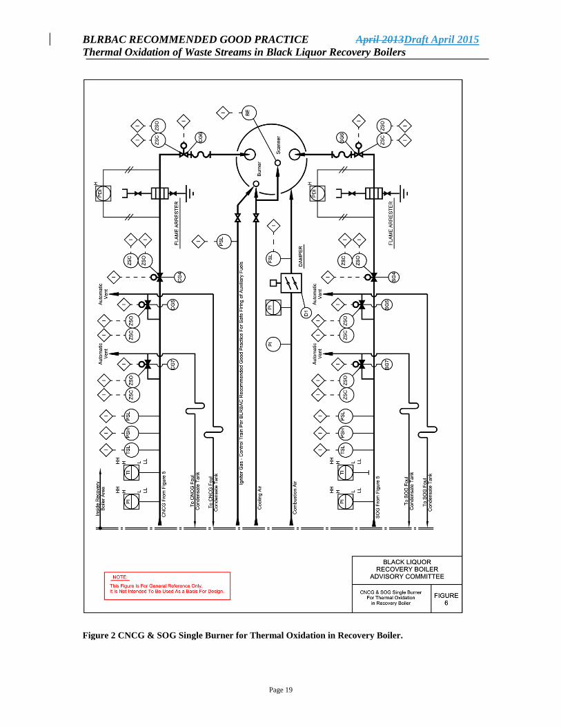
Example of equipment for monitoring and controlling a single burner installation for
CNCG and SOG is shown in Figure 6. Multiple burner installations should follow
multiple burner standards.
When the NCG system is down, the second automatic shut-off valve should be locked in
the closed position. The connections in the CNCG and SOG piping downstream of the
shut off valve at the gun should be designed and installed to allow ease of maintenance
and inspection on a routine basis.
Cooling of a CNCG/SOG nozzle that is not in use can not be accomplished by injection
of air into the CNCG/SOG nozzle.
5.3.2 Continuous Igniter
An NFPA Class 1 igniter (NFPA 8501) is a key element in the thermal oxidation of
CNCG and SOG. The capacity of the igniter should be large enough to provide safe
ignition and be at least 10 percent of the maximum energy release of the gases being
thermally oxidized. The igniter shall be continuous. The igniter should have proof of
adequate ignition energy using a low pressure switch on the igniter fuel header.
The igniter can have a common air duct with the burner for CNCG and SOG. Air feed to
the igniter should provide stable ignition and operating conditions.
The oil or gas system to the igniter as well as flame monitoring should, in all aspects,
follow the BLRBAC Recommended Good Practice for Safe Firing of Auxiliary Fuel.
BLRBAC RECOMMENDED GOOD PRACTICE April 2013Draft April 2015
Thermal Oxidation of Waste Streams in Black Liquor Recovery Boilers
Page 11
Light-off of the igniter must be initiated at the burner front, and then only after an
operator visually inspects inspecting the burner opening in the furnace wall to ensure that
there is no plugging.
If the boiler is above 50% MCR and CNCG has been safely introduced, the igniter may
be disengaged. SOG incineration should still use a continuous igniter.
The oil or gas system to the igniter as well as flame monitoring should, in all aspects,
follow the BLRBAC Recommended Good Practice for Safe Firing of Auxiliary Fuel.
5.3.3 Combustion Air
The recovery boiler secondary or tertiary air fan can be used. If the combustion air is
supplied by the secondary air fan, a booster fan may be necessary to provide minimum air
pressure to the waste stream burner. The system design should be such that uninterrupted
air flow to the recovery boiler for black liquor combustion is first priority.
The following instrumentation for monitoring and control of combustion air should be
provided.
Local pressure indicator
Suitable means for proving adequate air flow
Indicating pressure transmitter
Booster fan running--signal from motor starter, speed switch, etc.
5.4 Safety System
The waste streams burner should have a flame safety system complying with the
BLRBAC Recommended Good Practice for the Safe Firing of Auxiliary Fuel. The
system design should comply with NFPA standards and insurance carrier
recommendations. The waste streams burner flame safety system can be integrated with
the auxiliary fuel’s burner management system or can be stand-alone.
The permissive starting logic and protective tripping logic contain the logic of Safe Firing
of Auxiliary Fuel plus additional requirements. The additional requirements pertain to the
quality of the NCG.
Care must be taken to never allow the waste streams burner to maintain purge credit. In
other words, the waste streams burner cannot be counted as an auxiliary fuel burner when
the burner management system checks if there is an auxiliary burner in service.
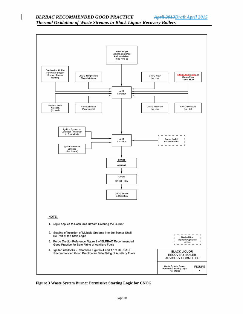
5.4.1 Permissive Starting Logic - CNCG
To start thermal oxidation of CNCG in the waste streams burner the following conditions
must be fulfilled.
BLRBAC RECOMMENDED GOOD PRACTICE April 2013Draft April 2015
Thermal Oxidation of Waste Streams in Black Liquor Recovery Boilers
Page 12
Purge credit established and maintained
Firing liquor stably or steam flow greater than 50% of the steam flow at MCR
Combustion air fan for waste streams burner running
Combustion air flow normal
CNCG flow (velocity) above minimum
CNCG temperature above minimum
CNCG pressure not high
CNCG pressure not low
Seal pot level not high (if used)
Burner switch in START position
Igniter has been in stable operation for minimum one minute
Igniter interlocks satisfied
Staging of injection of multiple streams into a waste stream burner should be part of the
Start Permissives.
Permissive Starting Logic for thermal oxidation of CNCG in the waste streams burner is
shown in Figure 7.
5.4.2 Protective Tripping Logic - CNCG
Any of the following conditions will cause the waste streams burner to shut down thermal
oxidation of CNCG.
Master Fuel Trip (purge credit lost)
Not firing liquor stably or steam flow less than 50% of steam flow at MCR
CNCG pressure high
CNCG pressure low
Combustion air fan for waste streams burner off
CNCG temperature below minimum
CNCG flow (velocity) below minimum
Combustion air flow not normal
Igniter interlocks not satisfied
Burner switch in STOP position
Seal pot level high (if used)
Protective Tripping Logic for thermal oxidation of CNCG in the waste streams burner is
shown in Figure 8.
5.4.3 Permissive Starting Logic - SOG
To start thermal oxidation of SOG in the waste streams burner the following conditions
must be fulfilled.
BLRBAC RECOMMENDED GOOD PRACTICE April 2013Draft April 2015
Thermal Oxidation of Waste Streams in Black Liquor Recovery Boilers
Page 13
Purge credit established and maintained
Firing liquor stably or steam flow greater than 50% of the steam flow at MCR
Combustion air fan for waste streams burner running
Combustion air flow normal
SOG flow (velocity) above minimum
SOG temperature above minimum
SOG pressure not high
SOG pressure not low
Seal pot level not high (if used)
Burner switch in START position
Igniter has been in stable operation for a minimum of one minute
Igniter interlocks satisfied
Permissive Starting Logic for thermal oxidation of SOG in the waste streams burner is
shown in Figure 9.
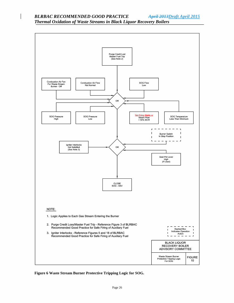
5.4.4 Protective Tripping Logic - SOG
Any of the following conditions will cause the waste streams burner to shut down thermal
oxidation of SOG.
Master Fuel Trip (purge credit lost)
Not firing liquor stably or steam flow less than 50% of steam flow at MCR
SOG pressure high
SOG pressure low
Combustion air fan for waste streams burner off
SOG temperature below minimum
SOG flow (velocity) below minimum
Combustion air flow not normal
Igniter interlocks not satisfied
Burner switch in STOP position
Seal pot level high (if used)
Protective tripping logic for thermal oxidation of SOG in the waste streams burner is
shown in Figure 10.
5.5 Personnel Safety
Operational problems, which have to do with collecting, treatment and destruction of
CNCG can lead to accidents and serious injury.
CNCG contain among other things, H2S , organic sulfides and methanol, and at certain
times, even high level of turpentine. In addition to the health risk, there is also a risk of a
gas explosion.
BLRBAC RECOMMENDED GOOD PRACTICE April 2013Draft April 2015
Thermal Oxidation of Waste Streams in Black Liquor Recovery Boilers
Page 14
Regarding the risks with hazardous compounds present in CNCG and SOG, see OSHA
Guidelines concerning these compounds.
Areas containing NCG piping and equipment should be monitored in accordance with
applicable safety codes.
Daily inspection and control is needed to check for leaks in systems for CNCGs and
SOGs. Leaks in the system should be corrected immediately.
5.6 System Description and Operation
This section is included to illustrate the application of Chapter 5 guidelines. It is for
information purposes only and is not to be considered as additional guidelines.
The arrangement of piping and equipment as shown on the flow sheets (Figures 5 and 6)
are the same for both CNCG and SOG. For the purposes of this discussion, the CNCG
system is used.
5.6.1 Description
Steam to the gas transport steam ejector has a double block and bleed valve arrangement
consisting of valves S1, S2 and S3. This steam connection and other steam connections
on Figures 5 and 6 are shown with double block valves and a bleed (or “free blow”) valve
because they are potential sources of water injection into the furnace. The double block
and bleed valve set provides secure sealing plus, with proper sequencing of valve
opening, collected condensate can be blown out the bleed line before steam is routed to
the gas line.
Downstream of the steam ejector and outside the recovery boiler area, the CNCG line
will have a vent to atmosphere controlled by an automated shutoff valve, CG2. Following
this vent connection there is an automated valve, CG1, which isolates the branch line to
the recovery boiler. If required, there can be a tee ahead of CG1. The tee will allow the
gas to be transported to an alternate thermal oxidizer through valve CG3.
It is important that valves CG1, CG2 and CG3 be located outside of the recovery boiler
area or in the case of indoor installations in a “designated safe area” so that they are
accessible at all times, even in the event of an ESP. Being located outside of the recovery
boiler area does not preclude the valves from being in another building.
Immediately downstream of valve CG1 is an automated steam connection consisting of
valves S5, S6 and S7. It purges and preheats the next “leg” of CNCG line.
Located immediately before valve CG4 is a line size vent isolated by valve CG7. This
vent line serves the CNCG line from valve CG1 to valve CG4. It is used for steam
preheating, CNCG venting in anticipation of CNCG firing, and purging after ceasing
BLRBAC RECOMMENDED GOOD PRACTICE April 2013Draft April 2015
Thermal Oxidation of Waste Streams in Black Liquor Recovery Boilers
Page 15
CNCG firing. The steam for preheating and purging is supplied by the previously
mentioned valves S5, S6 and S7.
The vent discharges to the outside of the boiler area. Both this vent and the previously
mentioned vent controlled by valve CG2 must be above roofs and away from air intakes.
The outlets of these vents must be arranged in such a way that ice plugs are avoided.
A condensate drain from the CNCG line must be included at both vent locations to ensure
removal of liquid that is swept along by the venting gases. The drain function can be
included with the vent, or two connections can be used; one to vent and the other to drain
the line.
A CNCG line double block and bleed valve arrangement represented by valves CG4,
CG5 and CG6 provides the final isolation of CNCG from the furnace. The “bleed”, CG5,
must be designed so that vapor can be vented from the isolated portion of CNCG line
while liquid is vented drained fromout of the bottom of the line. Valve CG5 could be two
valves, one for venting and the other for draining. The vent from CG5 can be connected
to the main vent on the discharge of valve CG7.
The CG4, CG5 and CG6 valve set must be located as close to the burner as possible to
minimize the retained CNCG volume from these isolation valves to the burner.
If the volume of CNCG that is retained is small and the piping system has the mechanical
integrity to sustain a burn back after the isolation valves shut, then purging of the piping
from the isolation valves to the burner is not necessary. Not purging the line avoids the
possibility of water introduction to the furnace if steam is used for purging.
There are, however, system designs and maintenance safety issues that make purging of
this piping run an attractive consideration; for example, large CNCG systems that have a
substantial volumetric capacity in this last piping leg. Section 5.2.3, Piping System and
Auxiliary Equipment, discusses line sloping, steam supply requirements, and insulating
and heat tracing waste gas lines. An important part of this concept is the use of a burner
design that is drainable, that is, a burner that cannot retain liquid. The purge must be done
immediately after firing the CNCG system is terminated, while the piping is still hot, and
with the igniter in service.
If steam purging is used, special attention must be given to keeping the steam free of
condensate, thus avoiding introduction of water into the furnace. A steam line that is only
occasionally used has a high probability of containing condensate and therefore injecting
that condensate into the CNCG piping when the steam line is opened. The system design
and operation must ensure that the purging steam is dry. As an alternative to steam,
another inert gas can be used as a purging medium. For any purging medium (steam or an
inert gas), the purge should displace the volume of gas contained in the piping between
the last isolation valve and the furnace.
BLRBAC RECOMMENDED GOOD PRACTICE April 2013Draft April 2015
Thermal Oxidation of Waste Streams in Black Liquor Recovery Boilers
Page 16
A flame arrester is located in the CNCG line as close to the burner as possible. The flame
arrester physical location must be convenient for isolation and maintenance.
5.6.2 Operation
The CNCG/SOG thermal oxidation system is put into service from a local panel board by
and operator who is in contact with the control room. Discontinuing thermal oxidation
under normal circumstances is also done locally.
The CNCG transport system is put into operation with branch line isolation valve CG1
closed and vent valve CG2 open. At this point the double block and bleed CNCG valves,
CG4, CG5 and CG6, are shut meaning the shutoff valves are closed and the bleed valve
(providing vent and drain service) is open.
Next, the steam purge and preheat valves, S5, S6 and S7, are opened along with the
vent/drain valve(s), CG7. This provides preheating of the CNCG line from the branch
isolation valve outside of the boiler building to the vicinity of the burner. The branch
valve CG1 remains closed. Admission of steam preheats the line and exits through the
vent/drain.
Adequate preheating of the line will be determined by an operator observing the
temperature indicator on the DCS. Once the line between the CG1and CG4 is heated, the
preheat steam is shut off, the branch valve CG1 is opened and vent CG2 is closed
allowing gas to be vented out of the second vent, CG7. Upon satisfying all permissives,
the final gas block and bleed valves are opened, vent CG7 is closed and CNCG gases will
be admitted to the furnace for thermal oxidation.
For a normal shut down, CNCG shutoff valves CG4 and CG6 and branch valve CG1 are
closed, and both vent valves, CG7 and CG2, are opened as is bleed valve CG5. In
addition, steam purge is immediately initiated. After adequate time for thorough purging,
the steam purge is shut off.
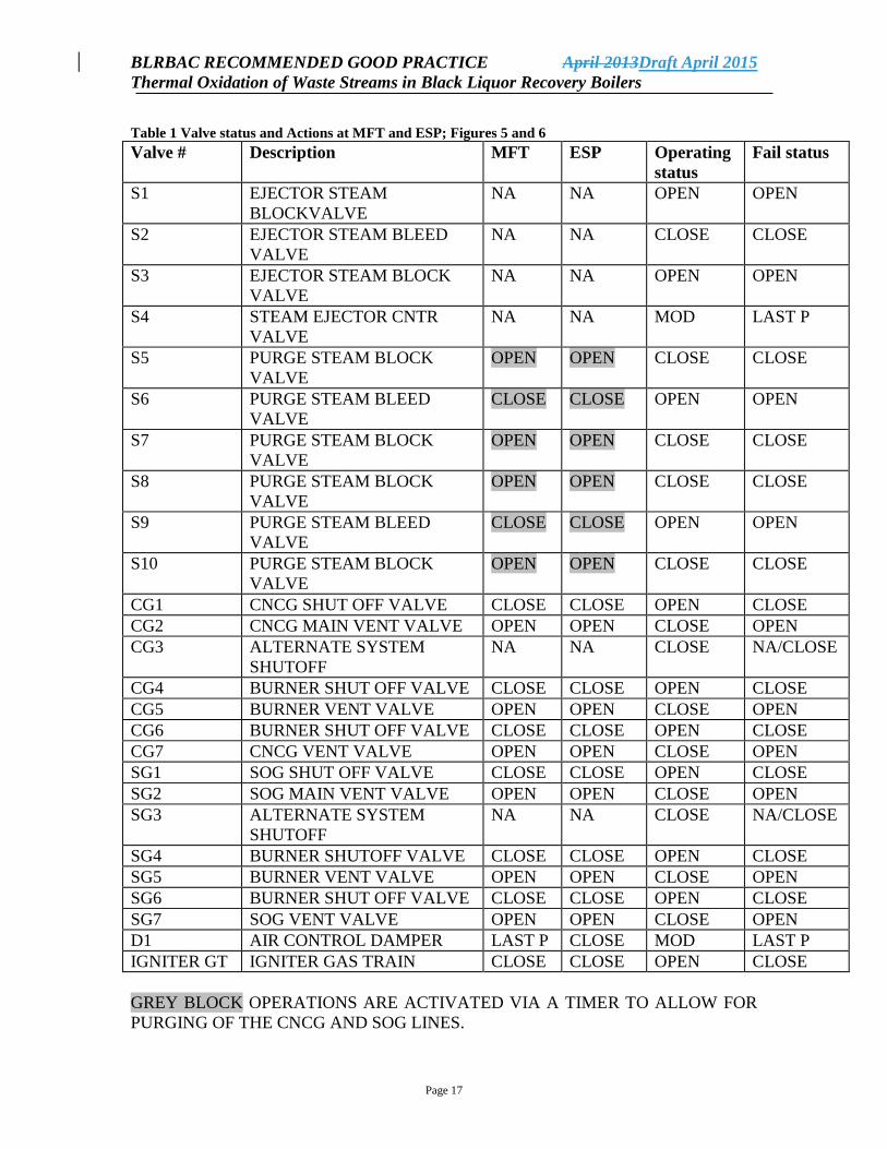
Table 5 shows the actions that constitute a burner shutdown, both MFT and ESP. The
valve positions for “normal operation” and “fail” status are also shown. If an ESP is
activated, a MFT will be exercised as well as isolating all steam and water sources. An
ESP will not initiate automatic purging of the CNCG line to the burner.
BLRBAC RECOMMENDED GOOD PRACTICE April 2013Draft April 2015
Thermal Oxidation of Waste Streams in Black Liquor Recovery Boilers
Page 17
Table 1 Valve status and Actions at MFT and ESP; Figures 5 and 6
Valve # Description MFT ESP Operating
status
Fail status
S1 EJECTOR STEAM
BLOCKVALVE
NA NA OPEN OPEN
S2 EJECTOR STEAM BLEED
VALVE
NA NA CLOSE CLOSE
S3 EJECTOR STEAM BLOCK
VALVE
NA NA OPEN OPEN
S4 STEAM EJECTOR CNTR
VALVE
NA NA MOD LAST P
S5 PURGE STEAM BLOCK
VALVE
OPEN OPEN CLOSE CLOSE
S6 PURGE STEAM BLEED
VALVE
CLOSE CLOSE OPEN OPEN
S7 PURGE STEAM BLOCK
VALVE
OPEN OPEN CLOSE CLOSE
S8 PURGE STEAM BLOCK
VALVE
OPEN OPEN CLOSE CLOSE
S9 PURGE STEAM BLEED
VALVE
CLOSE CLOSE OPEN OPEN
S10 PURGE STEAM BLOCK
VALVE
OPEN OPEN CLOSE CLOSE
CG1 CNCG SHUT OFF VALVE CLOSE CLOSE OPEN CLOSE
CG2 CNCG MAIN VENT VALVE OPEN OPEN CLOSE OPEN
CG3 ALTERNATE SYSTEM
SHUTOFF
NA NA CLOSE NA/CLOSE
CG4 BURNER SHUT OFF VALVE CLOSE CLOSE OPEN CLOSE
CG5 BURNER VENT VALVE OPEN OPEN CLOSE OPEN
CG6 BURNER SHUT OFF VALVE CLOSE CLOSE OPEN CLOSE
CG7 CNCG VENT VALVE OPEN OPEN CLOSE OPEN
SG1 SOG SHUT OFF VALVE CLOSE CLOSE OPEN CLOSE
SG2 SOG MAIN VENT VALVE OPEN OPEN CLOSE OPEN
SG3 ALTERNATE SYSTEM
SHUTOFF
NA NA CLOSE NA/CLOSE
SG4 BURNER SHUTOFF VALVE CLOSE CLOSE OPEN CLOSE
SG5 BURNER VENT VALVE OPEN OPEN CLOSE OPEN
SG6 BURNER SHUT OFF VALVE CLOSE CLOSE OPEN CLOSE
SG7 SOG VENT VALVE OPEN OPEN CLOSE OPEN
D1 AIR CONTROL DAMPER LAST P CLOSE MOD LAST P
IGNITER GT IGNITER GAS TRAIN CLOSE CLOSE OPEN CLOSE
GREY BLOCK OPERATIONS ARE ACTIVATED VIA A TIMER TO ALLOW FOR
PURGING OF THE CNCG AND SOG LINES.
BLRBAC RECOMMENDED GOOD PRACTICE April 2013Draft April 2015
Thermal Oxidation of Waste Streams in Black Liquor Recovery Boilers
Page 18
Figure 1 CNCG and SOG Transfer Systems.
BLRBAC RECOMMENDED GOOD PRACTICE April 2013Draft April 2015
Thermal Oxidation of Waste Streams in Black Liquor Recovery Boilers
Page 19
Figure 2 CNCG & SOG Single Burner for Thermal Oxidation in Recovery Boiler.
BLRBAC RECOMMENDED GOOD PRACTICE April 2013Draft April 2015
Thermal Oxidation of Waste Streams in Black Liquor Recovery Boilers
Page 20
Figure 3 Waste System Burner Permissive Starting Logic for CNCG
BLRBAC RECOMMENDED GOOD PRACTICE April 2013Draft April 2015
Thermal Oxidation of Waste Streams in Black Liquor Recovery Boilers
Page 21
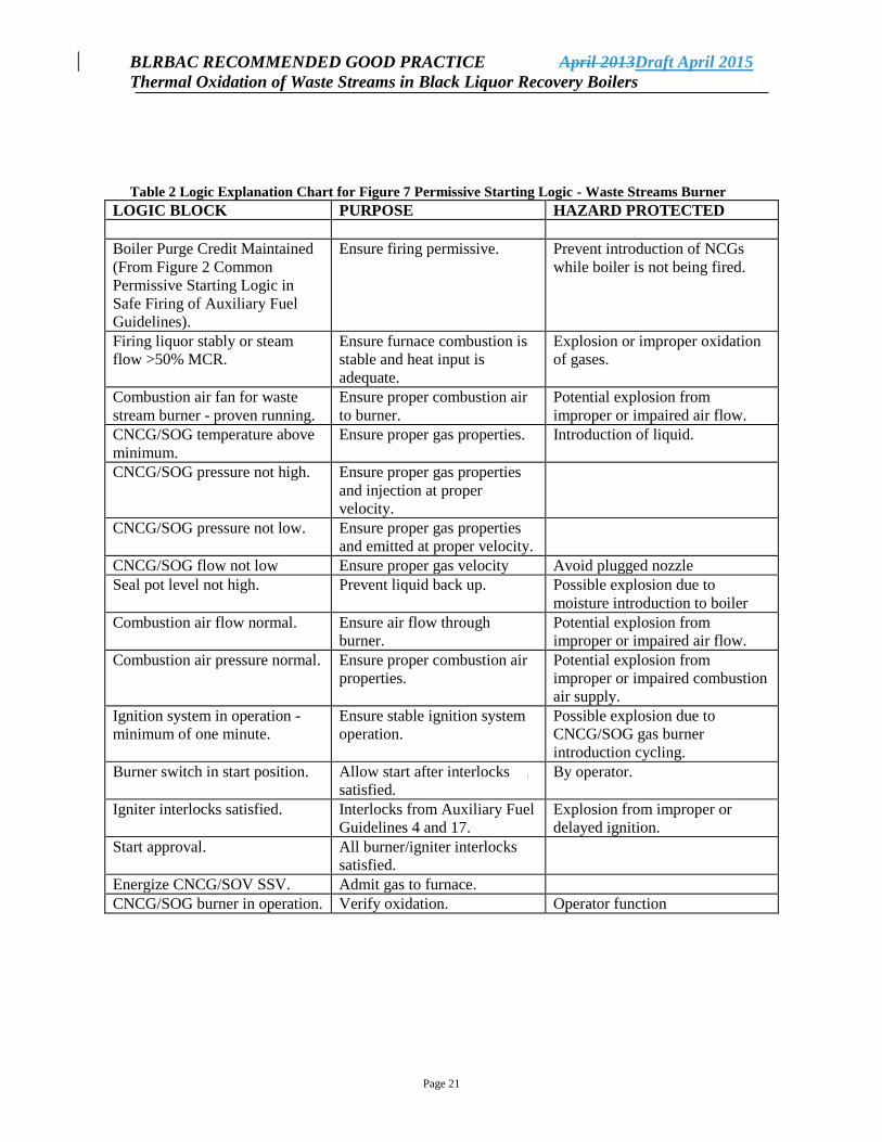
Table 2 Logic Explanation Chart for Figure 7 Permissive Starting Logic - Waste Streams Burner
LOGIC BLOCK PURPOSE HAZARD PROTECTED
Boiler Purge Credit Maintained
(From Figure 2 Common
Permissive Starting Logic in
Safe Firing of Auxiliary Fuel
Guidelines).
Ensure firing permissive. Prevent introduction of NCGs
while boiler is not being fired.
Firing liquor stably or steam
flow >50% MCR.
Ensure furnace combustion is
stable and heat input is
adequate.
Explosion or improper oxidation
of gases.
Combustion air fan for waste
stream burner - proven running.
Ensure proper combustion air
to burner.
Potential explosion from
improper or impaired air flow.
CNCG/SOG temperature above
minimum.
Ensure proper gas properties. Introduction of liquid.
CNCG/SOG pressure not high. Ensure proper gas properties
and injection at proper
velocity.
CNCG/SOG pressure not low. Ensure proper gas properties
and emitted at proper velocity.
CNCG/SOG flow not low Ensure proper gas velocity Avoid plugged nozzle
Seal pot level not high. Prevent liquid back up. Possible explosion due to
moisture introduction to boiler
Combustion air flow normal. Ensure air flow through
burner.
Potential explosion from
improper or impaired air flow.
Combustion air pressure normal. Ensure proper combustion air
properties.
Potential explosion from
improper or impaired combustion
air supply.
Ignition system in operation -
minimum of one minute.
Ensure stable ignition system
operation.
Possible explosion due to
CNCG/SOG gas burner
introduction cycling.
Burner switch in start position. Allow start after interlocks
satisfied.
By operator.
Igniter interlocks satisfied. Interlocks from Auxiliary Fuel
Guidelines 4 and 17.
Explosion from improper or
delayed ignition.
Start approval. All burner/igniter interlocks
satisfied.
Energize CNCG/SOV SSV. Admit gas to furnace.
CNCG/SOG burner in operation. Verify oxidation. Operator function
BLRBAC RECOMMENDED GOOD PRACTICE April 2013Draft April 2015
Thermal Oxidation of Waste Streams in Black Liquor Recovery Boilers
Page 22
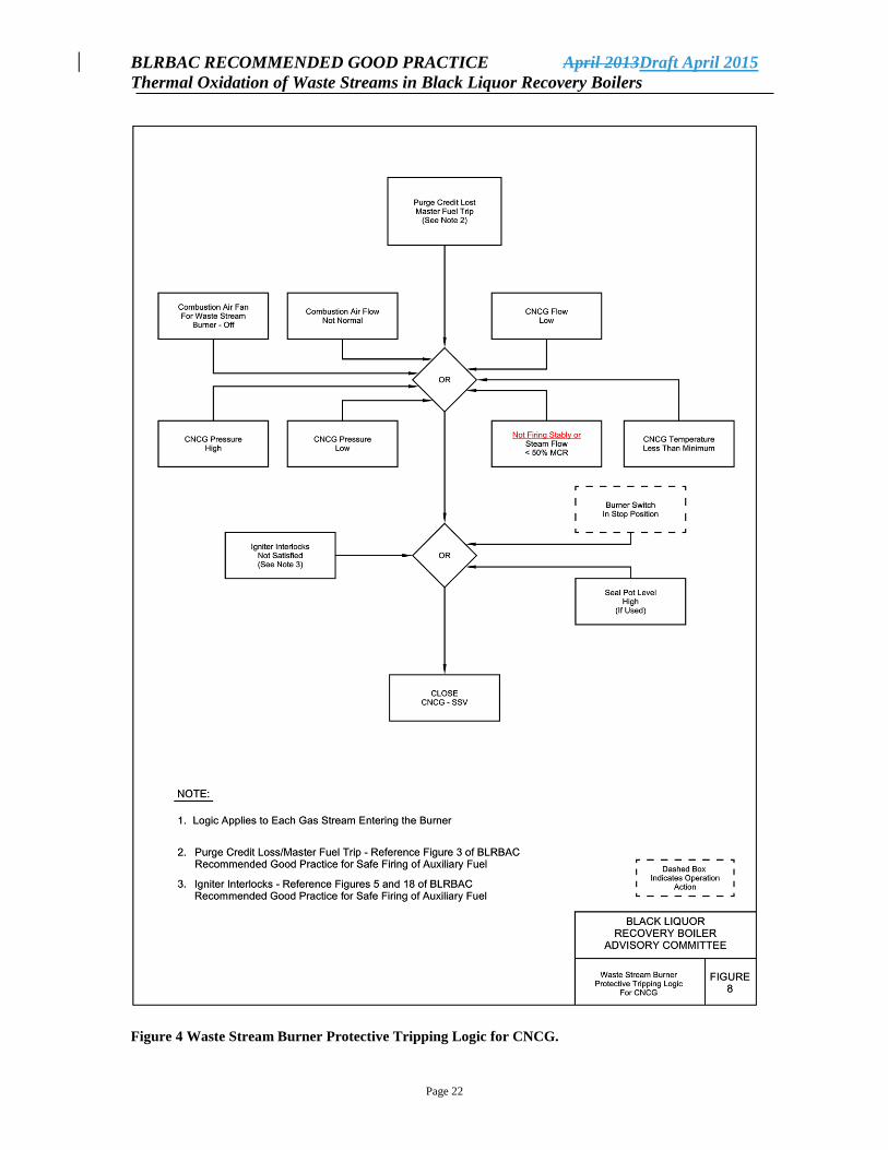
Figure 4 Waste Stream Burner Protective Tripping Logic for CNCG.
BLRBAC RECOMMENDED GOOD PRACTICE April 2013Draft April 2015
Thermal Oxidation of Waste Streams in Black Liquor Recovery Boilers
Page 23
Table 3 Logic Explanation Chart for Figure 8 Protective Tripping Logic - Waste Stream Burner
LOGIC BLOCK PURPOSE HAZARD PROTECTED
Boiler Purge Credit Lost
Master Fuel Trip
(From Figure 2 Common
Permissive Starting Logic
in Safe Firing of Aux Fuel
Guidelines).
Stop CNCG introduction
when boiler firing
permissives not met.
Prevent introduction of CNCG
while boiler is not being fired.
Not firing stably or steam
flow <50% MCR.
Stop CNCG firing when
furnace heat input is low.
Explosion or improper oxidation
of gases.
Combustion air flow not
normal.
Stop CNCG firing in the
event of air flow upsets to
burner.
Potential explosion from
improper or impaired air flow.
Combustion air fan for
waste stream burner not
running.
Stop CNCG firing when
no combustion air to
burner.
Potential explosion from
improper or impaired air flow.
CNCG/SOG pressure low
or high.
Ensure proper gas
properties and injection at
proper velocity.
Flash back up piping or poor
ignition beyond igniter.
CNCG/SOG flow low Ensure proper velocity Plugged nozzle
CNCG/SOG temperature
low.
Ensure proper gas
properties.
Introduction of liquid.
Combustion air pressure
not normal.
Ensure proper combustion
air properties.
Potential explosion from
improper or impaired
combustion air supply.
Igniter Interlocks not
satisfied.
Interlocks from Auxiliary
Fuel Guidelines 4 and 17
not met.
Explosion from improper or
delayed ignition.
Seal pot level high. Prevent liquid back up. Possible explosion due to
moisture introduction to boiler.
Burner switch in stop
mode.
Prevent firing of burner. Operator action.
Close CNCG/SOG SSV. Shutdown CNCG/SOG
burner.
BLRBAC RECOMMENDED GOOD PRACTICE April 2013Draft April 2015
Thermal Oxidation of Waste Streams in Black Liquor Recovery Boilers
Page 24
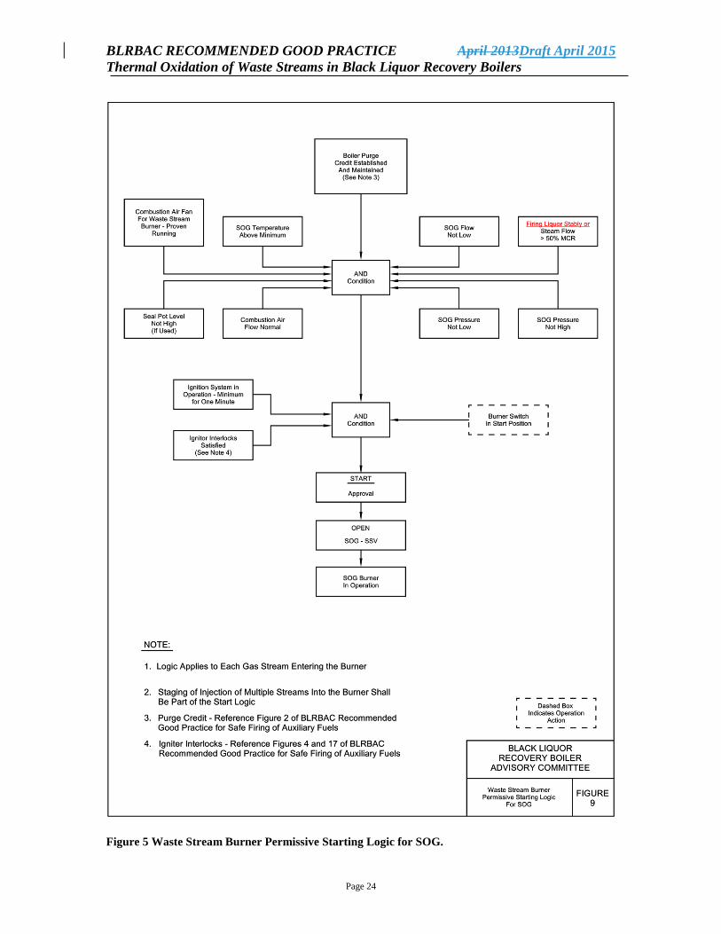
Figure 5 Waste Stream Burner Permissive Starting Logic for SOG.
BLRBAC RECOMMENDED GOOD PRACTICE April 2013Draft April 2015
Thermal Oxidation of Waste Streams in Black Liquor Recovery Boilers
Page 25
Table 4 Logic Explanation Chart for Figure 9 Permissive Starting Logic for SOG - Waste Streams
Burner
LOGIC BLOCK PURPOSE HAZARD PROTECTED
Boiler Purge Credit
Maintained
(From Figure 2 Common
Permissive Starting Logic in
Safe Firing of Auxiliary Fuel
Guidelines).
Ensure firing permissive. Prevent introduction of SOG while
boiler is not being fired.
Firing liquor stably or steam
flow >50% MCR.
Ensure furnace combustion
is stable and heat input is
adequate.
Explosion or improper oxidation of
gases.
Combustion air fan for waste
stream burner - proven
running.
Ensure proper combustion
air to burner.
Potential explosion from improper
or impaired air flow.
SOG temperature above
minimum.
Ensure proper gas properties. Introduction of liquid.
SOG pressure not high. Ensure proper gas properties
and injection at proper
velocity.
SOG pressure not low. Ensure proper gas properties
and emitted at proper
velocity.
Seal pot level not high. Prevent liquid back up. Possible explosion due to moisture
introduction to boiler
SOG flow not low. Ensure SOG line velocity is
adequate
Prevent flame propagation back
through SOG line
Combustion air flow normal. Ensure air flow through
burner.
Potential explosion from improper
or impaired air flow.
Ignition system in operation -
minimum of one minute.
Ensure stable ignition system
operation.
Possible explosion due to SOG gas
burner introduction cycling.
Burner switch in start
position.
Allow operator to start
burner after all other
interlocks satisfied.
By operator.
Igniter interlocks satisfied. Interlocks from Auxiliary
Fuel Guidelines 4 and 17.
Explosion from improper or
delayed ignition.
Start approval. All burner/igniter interlocks
satisfied.
Energize SOV SSV. Admit gas to furnace.
SOG burner in operation. Verify oxidation. Operator function.
BLRBAC RECOMMENDED GOOD PRACTICE April 2013Draft April 2015
Thermal Oxidation of Waste Streams in Black Liquor Recovery Boilers
Page 26
Figure 6 Waste Stream Burner Protective Tripping Logic for SOG.
BLRBAC RECOMMENDED GOOD PRACTICE April 2013Draft April 2015
Thermal Oxidation of Waste Streams in Black Liquor Recovery Boilers
Page 27
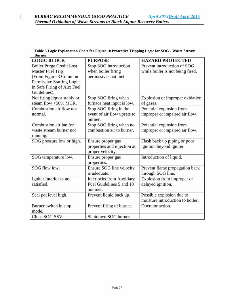
Table 5 Logic Explanation Chart for Figure 10 Protective Tripping Logic for SOG - Waste Stream
Burner
LOGIC BLOCK PURPOSE HAZARD PROTECTED
Boiler Purge Credit Lost
Master Fuel Trip
(From Figure 3 Common
Permissive Starting Logic
in Safe Firing of Aux Fuel
Guidelines).
Stop SOG introduction
when boiler firing
permissives not met.
Prevent introduction of SOG
while boiler is not being fired.
Not firing liquor stably or
steam flow <50% MCR.
Stop SOG firing when
furnace heat input is low.
Explosion or improper oxidation
of gases.
Combustion air flow not
normal.
Stop SOG firing in the
event of air flow upsets to
burner.
Potential explosion from
improper or impaired air flow.
Combustion air fan for
waste stream burner not
running.
Stop SOG firing when no
combustion air to burner.
Potential explosion from
improper or impaired air flow.
SOG pressure low or high. Ensure proper gas
properties and injection at
proper velocity.
Flash back up piping or poor
ignition beyond igniter.
SOG temperature low. Ensure proper gas
properties.
Introduction of liquid.
SOG flow low. Ensure SOG line velocity
is adequate.
Prevent flame propagation back
through SOG line.
Igniter Interlocks not
satisfied.
Interlocks from Auxiliary
Fuel Guidelines 5 and 18
not met.
Explosion from improper or
delayed ignition.
Seal pot level high. Prevent liquid back up. Possible explosion due to
moisture introduction to boiler.
Burner switch in stop
mode.
Prevent firing of burner. Operator action.
Close SOG SSV. Shutdown SOG burner.