Embed Size (px)
Citation preview
Recommendation ITU-R M.2010(03/2012)
Characteristics of a digital system, named Navigational Data for broadcasting
maritime safety and securityrelated information from shore-to-ship
in the 500 kHz band
M SeriesMobile, radiodetermination, amateur
and related satellite services
ii Rec. ITU-R M.2010
Foreword
The role of the Radiocommunication Sector is to ensure the rational, equitable, efficient and economical use of the radio-frequency spectrum by all radiocommunication services, including satellite services, and carry out studies without limit of frequency range on the basis of which Recommendations are adopted.
The regulatory and policy functions of the Radiocommunication Sector are performed by World and Regional Radiocommunication Conferences and Radiocommunication Assemblies supported by Study Groups.
Policy on Intellectual Property Right (IPR)
ITU-R policy on IPR is described in the Common Patent Policy for ITU-T/ITU-R/ISO/IEC referenced in Annex 1 of Resolution ITU-R 1. Forms to be used for the submission of patent statements and licensing declarations by patent holders are available from http://www.itu.int/ITU-R/go/patents/en where the Guidelines for Implementation of the Common Patent Policy for ITU-T/ITU-R/ISO/IEC and the ITU-R patent information database can also be found.
Series of ITU-R Recommendations
(Also available online at http://www.itu.int/publ/R-REC/en)
Series Title
BO Satellite delivery
BR Recording for production, archival and play-out; film for television
BS Broadcasting service (sound)
BT Broadcasting service (television)
F Fixed service
M Mobile, radiodetermination, amateur and related satellite services
P Radiowave propagation
RA Radio astronomy
RS Remote sensing systems
S Fixed-satellite service
SA Space applications and meteorology
SF Frequency sharing and coordination between fixed-satellite and fixed service systems
SM Spectrum management
SNG Satellite news gathering
TF Time signals and frequency standards emissions
V Vocabulary and related subjects
Note: This ITU-R Recommendation was approved in English under the procedure detailed in Resolution ITU-R 1.
Electronic Publication Geneva, 2012
ITU 2012
All rights reserved. No part of this publication may be reproduced, by any means whatsoever, without written permission of ITU.
Rec. ITU-R M.2010 1
RECOMMENDATION ITU-R M.2010
Characteristics of a digital system, named Navigational Data for broadcasting maritime safety and security
related information from shore-to-ship in the 500 kHz band
(2012)
Scope
The Recommendation describes an MF radio system, named Navigational Data (NAVDAT), for use in the maritime mobile service, operating in the 500 kHz band for digital broadcasting of maritime safety and security related information from shore-to-ship. The operational characteristics and system architecture of this radio system are included in Annexes 1 and 2. The two different modes of broadcasting data are detailed in Annexes 3 and 4
The ITU Radiocommunication Assembly,
considering
a) that high speed data broadcast from shore-to-ships enhances operational efficiency and maritime safety;
b) that the existing MF Maritime Safety Information system (NAVTEX) has limited capacity;
c) that the e-Navigation system of the International Maritime Organization (IMO) increases the demand for data transmission from shore-to-ship;
d) that the 500 kHz band provides good coverage for digital systems,
recognizing
that the Digital Radio Mondiale (DRM) system referenced in Annex 4 has been incorporated in Recommendation ITU-R BS.1514-2,
noting
that Report ITU-R M.2201 provides the basis for NAVDAT system,
recommends
1 that the operational characteristics for the broadcasting of maritime safety and security related information should be in accordance with Annex 1;
2 that the system architecture of the broadcasting system for maritime safety and security related information should be in accordance with Annex 2;
3 that the technical characteristics and modem protocols for digital data transmission from shore-to-ships in the 500 kHz band should be in accordance with Annex 3 or Annex 4.
2 Rec. ITU-R M.2010
Annex 1
Operational characteristics
The NAVDAT system uses a time-slot allocation similar to the NAVTEX system which could be coordinated by IMO in the same manner.
That NAVDAT system can also work on Single Frequency Network (SFN) as described in Annex 4. In this case transmitters are frequency synchronized and the transmit data must be the same for all transmitter.
The NAVDAT 500 kHz digital system offers a broadcast transmission of any kind of message from shore-to-ships with possibility of encryption.
1 Type of messages
Any broadcasting message should be provided by a secure and controlled source.
Message types broadcast can include, but are not limited to, the following:
– safety of navigation;
– security;
– piracy;
– search and rescue;
– meteorological messages;
– piloting or harbour messages;
– vessel traffic system files transfer.
2 Broadcast modes
2.1 General broadcast
These messages are broadcasted for the attention of all ships.
2.2 Selective broadcast
These messages are broadcasted for the attention of a group of ships or in a specific navigation area.
2.3 Dedicated message
These messages are addressed to one ship, using the maritime mobile service identity.
Rec. ITU-R M.2010 3
Annex 2
System architecture
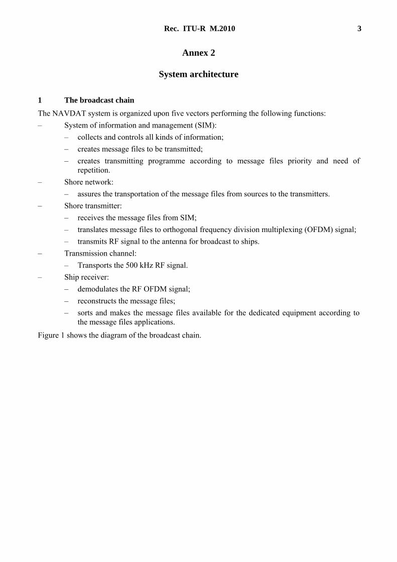
1 The broadcast chain
The NAVDAT system is organized upon five vectors performing the following functions:
– System of information and management (SIM):
– collects and controls all kinds of information;
– creates message files to be transmitted;
– creates transmitting programme according to message files priority and need of repetition.
– Shore network:
– assures the transportation of the message files from sources to the transmitters.
– Shore transmitter:
– receives the message files from SIM;
– translates message files to orthogonal frequency division multiplexing (OFDM) signal;
– transmits RF signal to the antenna for broadcast to ships.
– Transmission channel:
– Transports the 500 kHz RF signal.
– Ship receiver:
– demodulates the RF OFDM signal;
– reconstructs the message files;
– sorts and makes the message files available for the dedicated equipment according to the message files applications.
Figure 1 shows the diagram of the broadcast chain.
4 Rec. ITU-R M.2010
FIGURE 1
NAVDAT 500 kHz broadcast chain block diagram
M.2010-01
Shoretransmitter
Shipreceiver
Transmission channel 500 kHz
Shorenetwork
System of information and management(SIM)
Controls/signalisations
Message files
MessagesTypes No. 1
MessagesTypes No. n
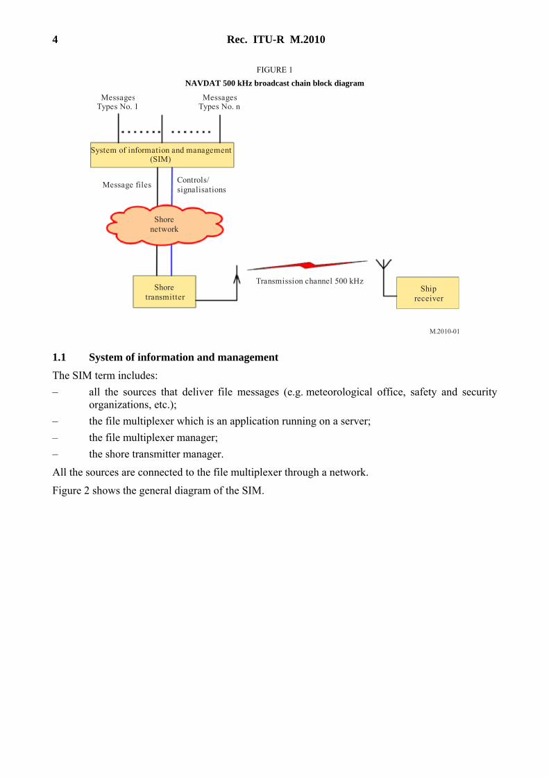
1.1 System of information and management
The SIM term includes:
– all the sources that deliver file messages (e.g. meteorological office, safety and security organizations, etc.);
– the file multiplexer which is an application running on a server;
– the file multiplexer manager;
– the shore transmitter manager.
All the sources are connected to the file multiplexer through a network.
Figure 2 shows the general diagram of the SIM.
Rec. ITU-R M.2010 5
FIGURE 2
NAVDAT system of information and management block diagram
M.2010-02
Shorenetwork
File multiplexerFile multiplexer
manager
Shore transmittermanager
Message filesControls/signalisations
MessagesTypes No.1
MessagesTypes No.n
1.1.1 File multiplexer
The file multiplexer:
– takes delivery of the message files from the data sources;
– encrypts the message files if asked;
– formats the file messages with recipient information, priority status and time validity;
– sends the message files to the transmitter.
1.1.2 File multiplexer manager
The file multiplexer manager is a man machine interface that enables the user to, among other tasks:
– have a look at the message files coming from any source;
– specify the priority and periodicity of the any message file;
– specify the recipient of any message file;
– manage the file message encryption.
Some of these functionalities may be automated. As an example, the priority and the periodicity of a message may be selected according to the source it comes from or the source may specify the priority in the message.
1.1.3 Shore transmitter manager
The shore station manager is a man machine interface connected to the transmitter through the network; it makes it possible to supervise the transmitter status indications such as:
– transmit acknowledgment;
– alarms;
– effective transmit power;
– synchronization report;
and to change the transmitter parameters, such as:
– transmit power;
6 Rec. ITU-R M.2010
– OFDM parameters (pilot subcarriers, error coding, etc.);
– transmission schedule.
1.2 Shore network
The shore network can use a broadband link, a low data rate link or a local file sharing.
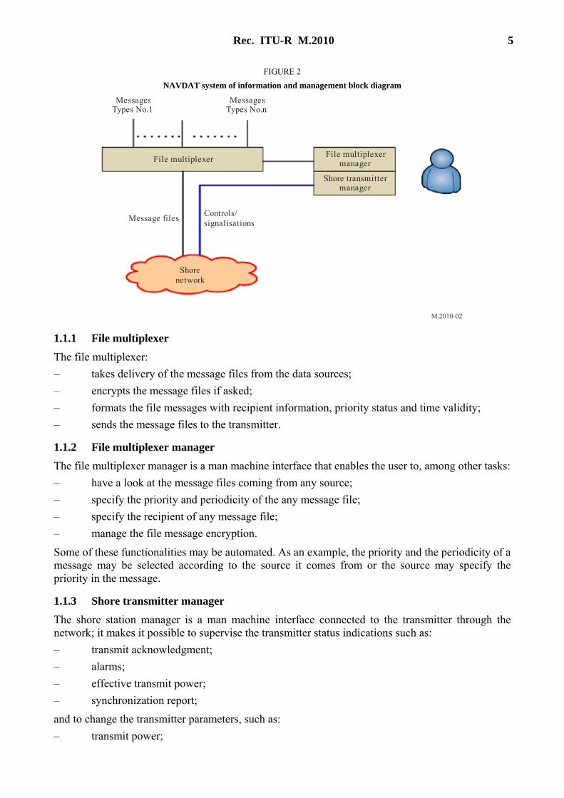
1.3 Shore transmitter description
A coastal transmitting station consists of this minimum configuration:
– one local server connected to a protected access;
– one OFDM modulator;
– one 500 kHz amplifier;
– one transmit antenna with matching unit;
– one GNSS receiver or atomic clock for synchronization;
– one monitoring receiver with its antenna.
1.3.1 Shore system architecture
Figure 3 shows the block diagram of a 500 kHz digital transmitter.
FIGURE 3
NAVDAT 500 kHz transmitter functional block diagram
M.2010-03
Shorenetwork
Controller
Matchingunit
Message filesControls/signalisations
500 kHzmonitoring
receiver
RFamplifier
RFgenerator
Modulator
DS
TIS
MIS
Controls/signalisations
Controls/signalisations
Controls/signalisations
GNSS receiveror
reference clock
Txantenna
1.3.2 Controller
This unit receives some pieces of information:
– message files from SIM;
Rec. ITU-R M.2010 7
– GNSS or reference clock for synchronization;
– 500 kHz signal from monitoring receiver;
– 500 kHz modulator and transmitter control signals.
The function of the controller is:
– to check if the frequency band is free before transmission;
– to synchronize all signals on the coast station from synchronization clock;
– to control the transmission parameters, time and schedule;
– to format the message files to be transmitted (split files into packets).
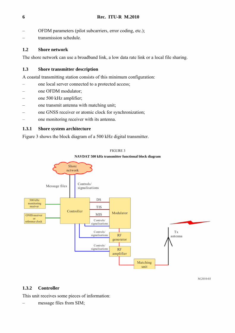
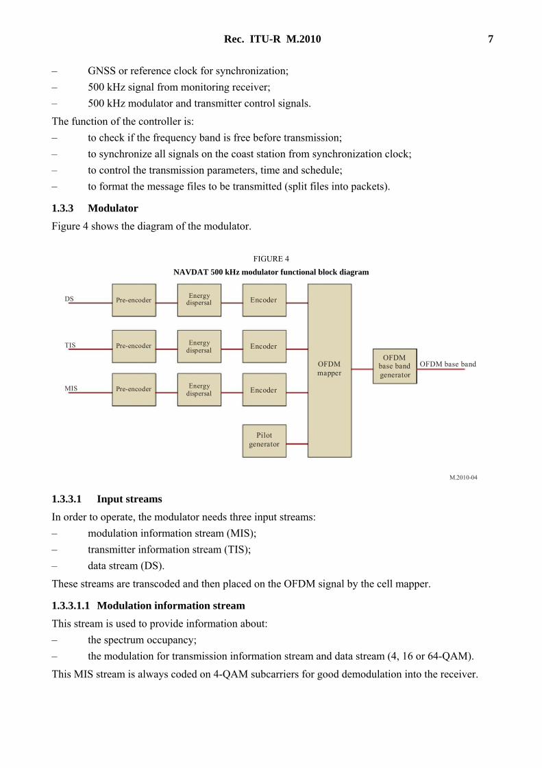
1.3.3 Modulator
Figure 4 shows the diagram of the modulator.
FIGURE 4
NAVDAT 500 kHz modulator functional block diagram
M.2010-04
Pilotgenerator
OFDMbase bandgenerator
EncoderEnergy
dispersal
OFDMmapper
OFDM base band
Encoder
Encoder
Energydispersal
EnergydispersalPre-encoder
Pre-encoder
Pre-encoder
DS
TIS
MIS
1.3.3.1 Input streams
In order to operate, the modulator needs three input streams:
– modulation information stream (MIS);
– transmitter information stream (TIS);
– data stream (DS).
These streams are transcoded and then placed on the OFDM signal by the cell mapper.
1.3.3.1.1 Modulation information stream
This stream is used to provide information about: – the spectrum occupancy;
– the modulation for transmission information stream and data stream (4, 16 or 64-QAM).
This MIS stream is always coded on 4-QAM subcarriers for good demodulation into the receiver.
8 Rec. ITU-R M.2010
1.3.3.1.2 Transmitter information stream
This stream is used to provide information to the receiver about:
– error coding for data stream (should be different for surface wave propagation at day time and for surface + sky wave propagation at night time);
– identifier of the transmitter;
– date and time.
This TIS stream can be coded on 4 or 16-QAM.
1.3.3.1.3 Data stream
It contains the message files to transmit (these message files were previously formatted by the file multiplexer).
1.3.3.2 Error encoding
The error correction scheme determines the robustness of the coding, The code rate is the ratio between useful and raw data rate. It illustrates the transmission efficiency and can vary from 0.5 to 0.75 depending on the error correction schemes and modulation patterns.
1.3.3.3 OFDM generation
The three streams (MIS, TIS and DS) are formatted:
– encoding;
– energy dispersal.
A cell mapper organizes the OFDM cells with the formatted streams and the pilot cells. The pilot cells are transmitted for the receiver to estimate the radio channel and synchronize on the RF signal.
An OFDM signal generator creates the OFDM base band according to the output of the cell mapper.
1.3.4 500 kHz RF generator
A 500 kHz RF generator transposes the base band signal to 500 kHz RF output carrier.
An amplifier brings the RF signal to the desired power.
1.3.5 RF amplifier
The function of this stage is to amplify the 500 kHz signal from the generator output to the necessary level to obtain the desired radio coverage.
The OFDM transmission introduces a crest factor on the RF signal. This crest factor must stay in the range 7 to 10 dB at the RF amplifier output for a correct modulation error rate (MER).
1.3.6 Transmit antenna with matching unit
The RF amplifier is connected to the transmit antenna through the impedance matching unit.
1.3.7 Global navigation satellite receiver and a backup atomic reference clock
The clock is used to synchronize the local controller.
1.3.8 Monitoring receiver
The monitoring receiver checks that the frequency is free before transmission and offers possibility to check the transmission.
Rec. ITU-R M.2010 9
1.4 Transmission channel: Radio coverage estimation
The coverage could be calculated based on Recommendations ITU-R P.368-9 and ITU-R P.372-10. See Report ITU-R M.2201 for an example.
Annex 3
NAVDAT technical characteristics
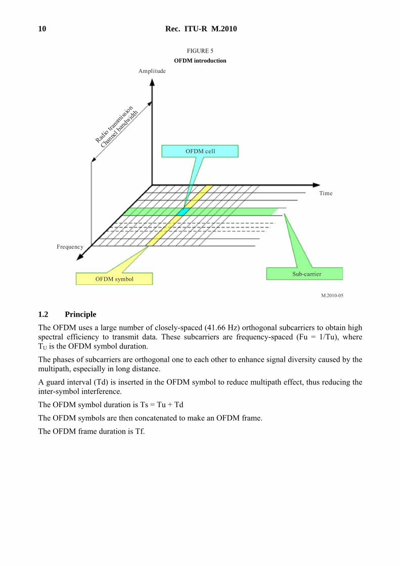
1 Modulation principle
The system uses OFDM which is a modulation technology for digital transmissions.
1.1 Introduction The bandwidth of the radio transmission channel is divided in the frequency domain to form subcarriers.
The radio transmission channel occupancy is organized in the time to form OFDM symbols.
An OFDM cell is equivalent to one subcarrier in one OFDM symbol.
10 Rec. ITU-R M.2010
FIGURE 5
OFDM introduction
M.2010-05
Radio tra
nsmiss
ion
Channe
l ban
dwidth
OFDM symbol
Time
Frequency
Sub-carrier
OFDM cell
Amplitude
1.2 Principle The OFDM uses a large number of closely-spaced (41.66 Hz) orthogonal subcarriers to obtain high spectral efficiency to transmit data. These subcarriers are frequency-spaced (Fu = 1/Tu), where TU is the OFDM symbol duration.
The phases of subcarriers are orthogonal one to each other to enhance signal diversity caused by the multipath, especially in long distance.
A guard interval (Td) is inserted in the OFDM symbol to reduce multipath effect, thus reducing the inter-symbol interference.
The OFDM symbol duration is Ts = Tu + Td
The OFDM symbols are then concatenated to make an OFDM frame.
The OFDM frame duration is Tf.
Rec. ITU-R M.2010 11
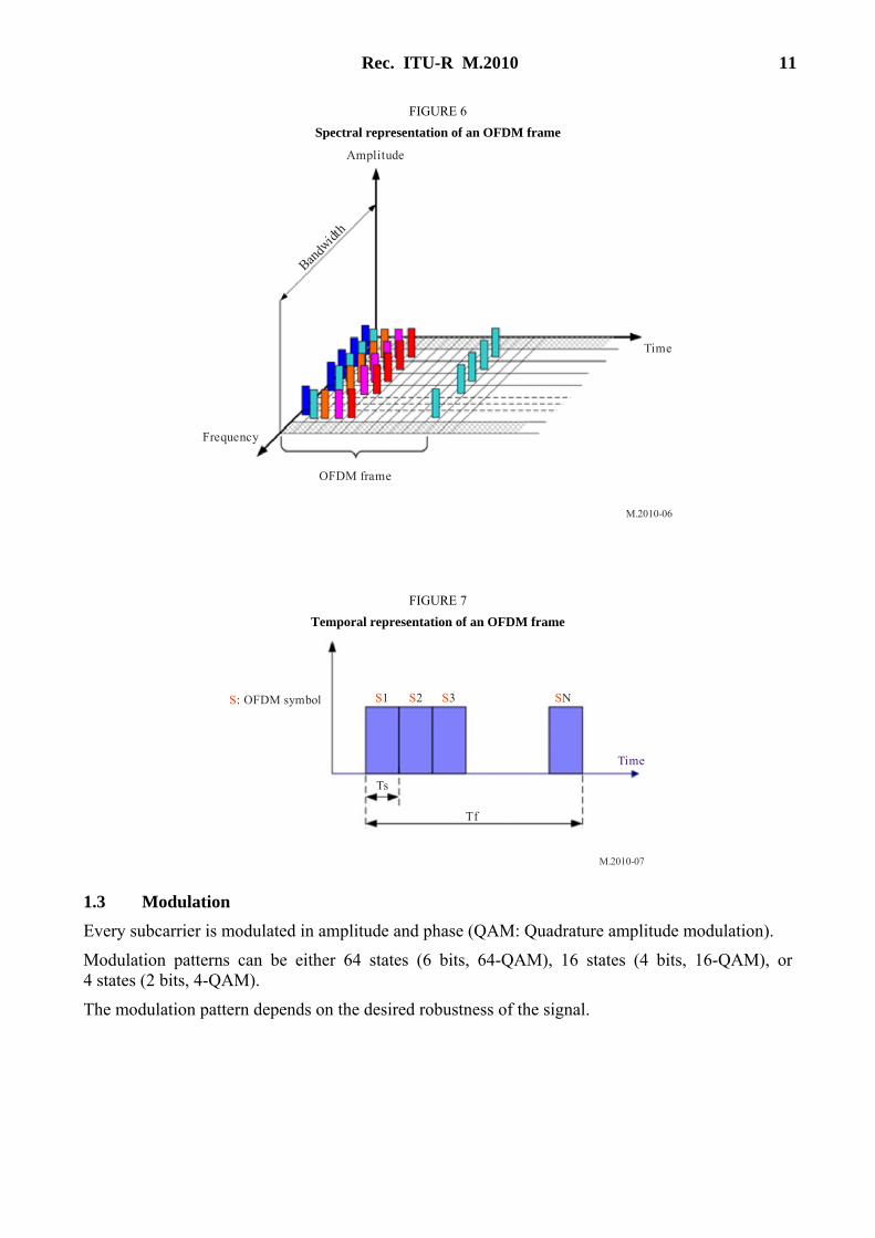
FIGURE 6
Spectral representation of an OFDM frame
M.2010-06
Bandw
idth
OFDM frame
Time
Frequency
Amplitude
FIGURE 7
Temporal representation of an OFDM frame
M.2010-07
S: OFDM symbol
Time
Tf
S1 S2 S3 SN
Ts
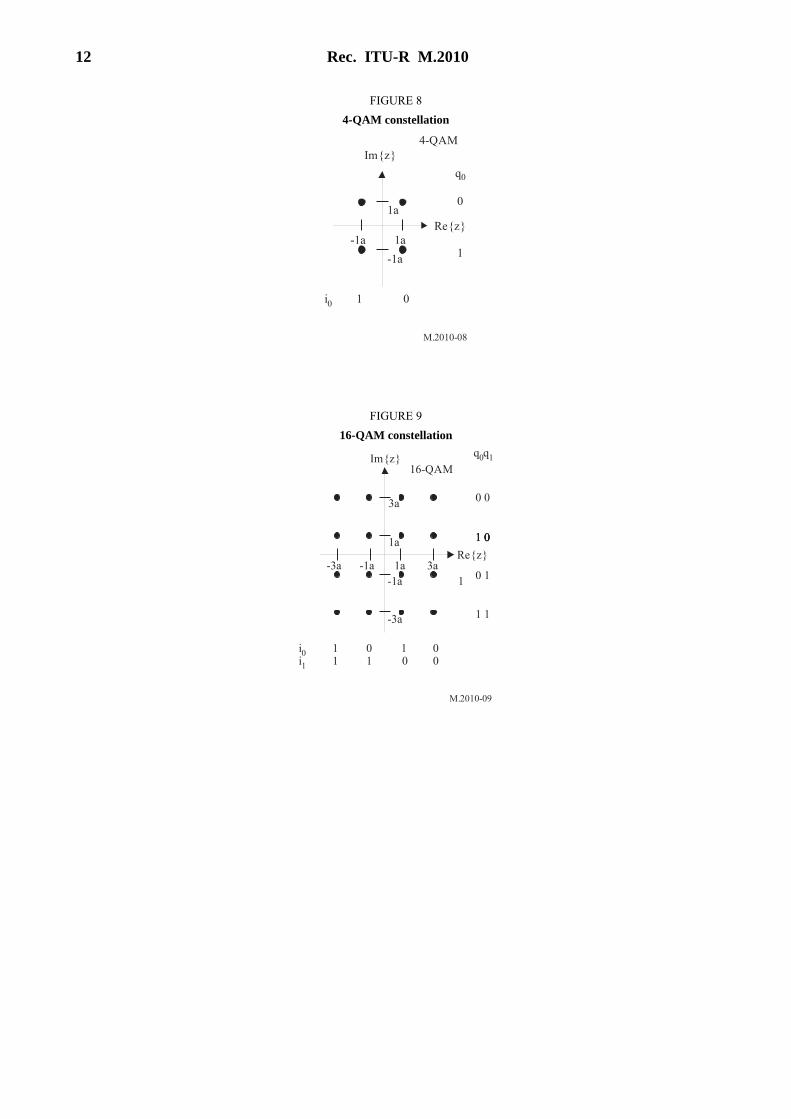
1.3 Modulation
Every subcarrier is modulated in amplitude and phase (QAM: Quadrature amplitude modulation).
Modulation patterns can be either 64 states (6 bits, 64-QAM), 16 states (4 bits, 16-QAM), or 4 states (2 bits, 4-QAM).
The modulation pattern depends on the desired robustness of the signal.
12 Rec. ITU-R M.2010
FIGURE 8
4-QAM constellation
M.2010-08
4-QAM
0
Re{z}1a
1a
-1a
-1a1
01i0
q0
Im{z}
FIGURE 9
16-QAM constellation
M.2010-09
16-QAM
1 0
Re{z}1a
1a-1a
-1a1
01i0
q0q1Im{z}
3a
-3a 3a
1 01 01 0
0 0
0 1
1 1-3a
i1 1 110
00
Rec. ITU-R M.2010 13
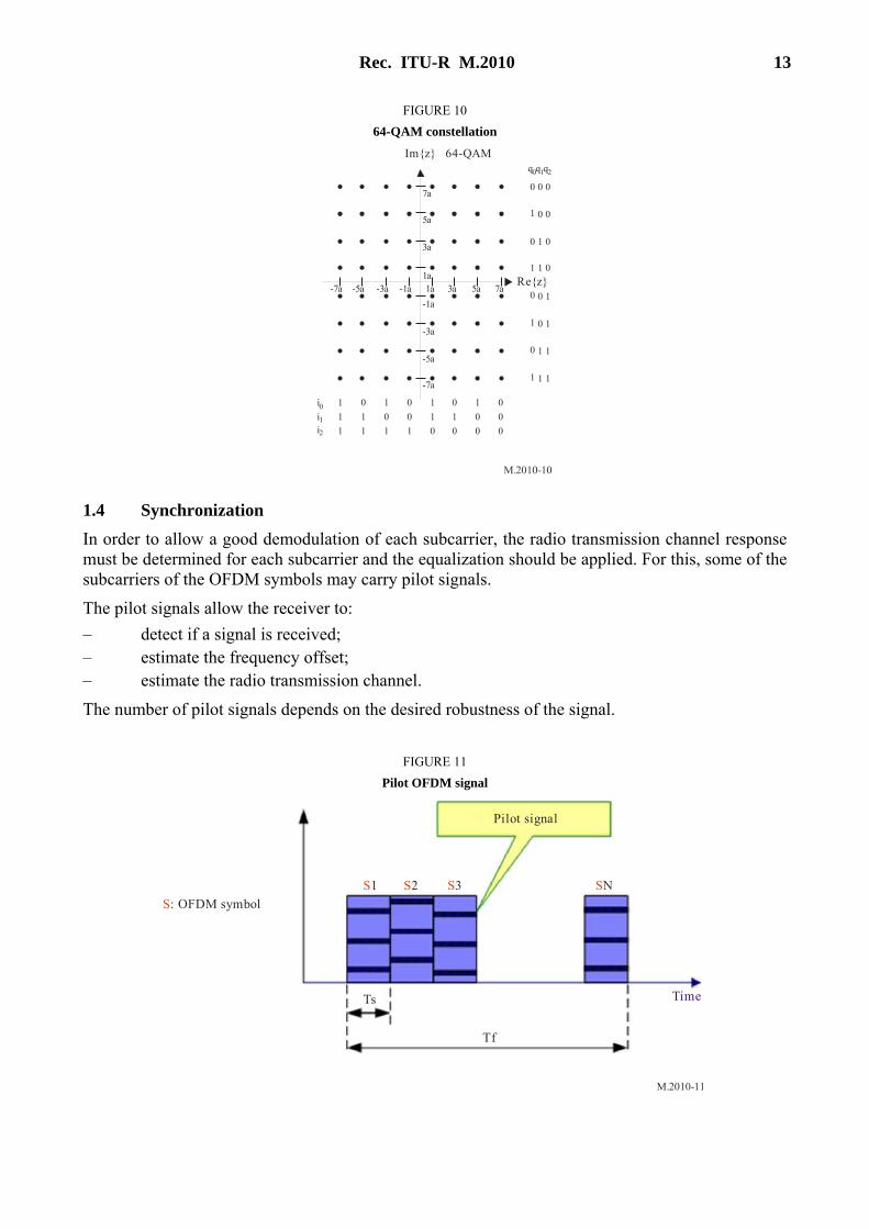
FIGURE 10
64-QAM constellation
M.2010-10
64-QAM
Re{z}1a
-1a
-1a
i0
q0q q1 2
Im{z}
-3a
0
i1
0
3a
5a
7a
-3a
-5a
-7a
1a 3a 5a 7a-5a-7a
0
0
1
0
0
0
1
0
1
1
0
0
0
1
1
0
1
0
1
1
1
1
1i2
0 0
1 0 0
0 1 0
1 1 0
0 0 1
1 0 1
0 1 1
1 1 1
1.4 Synchronization
In order to allow a good demodulation of each subcarrier, the radio transmission channel response must be determined for each subcarrier and the equalization should be applied. For this, some of the subcarriers of the OFDM symbols may carry pilot signals.
The pilot signals allow the receiver to:
– detect if a signal is received; – estimate the frequency offset; – estimate the radio transmission channel.
The number of pilot signals depends on the desired robustness of the signal.
FIGURE 11
Pilot OFDM signal
M.2010-11
Pilot signal
S: OFDM symbol
S1 S2 S3 SN
Ts
Tf
Time
14 Rec. ITU-R M.2010
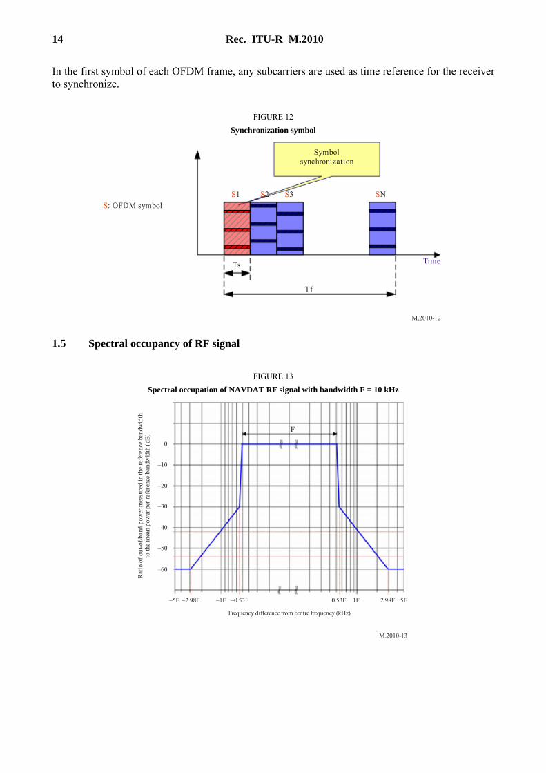
In the first symbol of each OFDM frame, any subcarriers are used as time reference for the receiver to synchronize.
FIGURE 12
Synchronization symbol
M.2010-12
Symbolsynchronization
S: OFDM symbol
S1 S2 S3 SN
Ts
Tf
Time
1.5 Spectral occupancy of RF signal
FIGURE 13
Spectral occupation of NAVDAT RF signal with bandwidth F = 10 kHz
M.2010-13
F
–5F –2.98F –1F –0.53F 2.98F0.53F 5F
Rat
io o
f ou
t-of
-ban
d po
wer
mea
sure
d in
the
refe
renc
e ba
ndw
idth
to th
e m
ean
pow
er p
er re
fere
nce
band
wid
th (
dB)
–60
–50
–40
–30
–20
–10
0
Frequency difference from centre frequency (kHz)
1F
Rec. ITU-R M.2010 15
2 Estimated usable data rate
In the 10 kHz channel bandwidth with 500 kHz propagation, the raw data rate available for the data stream (DS) is typically around 25 kbit/s with 16-QAM signal.
The number of subcarriers that hold data can be varied in order to adjust the channel protection. Higher channel protection (protection against multipath, fading, delay, etc.) results in a lower number of useful subcarriers.
Error coding must then be applied to the raw data rate to obtain the useful data rate. With a code rate of 0.5 to 0.75, the useful data rate is then between 12 and 18 kbit/s.
A higher code rate provides a higher useful data rate but the radio coverage is accordingly reduced.
3 NAVDAT ship receiver
3.1 NAVDAT ship receiver description
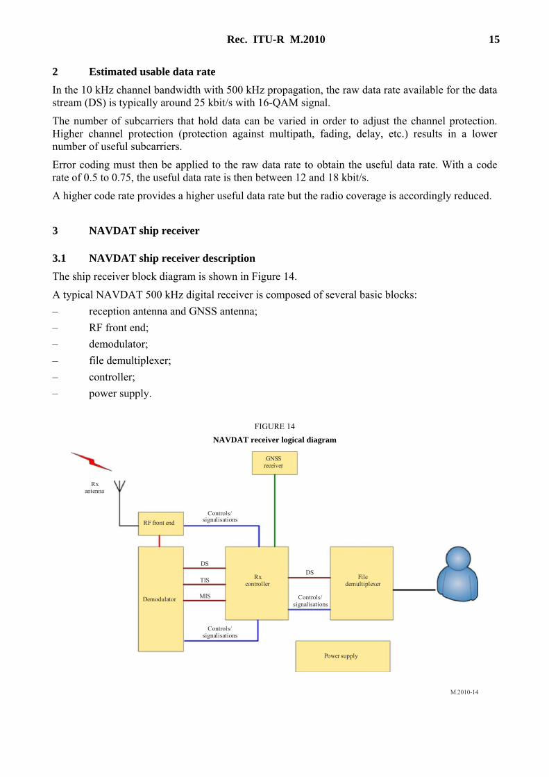
The ship receiver block diagram is shown in Figure 14.
A typical NAVDAT 500 kHz digital receiver is composed of several basic blocks:
– reception antenna and GNSS antenna;
– RF front end;
– demodulator;
– file demultiplexer;
– controller;
– power supply.
FIGURE 14
NAVDAT receiver logical diagram
M.2010-14
GNSSreceiver
Power supply
Controls/signalisations
Rxcontroller
Rxantenna
RF front end
Demodulator
DS
TIS
MIS Controls/signalisations
DSFile
demultiplexer
Controls/signalisations
16 Rec. ITU-R M.2010
3.1.1 Reception antenna and global navigation satellite antenna
The 500 kHz receiving antenna can be an H field antenna (recommended on a noisy ship) or an E field antenna.
A GNSS antenna (or connection to the existing ship GNSS receiver) is also needed in order to obtain the ship position.
3.1.2 RF front end
This block includes the RF filter, RF amplifier and base band output.
High sensitivity and high dynamic range are necessary.
3.1.3 Demodulator
This stage demodulates the base band OFDM signal and recreates the data stream that holds the transmitted message files.
It implements:
– time/frequency synchronization;
– channel estimation;
– automatic modulation recovery;
– error correction.
The NAVDAT receiver should be able to detect the following modulation parameters automatically:
– 16 or 64-QAM;
– subcarriers scheme;
– type of error coding.
In addition to the DS, it reports the information filled in the TIS and MIS. Furthermore, it reports complementary information about the channel such as:
– estimated SNR;
– BER;
– MER.
3.1.4 File demultiplexer
The file demultiplexer:
– receives the message files from the controller;
– verifies that the message files are marked for its attention (type of broadcast mode);
– decrypts the message files if needed/able;
– makes the message files available for the terminal application that will use the message files;
– deletes the out-of-date message files.
Depending on the final application, the message file can be:
– stored on an onboard server accessible through the ship network;
– sent directly to the final application.
Rec. ITU-R M.2010 17
A man machine interface should be available in order to display the dedicated messages and to configure the interface with the application dedicated onboard devices (e.g. e-navigation) and manage the ship board permissions (ship identification, encryption). This interface may be a dedicated application running on an external computer while the receiver may be a black-box device.
3.1.5 Controller
The controller:
– extracts the message files from the DS (merge packets into files);
– interprets the TIS and MIS and the other pieces of information given by the demodulator;
– collects the following information from the file demultiplexer:
• total number of decoded message files;
• number of available message files;
• error event (e.g. decrypt errors).
A man machine interface may be available in order to display and check the reception parameters.
3.1.6 Power supply
The main power supply must be adapted to the main power supply of the ship.
4 NAVDAT ship receiver performance specifications
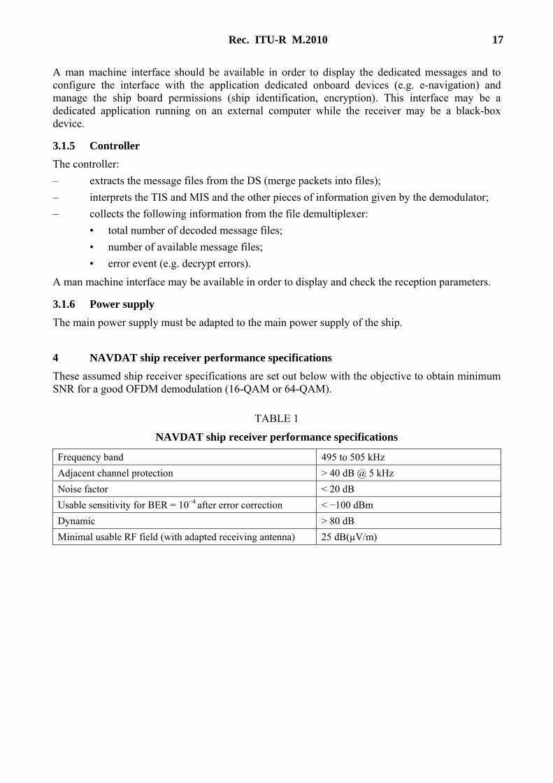
These assumed ship receiver specifications are set out below with the objective to obtain minimum SNR for a good OFDM demodulation (16-QAM or 64-QAM).
TABLE 1
NAVDAT ship receiver performance specifications
Frequency band 495 to 505 kHz
Adjacent channel protection > 40 dB @ 5 kHz
Noise factor < 20 dB
Usable sensitivity for BER = 10−4 after error correction < −100 dBm
Dynamic > 80 dB
Minimal usable RF field (with adapted receiving antenna) 25 dB(µV/m)
18 Rec. ITU-R M.2010
Annex 4
Single frequency network mode of Digital Radio Mondiale
1 Explanation of Digital Radio Mondiale
The international digital radio broadcast standard Digital Radio Mondiale (DRM) is used for digital radio broadcasting at MF and HF. DRM is a proven technology that provides superior coverage, improves signal fidelity (through digital error correction coding), eliminates multi-path interference (including sky-wave interference) and thus extends coverage from sky-wave propagated signals. DRM broadcasts are implemented in both 16-QAM and 64-QAM modulation modes, depending on coverage requirements, transmitter location, power and antenna height.
1.1 Single frequency network operating mode The DRM system is capable of supporting what is called “Single Frequency Network (SFN) operation”. This is the case where a number of transmitters transmit on the same frequency, and at the same time, identical data signals. Generally these transmitters are arranged to have overlapping coverage areas, within which a radio will receive signals from more than one transmitter. Provided that these signals arrive within a time difference of less than the guard interval, they will provide positive signal reinforcement. Thus, the service coverage will be improved at that location compared to that obtained if there was only a single transmitter providing service to that location. By careful design, and using a number of transmitters in a SFN, a region or country may be completely covered using a single frequency, and in this application, a single time slot, thus drastically improving spectrum efficiency.
Annex 5
Glossary
BER Bit error rate
DRM Digital radio mondiale
DS Data stream
GMDSS Global maritime distress and safety system
GNSS Global navigation satellite system
IMO International Maritime Organization
ITU International Telecommunication Union
LF Low frequency
MF Medium frequency
MER Modulation error rate
MIS Modulation information stream
NAVDAT Navigational Data (the system name)
NAVTEX Navigational Telex (the system name)

Rec. ITU-R M.2010 19
NM Nautical mile (1852 metres)
OFDM Orthogonal frequency division multiplexing
QAM Quadrature amplitude modulation
PEP Peak envelope power
RMS Root mean square
SFN Single frequency network
SIM System of information and management
SNR Signal-to-noise ratio
TIS Transmitter information stream