Embed Size (px)
Citation preview
Recommendation ITU-R F.635-6(05/2001)
Radio-frequency channel arrangements based on a homogeneous pattern for
fixed wireless systems operating in the 4 GHz band
F Series
Fixed service
Rec. ITU-R F.635-6 ii
Foreword
The role of the Radiocommunication Sector is to ensure the rational, equitable, efficient and economical use of the radio-frequency spectrum by all radiocommunication services, including satellite services, and carry out studies without limit of frequency range on the basis of which Recommendations are adopted.
The regulatory and policy functions of the Radiocommunication Sector are performed by World and Regional Radiocommunication Conferences and Radiocommunication Assemblies supported by Study Groups.
Policy on Intellectual Property Right (IPR)
ITU-R policy on IPR is described in the Common Patent Policy for ITU-T/ITU-R/ISO/IEC referenced in Annex 1 of Resolution ITU-R 1. Forms to be used for the submission of patent statements and licensing declarations by patent holders are available from http://www.itu.int/ITU-R/go/patents/en where the Guidelines for Implementation of the Common Patent Policy for ITU-T/ITU-R/ISO/IEC and the ITU-R patent information database can also be found.
Series of ITU-R Recommendations (Also available online at http://www.itu.int/publ/R-REC/en)
Series Title
BO Satellite delivery BR Recording for production, archival and play-out; film for television BS Broadcasting service (sound) BT Broadcasting service (television) F Fixed service M Mobile, radiodetermination, amateur and related satellite services P Radiowave propagation RA Radio astronomy RS Remote sensing systems S Fixed-satellite service SA Space applications and meteorology SF Frequency sharing and coordination between fixed-satellite and fixed service systems SM Spectrum management SNG Satellite news gathering TF Time signals and frequency standards emissions V Vocabulary and related subjects
Note: This ITU-R Recommendation was approved in English under the procedure detailed in Resolution ITU-R 1.
Electronic Publication Geneva, 2009
© ITU 2009
All rights reserved. No part of this publication may be reproduced, by any means whatsoever, without written permission of ITU.
Rec. ITU-R F.635-6 1
RECOMMENDATION ITU-R F.635-6*
Radio-frequency channel arrangements based on a homogeneous pattern for fixed wireless systems operating in the 4 GHz band
(1986-1990-1992-1995-1997-1999-2001)
Scope
This Recommendation provides specifications for radio-frequency channel arrangements based on an homogeneous pattern for fixed wireless systems in the frequency range 3 400-4 200 MHz. Annex 1 includes arrangements with 30 to 90 MHz separations using homogeneous patterns.
The ITU Radiocommunication Assembly,
considering a) that high-capacity digital fixed wireless systems of the order of 90 Mbit/s, 140 Mbit/s or synchronous digital hierarchy (SDH) bit rates are required in the 4 GHz radio-frequency (RF) bands;
b) that the lower band limits of the 4 GHz RF bands are not uniform and vary internationally from 3 400 to 3 800 MHz;
c) that efficient use of bands of different width can be achieved by RF channel arrangements matched to the width of the band available;
d) that a high degree of compatibility between RF channels of different arrangements can be achieved by selecting all channel centre frequencies from a uniform basic pattern;
e) that the centre gaps of the individual channel arrangements and the guard spacing at the edges of the band can be chosen by non-occupancy of a suitable number of RF-channel positions in a homogeneous basic pattern;
f) that the uniform basic pattern spacing should not be unjustifiably small (i.e. the number of RF-channel positions too high) nor so large as to jeopardize efficient use of the available spectrum;
g) that the absolute frequencies of the basic pattern should be defined by a single reference frequency;
h) that single- and multi-carrier digital fixed wireless systems are both useful concepts to achieve the best technical and economic trade-off in the system design,
recommends 1 that the preferred RF channel arrangement for high-capacity digital fixed wireless systems of the order of 90 Mbit/s, 140 Mbit/s or SDH bit rates (see Note 1), operating in the 4 GHz band, should be selected from a homogeneous pattern with the following characteristics.
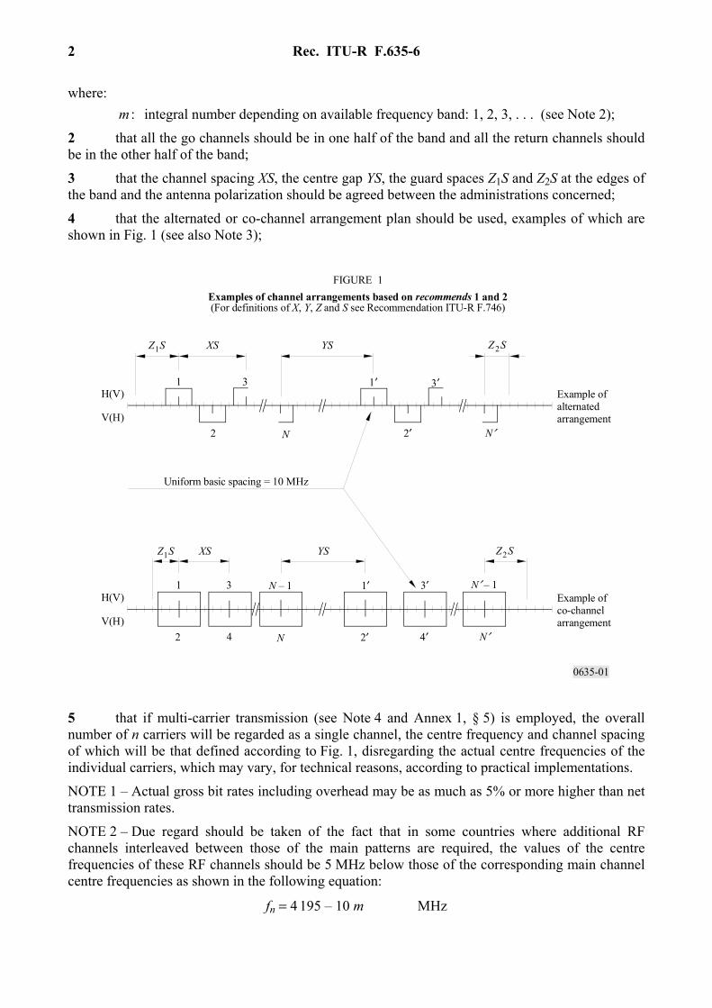
Centre frequencies fn of the RF channels within the basic pattern:
fn = 4 200 – 10 m MHz (1)
____________________ * Radiocommunication Study Group 5 made editorial amendments to this Recommendation in 2009 in
accordance with Resolution ITU-R 1.
Rec. ITU-R F.635-6 2
where: m : integral number depending on available frequency band: 1, 2, 3, . . . (see Note 2);
2 that all the go channels should be in one half of the band and all the return channels should be in the other half of the band;
3 that the channel spacing XS, the centre gap YS, the guard spaces Z1S and Z2S at the edges of the band and the antenna polarization should be agreed between the administrations concerned;
4 that the alternated or co-channel arrangement plan should be used, examples of which are shown in Fig. 1 (see also Note 3);
0635-01
42
1 3
2
1 3
3′1′
2′
1′ 3′
2′ 4′
Z2SXS YSZ1S
Z2SXS YSZ1S
FIGURE 1Examples of channel arrangements based on recommends 1 and 2(For definitions of X, Y, Z and S see Recommendation ITU-R F.746)
N N′
N′N
N′ – 1N – 1
H(V)
V(H)
H(V)
V(H)
Uniform basic spacing = 10 MHz
Example ofco-channelarrangement
Example ofalternatedarrangement
5 that if multi-carrier transmission (see Note 4 and Annex 1, § 5) is employed, the overall number of n carriers will be regarded as a single channel, the centre frequency and channel spacing of which will be that defined according to Fig. 1, disregarding the actual centre frequencies of the individual carriers, which may vary, for technical reasons, according to practical implementations.
NOTE 1 – Actual gross bit rates including overhead may be as much as 5% or more higher than net transmission rates.
NOTE 2 – Due regard should be taken of the fact that in some countries where additional RF channels interleaved between those of the main patterns are required, the values of the centre frequencies of these RF channels should be 5 MHz below those of the corresponding main channel centre frequencies as shown in the following equation:
fn = 4 195 – 10 m MHz
Rec. ITU-R F.635-6 3
NOTE 3 – Due regard should be taken of the fact that in some countries the band 3 700-4 200 MHz is used. A RF channel arrangement, using this band and based on the homogeneous pattern is given in Annex 1, § 4.
NOTE 4 – A multi-carrier system is a system with n (where n > 1) digitally modulated carrier signals simultaneously transmitted (or received) by the same RF equipment. The centre frequency should be regarded as the arithmetic average of the n individual carrier frequencies of the multi-carrier system.
ANNEX 1
Frequency arrangements derived from a homogeneous frequency pattern for the 4 GHz band
RF channel arrangements derived from recommends 1 for the 4 GHz band are described below.
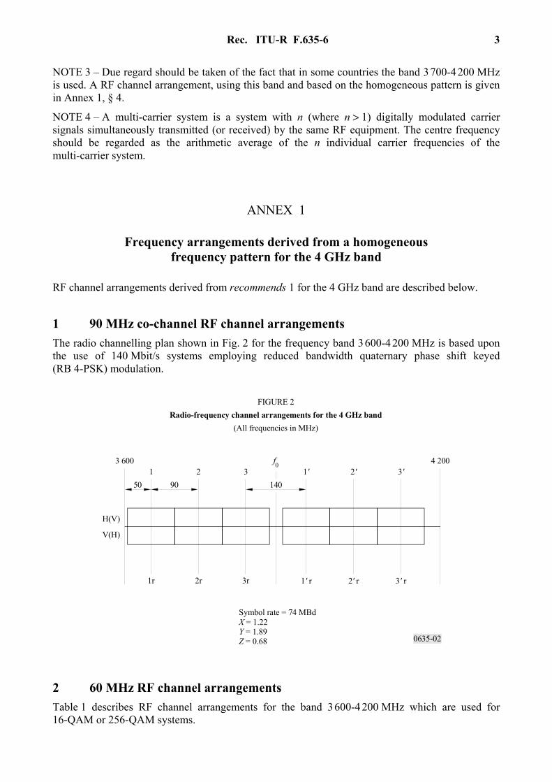
1 90 MHz co-channel RF channel arrangements The radio channelling plan shown in Fig. 2 for the frequency band 3 600-4 200 MHz is based upon the use of 140 Mbit/s systems employing reduced bandwidth quaternary phase shift keyed (RB 4-PSK) modulation.
0635-02
f0
50 90 140
2r1r 3r 1' r 2' r 3' r
1 2 3 1' 2' 3'
H(V)
V(H)
4 2003 600
FIGURE 2Radio-frequency channel arrangements for the 4 GHz band
(All frequencies in MHz)
Symbol rate = 74 MBdX = 1.22 Y = 1.89Z = 0.68
2 60 MHz RF channel arrangements Table 1 describes RF channel arrangements for the band 3 600-4 200 MHz which are used for 16-QAM or 256-QAM systems.
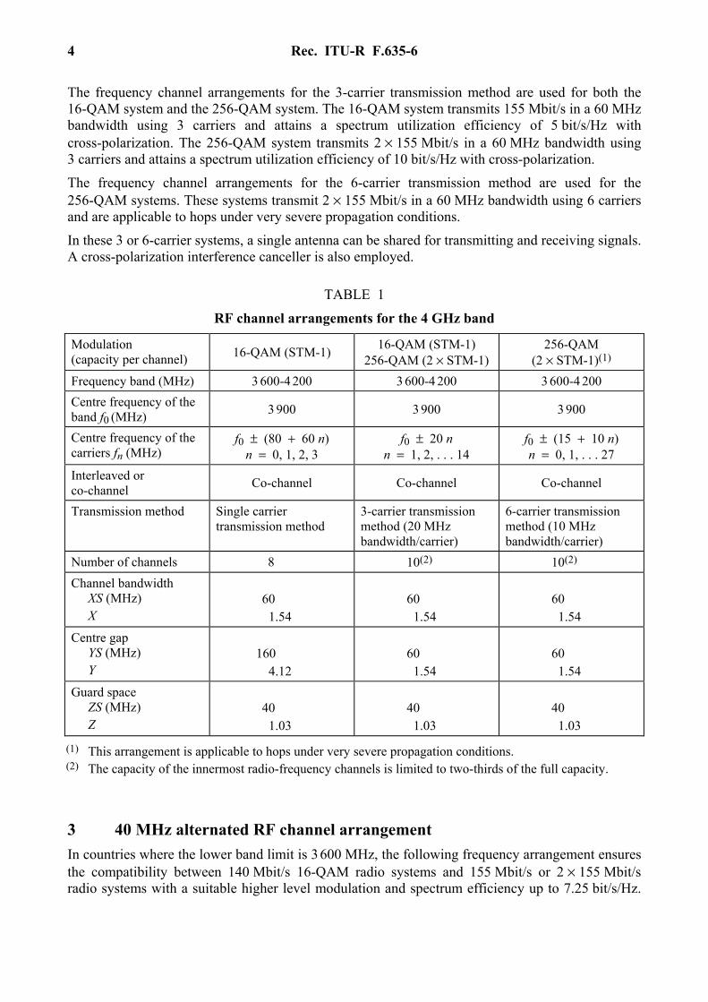
Rec. ITU-R F.635-6 4
The frequency channel arrangements for the 3-carrier transmission method are used for both the 16-QAM system and the 256-QAM system. The 16-QAM system transmits 155 Mbit/s in a 60 MHz bandwidth using 3 carriers and attains a spectrum utilization efficiency of 5 bit/s/Hz with cross-polarization. The 256-QAM system transmits 2 × 155 Mbit/s in a 60 MHz bandwidth using 3 carriers and attains a spectrum utilization efficiency of 10 bit/s/Hz with cross-polarization.
The frequency channel arrangements for the 6-carrier transmission method are used for the 256-QAM systems. These systems transmit 2 × 155 Mbit/s in a 60 MHz bandwidth using 6 carriers and are applicable to hops under very severe propagation conditions.
In these 3 or 6-carrier systems, a single antenna can be shared for transmitting and receiving signals. A cross-polarization interference canceller is also employed.
TABLE 1
RF channel arrangements for the 4 GHz band
3 40 MHz alternated RF channel arrangement In countries where the lower band limit is 3 600 MHz, the following frequency arrangement ensures the compatibility between 140 Mbit/s 16-QAM radio systems and 155 Mbit/s or 2 × 155 Mbit/s radio systems with a suitable higher level modulation and spectrum efficiency up to 7.25 bit/s/Hz.
Modulation (capacity per channel) 16-QAM (STM-1) 16-QAM (STM-1)
256-QAM (2 × STM-1) 256-QAM
(2 × STM-1)(1) Frequency band (MHz) 3 600-4 200 3 600-4 200 3 600-4 200 Centre frequency of the band f0 (MHz) 3 900 3 900 3 900
Centre frequency of the carriers fn (MHz)
f0 ± (80 + 60 n) n = 0, 1, 2, 3
f0 ± 20 n n = 1, 2, . . . 14
f0 ± (15 + 10 n) n = 0, 1, . . . 27
Interleaved or co-channel Co-channel Co-channel Co-channel
Transmission method Single carrier transmission method
3-carrier transmission method (20 MHz bandwidth/carrier)
6-carrier transmission method (10 MHz bandwidth/carrier)
Number of channels 8 10(2) 10(2) Channel bandwidth XS (MHz) X
60 1.54
60 1.54
60 1.54
Centre gap YS (MHz) Y
160 4.12
60 1.54
60 1.54
Guard space ZS (MHz) Z
40 1.03
40 1.03
40 1.03
(1) This arrangement is applicable to hops under very severe propagation conditions. (2) The capacity of the innermost radio-frequency channels is limited to two-thirds of the full capacity.
Rec. ITU-R F.635-6 5
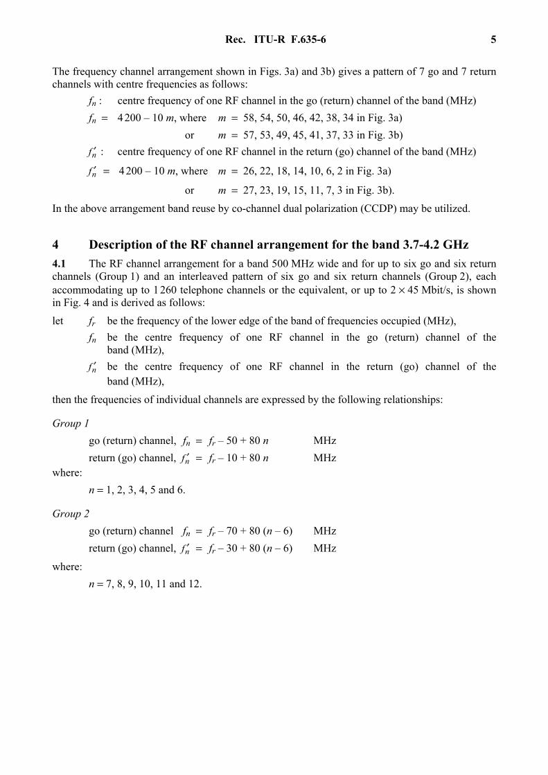
The frequency channel arrangement shown in Figs. 3a) and 3b) gives a pattern of 7 go and 7 return channels with centre frequencies as follows: fn : centre frequency of one RF channel in the go (return) channel of the band (MHz) fn = 4 200 – 10 m, where m = 58, 54, 50, 46, 42, 38, 34 in Fig. 3a) or m = 57, 53, 49, 45, 41, 37, 33 in Fig. 3b) nf ′ : centre frequency of one RF channel in the return (go) channel of the band (MHz)
nf ′ = 4 200 – 10 m, where m = 26, 22, 18, 14, 10, 6, 2 in Fig. 3a)
or m = 27, 23, 19, 15, 11, 7, 3 in Fig. 3b).
In the above arrangement band reuse by co-channel dual polarization (CCDP) may be utilized.
4 Description of the RF channel arrangement for the band 3.7-4.2 GHz 4.1 The RF channel arrangement for a band 500 MHz wide and for up to six go and six return channels (Group 1) and an interleaved pattern of six go and six return channels (Group 2), each accommodating up to 1 260 telephone channels or the equivalent, or up to 2 × 45 Mbit/s, is shown in Fig. 4 and is derived as follows:
let fr be the frequency of the lower edge of the band of frequencies occupied (MHz), fn be the centre frequency of one RF channel in the go (return) channel of the
band (MHz), nf ′ be the centre frequency of one RF channel in the return (go) channel of the
band (MHz),
then the frequencies of individual channels are expressed by the following relationships:
Group 1 go (return) channel, fn = fr – 50 + 80 n MHz return (go) channel, nf ′ = fr – 10 + 80 n MHz where: n = 1, 2, 3, 4, 5 and 6.
Group 2 go (return) channel fn = fr – 70 + 80 (n – 6) MHz return (go) channel, nf ′ = fr – 30 + 80 (n – 6) MHz
where: n = 7, 8, 9, 10, 11 and 12.
Rec. ITU-R F.635-6 6
0635-03
1 3 5 7 1' 3' 5' 7'
2 4 6 2' 4' 6'
300
3 600 3 900 4 200
3 630 3 710 3 790 3 870 3 930 4 010 4 090 4 170
3 670 3 750 3 830 3 970 4 050 4 130
40 60
XS = 40 MHzYS = 60 MHzZ S = 30 MHzZ S = 30 MHz
12
1 3 5 7 1' 3' 5' 7'
2 4 6 2' 4' 6'
320
3 600 3 900 4 200
3 620 3 700 3 780 3 860 3 940 4 020 4 100 4 180
3 660 3 740 3 820 3 980 4 060 4 140
80 80
XS = 80 MHzYS = 80 MHzZ S = 20 MHzZ S = 20 MHz
12
a)
b)
Go (Return) Return (Go)
FIGURE 3Radio-frequency channel arrangement for the 4 GHz band
(All frequencies in MHz)
Go (Return) Return (Go)
Rec. ITU-R F.635-6 7
0635-04
1080
500
1 1' 2 2' 3 3' 4 4' 5 5' 6 6'
7 7' 8 8' 9 9' 10 10' 11 11' 12 12'
3080
FIGURE 4Radio-frequency channel arrangements for the 3.7-4.2 GHz band
(All frequencies in MHz)
Channelnumber
Gro
up 1
Gro
up 2
4.2 In a section over which international connections are arranged, the go and return channels are in the same group and are adjacent channels in that group.
4.3 In any section, both the go and return channels of any one group are of one polarization.
4.4 In any section, the channels of each group are of different polarizations.
4.5 In general, the value of fr is 3 700 MHz. NOTE 1 – Subject to agreement between administrations concerned, 1 800 telephone channels may be accommodated on each RF channel using either Group 1 or Group 2 frequencies.
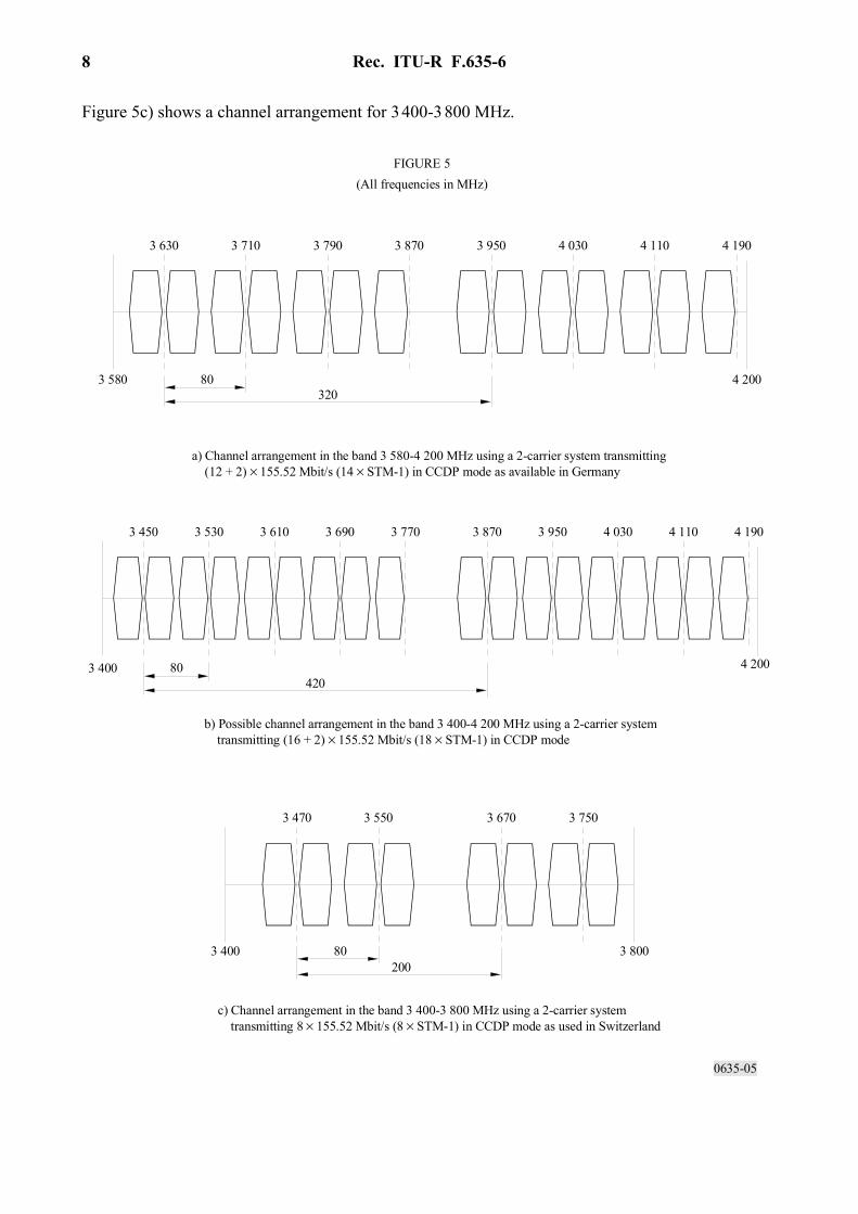
5 80 MHz CCDP channel arrangements The channel arrangements depicted in Figs. 5a), 5b), 5c) are based upon the use of a 2-carrier system transmitting 2 × 2 × 155.52 Mbit/s (4 × STM-1) via two carrier pairs using both polarizations in the CCDP mode.
The radio channelling plan shown in Fig. 5a) is optimized for the frequency band 3 580-4 200 MHz.
A channel arrangement applicable to the whole frequency band 3 400-4 200 MHz is shown in Fig. 5b).
The proposed channel arrangements shown in Figs. 5a) and 5b) use the maximum possible number of 155.52 Mbit/s signals. In addition to the quadruplets of carriers in both go and return sub-band, two pairs of cross-polar single carriers are introduced as protection channels if necessary. Due to the fact that each carrier, i.e. baseband bit stream, can be switched individually, this (n + 2)-configuration acts at least as efficient as a (n/2 + 1)-configuration when used for frequency diversity.
Rec. ITU-R F.635-6 8
Figure 5c) shows a channel arrangement for 3 400-3 800 MHz.
0635-05
4 2003 580 80320
3 630 3 710 3 790 3 870 3 950 4 030 4 110 4 190
4 2003 400 80420
3 450 3 530 3 610 3 690 3 770 4 030 4 110 4 1903 870 3 950
3 8003 400 80200
3 470 3 550 3 670 3 750
FIGURE 5(All frequencies in MHz)
a) Channel arrangement in the band 3 580-4 200 MHz using a 2-carrier system transmitting (12 + 2) × 155.52 Mbit/s (14 × STM-1) in CCDP mode as available in Germany
b) Possible channel arrangement in the band 3 400-4 200 MHz using a 2-carrier system transmitting (16 + 2) × 155.52 Mbit/s (18 × STM-1) in CCDP mode
c) Channel arrangement in the band 3 400-3 800 MHz using a 2-carrier system transmitting 8 × 155.52 Mbit/s (8 × STM-1) in CCDP mode as used in Switzerland
Rec. ITU-R F.635-6 9
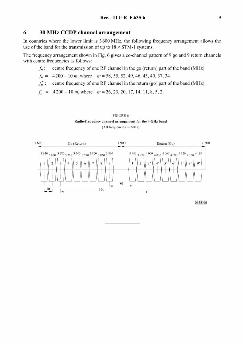
6 30 MHz CCDP channel arrangement In countries where the lower limit is 3 600 MHz, the following frequency arrangement allows the use of the band for the transmission of up to 18 × STM-1 systems.
The frequency arrangement shown in Fig. 6 gives a co-channel pattern of 9 go and 9 return channels with centre frequencies as follows: fn : centre frequency of one RF channel in the go (return) part of the band (MHz) fn = 4 200 – 10 m, where m = 58, 55, 52, 49, 46, 43, 40, 37, 34 nf ′ : centre frequency of one RF channel in the return (go) part of the band (MHz)
nf ′ = 4 200 – 10 m, where m = 26, 23, 20, 17, 14, 11, 8, 5, 2.
0635-06
1 2 4 53 6 7 8 9 1' 2' 3' 4' 5' 6' 7' 8' 9'
32080
30
3 620 3 650 3 680 3 710 3 740 3 770 3 800 3 830 3 860 3 940 3 970 4 000 4 030 4 060 4 090 4 120 4 150 4 180
3 600 3 900 4 200Return (Go)Go (Return)
FIGURE 6Radio-frequency channel arrangement for the 4 GHz band
(All frequencies in MHz)