Embed Size (px)
Citation preview
Recommendation ITU-R F.386-9(02/2013)
Radio-frequency channel arrangements forfixed wireless systems operating in the
8 GHz (7 725 to 8 500 MHz) band
F SeriesFixed service
ii Rec. ITU-R F.386-9
Foreword
The role of the Radiocommunication Sector is to ensure the rational, equitable, efficient and economical use of the radio-frequency spectrum by all radiocommunication services, including satellite services, and carry out studies without limit of frequency range on the basis of which Recommendations are adopted.
The regulatory and policy functions of the Radiocommunication Sector are performed by World and Regional Radiocommunication Conferences and Radiocommunication Assemblies supported by Study Groups.
Policy on Intellectual Property Right (IPR)
ITU-R policy on IPR is described in the Common Patent Policy for ITU-T/ITU-R/ISO/IEC referenced in Annex 1 of Resolution ITU-R 1. Forms to be used for the submission of patent statements and licensing declarations by patent holders are available from http://www.itu.int/ITU-R/go/patents/en where the Guidelines for Implementation of the Common Patent Policy for ITU-T/ITU-R/ISO/IEC and the ITU-R patent information database can also be found.
Series of ITU-R Recommendations
(Also available online at http://www.itu.int/publ/R-REC/en)
Series Title
BO Satellite delivery
BR Recording for production, archival and play-out; film for television
BS Broadcasting service (sound)
BT Broadcasting service (television)
F Fixed service
M Mobile, radiodetermination, amateur and related satellite services
P Radiowave propagation
RA Radio astronomy
RS Remote sensing systems
S Fixed-satellite service
SA Space applications and meteorology
SF Frequency sharing and coordination between fixed-satellite and fixed service systems
SM Spectrum management
SNG Satellite news gathering
TF Time signals and frequency standards emissions
V Vocabulary and related subjects
Note: This ITU-R Recommendation was approved in English under the procedure detailed in Resolution ITU-R 1.
Electronic Publication Geneva, 2013
ITU 2013
All rights reserved. No part of this publication may be reproduced, by any means whatsoever, without written permission of ITU.
Rec. ITU-R F.386-9 1
RECOMMENDATION ITU-R F.386-9
Radio-frequency channel arrangements for fixed wireless systems operating in the 8 GHz (7 725 to 8 500 MHz) band
(Question ITU-R 247/5)
(1963-1966-1982-1986-1992-1997-1999-2007-2013)
Scope
This Recommendation provides radio-frequency channel arrangements for fixed wireless systems operating in the 8 GHz (7 725 to 8 500 MHz) band, which may be used for high, medium and low capacity systems. The preferred radio-frequency channel arrangements are based on multiples of basic slots either of 3.5 MHz or 2.5 MHz width. Examples in various segments of the 8 GHz band are presented in Annexes 1 to 5. Annex 6 presents an arrangement for high capacity digital systems used in some countries.
The ITU Radiocommunication Assembly,
considering
a) that it may be desirable to be able to interconnect fixed wireless systems (FWSs) on international links at radio frequencies in the 8 GHz band;
b) that the availability of frequency bands in the range from 7 725 MHz to 8 500 MHz differs in various countries;
c) that, for some administrations, a frequency band, only 300 MHz wide or less, may be available in the 8 GHz range for such systems;
d) that some channel arrangements have been developed in the past based on analogue system requirements only;
e) that it is desirable to deploy in such a band digital systems of low, medium and/or high capacity. In some countries, analogue systems are still being used;
f) that digital systems are mostly designed to accommodate radio-frequency (RF) channel arrangements based on multiples of 2.5 MHz or 3.5 MHz patterns;
g) that, digital techniques such as cross-polar interference cancellers (XPIC) may significantly contribute to the cross-polar discrimination improvement factor (XIF, defined in Recommendation ITU-R F.746), thus counteracting multipath or rain propagation-induced depolarization;
h) that, when very high capacity links (e.g. twice Synchronous Transfer Mode-1 (STM-1)) are required, further economy may be achieved using system bandwidths wider than the recommended channel separation, associated to high-efficient modulation formats,
recommends
1 that the preferred RF channel arrangements be based on multiples of basic bandwidths of either 3.5 MHz or 2.5 MHz; examples in various segments of the 8 GHz band are shown in Annexes 1 to 5;
2 that, in a section over which the international connection is arranged, all the go channels should be in one half of the band, and all the return channels should be in the other half of the band;
2 Rec. ITU-R F.386-9
3 that, for adjacent RF channels in the same half of the band, horizontal and vertical polarization may be used alternately, as well as co-channel arrangements, provided that sufficient adjacent channel rejection is provided;
4 that when very high capacity links are required and network coordination permits, with the agreement of the administrations concerned, the use of any two adjacent 28 or 29.65 MHz channels specified in recommends 1 is possible, for wider bandwidth system, with centre frequency lying in the central point of the distance between the two 28 or 29.65 MHz adjacent channels;
5 that due regard be taken of the fact that, in some countries, in the 7 725 MHz to 8 275 MHz band, another RF channel arrangement for high capacity digital systems up to 140 Mbit/s or synchronous digital hierarchy bit rates is used. A description of this RF channel arrangement is given in Annex 6. Administrations currently using channel arrangements based on the 29.65 MHz raster are encouraged, in the future, to migrate to this more efficient 28 MHz and sub-multiples channel arrangement in Annex 2.
Annex 1
RF channel arrangements for the transmission of various digital signals operating in the 7 725-8 275 MHz band, with 300 MHz duplex spacing, based on multiples of 2.5 MHz bandwidth referred to in recommends 1
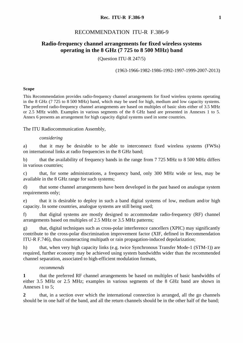
This Annex describes an RF channel arrangement for low, medium and high capacity point-to-point FWS using digital modulation and operating in the band 7 725-8 275 MHz. Channel pairs are provided with a common transmit-receive separation of 300 MHz.
1 The RF channel arrangement is shown in Fig. 1 and is derived as follows:
Let f0 be the frequency at the centre of the band:
f0 = 8 000 MHz
fn be the centre frequency of one RF channel in the lower half of the band (MHz);
nf ′ be the centre frequency of one RF channel in the upper half of the band (MHz),
then the centre frequencies of the individual channels are expressed by the following relationships:
1.1 for systems with a 30 MHz channel bandwidth:
lower half of the band: fn = f0 – 290 + 30 n MHz
upper half of the band: nf ′ = f0 + 10 + 30 n MHz
where:
n = 1, 2, 3, … 8;
1.2 for systems with a 20 MHz channel bandwidth:
lower half of the band: fn = f0 – 285 + 20 n MHz
upper half of the band: nf ′ = f0 + 15 + 20 n MHz
where:
n = 1, 2, 3, … 12;
Rec. ITU-R F.386-9 3
1.3 for systems with a 10 MHz channel bandwidth:
lower half of the band: fn = f0 – 280 + 10 n MHz
upper half of the band: nf ′ = f0 + 20 + 10 n MHz
where:
n = 1, 2, 3, … 25.
FIGURE 1
RF channel arrangements for the band 7 725-8 275 MHz
(All frequencies in MHz)
F.0386-01
………… …………………… …………
275 275f0 = 8 000
1 2 3 4 5 6 7 8 1' 2' 3' 4' 5' 6' 7' 8'
30 90
8020
300
30060
10
Channel numbers = 1, 2, 3, ...8 and 1 , 2 , 3 , ... 8' ' ' '
Channel numbers = 1, 2, 3, ...12 and 1 , 2 , 3 , ... 12' ' ' '
Channel numbers = 1, 2, 3, ...25 and 1 , 2 , 3 , ... 25' ' ' '
1 2 3 4 5 6 7 8 9 10 11 12 1' 2' 3' 4' 5' 6' 7' 8' 9' 10' 11' 12'
1 2 3 4 25 1' 2' 3' 4' 25 '
300
2 Low capacity systems with RF channel bandwidths of 1.25 MHz, 2.5 MHz and 5 MHz may also be utilized by subdividing the 10 MHz RF bandwidth pattern shown in Fig. 1.
4 Rec. ITU-R F.386-9
Annex 2
RF channel arrangements for digital FWS operating in the 7 725-8 275 and 8 275-8 500 MHz bands based on multiples of 3.5 MHz
bandwidth referred to in recommends 1
1 Channel arrangement in the frequency band 7 725-8 275 MHz
The RF channel arrangement, in a frequency band of ±275 MHz across the centre frequency 8 000 MHz for up to nine go and nine return channels, each accommodating high capacity digital systems operating in the 8 GHz band, is as shown in Fig. 2.
Narrower channels, 18 channels 14 MHz wide and 36 channels 7 MHz wide, can be obtained by subdivision of the 28 MHz main channels.
Channel pairs are provided with a common transmit-receive separation of 283.5 MHz.
The channels centre frequencies are derived as follows:
Let f0 be the frequency of the centre of the band of frequencies occupied (MHz);
fn be the centre frequency of one RF channel in the lower half of this band (MHz);
nf ′ be the centre frequency of one RF channel in the upper half of this band (MHz).
The centre frequency should be:
f0 = 8 000 MHz
then the frequencies (MHz) of individual channels are expressed by the following relationships:
1.1 28 MHz channel arrangement
The frequencies of the individual channels are expressed by the following relationships:
lower half of the band: fn = f0 – 281 + 28 n MHz
upper half of the band: nf ′ = f0 + 2.5 + 28 n MHz
where:
n = 1, 2, 3, 4, 5, 6, 7, 8 or 9.
FIGURE 2
RF channel arrangements for digital FWS operating in the 7 725-8 275 MHz band
(All frequencies in MHz)
F.0386-02
275
1 3 5 72 4 6 8 1 ' 5 '3' 7'2' 6'4 ' 8 'Channelnumber
283.5
28 59.5
9 9 '
22
275
20.5
V (H)H (V)
ƒ 8 0000 =
Rec. ITU-R F.386-9 5
1.2 14 MHz channel arrangement
The frequencies of the individual channels are expressed by the following relationships:
lower half of the band: fn = f0 – 274 + 14 n MHz
upper half of the band: nf ′ = f0 + 9.5 + 14 n MHz
where:
n = 1, 2, …… 17 or 18.
1.3 7 MHz channel arrangement
The frequencies of the individual channels are expressed by the following relationships:
lower half of the band: fn = f0 – 270.5 + 7 n MHz
upper half of the band: nf ′ = f0 + 13 + 7 n MHz
where:
n = 1, 2, …… 35 or 36.
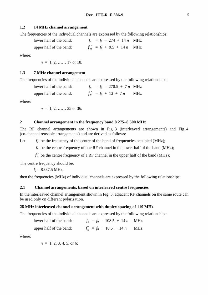
2 Channel arrangement in the frequency band 8 275−8 500 MHz
The RF channel arrangements are shown in Fig. 3 (interleaved arrangements) and Fig. 4 (co-channel reusable arrangements) and are derived as follows:
Let f0 be the frequency of the centre of the band of frequencies occupied (MHz);
fn be the centre frequency of one RF channel in the lower half of the band (MHz);
nf ′ be the centre frequency of a RF channel in the upper half of the band (MHz);
The centre frequency should be:
f0 = 8 387.5 MHz;
then the frequencies (MHz) of individual channels are expressed by the following relationships:
2.1 Channel arrangements, based on interleaved centre frequencies
In the interleaved channel arrangement shown in Fig. 3, adjacent RF channels on the same route can be used only on different polarization.
28 MHz interleaved channel arrangement with duplex spacing of 119 MHz
The frequencies of the individual channels are expressed by the following relationships:
lower half of the band: fn = f0 – 108.5 + 14 n MHz
upper half of the band: nf ′ = f0 + 10.5 + 14 n MHz
where:
n = 1, 2, 3, 4, 5, or 6;
6 Rec. ITU-R F.386-9
14 MHz interleaved channel arrangement with duplex spacing of 126 MHz
The frequencies of the individual channels are expressed by the following relationships:
lower half of the band: fn = f0 – 108.5 + 7 n MHz
upper half of the band: nf ′ = f0 + 17.5 + 7 n MHz
where:
n = 1, 2, 3, . . . 12.
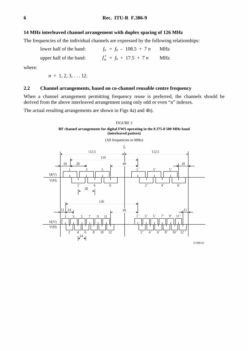
2.2 Channel arrangements, based on co-channel reusable centre frequency
When a channel arrangement permitting frequency reuse is preferred, the channels should be derived from the above interleaved arrangement using only odd or even “n” indexes.
The actual resulting arrangements are shown in Figs 4a) and 4b).
FIGURE 3
RF channel arrangements for digital FWS operating in the 8 275-8 500 MHz band (interleaved pattern)
(All frequencies in MHz)
F.0386-03
49
H(V)V(H)
V(H)
H(V)
142 4 6 8 10 12 2' 4' 12 '6' 8' 10 '
1
1411
3 5 7 9 11 1 ' 3 ' 5 ' 7' 9' 11 '
11
49
428
2
31
6
5 1 '
2 ' 4' 6'
3' 5'
182818
f0112.5 112.5
119
126
Rec. ITU-R F.386-9 7
FIGURE 4
RF channel arrangements for digital FWS operating in the 8 275-8 500 MHz band (frequency reuse pattern)
(All frequencies in MHz)
F.0386-04
H(V)V(H)
V(H)
H(V)
1
1411
3 5 7 9 11 1' 3' 5' 7 ' 9 '
18
63
31 5 1 ' 3 ' 5 '
322818
f0112.5 112.5
119
126
a) Odd channels arrangements
11'
56
H(V)
V(H)
V(H)
H(V)
2
1418
4 6 8 10 12 2 4 6 8 10
11
63
42 6 2' 4' 6 '
182832
f0112.5 112.5
119
126
b) Even channels arrangements
56
12
NOTE 1 – When using in the same area channel 1 of the 28 MHz arrangements of the 8 275-8 500 MHz band and channel 8’ of the 29.65 MHz arrangement of the 7 725-8 275 MHz band in Annex 6, care should be taken to their separation of 26.43 MHz only, therefore, those two channels cannot be used on the same link.
8 Rec. ITU-R F.386-9
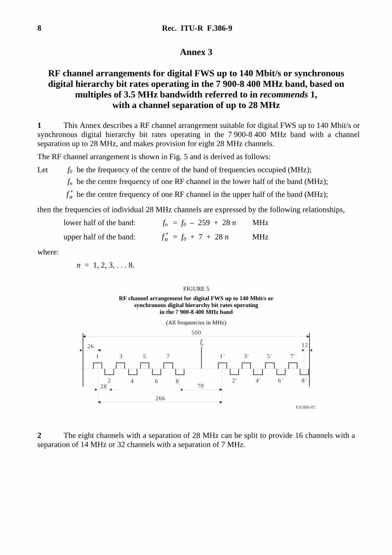
Annex 3
RF channel arrangements for digital FWS up to 140 Mbit/s or synchronous digital hierarchy bit rates operating in the 7 900-8 400 MHz band, based on
multiples of 3.5 MHz bandwidth referred to in recommends 1, with a channel separation of up to 28 MHz
1 This Annex describes a RF channel arrangement suitable for digital FWS up to 140 Mbit/s or synchronous digital hierarchy bit rates operating in the 7 900-8 400 MHz band with a channel separation up to 28 MHz, and makes provision for eight 28 MHz channels.
The RF channel arrangement is shown in Fig. 5 and is derived as follows:
Let f0 be the frequency of the centre of the band of frequencies occupied (MHz);
fn be the centre frequency of one RF channel in the lower half of the band (MHz);
nf ′ be the centre frequency of one RF channel in the upper half of the band (MHz);
then the frequencies of individual 28 MHz channels are expressed by the following relationships,
lower half of the band: fn = f0 – 259 + 28 n MHz
upper half of the band: nf ′ = f0 + 7 + 28 n MHz
where:
n = 1, 2, 3, . . . 8.
FIGURE 5
RF channel arrangement for digital FWS up to 140 Mbit/s or synchronous digital hierarchy bit rates operating
in the 7 900-8 400 MHz band
(All frequencies in MHz)
F.0386-05
1 5 73 1 ' 3' 5' 7'
2 84 6 2' 4' 6 ' 8 '
f0
70
500
28
26 12
266
2 The eight channels with a separation of 28 MHz can be split to provide 16 channels with a separation of 14 MHz or 32 channels with a separation of 7 MHz.
Rec. ITU-R F.386-9 9
The frequencies of individual channels are expressed by the following relationships:
2.1 for 14 MHz channels:
lower half of the band: fn = f0 – 259 + 14 n MHz
upper half of the band: nf ′ = f0 + 7 + 14 n MHz
where:
n = 1, 2, 3, . . . 16.
2.2 for 7 MHz channels:
lower half of the band: fn = f0 – 252 + 7 n MHz
upper half of the band: nf ′ = f0 + 14 + 7 n MHz
where:
n = 1, 2, 3, . . . 32.
3 The centre frequency f0 is 8 157 MHz.
Annex 4
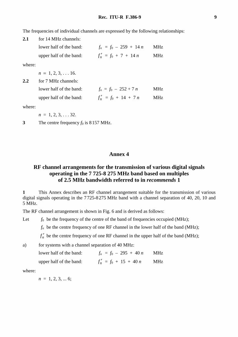
RF channel arrangements for the transmission of various digital signals operating in the 7 725-8 275 MHz band based on multiples
of 2.5 MHz bandwidth referred to in recommends 1
1 This Annex describes an RF channel arrangement suitable for the transmission of various digital signals operating in the 7 725-8 275 MHz band with a channel separation of 40, 20, 10 and 5 MHz.
The RF channel arrangement is shown in Fig. 6 and is derived as follows:
Let f0 be the frequency of the centre of the band of frequencies occupied (MHz);
fn be the centre frequency of one RF channel in the lower half of the band (MHz);
nf ′ be the centre frequency of one RF channel in the upper half of the band (MHz);
a) for systems with a channel separation of 40 MHz:
lower half of the band: fn = f0 – 295 + 40 n MHz
upper half of the band: nf ′ = f0 + 15 + 40 n MHz
where:
n = 1, 2, 3, ... 6;
10 Rec. ITU-R F.386-9
b) for systems with a channel separation of 20 MHz:
lower half of the band: fn = f0 – 275 + 20 n MHz
upper half of the band: nf ′ = f0 + 35 + 20 n MHz
where:
n = 1, 2, 3, ... 11;
c) for systems with a channel separation of 10 MHz:
lower half of the band: fn = f0 – 275 + 10 n MHz
upper half of the band: nf ′ = f0 + 35 + 10 n MHz
where:
n = 1, 2, 3, ... 23;
d) for systems with a channel separation of 5 MHz:
lower half of the band: fn = f0 – 275 + 5 n MHz
upper half of the band: nf ′ = f0 + 35 + 5 n MHz
where:
n = 1, 2, 3, ... 47.
The centre frequency f0 is 8 000 MHz.
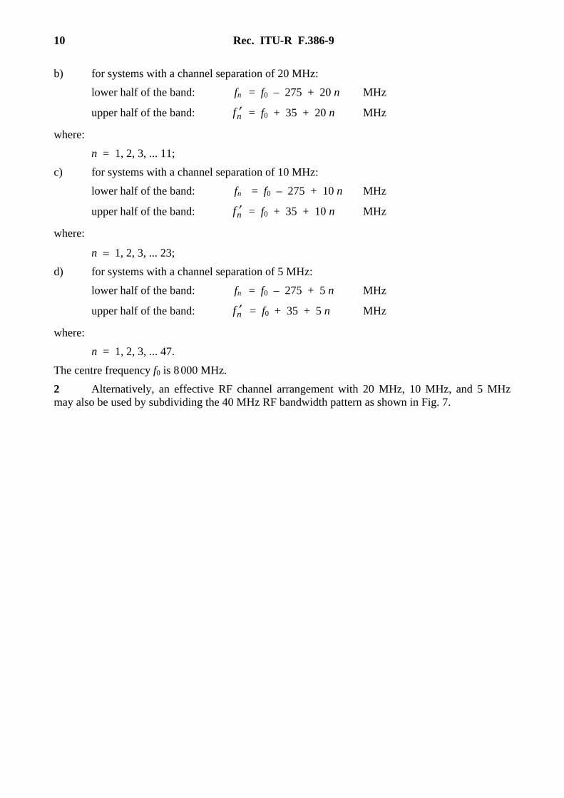
2 Alternatively, an effective RF channel arrangement with 20 MHz, 10 MHz, and 5 MHz may also be used by subdividing the 40 MHz RF bandwidth pattern as shown in Fig. 7.
Rec. ITU-R F.386-9 11
FIGURE 6
RF channel arrangements for transmission of various signals operating with 40 MHz, 20 MHz, 10 MHz and 5 MHz channel
spacing in 7 725-8 275 band
(All frequencies in MHz)
F.0386-06
275 275
f01 2 3 6 1' 2 ' 3' 6'
110
a) for systems with a carrier spacing of 40 MHz
20 40 40 20
310
275 275
f01 2 3 11 1' 2' 3 ' 11'
90
b) for systems with a carrier spacing of 20 MHz
20 20 20 20
310
275 275
f01 2 3 23 1 ' 2' 3 ' 23'
90
c) for systems with a carrier spacing of 10 MHz
10 10 10 10
310
275 275
f01 2 3 47 1' 2' 3' 47'
80
d) for systems with a carrier spacing of 5 MHz
5 5 5 5
310
12 Rec. ITU-R F.386-9
FIGURE 7
Alternative RF channel arrangements for transmission of various digital signals operating with 40 MHz, 20 MHz, 10 MHz and 5 MHz channel spacing
in the band 7 725-8 275 MHz
F.0386-07
7.725 GHz
1 2 6 1' 2 ' 6 '
110 MHz
a) for systems with a carrier spacing of 40 MHz
40 MHz
310 MHz
8.275 GHz
7.745 7.785 7.795 8.000 8.055 8.095 8.255
1 2 1' 3 ' 11'
90 MHz
b) for systems with a carrier spacing of 20 MHz
20 MHz
310 MHz
7.735 7.795 7.955 8.000 8.045 8.105 8.265
3 4 11 12 2 ' 4 ' 12'
8.2458.0858.0657.9357.7757.755
1 2 1' 3' 18 '
80 MHz
c) for systems with a carrier spacing of 10 MHz
10 MHz
310 MHz
7.730 7.790 7.960 8.000 8.040 8.210
3 4 22 24 2 ' 4 '
8.0607.9207.7707.750 8.230 8.250 8.270
5 6 7 8 20' 22 ' 24 '
75 MHz
d) for systems with a carrier spacing of 5 MHz
5 MHz
310 MHz
7.9625 8.000 8.0373 8.2725
Rec. ITU-R F.386-9 13
Annex 5
RF channel arrangements for digital FWS operating in the 8 025 to 8 500 MHz band based on multiples of 3.5 MHz
bandwidth referred to in recommends 1
This Annex describes an RF channel arrangement suitable for digital FWS operating in the 8 025-8 500 MHz band with a channel separation multiple of 3.5 MHz.
The RF channel arrangement is shown in Fig. 8 and is derived as follows:
Let fn be the centre frequency of one RF channel in the lower half of the band (MHz);
nf ′ be the centre frequency of one RF channel in the upper half of the band (MHz);
f0 be the reference frequency (MHz),
f0 = 8 253 MHz
a) for systems with a channel separation of 28 MHz (32 × 2 Mbit/s):
lower half of the band: fn = f0 – 217 + 28 n MHz
upper half of the band: nf ′ = f0 – 9 + 28 n MHz
where:
n = 2, 3, . . . 7;
b) for systems with a channel separation of 14 MHz (16 × 2 Mbit/s):
lower half of the band: fn = f0 – 210 + 14 n MHz
upper half of the band: nf ′ = f0 – 2 + 14 n MHz
where:
n = 2, 3, . . . 14;
c) for systems with a channel separation of 7 MHz (8 × 2 Mbit/s):
lower half of the band: fn = f0 – 206.5 + 7 n MHz
upper half of the band: nf ′ = f0 + 1.5 + 7 n MHz
where:
n = 3, 4, . . . 28.
14 Rec. ITU-R F.386-9
FIGURE 8
RF channel arrangements for transmission of digital FWS operating with multiples of 3.5 MHz channel spacing
in the band 8 025-8 500 MHz
(All frequencies in MHz)
F.0386-08
175 201
f02 3 4 7 2' 3' 4' 7 '
21
a) for systems with a carrier spacing of 28 MHz
14 28 28 14
208
189 201
f0
14
b) for systems with a carrier spacing of 14 MHz
7 14 14 7
208
68
40
2 3 4 14 2' 3' 4 ' 14 '
189 201
f0
10.5
c) for systems with a carrier spacing of 7 MHz
3.5 7 7 3.5
208
33
3 4 5 28 3' 4' 5 ' 28 '
Annex 6
Description of the RF channel arrangement referred to in recommends 5
1 The RF channel arrangement, in a frequency band of ±275 MHz across the centre frequency 8 000 MHz for up to eight go and eight return channels, each accommodating high capacity digital systems up to 140 Mbit/s or synchronous digital hierarchy bit rates operating in the 8 GHz band, is as shown in Fig. 9 and is derived as follows:
Let f0 be the frequency of the centre of the band of frequencies occupied (MHz);
fn be the centre frequency of one RF channel in the lower half of this band (MHz);
Rec. ITU-R F.386-9 15
nf ′ be the centre frequency of one RF channel in the upper half of this band (MHz);
then the frequencies of the individual channels are expressed by the following relationships:
lower half of the band: fn = f0 – 281.95 + 29.65 n MHz
upper half of the band: nf ′ = f0 + 29.37 + 29.65 n MHz
where:
n = 1, 2, 3, 4, 5, 6, 7 or 8.
FIGURE 9
RF channel arrangements for digital FWS with capacities up to 140 Mbit/s or synchronous digital hierarchy bit rates operating
in the 7 725-8 275 MHz band
(All frequencies in MHz)
F.0386-09
1 5 73 1' 3 ' 5' 7 '
2 84 6 2' 4 ' 6' 8'
f0
29.65 103.77
311.32
275 275
Channelnumber
2 In a section over which the international interconnection is arranged, all the go channels should be in one half of the band, and all the return channels should be in the other half of the band.
3 The go and return channels on a given section should preferably use the polarizations shown below:
Go Return
H(V) 1 3 5 7 1′ 3′ 5′ 7′ V(H) 2 4 6 8 2′ 4′ 6′ 8′
4 When additional RF channels, interleaved between those of the main pattern, are required, the values of the centre frequencies of these RF channels should be 14.825 MHz below those of the corresponding main channel frequencies.
5 In the case of digital FWS with a co-channel arrangement, the plan as shown in Fig. 10, should be used.
16 Rec. ITU-R F.386-9
FIGURE 10
Co-channel arrangement for digital FWS operating in the 7 725-8 275 MHz band
(All frequencies in MHz)
F.0386-10
275 275
1 5 7 1' 3 ' 5' 7 '
2 4 6 2' 4 ' 8'8
f0
Channelnumber
29.65 103.77
311.32
3
6'
6 That, for international connections, the centre frequency should be:
f0 = 8 000 MHz
This value corresponds to the band 7 725-7 975 MHz in the lower half and 8 025-8 275 MHz in the upper half.
NOTE 1 – The RF channel arrangement shown in Fig. 9 overlaps that mentioned in Recommendation ITU-R F.385, for a centre frequency of 7 700 MHz, by 125 MHz between 7 725 MHz and 7 850 MHz. All due precautions to avoid mutual interference must be taken by FWS using these channel arrangements.


![ITU-T Y - IETF · [ITU-T H.248.1] Recommendation ITU-T H.248.1, Gateway control protocol: Version 3. [ITU-T H.460.4] Recommendation ITU-T H.460.4, Call priority designation and country/international](https://img.pdfslide.us/doc/110x75/5f1ddf16a7faaa7d93495e0f/itu-t-y-ietf-itu-t-h2481-recommendation-itu-t-h2481-gateway-control-protocol.jpg)