Embed Size (px)
Citation preview
Contact: A.C. Morton, Vice-Chairman and
Rapp. Q17
AT&T
USA
Tel: +1 732 420 1571
Fax:
Email: [email protected]
Attention: This is not a publication made available to the public, but an internal ITU-T Document intended only for use by the
Member States of ITU, by ITU-T Sector Members and Associates, and their respective staff and collaborators in their ITU related
work. It shall not be made available to, and used by, any other persons or entities without the prior written consent of ITU-T.
INTERNATIONAL TELECOMMUNICATION UNION STUDY GROUP 12
TELECOMMUNICATION
STANDARDIZATION SECTOR
STUDY PERIOD 2013-2016
TD 862 r1 (GEN/12)
English only
Original: English
Question(s): 17/12, 12/12, 13/12 Geneva, January 2016
TD
Source: Study Group 12
Title: Last Call Comments on the Last Call Text of – Draft new Recommendation ITU-T
Q. 3960 (formerly Q.FW_Int_sp_test) “Framework of Internet speed measurements
for the fixed and mobile networks” (Geneva, 2-11 December 2015)
Notes
This document contains the comments on the Consented version of Q. 3960 (formerly
Q.FW_Int_sp_test) agreed at the SG 12 meeting as described above.
- 2 -
TD 862 r1 (GEN/12)
INTERNATIONAL TELECOMMUNICATION UNION
ITU-Т Series Q STANDARDIZATION SECTOR (mm/yyyy)
SERIES Q: SWITCHING AND SIGNALLING[ACM1]
Recommendation ITU Q.FW_Int_sp_test
Framework of Internet speed measurements for the fixed and mobile networks
- 3 -
TD 862 r1 (GEN/12)
Content
1. Motivation ..................................................................................................................... 4
1.1. Disadvantages of the existing methods of data speed measurement ............................ 4
2. Scope ............................................................................................................................. 5
3. References ..................................................................................................................... 5
4. Definitions .................................................................................................................... 6
5. Abbreviations ................................................................................................................ 6
6. Conventions .................................................................................................................. 6
7. Measurement tests definition ........................................................................................ 6
8. Basic concept ................................................................................................................ 7
9. Test Facilities ................................................................................................................ 8
9.1 Controller requirements ................................................................................................ 9
9.2 Collector requirements .................................................................................................. 9
9.3 Measurement Agent requirements ................................................................................ 9
9.4 Measurement Peers requirements ................................................................................. 9
10. Architecture of the measurement system ...................................................................... 10
11. Workflow ...................................................................................................................... 11
12. Test parameters ............................................................................................................. 16
- 4 -
TD 862 r1 (GEN/12)
1. Motivation
The customer’s estimation of the quality of Internet access is based on the different parameters such
as the latency of access to the Internet resource (e.g. time for opening a web page), the bit rate of
access to the Internet resource (e.g. the download speed), etc. All tThese and many other parameters
[Y.1540] characterize the performance of networks and directly influence the opinion of customers
about the quality of the Internet connection provided by fixed and mobile operators. However, the
chain of access to the Internet resources is not limited by telecom operators and includes also internet
service providers, content service providers, because the Internet is a system of computer networks
providing worldwide connectivity among users and information sourcesetc. Moreover, tTelecom
operators (fixed and mobile) may advertise the Interneta speed associated with the local connection
which in the most cases is not guaranteed between all hosts on the Internet. As a result of all above
facts customers are disappointed.[ACM2]
In this regard, the development of unified approach to measure the access speed to the Internet as
well as an access speed to the Internet resources can become one of the most important issues for all
ICT players (e.g. operators, regulators, Internet community, etc.) and especially for customers.
For the time being there are many different ways to assess the rate of Internet speed but most of them
are based on the estimation of speed between a customer and a server which belongs not to telecom
operator or Regulator and located somewhere in Internet, in most cases outside of the customer’s
country (e.g. speedtest.net, netztest.at, velocimetro.org, etc.). Also, there are currently no
standardized metrics for Internet speed in the Recommendations of the ITU-T, and this topic is under
study.
This Recommendation describes test framework for Internet speed measurement, it was therefore
designed targeting the end users of the fixed and mobile networks for the assessment of the Internet
speed connection. Also it may be used by Regulators/Operators for the assessment of the Internet
speed connection at the national level.
The proposed framework has been developed on the basis of other standards trying to comply with
any existing regulation.
1.1. Disadvantages of the existing methods of data speed measurement
The existing Internet speed measurement systems which are made publically available in the Internet
have several issues which do not allow customers to get the reliable measurement results and
operators to use it as a part of Service Level Agreement (SLA)[ACM3]. Beyond the lack of standardized
metrics for Internet speed in the Recommendations of the ITU-T, tThere are the following issues:
the obtained test results, which were achieved by one testing method, may vary from results
achieved by other one. Obviously, the testing results depend on the amount of the network
segments which were used during a peer-to-peer testing (not guarantee that a peer-to-peer
connection is based on telecom operator’s network only and does not include other Internet
segments);
the results of measurements might be impacted to one or more of the following factors:
overload of the measured server and its capabilities;
hardware configuration and performance of the customer’s equipment;
the installed software (e.g. operating system, applications, etc.) and/or available
performance of the user's terminal at the time of measurement;
network performance (e.g. busy hour) and the level of utilization of customer’s
interface connected to the Internet at the time of measurement;
activated security software and hardware (e.g. firewalls, anti-virus, etc.) at the time of
measurement;
- 5 -
TD 862 r1 (GEN/12)
differentiated treatment due to recognizing the measurement flows to increase the
performance experienced;
private network performance between the end-user and the service interface may
reduce the overall performance measured (operator and user networks combined);
there are many more factors, including DNS connectivity, DoS attack on the tested
path, routing (interior and exterior), issues with MTU size and resulting fragmention.
end-users may generate traffic during a measurement and negatively influence the
measurement result, and this may take place without the knowledge of the measuring user as
it may be from background applications or other authorized users on the same connection.
for increasing accuracy some of the existing methods perform the set of random testing
attempts at the different time, but the testing schedule does not take into account the busy
hour;
some test methods drop around 40% of the measurement results, which does not allow ICT
players to get a reliable result.
Keywords
Internet, testing, measurement of QoS, network performance, QoE
2. Scope
This Recommendation describes the framework of Internet speed quality measurement which can be
established at the national or international level, providing customers of the existing telecom
operator’s networks the possibility to estimate the access speed to the Internet and to the Internet
resources[ACM4].
This Recommendation describes test framework for Internet speed measurement, it was therefore
designed targeting the end users of the fixed and mobile networks for the assessment of the Internet
speed connection. Also it may be used by Regulators/Operators for the assessment of the Internet
speed connection at the national level. [ACM5]The framework will support providing transparent, trust-
based measurement results which can be used by all ICT players (e.g. user, regulator, operator, ISP,
etc.).[ACM6]
The recommendation provides the architecture of the measurement framework, measurement
parameters and measurement procedure[ACM7] which should be used on the fixed and mobile operators
to estimate the access speed to the Internet resources.
The requirements for the measurement algorithm are a subject of a separate ITU-T Recommendation.
3. References
[ETSI EG 202 057-4] ETSI Guide 202 057-4 (2008), Speech processing, transmission and Quality
aspects (STQ); User related QoS parameter definitions and measurements;
Part 4. V1.2.1.
[ETSI TS 103 222-1] ETSI Technical Specification 103 222-1 (2015), Speech and multimedia
Transmission Quality (STQ); Speech and multimedia Transmission Quality
(STQ); Reference benchmarking, background traffic profiles and KPIs; Part
1: Reference benchmarking, background traffic profiles and KPIs for VoIP
and FoIP in fixed networks.
[ETSI EG 202 009-2] ETSI Guide 202 009-2 (2014), Quality of telecom services; Part 2: User
related indicators on a service specific basis.
- 6 -
TD 862 r1 (GEN/12)
[ITU-T Y.1541] Recommendation ITU-T Y.1541 (2011), Network performance objectives for
IP-based services.
[ITU-T G.1050] Recommendation ITU-T G.1050 (2011), Network model for evaluating
multimedia transmission performance over Internet Protocol.[ACM8]
[IETF RFC 2681] IETF RFC 2681 (1999), A Round Trip Delay Metric for IPPM.
[BBF TR-304] BBF Technical Report 304 (2015), Broadband Access Service Attributes and
Performance Metrics.
4. Definitions
Data Transmission Speed: the data transmission rate that is achieved separately for downloading
and uploading specified test files between a remote web site and a user's computer.
Internet Service Provider (ISP): organization that provides users with an Internet access.
Telecom operator: an organization responsible for identification and management of
telecommunication network used wholly or partly for the provision of publicly available
telecommunication services.[ACM9]
Internet Exchange Point: is a key locale for interconnection and exchange of traffic – technical
facilities where all Internet players interconnect directly with each other. (World
Telecommunication/ICT Policy Forum Geneva, Switzerland, 14-16 May 2013, backgrounder-wtpf-
13-ixps-en.htm)
5. Abbreviations
BDP Bandwidth-Delay Product
CDN Content Data Network
IR Internet Resource
ISP Internet Service Providers
MA Measurement Agent
MP Measurement Peer
RTT Round-Trip Time
SLA Service Level Agreement
6. Conventions
None
7. Measurement tests definition
Two different types of measurement tests are proposed for the estimation of Internet speed quality.
The first one considers the operator network itself. The second one considers the whole access speed
to the Internet resource, since this measurement may be closer to the Internet speed quality as
perceived by user.
The definitions of each of these measurements are next detailed:
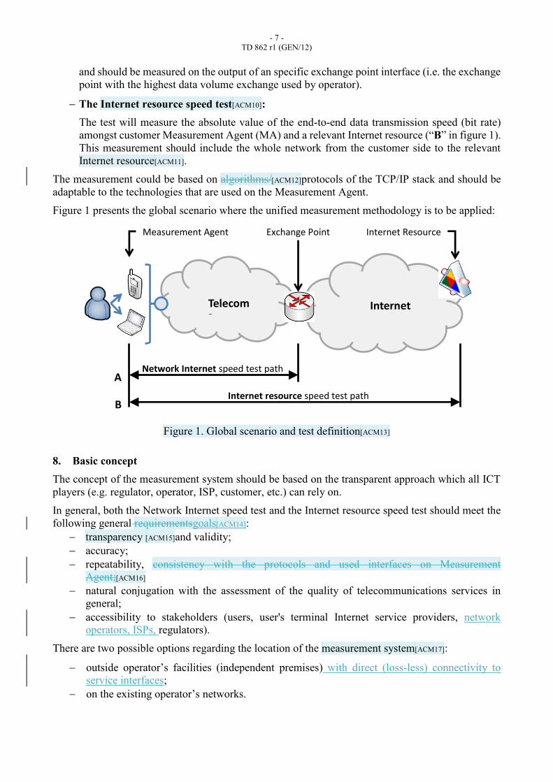
Network Internet speed test: This test will measure the absolute value of the end-to-end data transmission speed (bit rate)
between customer Measurement Agent (MA) and an external interface of exchange point
(peering point) (“A” in figure 1). This measurement should include the whole operator’s
network (access, transport, service control segments) up to the exchange point (peering point)
- 7 -
TD 862 r1 (GEN/12)
and should be measured on the output of an specific exchange point interface (i.e. the exchange
point with the highest data volume exchange used by operator).
The Internet resource speed test[ACM10]:
The test will measure the absolute value of the end-to-end data transmission speed (bit rate)
amongst customer Measurement Agent (MA) and a relevant Internet resource (“B” in figure 1).
This measurement should include the whole network from the customer side to the relevant
Internet resource[ACM11].
The measurement could be based on algorithms/[ACM12]protocols of the TCP/IP stack and should be
adaptable to the technologies that are used on the Measurement Agent.
Figure 1 presents the global scenario where the unified measurement methodology is to be applied:
Figure 1. Global scenario and test definition[ACM13]
8. Basic concept
The concept of the measurement system should be based on the transparent approach which all ICT
players (e.g. regulator, operator, ISP, customer, etc.) can rely on.
In general, both the Network Internet speed test and the Internet resource speed test should meet the
following general requirementsgoals[ACM14]:
transparency [ACM15]and validity;
accuracy;
repeatability, consistency with the protocols and used interfaces on Measurement
Agent;[ACM16]
natural conjugation with the assessment of the quality of telecommunications services in
general;
accessibility to stakeholders (users, user's terminal Internet service providers, network
operators, ISPs, regulators).
There are two possible options regarding the location of the measurement system[ACM17]:
outside operator’s facilities (independent premises) with direct (loss-less) connectivity to
service interfaces;
on the existing operator’s networks.
Telecom Operator
Internet
Measurement Agent Internet Resource Exchange Point
Network Internet speed test path
Internet resource speed test path
A
B
- 8 -
TD 862 r1 (GEN/12)
The measurement system might be implemented at the national and/or international level, providing
access to the particular measurement results to ICT players whether they connected.[ACM18]
The implementation on the international level is a preferred solution for the assessment of the Internet
resource speed, due to the following reasons:
accuracy of measurements – all measurements will be conducted from one Internationally
recognized physical entity connected to the Internet;
comprehensive analyses of user´s hardware and software – a centralized possibility to inform
customers about unsuitable configuration if detected or other configuration problems that may
lead to unreliable measurements (see Annex A);
global visualization of measured results – customers can compare “tariff/offer” advertised by
telecom operators;
differentiated tariffs for OTT services – a possibility to set up tariffs for OTT services
provided on the fixed and mobile networks.[ACM19]
In spite of the location, all involved ICT players must have the comprehensive access to the features
of the measurement system in accordance with their rights. At least each of them has to get access to
the measurement data.
9. Test Facilities
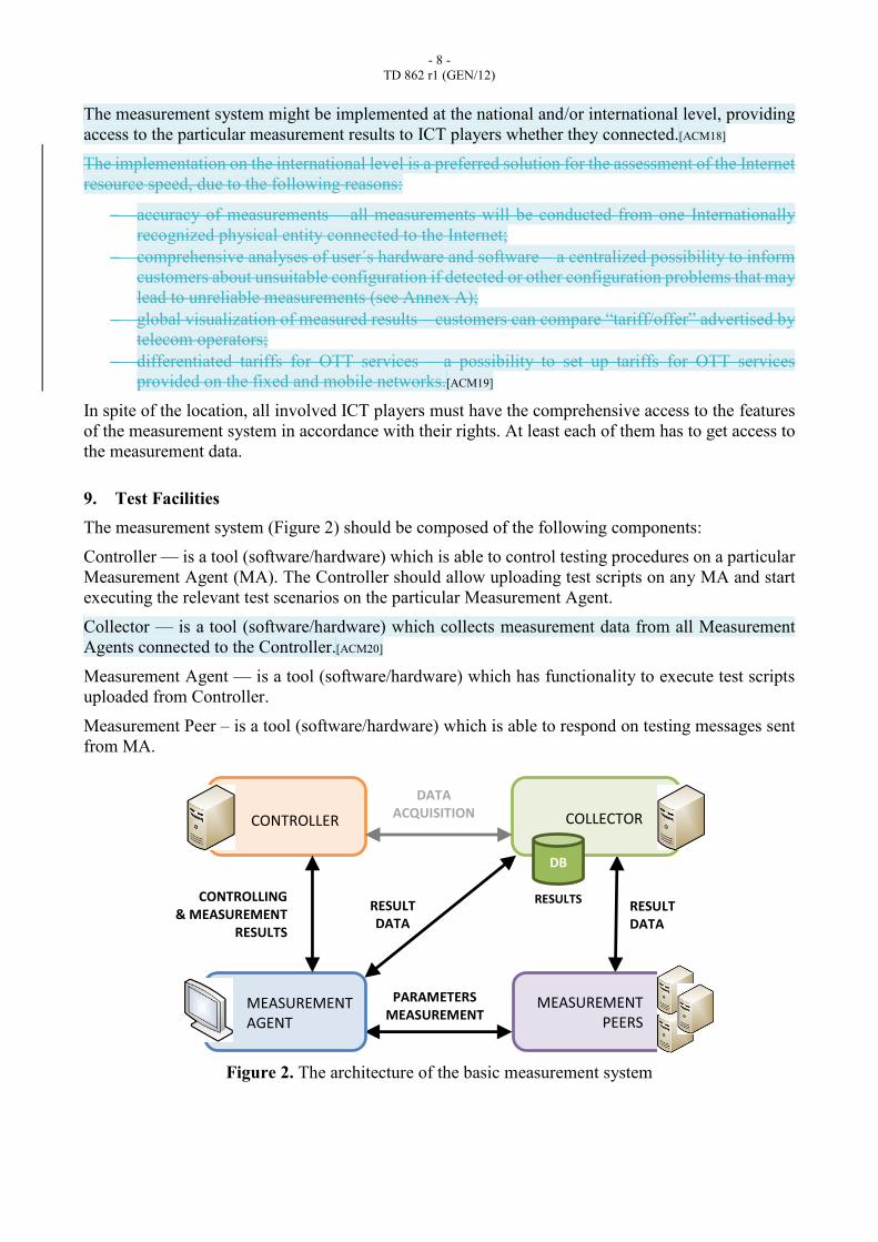
The measurement system (Figure 2) should be composed of the following components:
Controller — is a tool (software/hardware) which is able to control testing procedures on a particular
Measurement Agent (MA). The Controller should allow uploading test scripts on any MA and start
executing the relevant test scenarios on the particular Measurement Agent.
Collector — is a tool (software/hardware) which collects measurement data from all Measurement
Agents connected to the Controller.[ACM20]
Measurement Agent — is a tool (software/hardware) which has functionality to execute test scripts
uploaded from Controller.
Measurement Peer – is a tool (software/hardware) which is able to respond on testing messages sent
from MA.
Figure 2. The architecture of the basic measurement system
RESULT DATA
CONTROLLER
RESULTS
MEASUREMENT PEERS
DB
PARAMETERS MEASUREMENT
COLLECTOR
RESULT DATA
MEASUREMENT AGENT
CONTROLLING & MEASUREMENT
RESULTS
DATA ACQUISITION
- 9 -
TD 862 r1 (GEN/12)
9.1 Controller requirements[ACM21]
The Controller provides the user with the measurement environment and tools to execute the test
throughout a web page or a HTTP/s access. Therefore, the next requirements must be considered:
- It must be capable of hosting and serving the required scripts and contents to be used during the
test. Ports 80 and/or 443 should be open for this matter.
- It can coexist with the Collector within the same device. In that case, the Collector requirements
also apply to this server.
- It must not coexist with a Measurement Peer (MP) within the same device in order not to interfere
with the test itself. Measurement Peers are already high requirement devices.
9.2 Collector requirements[ACM22]
This facility shares many of the requirements with the Controller:
- It must not coexist with a Measurement Peer within the same equipment in order not to interfere
with the test itself.
As well as some additional features:
- The server should be capable of handling ciphered transmissions of data.
- It must be capable of handling, processing and storing results and other statistical data.
9.3 Measurement Agent requirements[ACM23]
The Measurement Agent may well admit two different configurations.
Option a) involves a Customer Equipment (CE) only (computer, smartphone, tablet, etc.) physically
controlled and generally owned by the user.
- This customer equipment has no specific requirements other than having an active internet
connection and a browser in order to access the site hosted at the Controller, or a preinstalled app
to access the test in case of being a portable device.
- The customer equipment should be also capable of establishing ciphered communications with
any of the other equipment of the facilities, and especially with[ACM24] the Collector, for the safe
transfer of results and other statistical data.
Option b) involves the same Customer Equipment (CE) and the existence of a Measurement Agent
(MA) in the form of a middlebox (probe) or additional hardware integrated in the CE[ACM25].
- The same customer equipment requirements are applicable to the local Measurement Peer in
the form of a middlebox or additional attached hardware.
- The local Measurement Peer also requires any hardware and software that enables the remote
management and configuration of the device without requiring any specific operation from
the customer.
9.4 Measurement Peers requirements
The Measurement Peers are the most demanding facilities in terms of network conditions. Each
device has this requirement:
- It requires proper dimensioning in terms of HW/SW and link capacity to take into account
interference amongst concurrent tests. Additionally, it must provide resource usage monitoring
- 10 -
TD 862 r1 (GEN/12)
capabilities so that the Controller could schedule tests as to prevent any foreseeing interference
impacting tests results.
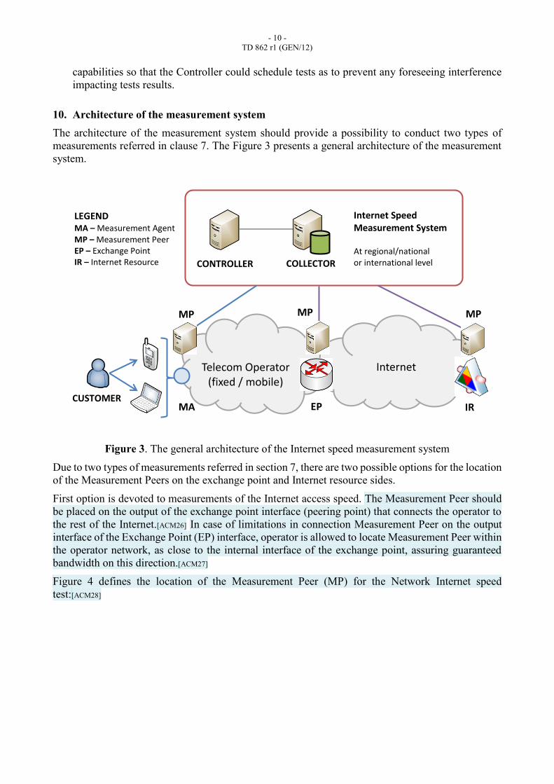
10. Architecture of the measurement system
The architecture of the measurement system should provide a possibility to conduct two types of
measurements referred in clause 7. The Figure 3 presents a general architecture of the measurement
system.
Figure 3. The general architecture of the Internet speed measurement system
Due to two types of measurements referred in section 7, there are two possible options for the location
of the Measurement Peers on the exchange point and Internet resource sides.
First option is devoted to measurements of the Internet access speed. The Measurement Peer should
be placed on the output of the exchange point interface (peering point) that connects the operator to
the rest of the Internet.[ACM26] In case of limitations in connection Measurement Peer on the output
interface of the Exchange Point (EP) interface, operator is allowed to locate Measurement Peer within
the operator network, as close to the internal interface of the exchange point, assuring guaranteed
bandwidth on this direction.[ACM27]
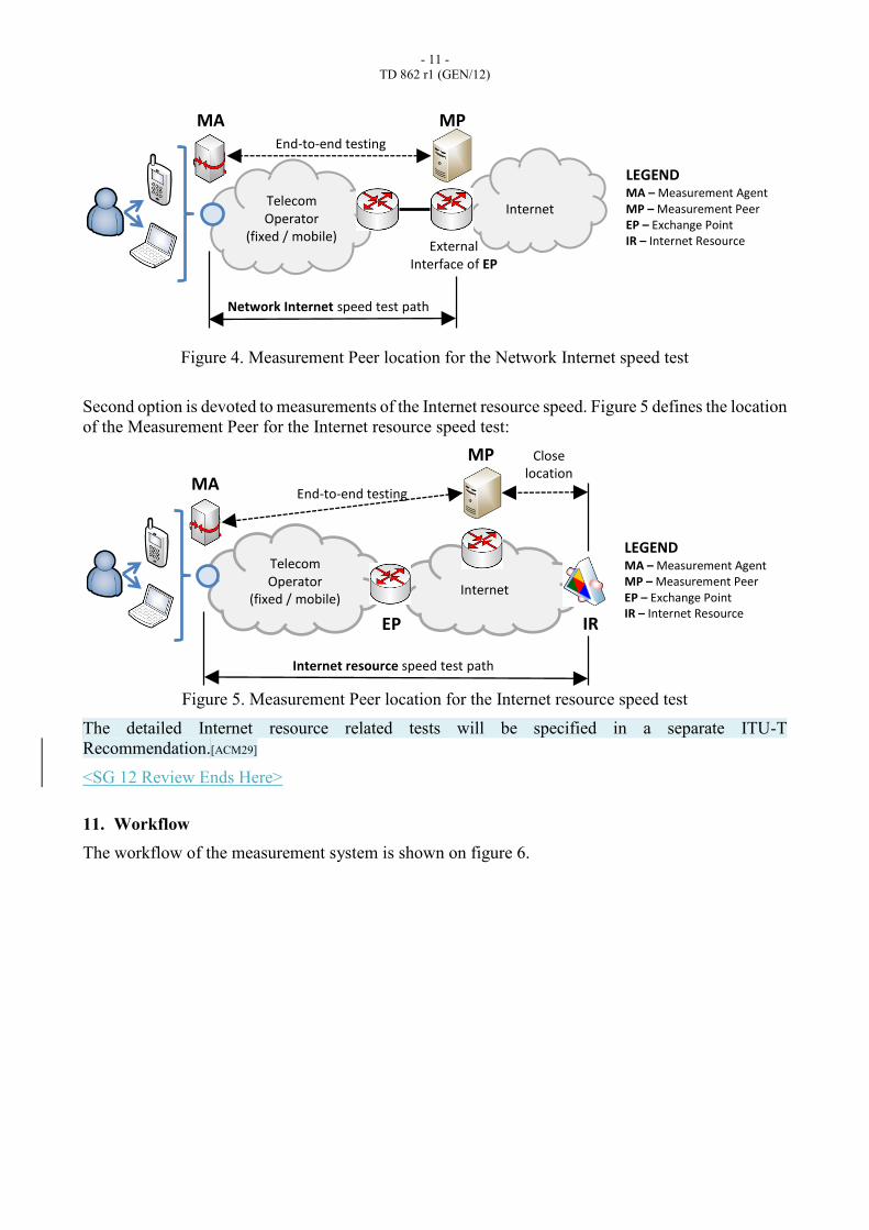
Figure 4 defines the location of the Measurement Peer (MP) for the Network Internet speed
test:[ACM28]
Telecom Operator
(fixed / mobile) Internet
MA IR EP
MP MP MP
CONTROLLER COLLECTOR
Internet Speed Measurement System At regional/national or international level
LEGEND MA – Measurement Agent MP – Measurement Peer EP – Exchange Point IR – Internet Resource
CUSTOMER
- 11 -
TD 862 r1 (GEN/12)
Figure 4. Measurement Peer location for the Network Internet speed test
Second option is devoted to measurements of the Internet resource speed. Figure 5 defines the location
of the Measurement Peer for the Internet resource speed test:
Figure 5. Measurement Peer location for the Internet resource speed test
The detailed Internet resource related tests will be specified in a separate ITU-T
Recommendation.[ACM29]
<SG 12 Review Ends Here>
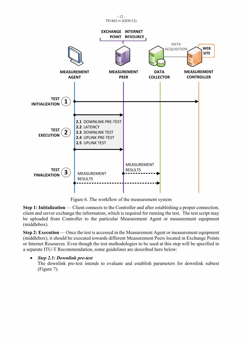
11. Workflow
The workflow of the measurement system is shown on figure 6.
Telecom Operator
(fixed / mobile)
Internet
Network Internet speed test path
External Interface of EP
End-to-end testing
MA MP
LEGEND MA – Measurement Agent MP – Measurement Peer EP – Exchange Point IR – Internet Resource
Telecom Operator
(fixed / mobile) Internet
Internet resource speed test path
EP
End-to-end testing MA
MP
IR
Close location
LEGEND MA – Measurement Agent MP – Measurement Peer EP – Exchange Point IR – Internet Resource
- 12 -
TD 862 r1 (GEN/12)
2.12.22.32.42.5
WEBSITE
DATAACQUISITION
MEASUREMENTCONTROLLER
DATACOLLECTOR
MEASUREMENTPEER
MEASUREMENTAGENT
TESTINITIALIZATION
TESTEXECUTION
TESTFINALIZATION
1
2
3
EXCHANGEPOINT
INTERNETRESOURCE
DOWNLINK PRE-TESTLATENCYDOWNLINK TESTUPLINK PRE-TESTUPLINK TEST
MEASUREMENTRESULTS
MEASUREMENTRESULTS
Figure 6. The workflow of the measurement system
Step 1: Initialization — Client connects to the Controller and after establishing a proper connection,
client and server exchange the information, which is required for running the test. The test script may
be uploaded from Controller to the particular Measurement Agent or measurement equipment
(middlebox).
Step 2: Execution — Once the test is accessed in the Measurement Agent or measurement equipment
(middlebox), it should be executed towards different Measurement Peers located in Exchange Points
or Internet Resources. Even though the test methodologies to be used at this step will be specified in
a separate ITU-T Recommendation, some guidelines are described here below:
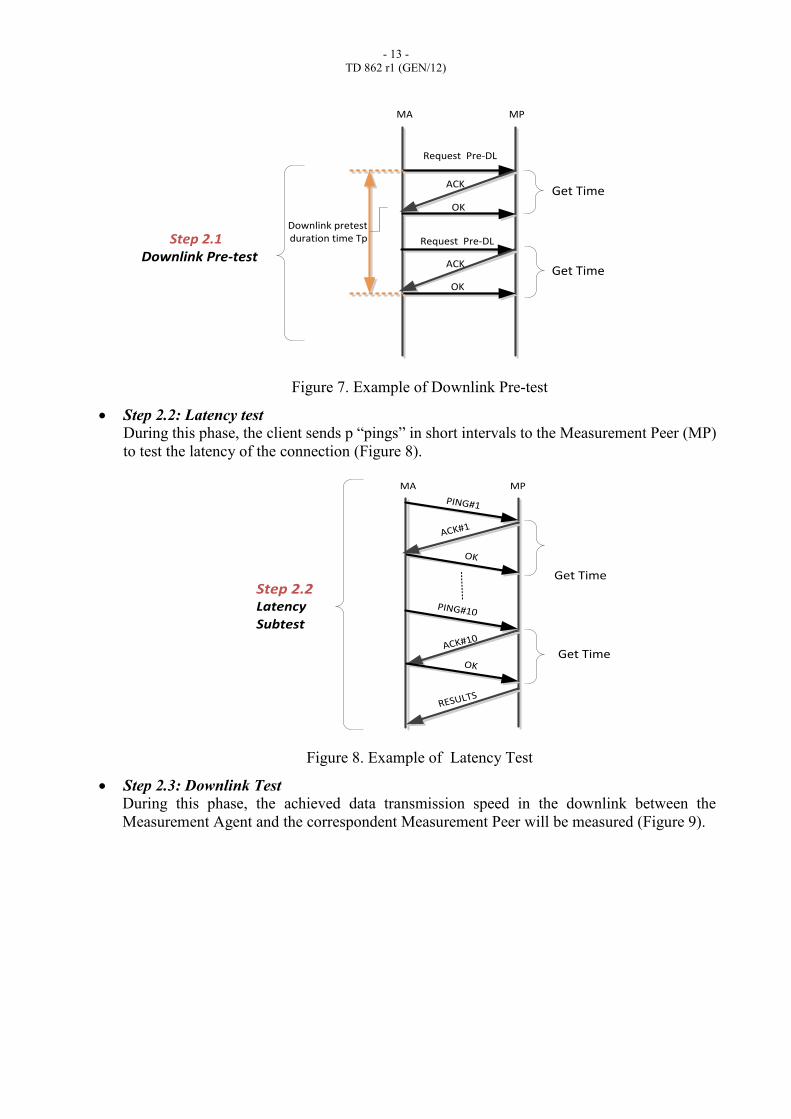
Step 2.1: Downlink pre-test
The downlink pre-test intends to evaluate and establish parameters for downlink subtest
(Figure 7).
- 13 -
TD 862 r1 (GEN/12)
Downlink pretest duration time Tp
ACK
Request Pre-DL
MA MP
OK
OK
Get Time
Get Time
Step 2.1Downlink Pre-test
Request Pre-DL
ACK
Figure 7. Example of Downlink Pre-test
Step 2.2: Latency test During this phase, the client sends p “pings” in short intervals to the Measurement Peer (MP)
to test the latency of the connection (Figure 8).
Step 2.2Latency
Subtest
ACK#1
PING#1
MA MP
RESULTS
OK
Get Time
ACK#10
OKGet Time
PING#10
Figure 8. Example of Latency Test
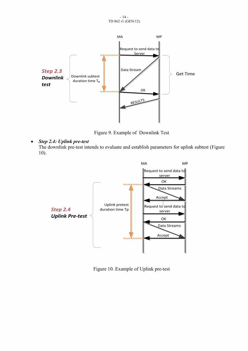
Step 2.3: Downlink Test
During this phase, the achieved data transmission speed in the downlink between the
Measurement Agent and the correspondent Measurement Peer will be measured (Figure 9).
- 14 -
TD 862 r1 (GEN/12)
Downlink subtest duration time Td
Data Stream
MA MP
OK
Get Time
Request to send data to Server
RESULTS
Step 2.3Downlink
test
Figure 9. Example of Downlink Test
Step 2.4: Uplink pre-test
The downlink pre-test intends to evaluate and establish parameters for uplink subtest (Figure
10).
Uplink pretest duration time Tp
Data Streams
Request to send data to server
MA MP
OK
Data Streams
OK
Request to send data to server
Accept
Accept
Step 2.4Uplink Pre-test
Figure 10. Example of Uplink pre-test
- 15 -
TD 862 r1 (GEN/12)
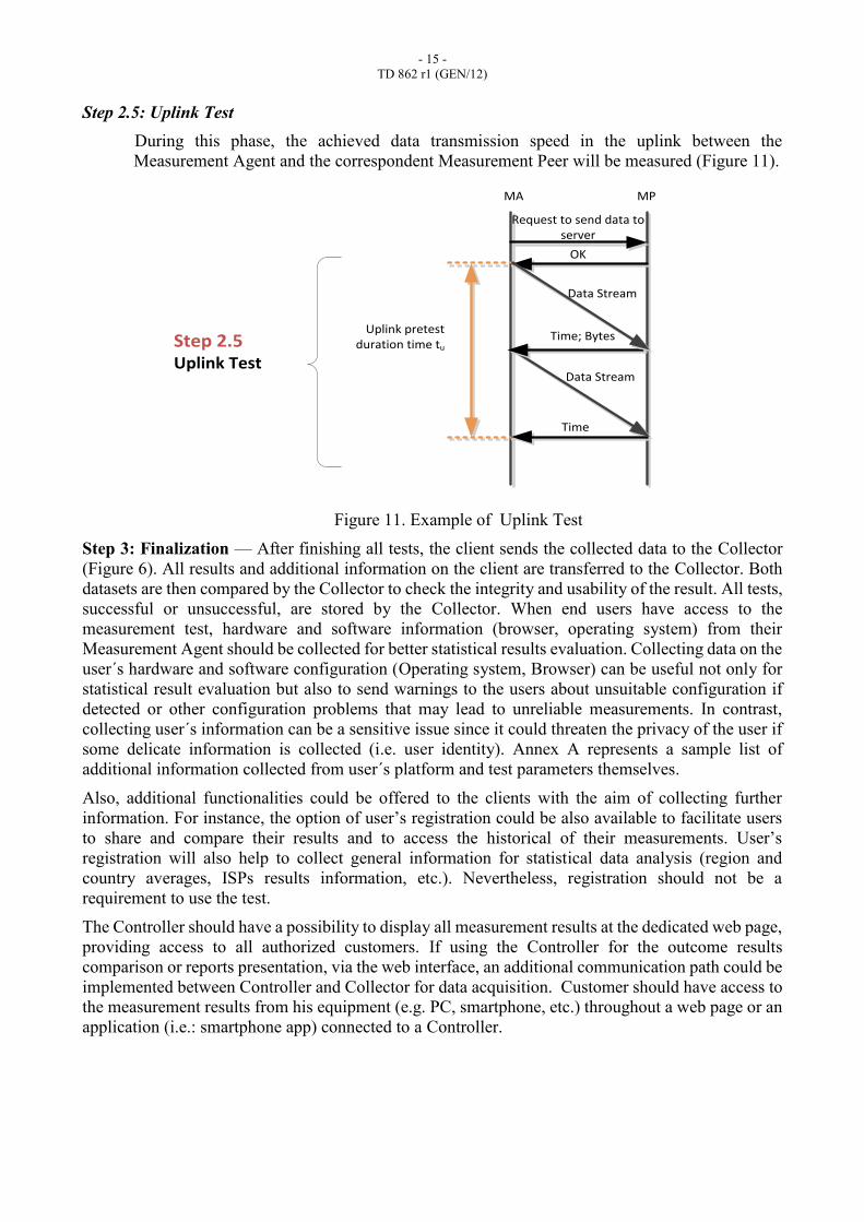
Step 2.5: Uplink Test
During this phase, the achieved data transmission speed in the uplink between the
Measurement Agent and the correspondent Measurement Peer will be measured (Figure 11).
Uplink pretest duration time tu
Data Stream
MA MP
OK
Data Stream
Time; Bytes
Time
Request to send data to server
Step 2.5Uplink Test
Figure 11. Example of Uplink Test
Step 3: Finalization — After finishing all tests, the client sends the collected data to the Collector
(Figure 6). All results and additional information on the client are transferred to the Collector. Both
datasets are then compared by the Collector to check the integrity and usability of the result. All tests,
successful or unsuccessful, are stored by the Collector. When end users have access to the
measurement test, hardware and software information (browser, operating system) from their
Measurement Agent should be collected for better statistical results evaluation. Collecting data on the
user´s hardware and software configuration (Operating system, Browser) can be useful not only for
statistical result evaluation but also to send warnings to the users about unsuitable configuration if
detected or other configuration problems that may lead to unreliable measurements. In contrast,
collecting user´s information can be a sensitive issue since it could threaten the privacy of the user if
some delicate information is collected (i.e. user identity). Annex A represents a sample list of
additional information collected from user´s platform and test parameters themselves.
Also, additional functionalities could be offered to the clients with the aim of collecting further
information. For instance, the option of user’s registration could be also available to facilitate users
to share and compare their results and to access the historical of their measurements. User’s
registration will also help to collect general information for statistical data analysis (region and
country averages, ISPs results information, etc.). Nevertheless, registration should not be a
requirement to use the test.
The Controller should have a possibility to display all measurement results at the dedicated web page,
providing access to all authorized customers. If using the Controller for the outcome results
comparison or reports presentation, via the web interface, an additional communication path could be
implemented between Controller and Collector for data acquisition. Customer should have access to
the measurement results from his equipment (e.g. PC, smartphone, etc.) throughout a web page or an
application (i.e.: smartphone app) connected to a Controller.
- 16 -
TD 862 r1 (GEN/12)
12. Test parameters
At least the following parameters should be measured from/to the specific Measurement Peers by the
proposed methodology (for both the Network Internet speed test and the Internet resource speed test):
Download data transmission speed
The data transmission speed achieved in the downlink between the Measurement Agent and the
correspondent Measurement Peer.
Upload data transmission speed
The data transmission speed achieved in the uplink between the Measurement Agent and the
correspondent Measurement Peer.
Two-way delay
Also defined as the Round-Trip Time (RTT) delay, the two-way delay is twice “the time required
for a packet to traverse the network or a segment of the network” (ITU-T Rec. G.1050).[ACM30]
Note: the test parameters and specific metrics will be specified in a separate ITU-T Recommendation.
- 17 -
TD 862 r1 (GEN/12)
Annex A
List of additional information collecting from user´s hardware and software
The following information may be collected (not limited):
1. Information collected from user´s platform
1.1 For fixed networks
User IP address;
Operating system version;
Web-browser version/User Agent (In case web technology is used);
Note: according to https://www.netztest.at/en/ and section 12.1 of this Recommendation
1.2 For mobile networks (in addition to information for fixed networks):
SIM's network operator ID and name
SIM's network country code and name
Phone type (GSM, CDMA).
Note: according to http://www.fcc.gov/measuring-broadband-america/mobile/technical-summary
2. Test parameters information
2.1 For fixed networks:
Test time;
Time zone;
TCP and UDP settings;
Number of parallel connections (downlink and uplink);
Duration of pre-test;
Duration of the downlink subtest;
Duration of the uplink subtest;
Timeout value;
Number of ‘pings’ during delay subtest;
Maximum elapsed time between ping starts;
Reference size of data block (chunk size);
Number of received chunks after which the MP answers back to the MA
WS advertised during the TCP negotiation phase for the different TCP streams:
Regarding the warnings, although n parallel connections will be launched in the
test, the server will calculate whether for the estimated RTT, OS (TCP flavour +
typical Tx/Rx buffer sizes) and measured WS the calculated downlink and uplink
speeds are too close (>90%) of the theoretical limitations, notifying the user
about the unreliability of the test and the need to optimize his configuration for
achieving better speeds.
2.2 For mobile networks (in addition to information for fixed networks):
Location inferred from cell tower triangulation, WiFi triangulation, or GPS;
Active cell tower ID and signal strength (RSSI);
Visible neighboring cell towers, including cell IDs and RSSI;
Active network operator ID ("MNC") and name;
Active network country code ("MCC") and name;
Bearer (CDMA, GPRS, EDGE, all of the 3G variants, LTE, etc);
____________

![ITU-T Y - IETF · [ITU-T H.248.1] Recommendation ITU-T H.248.1, Gateway control protocol: Version 3. [ITU-T H.460.4] Recommendation ITU-T H.460.4, Call priority designation and country/international](https://img.pdfslide.us/doc/110x75/5f1ddf16a7faaa7d93495e0f/itu-t-y-ietf-itu-t-h2481-recommendation-itu-t-h2481-gateway-control-protocol.jpg)