Embed Size (px)
Citation preview

CONCRETE LIBARY OF JSCE NO. 31, JUNE 1998 RECOMMENDATION FOR DESIGN AND CONSTFIUCTION OF CONCFIETE STRUCTURES
USING CONTINUOUS FIBER REINFOFICING MATERIALS (CONSTRUCTION)
QUALITY SPECIFTCAT IONS FOR CONTINUOUS FIBER REINFORCING MATERIALS (JSCE-E 131-1995)
TEST METHODS FOR CONTINUOUS FIBER REINFORCING MATERIALS
(Translation from the CONCRETE LIBRARY No.88 published by JSCE, September 1996)
JSCE Research Subcommittee on Continuous Fiber Reinforcing Materials
Atsuhiko Machida, Chairman Taketo Uomoto, Secretary
Committee members Chairman Atsuhiko Machida Secretary Taketo Uomoto Members Taisuke Akimoto Tadayoshi lshibashi Takashi Idemitsu
Tamon Ueda Hidetaka Umehara Nobuaki Ohtsuki Kazumasa Ozawa Yoshio Kakauta Hirotaka Kawano Masayuki Kanda Ryoichi Sato Hiroshi Shima Hiroshi Seki Yukikazu Tsuji Seiichi Tottori Makoto Nakasu Junichiro Niwa Atsushi Hattori Tadakatsu Hara Tetsuo Harada Isamu Higai Tsutomu Fukute Mitsuyasu Mashima Kyuichi Maruyama Takehiko Maruyama Ayaho Miyamoto Hiroshi Mutsuyoshi Keitetsu Rokugo Hajime Wakui Yoshifumi Maeda
Committee members from trustees Hikaru Akiyama Yoshiaki Imai Shinichiro Kumagai Seijiro Koga Kenzo Sekijima Hiromitsu aniguchi Tamio Tamura

The Second Research Committee on Continuous Fiber Reinforcing Materials (CFRM) was set up by JSCE Concrete Committee to prepare a set of guidelines for practical design and construction methods together with the standard test methods and specifications of CFRM. The work done by the committee was published in Japanese in Concrete Library, No.88, in 1996. The article includes recommendations for design and construction, specifications, standard test methods and necessary data for using CFRM. Design part of recommendations "Recommendation for Design and Construction of Concrete Structures using Continuous Fiber Reinforcing Materials (Design)" was published in last volume No.30, December 1997. The rest part of the above-mentioned report is published in this volume. KEYWORDS: concrete structures, continuous fiber reinforcing materials, design code,
construction, specifications, standard test methods ----------------------------------------------------------------------------------------------------------------------------------- Atsuhiko Machida is a Professor in the Department of Civil and Environmental Engineering at Saitama University, Urawa, Japan. He received his D. Eng. from the University of Tokyo in 1976. His research interests include application of FRP to concrete structures, steel-concrete hybrid structures, behavior of RC structures under earthquake loading, and behavior of fresh concrete. He is a member of JSCE. ----------------------------------------------------------------------------------------------------------------------------------- Taketo Uomoto is a professor in the Institute of Industrial Science at the University of Tokyo, Japan. He obtained his D. Eng. from the University of Tokyo in 1981. He specializes in composite materials for construction, such as fiber reinforced-plastics, the durability of concrete, and the application of non-destructive testing methods to concrete structures. He holds membership of the JSCE, JCI, ACI and JSNDI. -----------------------------------------------------------------------------------------------------------------------------------

Preface
The Concrete Committee of the Japan Society of Civil Engineers set up a "Research committee on Continuous Fiber Reinforcing Materials (CFRM)" in 1989, chaired by Prof. H.Okamura. The fee for the research works was offered by the Association of Composite materials using Continuous fiber for Concrete reinforcement (CCC). The research committee's work involved various aspects of CFRM, e.g. review of research works and actual applications; study on how to design structures, to deal with durability problems and on the test methods. The committee work was compiled as a state -of-the art report on "Application of Continuous Fiber Reinforcing Materials to Concrete Structures" and published in Japanese in the journal, Concrete Library, No. 72 in 1992.
Another aim of the committee was to offer a chance to committee members to study about the material by their own way in order to collect ideas on the fundamental designing methods. The work done by the committee members was published together with the research work done by other researchers in the proceedings of the Symposium on Application of CFRM on Concrete Structures (Concrete Engineering Series 1) in April 1992. A part of the work related to the designing method and the state-of-the-art report was translated into English and published as "State-of-the-Art Report on Continuous Fiber Reinforcing Materials" (Concrete Engineering Series 3) in October 1993.
For CFRM to be widely used in the field of concrete, it is necessary to have a set of guidelines for practical design and construction methods together with the standard test methods and specifications. The Second Research Committee on CFRM was thus set up by JSCE Concrete Committee, entrusted by CCC and the Advanced Composite Cable Club (ACC), to prepare such guidelines. The committee spent three years from November 1993 to October 1995 to come up with its recommendations. The following four working groups were set up within the committee:
(1) Design method (Chairman: Prof. Y. Kakuta) (2) Construction methods (Chairman: Prof. T. Tsuji) (3) Specifications (Chairman: Prof. T. Uomoto) (4) Standard test methods (Chairman: Prof. H. Seki).
The work done by the committee was published in Japanese in Concrete Library, No. 88, in 1996. The article includes recommendations for design and construction, specifications, standard test methods and necessary data for using CFRM.
This "Recommendation for Design and Construction of Concrete Structures using Continuous Fiber Reinforcing Materials" (Concrete Engineering Series 23) is a translated version of the above-mentioned report which was written in Japanese. I hope that people throughout the world who use CFRM as reinforcement for concrete structures will find the information contained in this book useful. September 1, 1997 Atsuhiko Machida Chairman The Second Research Committee on CFRM, JSCE

RICOMMENDATION FOR DESIGN AND CONSTRUCTION (CONSTRUCTlON)
CONTENTS CHAPTER 1: GENERAL 1.1 SCOPE..........................................................................................................................................60 1.2 DEFINITIONS ..............................................................................................................................60 CHAPTER 2: MATERIALS 2.1 GENERAL....................................................................................................................................63 2.2 CONCRETE..................................................................................................................................63 2.3 CONTINUOUS FIBER REINFORCING MATERIALS...................................................................63 2.4 REINFORCING METERIALS.......................................................................................................64 2.5 PRESTRESSNG STEEL................................................................................................................65 2.6 ANCHORAGES AND COUPLERS................................................................................................65 2.7 SHEATHS.....................................................................................................................................66 2.8 TENDON COATNG MATERIALS AND TENDON PROTECTION MATERIALS...........................66 2.9 GROUT FOR PRESTRESSED CONCRETE...................................................................................67 CHAPTER 3: CONSTRUCTION 3.1 GENERRAL..................................................................................................................................69 3.2 HANDLING AND STORAGE OF MATERIALS ............................................................................69 3.3 PREPARATION, ASSEMBLY, AND PLACEMENT OF CFRM TENDONS, CFRM RENFORCEMENT ETC.....................................................................................................................70 3.3.1 Preparation and assembly of CFRM tendons ............................................................................70 3 3.2 Preparation and assembly of CFRM reinforcement................................................................... ..71 3.3 3 Duct manufacture ....................................................................................................................71 3.3.4 Placement of sheaths and CFRM tendons ..................................................................................72 3.3.5 Assembly and placement of anchorages and couplers. ................................................................73 3.4 CONCRETING..............................................................................................................................73 3.5 PRESTRESSNG............................................................................................................................74 3.6 GROUTNG...................................................................................................................................75 CHAPTER 4: QUALITY CONTROL AND INSPECTION 4.1 GENERAL....................................................................................................................................76 4.2 TESTS...........................................................................................................................................76 4.2.1 General...................................................................................................................................76 4.2.2 Tests for Concrete ....................................................................................................................76 4.2.3 Tests for CFRM tendons ...........................................................................................................76 4.2.4 Tests for anchorages and couplers .............................................................................................78 4.2.5 Tests for other materials used in continuous fiber prestressed concrete.........................................78 4.2.6 Tests for CFRM reinforcement..................................................................................................79 4.2.7 Testing for other materials for use with continuous fiber reinforced concrete................................79 4.3 NSPECTION OF STRUCTURES...................................................................................................80 4.4 CONSTRUCTION RECORDS.......................................................................................................80

CHAPTEF 1: GENERAL 1,1 SCOPE (1) This Recommendation (Construction) provides the general requirements relating specifically to the construction of concrete structures using Continuous Fiber Reinforcing Materials, hereafter called CFRM. The requirements given in this Recommendation are based on JSCE Standard Specification for Design and Construction of Concrete Structures (Construction), hereafter called JSCE Standard Specification (Construction). (2) CFRM used in construction shall normally be materials meeting the requirements given in JSCE-E 131 "Quality Standards for Continuous Fiber Reinforcing Materials". [COMMENT]: CFRM may be used as tendons or as reinforcement in concrete, either singly or in conjunction with prestressing or reinforcing steel. This Recommendation (Construction) gives general requirements relating to the use of CFRM in concrete structures not specified in JSCE Standard Specification (1996). A wide range of CFRM' of varying types and quality are available, but for the purposes of this Recommendation, CFRM used shall normally meet the requirement given in JSCE-E 131. 1.2 DEFINITIONS The following terms are defined for general use in this Recommendation (Construction). Reinforcement: Materials used to reinforce concrete. These include steel and continuous fiber reinforcing materials (" CFRM"). Continuous fiber: General term for continuous fibers used for concrete reinforcement. These include carbon fibers, aramid fibers, and glass fibers, etc. Fiber binding materials: Binders are used to solidify continuous fibers together. These are generally plastic materials such as epoxy resin or vinylester resin. Volume ratio of axial fiber: Ratio of the volume of the actual fiber and the volume of fiber arranged in the direction of strengthening of CFRM. Continuous fiber reinforcing materials (CFM): General term for dimensionally strengthened material for the purpose of reinforcing concrete on being formed by impregnating and hardening continuous fiber with fiber binding material, or only continuous fibers bundled or woven together. CFRM tendons: CFRM used as prestressing materials to induce prestress in concrete mostly used in bar or strand forms. CFRM reinforcement: CFRM other than those used as prestressing materials. CFRM bar: CFRM in the form of bar similar to reinforcing or prestressing steel. CFRM shape: CFRM in the form of sectional steel shape. Continuous fiber reinforced concrete: Concrete reinforced with CFRM. Continuous fiber prestressed concrete: Concrete reinforced by inducing prestress with CFRM.

Capacity of CFRM: Maximum load that CFRM can sustain. Strength of CFRM: Value obtained by dividing the capacity of CFRM by the nominal cross-sectional area. Characteristic value of capacity of CFM: Value for the capacity of CFRM which guarantees that the probability of tested capacity being below this value is within the specified limit based on statistical interpretation of test results. Specified value of capacity of CFRM: Value for the capacity of CFRM which is specified by other design codes or specifications, apart from the characteristic value of capacity of CFRM. Guaranteed capacity of CFRM: Guaranteed capacity according to JSCE-E 131 “Quality Standards for Continuous Fiber Reinforcing Materials”. Design capacity of CFRM: Value obtained by dividing the characteristic value of capacity of CFRM by the material factor. Characteristic value of ultimate strain of CFM: Strain corresponding to the characteristic value of tensile capacity of CFRM. Design ultimate strain of CFRM: Value obtained by dividing the characteristic value of ultimate strain of CFRM by the material coefficient. Tensile rigidity of CFRM: Slope of the tensile force-strain curve for CFRM, when this curve is assumed to be linear. Young's modulus of CFRM: Value obtained by dividing the tensile rigidity of CFRM by the nominal cross-sectional area. Nominal cross-sectional area of CFRM: Value obtained by dividing the volume of CFRM by the length. Bent section of CFRM: Section of CFRM set in a curved shaped by hardening with fiber binding material while continuous fibers are bent. May be in spiral form, stirrup form etc. Curved placement of CFRM: Placement of straight CFRM in a curved layout. Creep failure: Failure due to progressive loss of tensile capacity over time, when CFRM is subjected to a continuous static tensile load. Creep failure capacity: Lead-bearing capacity at time of creep failure. Flexural compressive failure: Form of failure in members subjected to flexure, whereby the compressed section of concrete fails before CFRM for main reinforcement break. Fiber breaking flexural failure: Form of failure in members subjected to flexure, whereby CFRM for main reinforcement break before failure of the compressed section of concrete. Fiber breaking shear failure: Form of shear failure in members subject to shear forces, whereby CFRM for shear reinforcement break. Tendon coating materials: Coating materials applied to tendons to prevent bonding with concrete. Tendon protection materials: Materials used to protect tendons from physicochemical deterioration due to external forces.

[COMMENT]: Definitions of shear reinforcement, hoop ties, spiral hoops, and tendons follow those given in JSCE Standard Specification (Design), where "steel" shall be taken to signify HCFRM". The nominal cross-sectional area of CFRM is obtained by dividing the volume of CFRM by the length. As volume generally includes elements not contributing to the strength of the reinforcement, the strength and Young's modulus of CFRM, obtained using the nominal sectional area, are generally not equal to those of the continuous fiber itself.

CHAPTER 2: MATERIALS 2.1 GENERAL Material; to be used shall be of confirmed quality. [COMMENT]: CFRM are new materials with limited field experience, and for some types little data on quality are available. It is therefore necessary to confirm the quality of the materials. In order to enhance the effectiveness in service of CFRM, it is particularly important to ensure that the concrete and any reinforcing or prestressing bars, anchoring devices, couplers, covering, protective materials, sheaths, grout etc. are of confirmed quality. 2.2 CONCRETE (1) Concrete shall have a design strength of not less than the values given in table 2.2.1.
Table 2.2.1 Minimum design strength of concrete CFRM application Minimum design strength As substitute for reinforcing bars As prestressing materials
21 N/mm2
30 N/mm2 (2) Concrete quality shall be in accordance with chapter 2 of JSCE Standard Specification (Construction). (3) Quality of cement, water, fine aggregate, coarse aggregate, and admixtures used in concrete shall be in accordance with chapter 3 of JSCE Standard Specification (Construction). [COMMENT]: When using CFRM as prestressing materials, greater compressive strength of concrete is required, as with conventional prestressed concrete structures. In structures where steel is not used and where there is no danger of corrosion of CFRM anchorages and couplers, the limitations on chloride contents in concrete given in JSCE Standard Specification (Construction) need not be applied. An excess of alkali ions such as Na+ and K+, however, will tend to accelerate alkali-aggregate reaction, and appropriate methods should be taken to prevent alkali-aggregate reaction, for instance by eliminating reactive aggregate. 2.3 CONTMUOUS FIBEFI RELNFOF3CING MATERLALS (1) CFRM used in construction shall normally be materials meeting the requirements given in JSCE-E 131 ''Quality Standards for Continuous Fiber Reinforcing Materials”. (2) Where CFRM do not meet the requirements of JSCE-E 131 "Quality Standards for Continuous Fiber Reinforcing Materials'' are to be used, tests must first be carried out to establish the design strength, design value of modulus of elasticity, design ultimate strain and method of use. (3) Where CFRM are to be subjected to heat treatment or other form of processing for anchoring, jointing, processing, assembly or placement, tests shall be performed to determine the level of quality loss due to the treatment, and an appropriate deign tensile strength and other design values shall be determined separately. [COMMENTS]: (2) Tests shall be conducted according to JSCE-E 531 “Test Method for Tensile Properties of Continuous Fiber Reinforcing Materials”, and guaranteed values such as the tensile strength, modulus of elasticity and

ultimate strain shall be determined based on the test results. Bonding strength shall be tested according to JSCE-E 539 “Test Method for Bond Strength of Continuous Fiber Reinforcing Materials by Pull-Out Testing”. Flexural tensile failure strength, creep failure strength, relaxation, fatigue strength, coefficient of thermal expansion, alkali resistance, and shear strength shall be determined using test methods meeting JSCE standards. Values determined using well-established alternative test methods, however, may also be used provided a reliable guaranteed value allowing for the effect of anchorage is obtained. (3) See section 3.3 below for details of treatment and handling for heat treatment or other forms of processing. 2.4 REINFORCING BARS (1) Where CFRM are to be used in conjunction with reinforcing bars, the bars shall be selected to conform to the intended purpose of the CFRM. (2) Where CFRM are to be used to enhance the corrosion resistance of a structure, epoxy-coated reinforcing bars used in conjunction with the CFRM shall conform to JSCE-E 102 "Quality Standards for Epoxy-Coated Reinforcing Steel Bars''. (3) Where ordinary reinforcing bars without corrosion-proofing are to be used, section 3.7.1 of JSCE Standard Specification (Construction) shall be adhered to. [COMMENTS]: (1) CFRM are used mainly for their corrosion-resistant and non-magnetic properties, therefore reinforcing bars used in conjunction with CFRM must be selected in accordance with the intended purpose. It should be noted in this connection that non-magnetic reinforcing bars have also been developed in recent years. (2) The material properties of CFRM tend to lead to their being used in harsh, saline environments etc., thus epoxy-coated reinforcing bars are prescribed as standard for use in conjunction with CFRM, in order to ensure corrosion protection. Galvanized reinforcing bars could also be considered, but owing to the lack of experience with this in combination with CFRM, epoxy-coated reinforcing bars have been preferred here. (3) Where ordinary unprotected reinforcing bars are used, the prescription given in section 3.7.1 of JSCE Standard Specification (Construction) of conformity with JIS G 3112 “Steel Bars for Concrete Reinforcement" must be adhered to. Stainless and corrosion-proof reinforcing bars have been developed in recent years. Where these or non-magnetic reinforcing bars re to be used, they must first be confirmed to have performance equivalent to the JIS standard quoted above. 2.5 PRESTRESSING STEEL Where prestressing steel is to be used, section 3.7.2 of JSCE Standard Specification (Construction) shall be adhered to. [COMMENT]: Where ordinary prestressing steel without corrosion-proofing is to be used, the requirements of section 3.7.2 of JSCE Standard Specification (Construction) are to be applied as-is; this means prestressing steel must generally conform to JIS G 3109 “Steel Bars for Prestressed Concrete", JIS G 3137 "Small size Deformed Steel Bars for Prestressed Concrete”, and JIS G 3536 "Uncoated Stress-relieved Steel Wires and Strands for Prestressed Concrete''. Corrosion-proofed or stainless prestressing steels have been developed in recent years. Where these steels are to be used, they must first be confirmed to have performance equivalent to the JIS standards quoted above, and, additionally, the effectiveness of their corrosion-proofing must be adequately assessed.

2.6 ANCHORAGES AND COUPLERS (1) Anchorages and couplers shall be of a structure and strength such that they do not fail below the guaranteed capacity or undergo significant deformation. (2) Materials used in anchorages and couplers shall be of confirmed quality. (3) Anchorages and couplers shall be tested for performance according to JCSE-E 537 “Test Method for. Performance of Anchorages and Couplers in Prestressed Concrete using Continuous Fiber Reinforcing Materials". [COMMENTS]: (1) Anchorages or couplers shall be of a structure and strength corresponding to or superior to the anchoring or coupling system using CFRM, allowing for safety during prestressing work, the need to prevent excessive set in anchorage etc. The guaranteed capacity of the anchorages or couplers, and the guaranteed capacity of the tendons, are treated separately here. The reason for this is that the tensile strength of CFRM is evaluated allowing for the effects of the anchorages, while in many cases the anchoring device does not allow the CFRM to exert its full tensile strength, and in multi-cables especially, the fall-off is significant. “Anchoring or coupling system using CFRM” here refer respectively to systems configured with CFRM and anchorages, and CFRM and couplers. (2) "Materials used in anchorages and couplersr' refers to synthetic resins, anchoring expansion agents, grout, anchor bars etc. As these are the most important materials in anchoring and coupling of prestressed concrete structures, they must be of proven, reliable quality and outstanding durability. (3) Performance testing of anchorages and couplers may be carried out according to JSCE-E 537. This test, however, is intended for new types or types for which adequate test data is not available; testing may be omitted for types of proven quality and reliability. for which test data is given in the Documentation section of this Recommendation. 2.7 SHEATHS (1) Sheaths shall be of a type not easily deformed during handling or concrete placement, and capable of withstanding intrusion of cement paste at laps and joints. (2) Sheaths should be preferably have low friction with tendons, and should not cause damage to tendons during tensioning. (3) The effects of the sheaths on the structure must be fully known. [COMMENTS]: (1) Bonding between CFRM and prestressed concrete grout, or between sheaths and concrete, may or may not be factored into the design, therefore the sheath material and geometry must give the performance intended in the design. Plastic sheaths may be used, in addition to conventional steel sheaths. Plastic sheaths must be sufficiently rigid to prevent any hindrance of placement etc. Severe deformation of sheaths or leakage of cement paste may hinder or prevent prestressing work, therefore the use of non-rigid or damaged sheaths must be avoided. (3) The bonding characteristics of the intended sheaths with concrete and grout, and the effects on the structure of cracking, differences in coefficients of thermal expansion etc. must be fully known in advance. Details of handling of sheaths are given in section 3.3.4 below.

2.8 TENDON COATING MATERIALS AND TENDON PROTECTION MATERIALS (1) Materials used for tendon coating shall not cause damage to CFRM tendons or to the concrete, and shall not cause bonding between CFRM tendons and the concrete during prestressing. (2) Tendon protection materials shall protect CFRM tendons fully from damage due to external factors. [COMMENT]: Tendon coating materials ire used to prevent bonding between CFRM tendons and concrete, whereas tendon protection materials are used to protect CFRM tendons from physicochemical deterioration due to external factors, hence the distinction drawn here between the two types of material. Both types should of course fulfill their intended purpose, and the materials used must be of guaranteed durability and quality. 2.9 GROUT FOR PRESTRESSED CONCRETE (1) Grout for prestressed concrete shall be of sufficient quality to protect the tendons and to form a monolithic structure by bonding with the member concrete and the tendons. (2) The quality and materials of cement grout for prestressed concrete shall satisfy the following conditions. (a) Consistency: The consistency shall be set at a level appropriate for the construction, taking into account the length and shape of the sheaths and ducts, construction season and weather conditions, type of tendon and the proportion of the sectional area of the prestressing steel to that of the duct. (b) Bleeding rate: The bleeding rate shall be not more than 3%, and preferably not more than 1%. (c) Expansion rate: The expansion rate shall be not more than 10%. The expansion rate after grouting shall exceed the bleeding rate until maximum bleeding is reached. The standard time from the completion of agitation to the completion of grouting should be around 30 minutes. (d) Strength: Compressive strength at 28 days shall be not less than 20 N/mm2. (e) Water-cement ratio: The water-cement ratio of the grout shall be not more than 45%. (i) Cement: Cement used for grouting shall comply with JIS R 5210. (g) Water: Water used for grouting shall not contain harmful levels of substances adversely affecting the grout or the prestressing tendons. (h) Admixtures: The advisability of using admixtures, and the quality and method of use of the admixtures, shall be studied in advance. (3) Grout for prestressed concrete other than that specified in (2) above shall first be checked for quality and the method of use adequately studied. [COMMENTS]: (1) The purpose of grouting is to protect the tendons and to create a monolit hic structure through bonding of member concrete and tendons. The grout must therefore fill ducts completely, and surround the tendons. The grout must therefore maintain good fluidity and workability up to the completion of grouting, with minimum bleeding, proper expansion after grouting, and adequate strength Grouting should ideally be carried out from below, causing the grout to flow gradually upwards. Where tendons are placed with multiple bend-ups and bend-downs, grout will shift from higher levels to lower levels, therefore the use of high quality grout with little or no bleeding is advised. Further, if the gap between sheaths and tendons is too narrow, it will not be properly grouted, therefore the use of large-diameter sheaths and high quality grout is advised. (2) High-quality grouts are now available with superplasticizers in place of conventional plasticizers, giving little or no bleeding, and maintaining initial levels of fluidity for long periods while at the same time giving high viscosity.

The water-cement ratio should be kept as low as possible given the fluidity requirements. A high water-cement ratio will cause loss of strength and bonding, and incomblete grouting of ducts due to bleeding and shrinkage. Conversely, a low water-cement ratio will result in high viscosity and poor workability. The standard water-cement ratio is therefore given as 45%. The use of recently developed superplasticizers allows the water-cement ratio to be reduced while giving a grout with high fluidity and workability. (3) The use of cement-based grout may be inadvisable in certain circumstances owing to adverse effects on durability of CFRM tendons. In such cases, tests should be carried to check that the grout meets the required quality standards.

CHAPTER 3: CONSTRUCTION 3.1 GENERAL (1) Handling and storage of materials, assembly and placement of CFRM and steel, placement of concrete, prestressing and grouting of prestressed concrete shall be carried out in the order given in the construction plan, and following the prescribed procedures. (2) For the construction of concrete structures, engineers having sufficient knowledge of concrete construction shall be present on site. [COMMENT]: (2) "Engineers having sufficient knowledge of concrete construction'' (concrete specialists) shall be construed as Concrete engineers or Chief Concrete Engineers authorized by the Japan Concrete Institute, Prestressed Concrete Engineers authorized by the Prestressed Concrete Technology Association, or other engineers with similar or superior specialist skills. The presence of such engineers on site to supervise construction appropriately is extremely important in obtaining the desired quality of concrete. For particularly important structures, it is recommended that such engineers be stationed permanently on site. 3.2 HANDLING AND STORAGE OF MATERIALS (1) CFRM shall be handled carefully to prevent any damage to the surface. (2) When storing CFRM outdoors, placing them directly on the ground should be avoided, and a suitable cover shall be provided. CFRM should also not be placed directly on the ground when stored in storehouses, and if necessary suitable covers should be provided. Environmental factors such as high temperature, ultraviolet rays, chemical substances etc. deleterious to CFRM should be eliminated, and the CFRM shall be stored in such a manner as to prevent damage or deformation. (3) Anchorages, couplers and materials used in anchorages and couplers shall be stored in a storehouse, free from dust and protected from damage, deformation or deterioration. [COMMENTS]: (1) CFRM are generally made with a matrix of synthetic resin, rendering them liable to surface damage. Deep scoring by sharp steel edges etc. will significantly reduce their failure load, possibly resulting in serious accidents especially when the CFRM are used as tendons. Scoring of the surface of glass fiber based CFRM may cause loss of durability due to infiltration of alkalis through the damaged areas, therefore care is advised in the handling of these materials also. (2) Storage of CFRM directly on earth or concrete, whether outdoors or in a storehouse etc., increases the likelihood of damage or loss of quality, and such locations should be avoided. High temperatures, ultraviolet rays, chemical substances etc. are also deleterious to CFRM, and these factors too should be eliminated. CFRM must be stored in an environment free from possible sources of damage. CFRM shipped in coil form should be stored in such a way that harmful kinks etc. do not develop when the coil is unwound. (3) Anchorages, couplers and materials used in anchorages and couplers are important elements in prestressed concrete, therefore storage in a storehouse is prescribed. Parts destined to be in contact with concrete or grout must also be kept free from-grease, dirt, dust etc. to ensure full bond strength.

3.3 PREPARATION, ASSEMBLY AND PLACEMENT OF CFRM TENDONS, CFRM REINFORCEMENT ETC.
3.3.1 Preparation and assembly of CFRM tendons (1) CFRM tendons shall be prepared and assembled in such as way as to give the configuration and dimensions specified in the design, while avoiding any damage to the material. Any CFRM tendons found to be damaged on the surface, bent, subjected to high temperatures or stored out of doors for long periods shall be discarded. (2) CFRM tendons shall in general not be bent. Where bending is unavoidable, this shall be done in a workshop using techniques that do not damage the material. The tensile strength of CFRM tendons after bending shall be confirmed using appropriate testing methods. (3) CFRM tendons used in pretensioning, and CFRM tendons required to bond, shall be cleared of any oil, grease or foreign matter likely to impair bonding prior to assembly. [COMMENTS]: (1) CFRM tendons must be correctly formed into the configuration and dimensions specified in the design, without damaging the material. Cutting of CFRM tendons, preparation for anchoring or fitting of anchorages etc. should be carried out according to the proper method for CFRM tendons. CFRM tendons should be cut using an efficient high-speed rotatory grinder or similar manner which does not damage the material. CFRM tendons which are bent or have surface damage must not be used, as there is a possibility of severe loss of tensile strength. CFRM tendons which have been subjected to high temperatures should also not be used, as the thermal deterioration of the resins causes loss of fiber binding performance, which could result in loss of tensile strength. Depending on the type of CFRM tendons, long exposure to direct sunlight may result in deterioration due to ultraviolet rays, therefore CFRM tendons stored out of doors for long periods should not be used. (2) The fiber binding material in CFRM tendons is generally a thermosetting resin, and bending such a material on site while maintaining the required quality is technically difficult. Therefore, CFRM tendons should generally not be bent. If bending of CFRM tendons is unavoidable, this should be done in a workshop following methods which do not damage the material. As the tensile strength of CFRM tendons is thought to be reduced by bending and according to the bending radius, the tensile strength should be confirmed by appropriate methods reconstructing the actual conditions of use, and checked against the design conditions. (3) Foreign matter such as grease, paint and dirt may impair the bonding between concrete or grout and CFRM tendons, resulting in slippage of tendons. The surface of CFRM tendons must therefore be thoroughly cleaned before use. 3.3.2 Preparation and assembly of CFRM reinforcement (1) CFRM reinforcement shall be prepared and assembled following methods which do not damage the material, so as to conform to the configuration and dimensions given in the design. Any CFRM reinforcement found to be damaged on the surface, bent, subjected to high temperatures or stored out of doors for long periods shall be discarded. (2) Bending of CFRM reinforcement shall normally be done in a workshop, following methods which do not damage the material. (3) Where the bending radius of the CFRM reinforcement is not given in the design, the bending radius and bending method shall be determined on the basis of tests conducted to confirm that the tensile strength required in the design is met.

(4) CFRM reinforcement shall be cleared of any oil, grease or foreign matter likely to impair bonding prior to assembly. [COMMENTS]: (1) CFRM reinforcement must be handled similar to the case of CFRM tendons according to the comment of section 3.3.1(1). (2) For the same reason as that given in the comment of section 3.3.1(2), bending of CFRM reinforcement such as stirrups and spiral reinforcement shall normally be done in a workshop. Certain types of CFRM reinforcement may be bent and thermoset on site, or bent by heating on site using thermoplastic resins, but the tensile strength of CFRM reinforcement bent in this way must still be confirmed by appropriate testing methods. (3) The tensile strength of bent CFRM reinforcement is known to be reduced by the bending process, but the level of strength loss depends on the type of continuous fiber, the manufacturing process of the reinforcement, the bending radius etc. The bending radius and method of bending must therefore be determined based on tests to confirm the extent of loss of tensile capacity, and the bending radius should be made as large as possible. (4) See the comment of section 3.3.1(3). 3.3.3 Duct manufacture The materials and methods used in duct manufacture shall not be injurious to CFRM tendons, reinforcement or concrete. [COMMENT]: Materials used in duct manufacture must be confirmed not to erode CFRM tendons or reinforcement, or to cause deterioration of concrete, prior to use. The manufacturing method must not cause cracking in concrete, significant increase in friction during prestressing, or damage to CFRM tendons. Where subsequent bonding is required, the concrete and CFRM tendons must act as a monolithic body, therefore a high level of bonding between the duct and the concrete or grout. 3.3.4 Placement of sheaths and CFRM tendons (1) Damaged sheaths or sheaths with severe internal rusting shall not be used. Joints of sheaths shall be securely sealed to prevent penetration of cement paste during concreting. (2) Sheaths and CFRM tendons shall be firmly supported at the required positions and in the required directions by methods not injurious to the material, and placed correctly to ensure their position and configuration remain unchanged during concrete placement. The bending radius of bent CFRM tendons shall be determined so as not to impair the tendon. (3) CFRM tendons shall be placed in sheaths without any entanglement. (4) CFRM tendons used in pretensioning shall be protected from damage due to contact with end forms. Unbonded CFRM tendons shall be carefully installed without any damage to the coatings. (5) Sheaths and CFRM tendons shall be inspected after placement, and corrective measures such as repair or replacement shall be taken in the event of damage or dislocation being found. (6) Tolerances for placement positions of CFRM tendons shall be determined within a range not affecting the members, and allowing for factors such as the size of the members.

[COMMENTS]: (1) Steel sheaths with significant internal rusting must not be used. This is not only because of the increased friction during prestressing, but also because of possible damage to CFRM tendons and impairment of bonding. Foreign matter such as grease and loose rust likely to impair bonding shall be removed from the interior of the sheath before use. Incomplete jointing between sheaths, between sheaths and anchorages, or between sheaths and couplers connectors may cause cement paste to leak into the sheath during concreting, leading to bonding impairment similar to that described in relation to damaged sheaths. The joints must be protected from ingression of cement paste by extending the lap, winding with insulating tape etc. It is important to prevent corrosion of sheaths at anchorage ends by application of rust-preventive agents or similar treatment. In order to prevent damage to CFRM tendons within the sheath, plastic sheaths etc. may be used, but their performance must be thoroughly evaluated first. 3,3.5 Assembly and placement of anchorages and couplers (1) Anchorages and couplers shall be assembled accurately in the configuration and dimensions specified in the design documents, and shall be properly installed in the location and direction specified in the design. Anchorages and couplers, and reinforcement in their vicinity, shall be corrosion-proofed if necessary. (2) The bearing surface of the anchorage shall be installed perpendicular to CFRM tendons. Anchoring of CFRM tendons to the anchorages shall be carried out according to the prescribed procedures, and due care shall be taken to prevent any damage to CFRM tendons at the anchorage, or loss of anchoring capacity. (3) When CFRM tendons are coupled, the couplers shall have sufficient capacity and corrosion- proofing, and the pulling side of the coupler shall be allowed adequate movement to apply tension to CFRM tendons. (4) After the placement of the anchorages, an inspection shall be made, and damaged hardware shall be replaced or repaired. Dislocation of the hardware shall also be corrected. [COMMENTS]: (1) and (4): Anchorages are subject to tremendous forces, and their proper assembly and placement following the design drawings is important to ensure proper transfer of stresses and to avoid accidents. With current technology, the use of metal anchorages and couplers is unavoidable, thus proper corrosion-proofing is required to prevent loss of structure durability due to corrosion. (2) If the bearing surfaces of anchorages are not placed perpendicularly to CFRM tendons, local bending of CFRM tendons during tensioning or anchoring may result. This local bending could lead to failure of CFRM tendons, or prevent the completion of anchoring work. The anchorages and tendons must therefore be installed perpendicularly to each other, and a straight portion of a certain length should be allowed in CFRM tendons around the anchorages. As the anchoring methods used with CFRM tendons vary according to the construction technique, the prescriptions for anchoring given for each technique must be followed. The use of inappropriate anchoring methods could prove fatal for prestressed concrete structures, therefore proper technical controls on anchoring work must be enforced. (3) When CFRM tendons are coupled, the couplers must be corrosion-proofed to prevent loss of member durability. The movement of the couplers during tensioning must be calculated and a sufficient space for the movement must be provided on the tensioning side of the couplers. The positions of joints must be checked

after assembly of couplers. 3.4 CONCRETING (1) Batching, mixing, transportation, placing, curing, surface finishing etc. of concrete shall be carried out
according to the prescribed procedures. (2) Casting and compaction of concrete shall be carried out taking due care to avoid disturbing the placement of CFRM, reinforcing bars, anchorages, sheaths etc., avoiding damage to CFRM and ensuring full concreting of all areas around CFRM and reinforcing bars, anchorages, sheaths etc. (3) Steam curing shall be performed following thorough assessment of the temperature characteristics of CFRM, anchorages, couplers etc. used, setting the curing temperature accordingly. [COMMENTS]: The general remarkable points for concreting are given in JSCE Standard Specification (Construction). Batching and mixing are covered in chapter 5 of JSCE Standard Specification (Construction), transportation and placing in chapter 7, curing in chapter 8 and surface finishing in chapter 12. Each of these chapters is followed here. In addition, the smaller member dimensions and higher strength of concrete are used in prestressed concrete structures as compared to normal reinforced concrete structures, therefore particular caution is advised during placement because of the use of different quality concrete from that used in reinforced concrete structures. (2) In prestressed concrete, there is a danger of displacing not only CFRM and reinforcing bars and forms, but also anchorages and sheaths, therefore operations must be carried out with caution. It should be borne in mind that the lower weight and rigidity of CFRM in comparison to reinforcing bars renders it more liable to displacement due to buoyancy. Reinforcing-bar workers should stay during concrete placement work to correct any dislocation of CFRM or reinforcing bars, anchorages, sheaths etc. CFRM may be damaged by direct contact with an internal vibrator, therefore the use of internal vibrators protected with polyurethane etc. is recommended. (3) Certain types of CFRM, anchorages, couplers, sheaths etc. exhibit material quality change under steam curing temperatures, hence this provision is made. Particular care must be taken with regard to the increased relaxation and loss of bond strength in CFRM at high temperatures. When steam curing is used, heating should begin after not less than three hours after concrete placement, and the rate of temperature increase shall generally be not more than 15 Co per hour. The curing temperature ;hall be not more than 65 Co , and the temperature shall be low enough to avoid impairing the quality of CFRM and the anchorages or couplers. 3.5 PRESTRESSING (1) The tensile forces to be applied to CFRM tendons in prestressing, the method of prestressing, safety measures during prestressing, method of calibration of the tensioning apparatus, minimum concrete strength for prestressing, and methods of prestressing control shall be determined according to the prescribed procedures. (2) The coefficient of friction and apparent modulus of elasticity applied in control of prestressing work shall generally be determined based on prestressing tests on site. (3) The coefficients of friction of the tensioning apparatus and the anchorages shall also be determined based on testing. (4) Tendons shall be anchored to ensure that all the constituent CFRM tendons are subjected to the required tensile force.

[COMMENTS]: Prestressing work is covered in section 27.6 of JSCE Standard Specification (Construction), which is also applied here. For the techniques given in the Documentation section of this Recommendation, the control methods given for each technique shall be adhered to. (l) Since the elongation of CFRM tendons is greater for a given prestressing level than the elongation of prestressing steel, use of a jack with a long stroke, use of a succession of different jacks etc. must be considered. (2) Measurements of the coefficient of friction and apparent modulus of elasticity shall be made at the start of work, and redone if any anomalies are found during control of prestressing work. Control of prestressing may be carried out based on the measured coefficient of friction µ . The tolerances for µ given in Table 27.6.1 in the comment to section 27.6.4 of JSCE Standard Specification (Construction) relate to prestressing steel only. For CFRM tendons, tolerances of µ must be calculated in the same way as those for prestressing steel. (4) For CFRM tendons, the stress - strain curve is linear with no yielding, and the ultimate strain is lower than that for prestressing steel. Further, as the strength loss in CFRM tendons due to bending is greater than in steel, tensioning of CFRM tendons and anchoring to the anchorage must be carried out carefully to avoid brittle failure. This will require initial alignment of parts exerting tensile force on each CFRM tendons and monitoring of extension during prestressing to be enforced more strictly than is generally the case for prestressing steel. Prestressing of CFRM tendons must be carried gradually, avoiding sudden increases in tensile force. The amount of slipping when anchoring CFRM tendons can be greater than with prestressing steel, but owing to the lower tensile rigidity' the reduction in tensile force in CFRM tendons due to slipping in the anchorages is generally less. 3.6 GROUTING (1) Where integration of member concrete and CFRM tendons by grouting is required, grouting shall be carried out immediately after the completion of prestressing. (2) Selection of grouting tools, batching, mixing, agitation, injection, requirements for work in hot or cold weather etc. shall be according to the prescribed procedures. [COMMENT]: For cement-based grout, specification (1) is given in the section of 27.7.1 and specifications(2) is given in the section of 27.7.2~27.7.6 of JSCE Standard Specification (Construction) and these specifications should be followed here. For non-cement grouts, suitable working procedures should be applied allowing for the differing characteristics of the materials, based on the above.

CHAPTER 4: QUALITY CONTROL AND INSPECTION 4.1 GENERAL The necessary quality control and inspections of concrete materials, CFRM, steel used in conjunction with CFRM, other materials, equipment, working procedures and completed structures shall be carried out to ensure the safe and economic construction of continuous fiber reinforced concrete structures of the required quality. [COMMENT]: Quality control when using CFRM is equally as important as when conventional materials are used (c.f. the comment of section 13.1 of JSCE Standard Specification (Construction). 4.2 TESTS 4,2.1 General Quality control shall be carried out by testing of materials, equipment and machinery according to the prescribed methods, in order to ascertain their performance. Testing of CFRM shall generally be carried out according to this Recommendation. [COMMENT]: General provisions for quality control methods are given in the comments of section 13.1 and l3.2 of JSCE Standard Specification (Construction), but as JIS standards for testing of CFRM are not available, this Recommendation has been adopted as standard. 4.2.2 Tests for Concrete The performance of concrete before and after work, and if necessary also during work, shall be tested according to the prescribed methods. [COMMENT]: Tests for quality control of concrete are given in section 13.5 and 27.10.1 of JSCE Standard Specification (Construction), and these specifications are followed here. As noted in the comments of section 2.2 above, in structures where CFRM are not used in conjunction with steel and where there is no possibility of corrosion of anchorages and couplers, the requirements for chloride contents in concrete given in JSCE Standard Specification (Construction) need not be applied. Contents of chloride ions in concrete must still be tested and kept within strict limits in order to prevent deterioration of the concrete itself due to alkali-aggregate reaction etc. 4,2.3 Tests for CFRM tendons (1) Quality tests shall be conducted on CFRM tendons prior to use, in order to ensure the required performance. Quality testing shall cover the following items: (a) Tensile strength (or maximum tensile load); tensile modulus of elasticity (or tensile rigidity), and ultimate strain; (b) Fatigue strength; (c) Relaxation rate; (d) Bond strength; (e) Coefficient of thermal expansion; (f)Other
The above tests may be dispensed with for materials of proven quality and performance. (2) Quality of tensioning systems using CFRM tendons shall generally be tested for the whole system including anchorages and couplers, with quality testing carried out before use to ascertain performance. Quality testing shall cover the following items: (a) Tensile strength.(or tensile load); tensile Young's modulus (or tensile rigidity); (b) Fatigue strength; (c) Relaxation rate The above tests may be dispensed with for materials of proven quality and performance. [COMMENTS]: The handling of CFRM is generally very different from that of steel in terms of mechanical properties, durability and handling method, and quality controls must be implemented allowing for these differences. (1) These tests are required to control the performance of CFRM tendons themselves; bond strength testing may be omitted for CFRM tendons to be used unbonded. “Other” tests refers to accelerated deterioration testing in high temperatures, alkaline or acid conditions, creep failure testing etc. Such tests shall be performed if necessary to ascertain quality. Quality control through these tests is extremely important, but it normally requires special, precision testing equipment, extensive expertise in measurement and / or long periods of time. Adoption of manufacturers guaranteed values has therefore been allowed where performance has been checked by suitable testing prior to shipment, and where the suitability of transportation methods has been confirmed. If there is a possibility of mishandling during shipment or of significant damage due to long periods of storage, however, the materials must not be used without first being tested, even in the absence of any visible damage. This shall also apply to materials during work; materials suspected of having suffered damage shall immediately be replaced and tested. Possible factors affecting CFRM before and during work are given below. -Factors affecting CFM before start of work: Bending beyond prescribed limits, subjection to shocks, dragging etc. during transportation; temperature, humidity, dampness or direct sunlight (ultraviolet rays) during storage; welding sparks, chemicals etc. -Factors affecting CFRM during work: Bending or impact force beyond allowed limits during placement; over-tight binding, welding sparks, chemicals, excessively high temperatures during curing etc. (2) The mechanical properties of CFRM tendons are significantly affected by the anchorages and couplers, and there is a tendency for systems as a whole to give lower performance than either single or multiple tendons alone. When using CFRM tendons, therefore, tests must be carried out on factors likely to be affected when anchorages and couplers are used in a complete system, in order to ascertain performance. These tests may be dispensed with for CFRM tendons of proven quality used in conjunction with anchorages and couplers of guaranteed quality and known performance, which are specified in the Documentation section of this Recommendation as being designed expressly for use with CFRM tendons in question. 4.2.4 Tests for anchorages and couplers Anchorages and couplers for use with CFRM tendons shall be tested for quality before use. Such tests may be dispensed with for materials of proven quality. [COMMENT]: The geometry, performance, service conditions etc. of anchorages and couplers vary significantly for different types, and also depending on the type of CFRM tendons they are used with. Such anchorages and

couplers must therefore be tested following an appropriate method capable of reproducing the service conditions and expected tensile forces. Tests must confirm that the strength and structure of the materials are such that failure or significant deformation do not occur below the guaranteed tensile load, and that the required anchoring or coupling effect is achieved with the proposed CFRM tendons. Standard test methods for anchorages and couplers are given in JSCE-E 537 "Test Method for performance of Anchorages and Couplers in Prestressed Concrete using Continuous Fiber Reinforcing Materials", and these test methods may be followed here. Depending on the type of anchorages and couplers, it is also important to check that set loss due to tendon slippage is within allowable limits; furthermore, given that continuous fiber reinforced concrete structures are often located in extreme environments, any steel anchorages and couplers must also be confirmed to be sufficiently durable for the environment. Such tests may be dispensed with for materials of proven quality which are given in the Documentation section of this Reconunendation. 4.2.5 Tests for other materials used in continuous fiber prestressed concrete Materials used in anchorages and couplers, sheaths, tendon coating and protection materials, grout etc. shall be quality tested before use to ascertain their performance. Such tests may be dispensed with for materials of proven quality. [COMMENT]: The materials listed here must be tested according to appropriate methods to ensure they have no adverse physicochemical effect on CFRM tendons, and that they give the required performance. For Sheaths, in addition to testing according to section 27.10.4 of JSCE Standard Specification (construction), the frictional force arising between sheaths and tendons must also be tested by methods capable of adequately reproducing service conditions, as the surface configurations of CFRM tendons are very varied. Where plastic or other non-conventional, non-steel sheaths are to used, bonding characteristics with concrete and grout, thermal characteristics, durability etc. must also be ascertained by testing prior to use, in order to ensure the required performance is achieved in the structure, Monitoring by tests for grout is covered in section 27.10.6 of JSCE Standard Specification (Construction), and this specification is followed here. Where non-cement grouts are used, further testing of bonding characteristics, thermal characteristics, and durability will also be required, in addition to the tests given in this Standard Specification. 4,2.6 Tests for CFRM reinforcement (1) Quality tests shall be conducted on CFRM reinforcement prior to use, in order to ensure the required performance. Quality tests shall cover the following items: (a) Tensile strength (or maximum tensile load); tensile modulus of elasticity (or tensile rigidity), and ultimate strain; (b) Fatigue strength; (c) Bond strength; (d) Coefficient of thermal expansion; (e)Other The above tests may be dispensed with for materials of proven quality and performance. [COMMENT]: Tests of CFRM reinforcement is broadly similar to that for CFRM tendons, covered in section 4.2.3 above, with the exception of relaxation test, omitted here as necessary only for tendons.. 4.2.7 Testing for other materials for use with continuous fiber reinforced concrete Steel reinforcement etc. for use with CFRM in concrete shall be tested at the required times following the prescribed methods to confirm performance.

[COMMENT]: Tests for monitoring of reinforcing bars, their joints, prestressing steels, their anchorages and couplers, prestressing steel sheaths, spliced materials, friction-reducing agents etc. used in conjunction with CFRM are covered in chapters 13 and 27 of JSCE Standard Specification (Construction) and this specification is followed here. Testing of epoxy-coated reinforcing bars used in conjunction with CFRM shall follow chapter 2 of JSCE “Recommendations for Design and Construction of Reinforced Concrete Structures using Epoxy-Coated Reinforcing Steel Bars” 4.3 INSPECTION OF STRUCTURES Inspection of structures shall be conducted after the completion of concrete structures. [COMMENT]: Continuous fiber reinforced concrete structures are frequently located in harsh environments, and in such cases, more detailed inspection in preparation for future maintenance should be carried out, as outlined in the comments of section 13.9.1 of JSCE Standard Specification (Construction). When the loading test is necessary to confirm the safety of structures, the method should be followed in section 13.9.1 of JSCE Standard Specification (Construction). 4.4 CONSTRUCTION RECORDS The construction program, working conditions, curing methods, meteorological conditions, air temperature, quality controls and inspections, structural inspections etc. shall be recorded during the construction as the circumstances demand. Construction records shall be retained in the long term. [COMMENT]: CFRM are generally more resistant to chloride ion corrosion than conventional steel, giving continuous fiber reinforced structures superior durability. In the longer term, however, CFRM may undergo complex forms of deterioration in various environments, either independently or through compound interaction with concrete. As stated in the comments of section 14.1 of JSCE Standard Specification (Construction), the keeping and preservation of construction records provides essential information for future maintenance of continuous fiber reinforced concrete structures.

QUALTY SPECIFICATIONS FOR CONTINUOUS FIBER REINFOCING MATERIALS (JSCE-E 131-1995)
CONTENTS
1. SCOPE............................................................................................................................................82 2. REPRESENTAT ION .......................................................................................................................82 3. CATEGORY, IDENTIFICAT ION, DESIGNAT ION ..........................................................................82 3.1 Fiber type and identification............................................................................................................82 3.2 Configuration and identification ......................................................................................................83 3.3 Designations ..................................................................................................................................83 4. QUALITY OF FIBER AND BINDING MATERIAL .........................................................................84 4.1 Fibers ............................................................................................................................................84 4.2 Binding materials ...........................................................................................................................84 5. MECHANICAL PROPERTIES .......................................................................................................84 6. NOMINAL DIAMETER AND MAXIMUM SIZE ..............................................................................85 7. TEST ...............................................................................................................................................87 7.1 Sampling .......................................................................................................................................87 7.2 Test for tensile strength...................................................................................................................88 7.3 Test for creep failure strength ..........................................................................................................88 7.4 Test for relaxation rate ....................................................................................................................88 8. CALCULATION ..............................................................................................................................88 8.1 Volume ratio of axial fiber...............................................................................................................88 8.2 Nominal cross sectional area...........................................................................................................88 8.3 Nominal diameter...........................................................................................................................89 8.4 Maximum size ...............................................................................................................................89 8.5 Nominal mass density.....................................................................................................................89 8.6 Guaranteed capacity .......................................................................................................................90 8.7 Tensile rigidity ...............................................................................................................................90 8.8 Elongation .....................................................................................................................................90 8.9 Creep failure capacity .....................................................................................................................91 8.10 Relaxation rate .............................................................................................................................91 9. INSPECTION ..................................................................................................................................91 9.1 Mechanical properties.....................................................................................................................91 9.2 Dimensions ....................................................................................................................................91
QUALITY SPECIFICATIONS FOR CONTINUOUS FIBER REINFORCING MATERIALS (JSCE-E 131-1995)
1.SCOPE These specifications shall apply to continuous fiber reinforcing materials used for reinforcement or prestressing tendons in concrete.
2. REPRESENTATION The following items shall be included in the representation of specifications. Item 14) "Relaxation rate" may be excluded for materials intended for use as reinforcement only. Calculation methods for each category are given in section 8. below. 1) Fiber category and identification 2) Configuration and identification 3) Binding material 4) Strength and modulus of elasticity 5) Volume ratio of axial fiber 6) Nominal cross sectional area 7) Nominal diameter 8) Maximum size 9) Nominal mass density 10) Guaranteed capacity 11) Tensile rigidity 12) Elongation 13) Creep failure capacity 14) Relaxation rate
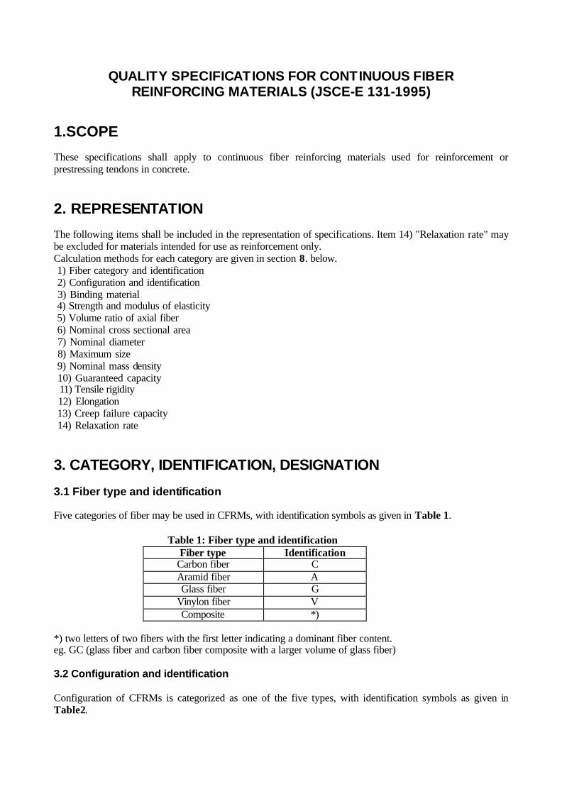
3. CATEGORY, IDENTIFICATION, DESIGNATION 3.1 Fiber type and identification Five categories of fiber may be used in CFRMs, with identification symbols as given in Table 1.
Table 1: Fiber type and identification Fiber type Identification
Carbon fiber C Aramid fiber A Glass fiber G
Vinylon fiber V Composite *)
*) two letters of two fibers with the first letter indicating a dominant fiber content. eg. GC (glass fiber and carbon fiber composite with a larger volume of glass fiber) 3.2 Configuration and identification Configuration of CFRMs is categorized as one of the five types, with identification symbols as given in Table2.

Table 2: Configuration categories and identification syrnboIs Category Rod Strand Braided Lattice Rectangular Symbol R, D *) S B L P Configuration
*) D = deformed 3.3 Designations Designations for CFRM fiber / configuration combinations are given in Table 3.
Table 3: Designations Fiber type Configuration Designation
Carbon Rod Strand
Braided Lattice
Rectangular
CR, CD CS CB CL CP
Aramid Rod Strand
Braided Lattice
Rectangular
AR,AD AS AB AL AP
Glass fiber Rod Strand
Braided Lattice
Rectangular
GR, GD GS GB GL GP
Vinylon Rod Strand
Braided Lattice
Rectangular
VR,VD VS VB VP VP
Composite Rod Strand
Braided Lattice
Rectangular
*)R, *)D *)S *)B *)L *)P
*) = initial letters of two fiber types, e.g. GC (glass fiber + carbon fiber composite)
4. QUALITY OF FIBER AND BINDING MATERIAL 4.1 Fibers Fibers used in CFRMs shall satisfy the quality specifications given in Table 4.
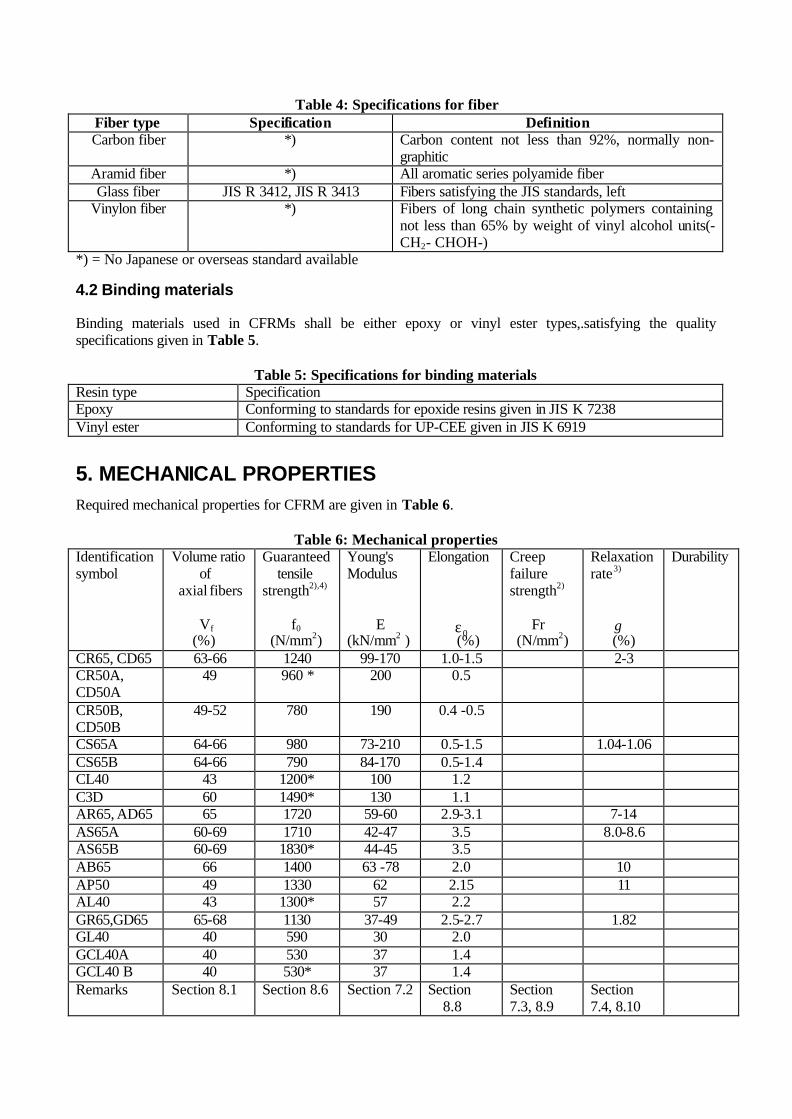
Table 4: Specifications for fiber Fiber type Specification Definition Carbon fiber *) Carbon content not less than 92%, normally non-
graphitic Aramid fiber *) All aromatic series polyamide fiber Glass fiber JIS R 3412, JIS R 3413 Fibers satisfying the JIS standards, left
Vinylon fiber *) Fibers of long chain synthetic polymers containing not less than 65% by weight of vinyl alcohol units(- CH2- CHOH-)
*) = No Japanese or overseas standard available
4.2 Binding materials Binding materials used in CFRMs shall be either epoxy or vinyl ester types,.satisfying the quality specifications given in Table 5.
Table 5: Specifications for binding materials Resin type Specification Epoxy Conforming to standards for epoxide resins given in JIS K 7238 Vinyl ester Conforming to standards for UP-CEE given in JIS K 6919
5. MECHANICAL PROPERTIES Required mechanical properties for CFRM are given in Table 6.
Table 6: Mechanical properties Identification symbol
Volume ratio of
axial fibers Vf
(%)
Guaranteed tensile
strength2),4)
f0
(N/mm2)
Young's Modulus
E
(kN/mm2 )
Elongation
0ε (%)
Creep failure strength2)
Fr (N/mm2)
Relaxation rate3)
γ (%)
Durability
CR65, CD65 63-66 1240 99-170 1.0-1.5 2-3 CR50A, CD50A
49 960 * 200 0.5
CR50B, CD50B
49-52 780 190 0.4 -0.5
CS65A 64-66 980 73-210 0.5-1.5 1.04-1.06 CS65B 64-66 790 84-170 0.5-1.4 CL40 43 1200* 100 1.2 C3D 60 1490* 130 1.1 AR65, AD65 65 1720 59-60 2.9-3.1 7-14 AS65A 60-69 1710 42-47 3.5 8.0-8.6 AS65B 60-69 1830* 44-45 3.5 AB65 66 1400 63 -78 2.0 10 AP50 49 1330 62 2.15 11 AL40 43 1300* 57 2.2 GR65,GD65 65-68 1130 37-49 2.5-2.7 1.82 GL40 40 590 30 2.0 GCL40A 40 530 37 1.4 GCL40 B 40 530* 37 1.4 Remarks Section 8.1 Section 8.6 Section 7.2 Section
8.8 Section 7.3, 8.9
Section 7.4, 8.10

1) A or B following identification symbol refers to nominal diameter D: A:D ≤ 20mm; B:D ≥ 20mm 2) Strength, such as guaranteed tensile strength and creep failure strength, is obtained by dividing capacity, such as guaranteed capacity and creep failure capacity, by nominal cross sectional area 3) Not official values because test method was not identical 4) Data marked * refer not to average of many products but to average of one product 5) A blank cell indicates insufficient data available at present
6. NOMINAL DIAMETER AND MAXIMUM SIZE Nominal diameter and maximum size are tested according to sections 8.3 and 8.4; the maximum size ranges are given in table 7 and 8. Blank cells indicate data unavailable. Table 7: Nominal diameters and maximum Size ranges (1)
Symbol D (mm) D max (mm) Remarks (Designation) 3 5
CFCC
9 9.0- 9.4 10 10.2- 10.6 12 12.5 - 12.8
Hiful CF (SNCP)
8 9.0- 9.4 10 10.9- ll.3 12
Hiful CF (ANCP)
5 7.9 9.8 12
Leadline PC-5 PC-D8 PC-D10 PC-D12
5 7.9 9.8
12.0 .
Leadline PC-R5 PC-R8 PC-R10 PC-Rl2
12.5 14.0 - 16.0 20
25,0
CD(D) (20ypes)
30.0 .
CFRP rod
5 7.5 10.5 12.5 12.4 - 13.4 15.2 15.0 - 15.8
CS (23 types)
17.8
CFCC
25 40 39.2 - 41.5
12.5
15 21 25 30
35
CFRP strand (standard)

15 25 30
CFRP strand (high strength)
12.5 15 21 25 30
35
CFRP strand (high elasticity)
4.7 3.0-5.4 7.1 4.7-7.9 9.1 6.1- 10.1 11.3 8.0 - 12.0 13.7 9.8 - 14.6
CL (6 types)
15.8 11.2-16.8
Nefmac C6 C10 C13 C16 C19 C22
C3D 10 BE3D 3 3.33 - 3.64
4 4.40 - 4189 6 6.86 - 7.36
7.4 8.02 - 8.56 8 8.88 - 9.87
Technora rod L (deformed)
3 2.95-3.05
4 3.94 - 4.06 6 5.82 - 6.01 8 7.80 - 8.01
Teclnora rod (round)
AR(D) (10 types)
7.5 7.70 - 8.10 Arapree 12.4 12.5 - 13.56 12.7 12.72 - 14.1
15.2A 15.29 - 16.68
15.2B' 15.31 - 16.72 17.8 17.92 - 19.21 19.3 19.32 - 20.92 20.3 20.51 - 22.3
AS (8 types)
21.8 21.93 - 22.95
Technora strand
7.3 8.1- 8.36 9 9.3 - 10.2
10.4 11.2- 12.3 12.7 13.7 - 14.6 14.7 16.1 - 16.6
FiBRA RA7 RA9 RA11 RA13 RA15
7.3 8.02 - 8.33 FiBRA FA7 9 9.2- 10.1 FA9
10.4 11.1- 12.2 FA11 12.7 13.6- 14.4 FA13
AB (10 types)
14.7 15.9- 16.6 FA15 5.4 7.6
AP (3 types)
10.6
Arapree
4.5 2.8-5.2 6.8 4.5 - 7.5 8.7 5.8- 9.6 10.8 7.7- ll.5
AL (5 types)
13.2 9.4- 14.0
Nefmac A6 A10 A13 A16 Al9

Table 8: Nominal diameters and maximum size ranges (2) Symbol D (mm) D max (mm) Remarks (Designation)
8 8.7- 9.0 10 10.5 - 10.9 12 12.6- 13.1
Hiful GF(SNGP)
8 8.7-9.0 10 10.8- 11.2
GR(D) (6 types)
12 13.0- 13.4
Hiful GF(ANG)
2.4 1.1-2.9 3.3 2.0-3.8 4.1 2.5-4.7 6.7 4.1-7.7 10 6.7- 11.1 12.9 8.6- 14.4 16 11.2- 16.8
GL (8 types)
l9.4 13.8 - 20.6
Nefmac G2 G3 G4 G6 G10 G13 G16 G19
6 VR(D) (2 types) 10
Claratec rod
GCL (6 types)A 7.1 4.4- 8.2 10.6 7.0- 11.8 13.7 9.2- 15.2 16.9 12.0 - 18.0 20.7 15.2- 21.4
23.8 17.4 - 24.6
Nefmac H6 H10 H13 H16 H19 H22
7. TEST 7.1 Sampling Test pieces shall be obtained as shown in Table 9.
Table 9: Sampling standards Nominal diameter Sampling standard Any nominal diameter Sample taken from either end of a length or part of length* of
CFRM * Minimum unit : 100 m
7.2 Test for tensile strength (1) Test for tensile strength shall be conducted in accordance with JSCE-E 531 "Test Method for Tensile Properties of Continuous Fiber Reinforcing Materials" (2) Tensile strength shall be obtained by dividing the maximum resistant load by the nominal cross sectional area. (3) Young’s modulus shall be obtained by dividing the tensile rigidity by the nominal cross sectional area. 7.3 Test for creep failure strength Test for creep failure strength shall be conducted in accordance with JSCE-E 533 "Test Method for Creep Failure of Continuous Fiber Reinforcing Materials".
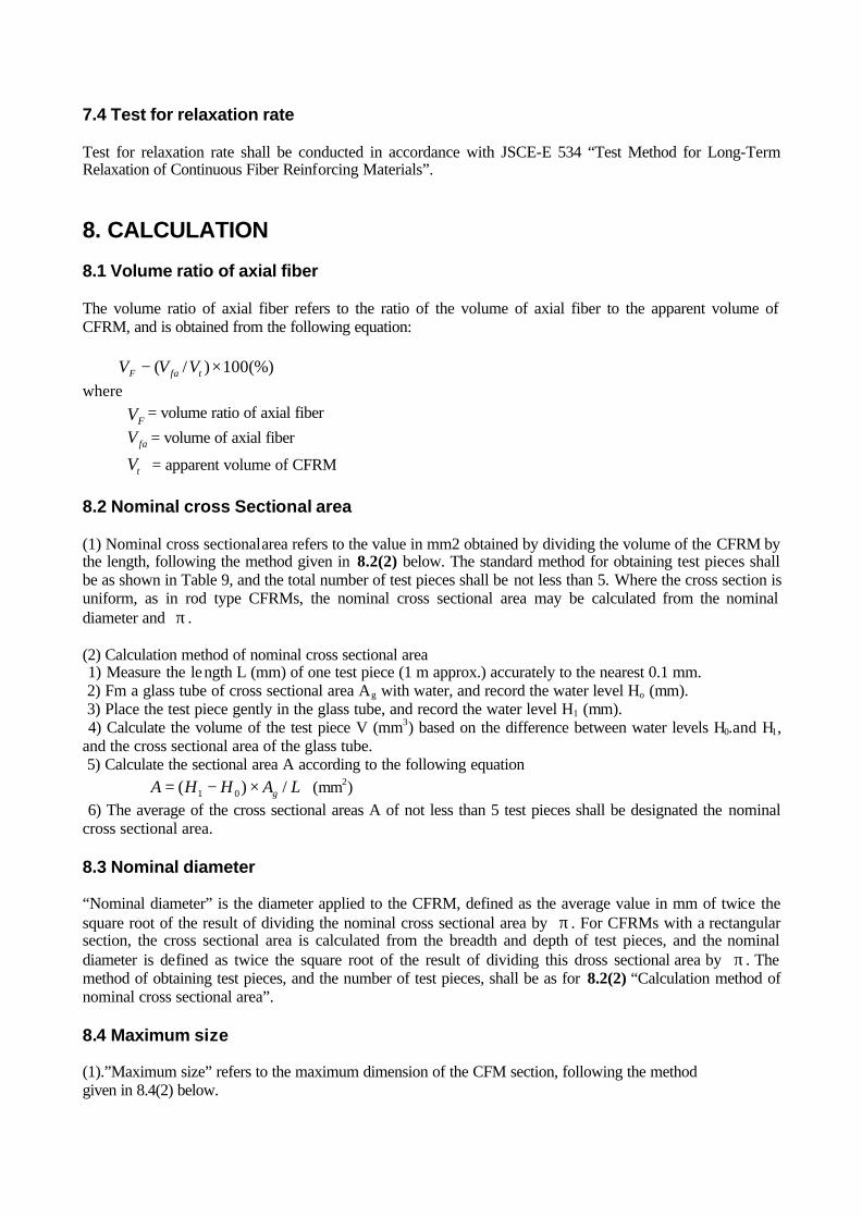
7.4 Test for relaxation rate Test for relaxation rate shall be conducted in accordance with JSCE-E 534 “Test Method for Long-Term Relaxation of Continuous Fiber Reinforcing Materials”.
8. CALCULATION 8.1 Volume ratio of axial fiber The volume ratio of axial fiber refers to the ratio of the volume of axial fiber to the apparent volume of CFRM, and is obtained from the following equation: (%)100)/( ×− tfaF VVV where
FV = volume ratio of axial fiber
faV = volume of axial fiber
tV = apparent volume of CFRM 8.2 Nominal cross Sectional area (1) Nominal cross sectional area refers to the value in mm2 obtained by dividing the volume of the CFRM by the length, following the method given in 8.2(2) below. The standard method for obtaining test pieces shall be as shown in Table 9, and the total number of test pieces shall be not less than 5. Where the cross section is uniform, as in rod type CFRMs, the nominal cross sectional area may be calculated from the nominal diameter and π . (2) Calculation method of nominal cross sectional area 1) Measure the length L (mm) of one test piece (1 m approx.) accurately to the nearest 0.1 mm. 2) Fm a glass tube of cross sectional area Ag with water, and record the water level Ho (mm). 3) Place the test piece gently in the glass tube, and record the water level H1 (mm). 4) Calculate the volume of the test piece V (mm3) based on the difference between water levels H0.and H1, and the cross sectional area of the glass tube. 5) Calculate the sectional area A according to the following equation
LAHHA g /)( 01 ×−= (mm2) 6) The average of the cross sectional areas A of not less than 5 test pieces shall be designated the nominal cross sectional area. 8.3 Nominal diameter “Nominal diameter” is the diameter applied to the CFRM, defined as the average value in mm of twice the square root of the result of dividing the nominal cross sectional area by π . For CFRMs with a rectangular section, the cross sectional area is calculated from the breadth and depth of test pieces, and the nominal diameter is defined as twice the square root of the result of dividing this dross sectional area by π . The method of obtaining test pieces, and the number of test pieces, shall be as for 8.2(2) “Calculation method of nominal cross sectional area”. 8.4 Maximum size (1).”Maximum size” refers to the maximum dimension of the CFM section, following the method given in 8.4(2) below.

(2) Calculation method of maximum size 1) Obtain a test piece of length 1 m. 2) For test pieces of not less than 5, measure the maximum diameter in the two orthogonal irections to the nearest 0.1 mm, at both ends and in the center of the test piece. 3) The maximum diameter of not less than 5 test pieces shall be designated as the maximum size. 8.5 Nominal mass density (1) Nominal mass density (g/m) is obtained by dividing the mass of CFM by the length, following the method given in 8.5(2) below. The standard method for obtaining test pieces shall be as shown in Table 9, and the total number of test pieces shall be not less than 5. (2) Calculation method of nominal mass density 1) Measure the mass of a test piece (length 1 m) to the nearest 0.1 g. 2) Measure the length of the test piece to the nearest 0.1 mm. 3) Calculate mass density by dividing the mass by the length. 4) The average of the mass densities of not less than 5 test pieces shall be designated the nominal mass
density. 8,6 Guaranteed capacity (1) Guaranteed capacity is the characteristic value of the tensile capacity of CFRM, following the method given in 8.6(2) below. The standard method for obtaining test pieces shall be as shown in Table 9, and the total number of test pieces shall be not less than 20. (2) Calculation method of guaranteed capacity Guaranteed capacity shall be not more than the value which is obtained by subtracting three times the standard deviation from the average of the test results of not less than 20 test pieces conducted in accordance with JSCE-E 531.”Test Method for Tensile Properties of Continuous Fiber Reinforcing Materials”, and is rounded off to the nearest 100 N. Test pieces failing at the anchorage shall be disregarded. 8.7 Tensile rigidity (1) Tensile rigidity shall be calculated following the method given in 8.7(2) below. The standard method for obtaining test pieces shall be as shown in Table 9, and the total number of test pieces shall be not less than 20. The data for calculation of the tensile rigidity may be obtained during the test for the guaranteed capacity. (2) Calculation method of tensile rigidity Tensile rigidity shall be the average value of the results of not less than 20 test pieces, each result being calculated according to the following equation, using the values from the load - strain curve obtained in accordance with JSCE-E 531 "Test Method for Tensile Properties of Continuous Fiber Reinforcing Materials" at 20% and 60% of the guaranteed capacity.
ε∆∆= /FEA where
EA = tensile rigidity (kN) F∆ = load increment from 20% to 60% of guaranteed capacity (kN) ε∆ = Strain increment from 20% to 60% of guaranteed capacity
8.8 Elongation (1) "Elongation" refers to the elongation corresponding to the guaranteed capacity, expressed as a percentage calculated following the method given in 8.8(2) below. The standard method for obtaining test pieces shall be
as shown in Table 9, and the total number of test pieces shall be not less than 20. The data for calculation of elongation may be obtained during the tensile test for the guaranteed capacity. (2) Calculation method of elongation 1) Calculate elongation corresponding to the guaranteed capacity of each test piece, from the test results obtained in accordance with JSCE-E 531 “Test Method for Tensile Properties of Continuous Fiber Reinforcing Materials”, for not less than 20 test pieces. 2) Elongation shall be defined as the average elongation of not less than 20 test results. 8.9 Creep failure capacity “Creep failure capacity” is obtained by multiplying the creep failure capacity ratio at 1 million hours, which is obtained by extrapolation of the load ratio - failure time approximation curve in which data are shown up to 1000 hours obtained in accordance with JSCE-E 533 “Test Method for Creep Failure of Continuous Fiber Reinforcing Materials”, by the guaranteed capacity. 8.10 Relaxation rate The relaxation rate is defined as the estimated relaxation after 1 million hours, which is obtained by extrapolation of the time - relaxation approximation curve in which data are shown up to 1000 hours obtained in accordance with JSCE-E 534 "Test Method for Long-Term Relaxation of Continuous Fiber Reinforcing Materials".
9. INSPECTION 9.1 Mechanical properties Mechanical properties shall be inspected following 7. TEST and 8 CALCULATION, confirming that the results conform to the mechanical properties listed in 5 MECHANICAL PROPERTIES. 9.2 Dimensions Dimensions shall be measured according to 8 CALCULATION, confirming that the results conform to the values given in 6. NOMINAL DIAMETER AND MAXIMUM SIZE.

TEST METHODS FOR CONTINUOUS FIBER REINFORCING MATERIALS
CONTENTS TEST METHOD FOR TENSILE PROPERTIES OF CONTINUOUS FIBER REINFORCING MATERIALS (JSCE-E 531-1995)................................................................................................................................93 TEST METHOD FOR FLEXURAL TENSILE PROPERTIES OF CONTINUOUS FIBER REINFORCING MATERIALS (JSCE-E 532-1995) ..........................................................................................................97 TEST METHOD FOR CREEP FAILURE OF CONTINUOUS FIBER REINFORCING MATERIALS (JSCE-E 533-1995).............................................................................................................................. 100 TEST METHOD FOR LONG-TERM RELAXATION OF CONTINUOUS FIBER REINFORCING MATERIALS (JSCE-E 534-l995) ......................................................................................................... 104 TEST METHOD FOR TENSILE FATIGUE OF CONTINUOUS FIBER REINFORCING MATERIALS (JSCE-E 535-1995).............................................................................................................................. 108 TEST METHOD FOR COEFFICIENT OF THERMAL EXPANSION OF CONTINUOUS FIBER REINFORCING MATERIALS BY THERMO-MECHANICAL ANALYSIS (JSCE-E 536-1995) .............111 TEST METHOD FOR PERFORMNCE OF ANCHORAGES AND COUPLERS IN PRESTRESSED CONCRETE USING CONTINUOUS FIBER REINFORCING MATERIALS (JSCE-E 537-1995) .......... 114 TEST METHOD FOR ALKALI RESISTANCE OF CONTINUOUS FIBER REINFORCING MATERIAS (JSCE-E 538-1995).............................................................................................................................. 118 TEST METHOD FOR BOND STRENGTH OF CONTINUOUS FIBER REINFORCING MATERIALS BY PULL-OUT TESTING (JSCE-E 539-1995)........................................................................................... 122 TEST METHOD FOR SHEAR PROPERTIES OF CONTINUOUS FIBER REINFORCING MATERIALS BY DOUBLE PLANE SHEAR (JSCE-E 540-1995) .............................................................................. 127
TEST METHOD FOR TENSILE PROPERTIES OF CONTINUOUS FIBER REINFORCING MATERIALS (JSCE-E 53l-l995)
1.SCOPE This specifications specifies mainly the test method for tensile properties of CFRM used in place of steel reinforcement or prestressing tendon in concrete.
2. DEFINITION The following terms are defined for general use in this Specifications, in addition to the terms used in the “Recommendation for Design and Construction for Concrete Structures using Continuous Fiber Reinforcing Materials'' and the “Quality Specifications for Continuous Fiber Reinforcing Materials”: (1) Test section: The part of a test piece subject to testing between the anchoring sections of the test piece (2) Anchoring section: The end part of a test piece where an anchorage is fitted to transmit loads from the testing machine to the test section (3) Gauge length: The distance between two gauge points on the test section providing a reference length for strain measurements (4) Anchorage : Device fitted to the anchoring section of a test piece to transmit loads from the testing machine to the test piece (5) Tensile capacity: The tensile load at the time of failure of the test piece (6) Guaranteed tensile capacity: Guaranteed value for the tensile capacity; if none is specified, the manufacturer’s guaranteed tensile capacity shall be adopted (7) Ultimate strain: Strain corresponding to the tensile capacity
3. TEST PIECES 3.1 Preparation of test pieces Test pieces shall as a rule not be subjected to any processing. For mesh-type CFRM, linear test pieces may be prepared by cutting away extraneous parts in such a way as not to affect the performance of the part to be tested. However, processing will be permissible for anchoring sections to be provided in the test piece. 3.2 Handling of test pieces During the sampling and preparation of test pieces, all deformation, heating, outdoor exposure to ultraviolet light etc. causing changes to the material properties of the test section of the test piece must be avoided. 3.3 Length of test pieces The length of the test piece shall be the length of the test section added to the length of the anchoring section. The length of the test section shall be not less than 100mm, and not less than 40 times the nominal diameter of the CFRM. Fort CFRM in strand form, as an additional condition, the length shall be more than 2 times the strand pitch. 3.4 Number of test pieces The number of test pieces shall not be less than five. If the test piece is found clearly to have failed at the anchoring section, or to have slipped out of the anchoring section, an additional test shall be performed on a separate test piece taken from the same lot.

4. TESTING MACHINE AND DEVICES 4.1 Testing machine The testing machine to be used in tensile testing shall conform to JIS B 7721 (Tensile Testing Machines). The testing machine shall have a loading capacity in excess of the tensile capacity of the test piece, and shall be capable of applying loading at the required loading rate. 4.2 Anchorage The anchorage shall be suited to the geometry of the test piece, and shall have the capacity to transmit loads capable to cause the test piece to fail at the test section. The anchorage shall constructed so as to transmit loads reliably from the testing machine to the test section, transmitting axial loads only to the test piece, without transmitting either torsion or flexural force. 4.3 Extensometer and strain gauge The extensometer and strain gauge shall be capable of recording all variations in gauge length or elongation during testing, with an accuracy of not less than 10× 10-6.
5. TEST TEMPERATURE The specifications test temperature shall generally be within the range 5~35 Co . The test temperature for test pieces sensitive to temperature variations shall be 20± 2 Co
6. TEST METHOD 6.1 Mounting of test piece When mounting the test piece on the testing machine, care must be taken to ensure that the longer axis of the test piece coincides with the imaginary line joining the two anchorages fitted to the testing machine. 6.2 Mounting of extensometer and strain gauge In order to determine the Young's modulus and ultimate strain of the test piece, an extensometer or strain gauges shall be mounted in the center of the test section at a distance of at least 8 times the nominal diameter of the CFRM from the anchorages, correctly in the direction of tensioning. The gauge length when using an extensometer shall not be less than 8 times the nominal diameter of the CFRM. The gauge length for stranded CFRM shall not be less than 8 times the nominal diameter of the CFRM, and not less than the length of the stranding pitch. 6.3 Loading rate The specifications rate of loading the test piece shall be between 100~500 N/mm2 per minute. If a strain control type of testing machine is used, loading shall be applied to the test piece at a fixed strain rate corresponding to 100~500 N/ mm2 per minute. 6.4 Scope of test The loading shall be completed until tensile failure, and the measurements shall be recorded until the strain reaches at least 60% of the tensile capacity or the guaranteed tensile capacity.

7. CALCULATION AND EXPRESSION OF TEST RESULTS 7.1 Handling of data The material properties of CFRM shall be assessed on the basis only of test pieces undergoing failure in the test section. In cases where tensile failure or slippage has clearly taken place at the anchoring section, the data shall be disregarded and additional tests shall be performed until the number of test pieces failing in the test section is not less than five. 7.2 Load-displacement curve A load (stress) ~ displacement (strain) curve shall be derived from load or stress and strain measurements recorded. 7.3 Tensile strength Tensile strength shall be calculated according to Eq. (1), rounded off to three significant digits.
AFf uu /− (1) where uf = tensile strength (N/mm2)
uF = tensile capacity (N) A = nominal cross sectional area of a test piece (mm2) 7.4 Tensile rigidity and Young's modulus Tensile rigidity and Young's modulus shall be calculated from the load difference between 20% and 60% of tensile capacity according to the load-strain curve obtained from extensometer or strain gauge readings according to Eq. (2) and (3), rounded off to three significant digits. For materials where a guaranteed tensile capacity is set, the values at 20% and 60% of the guaranteed tensile capacity may be used.
ε∆∆= /FEA (2)
AF
E⋅∆
∆=
ε (3)
where
EA = tensile rigidity (N) E = Young's modulus (N/mm2)
F∆ = difference between loads at 20% and 60% of tensile failure capacity or guaranteed tensile capacity
ε∆ = strain difference between the above two points 7.5 Ultimate strain Ultimate strain shall be the strain corresponding to the tensile failure capacity when strain gauge measurements of the test piece are available up to failure. If extensometer etc. measurements could not be made until failure, ultimate strain shall be calculated from the tensile capacity and Young's modulus according to Eq. (4), rounded off to three significant digits.
EAFu
u =ε (4)
where
uε = ultimate strain

8. TEST REPORT The test report shall include the following items: (1) Name of CFRM (2) Type of fiber and fiber binding material, volume ratio of fiber (3) Numbers or identification marks of test pieces (4) Designation, nominal diameter, nominal cross sectional area (5) Date of test, test temperature, loading rate (6) Tensile capacity for each test piece, averages and specifications deviations for tensile capacity and tensile strength (7) Tensile rigidity and Young's modulus for each test piece, and averages (8) Ultimate strain for each test piece, and averages (9) Stress-strain curve for each test piece
TEST METHOD FOR FLEXURAL TENSILE PROPERTIES OF CONTINUOUS FIBER REINFORCING MATERIALS (JSCE-E 532-1995)
1.SCOPE This specifications specifies mainly the test method for flexural tensile properties of bent CFRM used in place of steel reinforcement or prestressing tendon in concrete.
2. DEFINITIONS The following terms are defined for general use in this Specifications, in addition to the terms used in the “Recommendation for Design and Construction for Concrete Structures using Continuous Fiber Reinforcing Materials”, the “Quality Specifications for Continuous Fiber Reinforcing Materials” and the “Test Method for Tensile Properties of Continuous Fiber Reinforcing Materials”: (1) Deflected section: Section of a CFRM which is bent and maintained at the required bending angle and bending diameter ratio (2) Deflector: Device used to maintain the position, alter the bending angle, or alleviate the stress concentrations in the CFRM; sometimes installed in the deflected section (3) Bending angle: Angle formed by the straight sections of a test piece on either side of the deflector (4) Bending diameter ratio: Ratio of the external diameter of the deflector surface in contact with the CFRM, and the nominal diameter of the CFRM (5) Bending tensile capacity: Tensile load at the moment of failure of the test piece
3. TEST PIECES 3.1 Preparation and handling of test pieces Test pieces shall be prepared and handled in accordance with the “Test Method for Tensile Properties of Continuous Fiber Reinforcing Materials”. 3.2 Length of test pieces The length of the test piece shall be the length of the test section added to the length of the anchoring section. The length of the test section shall not be less than 100mm from the anchorages to the deflected section, and not less than 40 times the nominal diameter of the CFRM. For CFRM in strand form, as an additional condition, the length shall be not less than 2 times the strand pitch. 3.3 Number of test pieces The number of test pieces shall not be less than three for each test condition (combination of bending diameters and bending angles). If the test piece is found clearly to have failed at the anchoring section, or to have slipped out of the anchoring section, an additional test shall be performed on a separate test piece taken from the same lot.
4. TESTING MACHINE AND DEVICES 4.1 Testing machine The testing machine must include a loading device, load indicator, anchorages holder and deflector. The testing machine must also have a structure capable of continuing the test up to the tensile failure.
4.2 Loading device The loading device shall have a loading capacity in excess of the tensile capacity of the test piece, and shall be capable of applying loading at the required loading rate. 4.3 Load indicator The load indicator must be capable of displaying loads with an accuracy of not less than 1% of the failure load, up to failure of the test piece. 4.4 Anchorage holder The anchorage holder must be suited to the geometry of the test piece, and must be capable of accurately transmitting loads from the testing machine to the test piece. It must be structured so as to transmit axial loads only to the test piece, without transmitting either torsion or flexural force. 4.5 Deflector The deflector must be capable of maintaining the required bending angle and bending diameter during the test until failure of the test piece. The surface of the deflector in contact with the test piece must be robust and smooth.
5. TEST TEMPERATURE The specifications test temperature shall generally be within the range 5~35 Co . The test temperature for test pieces sensitive to temperature variations shall be 20± 2 Co .
6. TEST METHOD 6.1 Test preparation The bending diameter and bending angle shall be set appropriately for the test. This combination then forms a single test condition. As a specifications configuration, only one deflected section shall be set up in the test piece. 6.2 Mounting of test piece Care shall be taken when mounting the test piece on the testing machine to maintain the required bending angle and bending diameter at the deflected section during the test. 6.3 Loading rate The specifications rate of loading the test piece shall be between 100~500 N/mm2 per minute. 6.4 Scope of test Loading shall be applied until failure of the test piece. Lead and failure location shall be measured and recorded at the time of failure.
7. CALCULATION AND EXPRESSION OF TEST RESULTS 7.1 Handling of data The material properties of CFRM shall be assessed on the basis only of test pieces undergoing failure in the test section. In cases where tensile failure or slippage has clearly taken place at the anchoring section, the data shall be disregarded and additional tests shall be performed until the number of test pieces failing in the test section is not less than three.
7.2 Bending tensile capacity The average, maximum, minimum, and specifications deviation of the bending tensile capacity for each set of test conditions shall be calculated. 7.3 Failure patterns The location and mode of failure shall be observed and recorded for each test piece.
8. TEST REPORT The test report shall include the following items: (l) Name of CFRM (2) Type of fiber and fiber binding material, volume ratio of fiber (3) Numbers or identification marks of test pieces (4) Designation, nominal diameter, maximum cross sectional area (5) Date of test, test temperature, loading rate (6) Condition of surface of CFRM (material, thickness, configuration etc. of any coating, etc.) (7) Bending angle, external diameter of surface position of deflected section, bending diameter ratio, material and surface configuration (8) Bending tensile capacity for each test piece (9) Location and mode of failure for each test piece (10) Numbers of test pieces for each set of conditions in (7); average, maximum, minimum, and specifications deviation of the bending tensile capacity

TEST METHOD FOR CREEP FAILURE OF CONTINUOUS FIBER REINFORCING MATERIALS (JSCE-E 533-1995)
1.SCOPE This specifications specifies mainly the test method for creep failure of CFRM used in place of steel reinforcement or prestressing tendon in concrete.
2. DEFINITIONS The following terms are defined for general use in this Specifications, in addition to the terms used in the “Recommendation for Design and Construction for Concrete Structures using Continuous Fiber Reinforcing Materials” and the “Quality Specifications for Continuous Fiber Reinforcing Materials”: (1) Creep: Time-dependent deformation when CFRM is subjected to a sustained constant load at a constant temperature (2) Creep strain: Strain occurring in a test piece due to creep (3) Creep failure: Failure occurring in a test piece due a sustained load (4) Creep failure time: Time between start of a sustained load, and failure of the test piece (5) Creep failure capacity: Lead causing failure after a specified period of time from the start of a sustained load. In particular, the load causing failure after 1 million hours is referred to as the million hour creep failure capacity. (6) Creep failure strength: Stress causing failure after a specified period of time from the start of a sustained load. In particular, the stress causing failure after 1 million hours is referred to as the million hour creep failure strength. (7) Load ratio: Ratio of a constant sustained load applied to a test piece, and the tensile failure load
3. TEST PTECES 3.1 Preparation, handling and dimensions of test pieces Test pieces shall be prepared and handled in accordance with the “'Test Method for Tensile Properties of Continuous Fiber Reinforcing Materials”. 3.2 Number of test pieces The number of test pieces for each test condition shall not be less than three. If the test piece is found clearly to have failed at the anchoring section, or to have slipped out of the anchoring section, an additional test shall be performed on a separate test piece taken from the same lot.
4. TESTING MACHINE AND DEVICES 4.1 Testing machine The testing machine must be capable of maintaining constant, sustained loading even during deformation of the test piece. 4.2 Anchorage The anchorage must be in accordance with the “Test Method for Tensile Properties of Continuous Fiber Reinforcing Materials”.

4.3 Extensometer and strain gauge The extensometer and strain gauge must be in accordance with the "Test Method for Tensile Properties of Continuous Fiber Reinforcing Materials''. 4.4 Hour meter The hour meter for measuring the passage of time must be accurate to within 1% of the elapsed time.
5. TEST TEMPERATURE The test temperature shall normally be within the range 20± 2 Co , except in special circumstances.
6. TENSILE CAPACITY The tensile capacity shall be calculated in accordance with the ''Test Method for Tensile Properties of Continuous Fiber Reinforcing Materials".
7. TEST METHOD 7.1 Mounting of test piece, and gauge distance Mounting of test pieces and gauge length shall be in accordance with the “Test Method for Tensile Properties of Continuous Fiber Reinforcing Materials”. 7.2 Loading (1) Care must be taken during loading to prevent the test piece from being subjected to any shock or vibration. (2) Creep test measurement is considered to start at the moment when of the prescribed load to the test piece has been completed. 7.3 Selection of sustained loads to be applied (1) Creep tests must be conducted for not less than five sets of load ratio conditions, selected on the basis of the tensile capacity. (2) One set of load ratio conditions must be such that three test pieces must not fail after 1000 hours of loading. 7.4 Measurement of creep strain Creep strain shall be recorded automatically by a recorder attached to the testing machine. If no recorder is attached to the testing machine, creep strain shall be measured and recorded after the following times have elapsed: 1, 3, 6, 9, 15, 30, 45 minutes; 1, 1.5, 2, 4, 10, 24, 48, 72, 96, 120 hours; and in general every 24
hours subsequently, with a minimum of one measurement in every 120 hours.
8. CALCULATION AND EXPRESSION OF TEST RESULTS 8.1 Handling of data The material properties of CFRM shall be assessed on the basis only of test pieces undergoing failure in the test section. In cases where tensile failure or slippage has clearly taken place at the anchoring section, the data shall be disregarded and additional tests shall be performed until the number of test pieces failing in the test section is not less than three.

Data for test pieces breaking at the start of loading shall be disregarded. In such cases, the applied load and the creep failure time only shall be recorded but excluded from the data, although no additional tests need be performed. 8.2 Load ratio - creep failure time curve For each test piece subjected to creep test, the load ratio - creep failure time curve shall be plotted on a semi-logarithmic graph where the load ratio is represented on an arithmetic scale on the vertical axis, and creep failure time in hours is represented on an logarithmic scale on the horizontal axis. 8.3 Creep failure line chart A creep failure line chart shall be prepared, calculating an approximation line from the graph data by the least-squares method according to Eq. (1).
TbaY log−= (1) where
Y load ratio ba, = empirical constants
T = time (h) 8.4 Creep failure capacity and creep failure strength The load ratio at 1 million hours (approximately 114 years) determined from the calculated approximation line shall be the creep failure load ratio; the load and stress corresponding to this creep failure load ratio shall be the million hour creep failure capacity and the million hour creep failure strength respectively. The million hour creep failure strength shall be calculated according to Eq. (2), rounded off to three significant figures
AFf rr /= (2) where
rf = million hour creep failure strength (N/ mm2)
rF = million hour creep failure capacity (N) A = nominal cross sectional area of test piece (mm2)
9. TEST REPORT The test report shall include the following items: (1) Name of CFRM (2) Type of fiber and fiber binding material, volume ratio of fiber (3) Numbers or identification marks of test pieces (4) Designation, nominal diameter, maximum cross sectional area (5) Date of test, test temperature (6) Type and name of test machine (7) Type and name of anchorage (8) Tensile capacity, and average tensile capacity and tensile strength for each test piece (9) Lead ratios and creep failure time curve for each test piece (10) Formula for derivation of approximation line (11) Creep failure load ratio, million hour creep failure capacity and million hour creep failure strength

TEST METHOD FOR LONG-TERM RELAXATION OF CONTINUOUS FIBER REINFORCING MATERIALS (JSCE-E 534-1995)
1.SCOPE This specifications specifies mainly the test method for evaluating the relaxation ratio for long-term relaxation under a given constant temperature and strain, for CFRM used in place of steel reinforcement or prestressing tendon in concrete.
2. DEFINITIONS The following terms are defined for general use in this Specifications, in addition to the terms used in the “Recommendation for Design and Construction for Concrete Structures using Continuous Fiber Reinforcing Materials” and the “'Quality Specifications for Continuous Fiber Reinforcing Materials”: (1) Relaxation: Refers to stress relaxation: the time-dependent decrease in load in a CFRM held at a given constant temperature with a prescribed initial load applied and held at a given constant strain; (2) Relaxation rate: Percentage reduction of loading relative to the initial load after a given period of time when an initial load is applied and the strain fixed. In particular, the relaxation value after 1 million hours (approximately 114 years) is referred to as the million year relaxation rate. (3) Tensile capacity: The average of the tensile failure loads determined based on tests conducted in according with the “Test Method for Tensile Testing of Continuous Fiber Reinforcing Materials”. The test temperature shall normally be within the range 20± 2 Co , except in special circumstances.
3. TEST PIECES 3.1 Preparation, handling and dimensions of test pieces Test pieces shall be prepared and handled in accordance with the "Test Method for Tensile Properties of Continuous Fiber Reinforcing Materials". 3.2 Number of test pieces The number of test pieces for each test condition shall not be less than three. If the test piece is found clearly to have failed at the anchoring section, or to have slipped out of the anchoring section, an additional test shall be performed on a separate test piece taken from the same lot.
4. TESTING MACHINE AND DEVICES 4.1 Testing machine The testing machine must be capable of applying a sustained load while maintaining a constant length. The machine must be capable of loading at a rate of 200± 50 N/mm2 per minute. 4.2 Anchorage The anchorage must be in accordance with the ''Test Method for Tensile Properties of Continuous Fiber Reinforcing Materials". 4.3 Accuracy of initial load The accuracy of the initial load applied to the test piece shall be as follows: Test machines with loading capacity of equal to or less than 1 kN: ± 1.0% of set load

Test machines with loading capacity of more than 1 kN: ± 2.0% of set load 4.4 Accuracy of load measurements The accuracy of readings or automatic recording of loads applied to the test piece shall be within 0.1% of the initial load. 4.5 Strain fluctuations The test machine shall control strain fluctuations no greater than ± 25 × 10-6 in the test piece throughout the test period, once the strain in the test piece has been fixed. If the CFRM slips from the anchoring section, the distance of slippage shall be compensated so as not to affect the test results. 4.6 Extensometer and strain gauge If an extensometer or strain gauge is to be fitted to the test piece, the extensometer or strain gauge shall be in accordance with the “Test Method for Tensile Properties of Continuous Fiber Reinforcing Materials”'. 4.7 Hour meter The hour meter for measuring the passage of time must be accurate to within 1% of the elapsed time.
5. TEST TEMPERATURE The test temperature shall normally be within the range 20 ± 2 Co , except in special circumstances. Where the test results are heavily dependent on temperature, additional tests shall be performed at 0 Co and at 60 Co . In either case, temperature fluctuation over the test period shall be not more than ± 2 Co .
6. TEST METHOD 6.1 Mounting of test piece and gauge length Mounting of test pieces and gauge length shall be in accordance with the "Test Method for Tensile Properties of Continuous Fiber Reinforcing Materials". 6.2 Prestretching If a strain gauge is to be set to the test piece, the test piece shall first be stretched taut by applying a load of 10~40% of the prescribed initial load, thereafter the strain gauge shall be attached and correctly calibrated. 6.3 Initial load The initial load shall be either 70% of the guaranteed tensile capacity, or 80% of the million hour creep failure capacity, whichever is the smaller. 6.4 Application of initial load (1) The initial load must be applied without subjecting the test piece to any shock or vibration. (2) The specifications rate of loading the test piece shall be between 200± 50 N/ mm2 per minute. (3) The strain on the test piece shall be fixed after the initial load has been applied to the test piece, and maintained for 120± 2 seconds. This time shall be deemed to be the test start time. 6.5 Measurement of load reduction Lead reduction shall generally be measured over a period of at least 1000 hours. Lead reduction shall be recorded automatically by a recorder attached to the testing machine. If no recorder is attached to the testing machine, load reduction shall be measured and recorded after the following times have elapsed:
1, 3, 6, 9, 15, 30, 45 minutes; 1, 1.5, 2, 4, 10, 24, 48, 72, 96, 120hours; and in general every 24 hours subsequently, at a minimum of one measurement every 120 hours.

7. CALCULATION AND EXPRESSION OF TEST RESULTS 7.1 Relaxation value The relaxation value shall be calculated by dividing the load measured in the relaxation test by the initial load. 7.2 Relaxation curve The relaxation curve shall be plotted on a semi-logarithmic graph where the relaxation value (%) is represented on an arithmetic scale on the vertical axis, and test time in hours is represented on an logarithmic scale on the horizontal axis. An approximation line for Eq. (1) shall be derived from the graph data using the least-square method.
TbaY log−= (1) where
Y = relaxation rate (%) ba, = empirical constants
T = time (h) 7.4 Million hour relaxation rate The relaxation rate after 1 million hours (approximately 114 years) shall be evaluated from the approximation line; this value represents the million hour relaxation rate. Where the service life of the structure in which the CFRM is to be used is determined in advance, the relaxation rate for the number of years of service life (“'service life relaxation rate”) shall also be determined.
8. TEST REPORT The test report shall include the following items: (1) Name of CFRM (2) Type of fiber and fiber binding material, volume ratio of fiber (3) Numbers or identification marks of test pieces (4) Designation, nominal diameter, nominal cross sectional area (5) Date of test, test temperature and temperature fluctuations (6) Type of test machine (7) Initial load and loading rate of initial load (8) Guaranteed tensile capacity, and ratio of initial load to guaranteed tensile capacity (9) Relaxation curve for each test piece (10) Average relaxation rates at 10, 120 and 1000 hours (1l) Formula for derivation of an approximation line (12) Million hour relaxation rate (13) Relaxation rate corresponding to design service life allowed for in design ("service life relaxation rate"), where applicable

TEST METHOD FOR TENSILE FAT IGUE OF CONTINUOUS FIBER REINFORCING MATERIALS (JSCE-E 535-1995)
1.SCOPE This specifications specifies mainly the test method for tensile fatigue under constant tensile loading for CFRM used in place of steel reinforcement or prestressing tendon in concrete.
2. DEFINITIONS The following terms are defined for general use in this Specifications, in addition to the terms used in the “Recommendation for Design and Construction for Concrete Structures using Continuous Fiber Reinforcing Materials", the "Quality Specifications for Continuous Fiber Reinforcing Materials", and the "Test Method for Tensile Properties of Continuous Fiber Reinforcing Materials”: (1) Repeated load (stress): Load (stress) alternating simply and cyclically between fixed maximum and minimum values (2) Maximum repeated load (stress): Maximum load (stress) during repeated loading (stressing) (3) Minimum repeated load (stress): Minimum load (stress) during repeated loading (stressing) (4) Lead (stress) range: Difference between maximum and minimum repeated load (stress) (5) Load (stress) amplitude: One-half of the load (stress) range (6) Average load (stress): Average of the maximum and minimum repeated load (stress) (7) Number of cycles: Number of times the repeated load (stress) is applied to the test piece (8) S-N curve: Curve plotted in a graph with repeated stress on the vertical axis and the number of cycles to fatigue failure on the horizontal axis (9) Fatigue strength: Maximum repeated stress at which the test piece does not fail at the prescribed number of cycles (10) Frequency: Number of loading (stressing) cycles in one second during the test
3. TEST PIECES 3.1 Preparation, handling and dimensions of test pieces Preparation, handling and dimensions of test pieces shall be in accordance with the "Test Method for tensile Properties of Continuous Fiber Reinforcing Materials”. 3.2 Number of test pieces The number of test pieces should be at least three, for each of at least three levels of loading (stress). If the test piece is found clearly to have failed at the anchoring section, or to have slipped out of the anchoring section, an additional test shall be performed on a separate test piece taken from the same lot.
4. TESTLNG MACHINE AND DEVICES 4.1 Testing machine The testing machine shall be capable of maintaining a constant load (stress) amplitude, maximum and minimum repeated load (stress), and frequency. The testing machine shall be fitted with a counter capable of recording the number of cycles to failure of the test piece. The accuracy of the load shall be within 1% of the load range.

4.2 Anchorage The anchorage must be in accordance with the "Test Method for Tensile Properties of Continuous Fiber Reinforcing Materials". Ideally the same type of anchorage should be used for all in a given series of tests. 4.3 Strain measurements If strain measurements are required as part of the fatigue tests, an extensometer and strain gauge capable of maintaining an accuracy of ± 1% of the indicated value during the test shall be used.
5. TEST TEMPERATURE The test temperature shall generally be within the range 5~35 Co . The specifications test temperature for test pieces sensitive to temperature variations shall be 20± 2 Co
6. TEST METHOD 6.1 Mounting of test pieces Mounting of test pieces shall be in accordance with the Test Method for Tensile Properties of Continuous Fiber Reinforcing Materials". 6.2 Load setting Lead may be set in two ways: either fixing the average load and varying the load amplitude, or fixing the minimum repeated load by partial pulsation and varying the maximum repeated load. The method adopted shall be determined according to the purpose of the test. In either case, at least three load levels shall be set within the range of number of cycles to failure 103 to 2× 10⁶. 6.3 Frequency The frequency shall normally be within the range 1~10 Hz. 6.4 Start of test After static loading up to the average load, repeated loading shall be commenced. The prescribed load shall be introduced rapidly and without any shock. The maximum and minimum repeated loads shall remain constant for the duration of the test. Counting of the number of cycles shall normally commence when the load on the test piece has reached the prescribed load. 6.5 End of test Complete separation (breaking) of the test piece shall be deemed to constitute failure, and the number of cycles to failure shall be recorded. If the test piece doesn't fail after 2× 10⁶ cycles, the test may be discontinued. Test pieces that did not fail must not be reused. 6.6 Interruption of test Tests shall normally be conducted without interruption for each test piece from the start of the test to the end of the test. When a test is interrupted, the number of cycles up to the time of interruption, and the period of the interruption shall be recorded.
7. CALCULATION AND EXPRESSION OF TEST RESULTS 7.1 Handing of data Data for test pieces that slipped from the anchoring section shall be disregarded in assessing the material properties of the CFRM. In cases where tensile failure or slippage has clearly taken place at the anchoring section, the data shall be disregarded and additional tests shall be performed until the number of test pieces

failing in the test section is not less than three. 7.2 S-N curve The S-N curve shall be plotted with the maximum repeated stress, stress range or stress amplitude represented on an arithmetic scale on the vertical axis, and the number of cycles represented on a logarithmic scale on the horizontal axis. Where measurement points coincide, the number of coinciding points shall be noted. Right-facing arrows shall be added to indicate points representing test results for test pieces remaining that did not fail. 7.3 Fatigue strength The fatigue strength after 2× 10⁶ cycles shall be derived from the S-N curve. The fatigue strength shall be rounded off to three significant digits.
8. TEST REPORT The test report shall include the following items: (1) Name of CFRM (2) Type of fiber and fiber binding material, volume ratio of fiber (3) Numbers or identification marks of test pieces (4) Designation, nominal diameter, maximum cross sectional area (5) Date of test, test temperature and humidity (from start to end of test) (6) Maximum load (stress), minimum load (stress), load (stress range), number of cycles to failure, and frequency rate for each test piece (7) Record of observed failure mode for each test piece (8) S-N curve

TEST METHOD FOR COEFFICIENT OF THERMAL EXPANSION OF CONTINUOUS FIBER REINFORCING MATERIALS BY
THERMO-MECHANICAL ANALYSIS (JSCE-E 536-1995)
1.SCOPE This specifications specifies mainly the test method for measuring the coefficient of thermal expansion of CFRM used in place of steel reinforcement or prestressing tendon in concrete by thermomechanical analysis.
2. DEFINITIONS The following terms are defined for general use in this Specifications, in addition to the terms used in the ”Recommendation for Design and Construction for Concrete Structures using Continuous Fiber Reinforcing Materials'' and the “Quality Specifications for Continuous Fiber Reinforcing Materials": (1)The analysis (TMA): Method for measuring deformation of a material as a function of either temperature or time, by varying the temperature of the material according to a calibrated program, under a non-vibrating load (2) TMA curve: In the context of TMA, a graph with temperature or time represented on the horizontal axis, and deformation on the vertical axis (3) Coefficient of thermal expansion: the average coefficient of linear thermal expansion between given temperatures. The average of the given temperatures is taken as the representative temperature.
3. TEST PIECES 3.1 Pre-test curing of test pieces Prior to testing, test pieces shall normally be kept for a minimum of 24 hours at a temperature of 20± 2 Co and relative humidity of 65± 5%, under Specifications Temperature Conditions Class 2 and Specifications Humidity Conditions Class2, in accordance with JIS K 7100. The test pieces shall then normally be kept for 48 hours at the maximum test temperature, in order to eliminate strain resulting from bending, and for dehumidification and deaeration. 3.2 Dimensions of test piece The specifications test piece cut from the CFRM shall be 20mm in length, with a round or square cross-section of diameter or breadth of not more than 5mm. 3.3 Number of test pieces The number of test pieces shall be not less than three.
4. TESTING DEVICE 4.1 Testing device The TMA apparatus used for testing shall be capable of measuring in compression mode, of maintaining a constant atmosphere around the test piece, and of raising the temperature of the test piece at a constant rate. 4.2 Calibration of testing device (I) Sensitivity calibration of the displacement gauge shall be carried out periodically using either an external micrometer as defined in JIS B 7502, or a micrometer attached to the testing machine.

(2) Calibration of the temperature gauge shall be carried out using a pure substance of known melting point. 4.3 Installation of testing device The TMA apparatus must be installed in a location not subject to vibration during testing.
5. TEST METHOD 5.1 Mounting of test piece The test piece, gauge rod and test platform shall be cleaned, and the test piece placed upright and if possible bonded to the platform. 5.2 The gauge rod shall be placed in the center of the test piece, with no pressure applied. 5.3 The atmosphere around the test piece shall consist of dry air (water content not more than 0.1% w/w) or nitrogen (water content not more than 0.001% w/w, oxygen content not more than 0.001% w/w), maintained at a flow rate in the range of 50~100 ml /min. 5.4 The load shall be applied gently to the tip of the gauge rod at room temperature, and in general the temperature shall first be lowered to 0 Co then raised to 60 Co , and the full process of displacement of the test piece shall be recorded. 5.5 The rate of temperature increase shall not be more than 5 Co per minute. 5.6 The compressive stress acting on the test piece shall be around 4 mN/ mm2.
6. CALCULATION AND EXPRESSION OF TEST RESULTS 6.1 The coefficient of thermal expansion of the test piece within the measured temperature range (T1~T2) Shall be calculated according to Eq. (1).
setrefnspmsp TTLLL αα +−×∆−∆= )}(/{}{ 120 (1) where
spα = coefficient of thermal expansion (/ Co )
spmL∆ = difference in length of test piece between temperatures T1 and T2 ( µ m)
refnL∆ = difference in length of specifications test piece for length calibration between temperatures T1 and T2 ( µ m)
0L = length of test piece at room temperature (µ m)
2T = maximum temperature for calculation of coefficient of thermal expansion (normally 60 Co )
1T = minimum temperature for calculation of coefficient of thermal expansion (normally 0 Co )
setα = coefficient of thermal expansion calculated for specifications test piece for length calibration
between temperatures T1 and T2 (/ Co ) For apparatus in which the test piece and specifications test piece for length calibration are measured simultaneously, refnL∆ shall be = 0 in the above equation.

6.2 Rounding off of numerical values Each of the coefficients of thermal expansion shall be calculated to six decimal places (10-7), and the average value rounded off to five decimal places (10-6). If the average value is less than 1, it shall be expressed accurate to six decimal places (10-7).
7. TEST REPORT The test report shall include the following items: (1) Name of CFRM (2) Type of fiber and fiber binding material, volume ratio of fiber (3) Numbers or identification marks of test pieces (4) Designation, nominal diameter, nominal cross sectional area (5) Date of test (6) Dimensions of test pieces (7) Pre-test curing method (8) Type of testing machine (9) Type of ambient atmosphere during test, and flow rate (10) Name of substance used for temperature calibration, and measurements taken (11) Type of specifications test piece for length calibration (12) Temperature range for which the coefficient of thermal expansion was measured, and representative temperature (13) TMA curve for each test piece (14) Coefficient of thermal expansion for each test piece, and average coefficient of thermal expansion

TEST METHOD FOR PERFORMANCE OF ANCHORAGES AND COUPLERS IN PRESTRESSED CONCRETE USING CONTINUOUS
FIBER REINFORCING MATERIALS (JSCE-E 637-1995)
1.SCOPE This specifications specifies mainly the test method for performance of anchorages and couplers used with CFRM used in place of steel reinforcement or prestressing tendon in concrete.
2. DEFINITIONS The following terms are defined for general use in this Specifications, in addition to the terms used in the "Recommendation for Design and Construction for Concrete Structures using Continuous Fiber Reinforcing Materials” and the “Quality Specifications for Continuous Fiber Reinforcing Materials": (1) CFRM tendon: CFRM used as tendons in prestressed concrete (2) Anchorage: Device anchoring a CFRM tendon to the concrete, transmitting prestressing force to the members (3) Anchorage reinforcement: Latticed or spiral reinforcing steel or CFRM connected with the anchorage and arranged behind it (4) Anchoring section: The section around the anchorage and the anchorage reinforcement, including the surrounding concrete (5) Coupler: Device coupling tendons
3. TEST METHOD FOR PERFORMANCE OF ANCHORAGES 3.1 Purpose of test To determine the tensile capacity when anchorage are used in conjunction with CFRM tendons 3.2 Test pieces 3.2.1 Preparation of test pieces Test pieces shall be prepared by attaching an anchorage to one or both ends of a CFRM tendon. 3.2.2 Dimensions of test piece The specifications length of test pieces' shall be 3 meters. 3.2.3 Number of test pieces The number of test pieces shall be no less than three. 3.3 Test temperature The test temperature shall generally be within the range 5~35 Co . Testing of test pieces which are sensitive to temperature or are to be used at high temperatures shall if necessary be tested at the service temperature.

3.4 Test method 3.4.1 Mounting of test piece Test pieces shall be mounted supported by a tensile loading testing machine. The area and geometry of the surface supporting the anchorage, the tension in the CFRM tendons, and the manner of application of forces shall approximate the actual conditions within the prestressed concrete structure as close as possible. 3.4.2 Loading rate CFRM tendons shall in general be loaded at a rate of 100~500 N/ mm2. 3.4.3 Scope of test Loading shall be continued up to the tensile failure, as determined by either failure of the CFRM tendon or excessive deformation of the anchoring device. 3.5 Calculation and Expression of test results The tensile capacity for each test piece and the average tensile capacity shall be calculated. Modes of failure shall also be recorded. In the expression of the loading test, any deformation, damage, caving in etc. of the anchorage shall be recorded.
4. TEST METHOD FOR PERFORMANCE OF COUPLERS 4.1 Purpose of test To determine the tensile capacity when couplers are used in conjunction with CFRM or other tendons 4.2 Test pieces 4.2.1 Preparation of test pieces Test pieces shall be prepared by attaching CFRM or other tendons to either end or both ends of a coupler. Any other tendons and their couplers must have adequate strength as compared to the CFRM tendons being tested. 4.2.2 Dimensions of test piece The specifications length of test pieces shall be 3 meters. 4.2.3 Number of test pieces The number of test pieces shall be no less than three. 4.3 Test temperature The test temperature shall generally be within the range 5-35 Co . Testing of test pieces which are sensit ive to temperature or are to be used at high temperatures shall if necessary be tested at the service temperature. 4.4 Test method In accordance with 3.4, Test method for performance of anchorages 4.5 Calculation and expression of test results The tensile capacity for each test piece and the average tensile capacity shall be calculated. Modes of failure shall also be recorded. In the expression of the loading test, any deformation, damage, caving in etc. of the couplers shall be recorded.

5. TEST METHOD FOR PERFORMANCE OF ANCHORING SECTIONS
5.1 Purpose of test To determine the performance of the anchoring section, including the concrete in the vicinity of the anchorage and the anchorage reinforcement. 5.2 Test pieces 5.2.1 Preparation and dimensions of test pieces The distance from the center of the anchorage to the edge of the concrete shall be the minimum allowable distance determined according to the design. The length of one side of the cross section of a concrete test piece shall be 2 times the minimum allowable distance, and the height of the section below the anchorage shall not be less than 2 times the length of the longer side. 5.2.2 Reinforcement of concrete The section around the anchorage shall be uniformly reinforced using the anchorage reinforcement and additional bars prescribed for the anchorage. Sections other than that around the anchorage shall be reinforced with additional bars to prevent failure during the test. The material quality of the anchorage reinforcement and additional bars shall be determined according to the purpose of reinforcement. 5.2.3 Concrete quality The concrete shall be made with normal aggregates, with coarse aggregates having a maximum dimension of 20 or 25 mm. The specifications concrete shall have a slump of 10j=2 cm, and the compressive strength at 28 days shall be 30± 3 N/ mm2. 5.3 Test method 5.3.1 Loading test Leading shall be continued up to the failure. The specifications loading method shall be application of compressive force to the anchorage, but methods applying tension to combinations of tendons may also be adopted. 5.3.2 Timing of test Tests shall normally be performed when the compressive strength of the concrete has reached 24± 3 N/mm2. 5.4 Calculation and Expression of test results In the expression of the loading test, any deformation, damage, caving in etc. of the anchorage shall be recorded.
6. TEST REPORT The test report shall include the following items: (1) Name of CFRM (2) Type of fiber and fiber binding material, volume ratio of fiber (3) Numbers or identification marks of test pieces (4) Designation, nominal diameter, maximum cross sectional area (5) Date of test, test temperature, loading rate (6) Dimensions of test pieces (7) Concrete mix, slump, and compressive strength at time of testing (8) (For anchorage and coupler performance tests:) tensile failure capacity for each test piece, average tensile failure capacity, and failure modes (9) (For anchoring section performance test:) failure capacity (10) Records of any deformation, damage, caving in etc. of anchorages, couplers, anchoring sections

TEST METHOD FOR ALKALI RESISTANCE OF CONTINUOUS FIBER REINFORCING MATERIALS (JSCE-E 538-1995)
1.SCOPE This specifications specifies mainly the test method for evaluating alkali resistance of CFRM used in place of steel reinforcement or prestressing tendon in concrete by immersion in an aqueous alkaline solution.
2. TEST PIECES 2.1 Preparation of test pieces Test pieces shall as a rule not be subjected to any processing. For mesh-type CFRM, linear test pieces may be prepared by cutting away extraneous parts in such a way as not to affect the performance of the part to be tested. 2.2 Handling of test pieces During sampling and preparation of test pieces, all deformation, heating, outdoor exposure to ultraviolet light etc. causing changes to the material properties of the test section of the test piece must be avoided. 2.3 Length of test pieces The length of the test section shall not be less than 100mm, and not less than 40 times the nominal diameter of the CFRM. For CFRM in strand form, as an additional condition, the length shall not be less than 2 times the strand pitch. 2.4 Number of test pieces The number of test pieces for pre- and post-immersion tensile testing shall not be less than five. If the test piece is found clearly to have failed at the anchoring section, or to have slipped out of the anchoring section, an additional test shall be performed on a separate test piece taken from the same lot.
3. IMMERSION IN ALKALINE SOLUTION 3.1 Preparation of alkaline solution The alkaline solution used for immersion shall have the same composition as the pore solution found in the concrete. 3.2 Prevention of infiltration of solution into test piece In order to prevent infiltration of the solution via the ends of the test pieces during immersion, both ends of the test pieces shall be covered with epoxy resin. 3.3 Immersion temperature The specifications temperature for immersion shall be 60 Co . 3.4 Mounting of test piece The test piece shall be mounted on the immersion apparatus. If necessary a tensioning load shall be applied to the test piece. The alkaline solution must be prevented from absorbing CO2 from the air and from the evaporation of water during immersion.

3.5 Period of immersion The specifications immersion period shall be one month. 3.6 Post-immersion treatment The test piece shall be washed in water after immersion.
4. EXTERNAL APPEARANCE AND MASS CHANGE 4.1 Inspection of alkaline solution The pH value of the alkaline solution shall be measured before and after the alkali resistance test. 4.2 External appearance The external appearance of the test piece shall be examined before and after the alkali resistance test, for comparison of color, surface condition, and change of shape. If necessary the test piece may be sectioned and polished, and the condition of the cross-section examined using a microscope, etc. 4.3 Measurement of mass change After immersion, the hardened epoxy resin shall be removed from the ends of the test piece, which shall then be dried and the mass measured until the mass is constant. The rate of mass loss shall be calculated according to Eq. (1).
Rate of mass loss (%) = 100)}/}(//{( 001100 ×− LWLWLW (1) where
0W = mass before immersion (g)
0L = length before immersion (mm)
1W = mass after immersion (g)
1L = length after immersion (mm)
5. TENSILE TEST 5.1 Testing machine and devices Testing machine and devices shall be in accordance with the "Test Method for Tensile Properties of Continuous Fiber Reinforcing Materials”. 5.2 Test temperature and test method Test temperature and test method shall be in accordance with the “Test Method for Tensile Properties of Continuous Fiber Reinforcing Materials".
6. CALCULATION AND EXPFIESSION OF TEST RESULTS 6.1 Handling of data The material properties of CFRM shall be assessed on the basis only of test pieces undergoing failure in the test section. In cases where tensile failure or slippage has clearly taken place at the anchoring section, the data shall be disregarded and additional tests shall be performed until the number of test pieces failing in the test section is not less than five.

6.2 Tensile capacity retention rate The tensile capacity retention rate shall be calculated according to Eq. (2), and rounded off to 2 significant places.
Ret 100)/( 01 ×− uu FF (2) where
Ret = tensile capacity retention rate (%)
1uF = tensile capacity before immersion (N)
0uF = tensile capacity after immersion (N)
7. TEST REPORT The test report shall include the following items: 7.1 Common items (1) Name of CFRM (2) Type of fiber and fiber binding material, volume ratio of fiber (3) Numbers or identification marks of test pieces (4) Designation, nominal diameter, maximum cross sectional area (5) Date of start and end of immersion 7.2 Items related to alkaline solution immersion (1) Composition of alkaline solution, pH, temperature, immersion period and time (2) Tensioning load and ratio of tensioning load to nominal tensile capacity (if tensioning is not carried out, this fact should be noted) (3) Record of observation of external appearance, and rate of mass loss 7.3 Items related to tensile testing (1) Test temperature and loading rate (2) Tensile capacities for immersed and non-immersed test pieces, with averages and specifications deviations of tensile capacities and tensile strength (3) Tensile rigidity, Young's modulus and the averages of these for all immersed and non-immersed test pieces (4) Ultimate strain for all immersed and non-immersed test pieces, and average ultimate strain (5) Tensile capacity retention rate (6) Stress-strain curve for all immersed and non-immersed test pieces
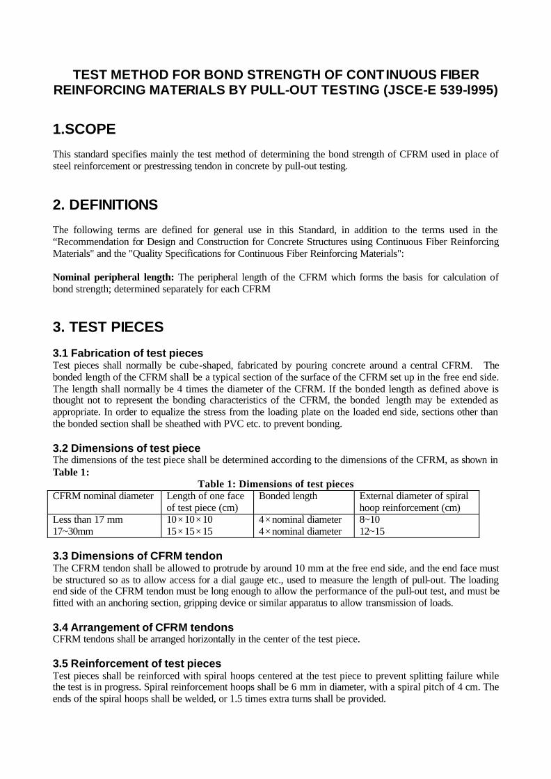
TEST METHOD FOR BOND STRENGTH OF CONTINUOUS FIBER REINFORCING MATERIALS BY PULL-OUT TESTING (JSCE-E 539-l995)
1.SCOPE This standard specifies mainly the test method of determining the bond strength of CFRM used in place of steel reinforcement or prestressing tendon in concrete by pull-out testing.
2. DEFINITIONS The following terms are defined for general use in this Standard, in addition to the terms used in the “Recommendation for Design and Construction for Concrete Structures using Continuous Fiber Reinforcing Materials" and the "Quality Specifications for Continuous Fiber Reinforcing Materials": Nominal peripheral length: The peripheral length of the CFRM which forms the basis for calculation of bond strength; determined separately for each CFRM
3. TEST PIECES 3.1 Fabrication of test pieces Test pieces shall normally be cube-shaped, fabricated by pouring concrete around a central CFRM. The bonded length of the CFRM shall be a typical section of the surface of the CFRM set up in the free end side. The length shall normally be 4 times the diameter of the CFRM. If the bonded length as defined above is thought not to represent the bonding characteristics of the CFRM, the bonded length may be extended as appropriate. In order to equalize the stress from the loading plate on the loaded end side, sections other than the bonded section shall be sheathed with PVC etc. to prevent bonding. 3.2 Dimensions of test piece The dimensions of the test piece shall be determined according to the dimensions of the CFRM, as shown in Table 1:
Table 1: Dimensions of test pieces CFRM nominal diameter Length of one face
of test piece (cm) Bonded length External diameter of spiral
hoop reinforcement (cm) Less than 17 mm 17~30mm
10× 10× 10 15× 15× 15
4× nominal diameter 4× nominal diameter
8~10 12~15
3.3 Dimensions of CFRM tendon The CFRM tendon shall be allowed to protrude by around 10 mm at the free end side, and the end face must be structured so as to allow access for a dial gauge etc., used to measure the length of pull-out. The loading end side of the CFRM tendon must be long enough to allow the performance of the pull-out test, and must be fitted with an anchoring section, gripping device or similar apparatus to allow transmission of loads. 3.4 Arrangement of CFRM tendons CFRM tendons shall be arranged horizontally in the center of the test piece. 3.5 Reinforcement of test pieces Test pieces shall be reinforced with spiral hoops centered at the test piece to prevent splitting failure while the test is in progress. Spiral reinforcement hoops shall be 6 mm in diameter, with a spiral pitch of 4 cm. The ends of the spiral hoops shall be welded, or 1.5 times extra turns shall be provided.

3.6 Number of test pieces The number of test pieces shall not be less than three. If the test piece is found clearly to have failed at the anchoring section, or to have slipped out of the anch6ring section, an additional test shall be performed on a separate test piece taken from the same lot.
4.FORMS Forms shall conform to the JSCE ”Test method for bond strength of concrete by pull-out testing" (JSCE-G 503-1988).
5. CONCRETE QUALITY The concrete shall be made with normal aggregates, with coarse aggregates having a maximum dimension of 20 or 25 mm. The standard concrete shall have slump of 10± 2 cm, and the compressive strength at 28 days shall be 30± 3 N/mm2.
6. PLACING OF CONCRETE 6.1 The bonding section of the CFRM tendon shall be cleaned and rendered free from any grease, dirt etc. 6.2 Suitable measures shall be taken before placing to prevent bonding of the non-bonding sections of the tendon, and the CFRM tendon shall be placed horizontally in the form, perpendicular to the loading face. 6.3 The opening in the form through which the CFRM tendon is inserted must be sealed to prevent ingress of water etc. using oil putty or similar. 6.4 The form must be kept horizontal from the time of placing the concrete until the form is removed. 6.5 After placing, the test piece shall be smoothed off by scraping any excess concrete off the top, repeating this process again after around 2 hours to ensure that a test piece of the proper dimensions is obtained.
7. REMOVAL OF FORMS AND CURING Forms shall be removed after 2 days, and the test pieces cured thereafter in water at a temperature of 20± 3 Co until the time of testing.
8. TESTING MACHINE AND DEVICES 8.1 Testing machine The testing machine for pull-out tests must be capable of applying the prescribed load accurately. 8.2 Loading plate The loading plate shall have a hole through which the CFRM tendon shall pass. The diameter of the hole in the loading plate shall be around 2~3 times the diameter of the continuous fiber tendon.

8.3 Anchorage The loading end side of the CFRM tendon shall be fitted with an anchorage capable of transmitting loads accurately until the tendon pulls out due to bond failure, or because of splitting or cracking of the concrete. The load transmission device shall transmit axial loads only to the CFRM tendon, without transmitting either torsion or flexural force. 8.4 Dial gauge The displacement meter fitted to the free end of the CFRM tendon shall be a dial gauge or similar apparatus, giving readings accurate to around 1/1000 mm.
9. TEST METHOD 9.1 Mounting of test piece The test piece shall be placed correctly on the loading plate, with a spherical plate underneath to prevent eccentric loads from acting on the test piece. 9.2 Loading rate The standard loading rate shall be such that the average tensile stress of the CFRM tendon increases at a rate of 10~20 N/mm2 per minute. The loading rate must be kept as constant as possible, not subjecting the test piece to shock. 9.3 Scope of test The slippage of the free end and the load applied shall be recorded in the increments shown in Table 2, until either the continuous fiber tendon pulls out of the concrete, or the load decreases significantly due to splitting or cracking of the concrete.
Table 2: Measurement increments Slippage of free end Measurement increment ~0.1 mm 0.1 mm~0.2mm 0.2mm~0.5mm 0.5 mm~
every 0.01 mm every 0.02. mm every 0.05 mm every 0.1 mm
9.4 Age of test piece The age of the test piece at the time of testing shall be 28 days.
10. CALCULATION AND EXPRESSION OF TEST RESULTS 10.1 Handling of data In cases where a test piece is judged to have undergone tensile failure at the anchoring section, or to have slipped out of the anchoring section before the CFRM has slipped from the concrete or the load is significantly reduced due to splitting or cracking of the concrete, the data shall be disregarded and additional tests shall be performed until the number of test pieces slipping from the concrete or where the load is significantly reduced due to splitting or cracking of the concrete is not less than three. 10.2 The bond strength shall be calculated according to Eq. (1) and rounded off to 3 significant digits and the curve for the pull-out load or bond stress versus slippage displacement for each test piece shall be plotted.

ulP
=τ (1)
where τ = bond stress (N/mm2) P = tensile load (N) u = nominal peripheral length of CFRM (mm) l = bonded length (mm)
10.3 The average bond stress causing slippage at the free end of 0.05 mm, 0.10 mm and 0.25 mm, and the maximum bond stress at the failure load shall be calculated.
11. TEST REPORT The test report shall include the following items: (1) Name of CFRM (2) Type of fiber and fiber binding material, volume ratio of fiber, type of surface treatment of fibers (3) Numbers or identification marks of test pieces (4) Designation, nominal diameter, nominal cross sectional area (5) Date of test, test temperature, loading rate (6) Dimensions of test pieces, bonded length of CFRM (7) Concrete mix, slump, and compressive strength at time of testing (8) Average bond stress causing slippage at the free end of 0.05 mm, 0.10 mm and 0.25 mm for each test piece (9) Maximum bond stress, failure mode and averages for each test piece (10) Bond stress - slippage displacement curve for each test piece

TEST METHOD FOR SHEAR PROPERTIES OF CONTINUOUS FIBER REINFORCING MATERIALS BY DOUBLE PLANE SHEAR
(JSCE-E540-1995)
1.SCOPE This specifications specifies mainly the test method for shear properties of CFRM used in place of steel reinforcement or prestressing tendon in concrete, by direct application of double shear.
2. TEST PIECES 2.1 Preparation of test pieces Test pieces shall as a rule not be subjected to any processing. For mesh-type CFRM, linear test pieces may be prepared by cutting away extraneous parts in such a way as not to affect the performance of the part to be tested. Test pieces should be as straight as possible; severely bent pieces should not be used. 2.2 Handling of test pieces During the obtaining and preparation of test pieces, all deformation, heating, outdoor exposure to ultraviolet light etc. causing changes to the material properties of the test section of the test piece must be avoided. 2.3 Length of test pieces Test pieces shall be of constant length regardless of the nominal diameter of the CFRM. Length shall not be less than 5 times the shear plane interval, and not more than 30 cm. 2.4 Number of test pieces The number of test pieces shall not be less than three. If the test piece shows significant pull-out of fibers, indicating that failure is not due to shear, an additional test shall be performed on a separate test piece taken from the same lot.
3, TESTING MACHINE AND DEVICES 3.1 Testing machine The testing machine to be used in load testing shall conform to JIS B 7733 (Compression Testing Machines). The testing machine shall have a loading capacity in excess of the tensile capacity of the test piece, and shall be capable of applying loading at the required loading rate. The testing machine must also be capable of giving readings of loading accurate to within 1% during the test. 3.2 Shear testing apparatus The shear testing apparatus shall be constructed so that a rod-shaped test piece is sheared on two planes more or less simultaneously by two blades (edges) converging along the faces perpendicular to the axial direction of the test piece. The discrepancy in the axial direction between the upper and lower blades shall be of the order of 0~0.5 mm, and shall be made as small as possible. The specifications distance between shear planes shall be 50 mm.

4. TEST TEMPERATURE The test temperature shall generally be within the range 5~35 Co . The specifications test temperature for test pieces sensitive to temperature shall be 20± 2 Co .
5. TEST METHOD 5.1 Mounting of test piece The test piece shall be mounted in the center of the shear apparatus, touching the upper loading device. No gap should be visible between the contact surface of the loading device and the test piece. 5.2 Loading rate The specifications loading rate shall be such that the shearing stress increases at a rate of 30~60 N/mm2 per minute. Loading shall be applied uniformly without subjecting the test piece to shock. 5.3 Scope of test Leading shall be continued until the test piece fails, and the failure load recorded to three significant digits. It should be noted that loading may decrease temporarily, owing to the presence of two rupture faces.
6. CALCULATION AND EXPRESSION OF TEST RESULTS 6.1 Handling of data Whether the rupture surface is due to shear or not shall be determined by visual inspection. If pull-out of fibers etc. is obvious, the data shall be disregarded and addit ional tests shall be performed until the number of test pieces failing due to shear is not less than three. 6.2 Shear strength Shear strength shall be calculated according to Eq. (1), and rounded off to 3 significant digits.
AP
2=τ (1)
where
τ = Shear strength (N/mm2) P = shear failure load (N) A = nominal cross sectional area of test piece (mm2)
7. TEST REPORT The test report shall include the following items: (1) Name of CFRM (2) Type of fiber and fiber binding material, volume ratio of fiber (3) Numbers or identification marks of test pieces (4) Designation, nominal diameter, maximum cross sectional area (5) Date of test, test temperature, loading rate (6) Intervals between double shear faces (7) Shear failure load for each test piece, average shear failure load and shear strength (8) Failure mode of each test piece
![‘Butterfly acoustical skin’ – new method of reducing aero ......cated later ructures (lo light [26] average siz These struc. location. T verage ins th bending ies [20], Z of](https://img.pdfslide.us/doc/110x75/5f4daa6b4eb04076b311057f/abutterfly-acoustical-skina-a-new-method-of-reducing-aero-cated-later.jpg)