Embed Size (px)
Citation preview
CEWELL, ONGC, Baroda-39009,
10th Biennial International Conference & Exposition
P 042
Recognizing Horizontal Stress Orientation for Optimizing Well Placement
and Well Completion Jobs
R.R. Tiwari
Summary
Knowledge of horizontal stress orientation can be utilized for addressing issues related to wellbore stability in any fault
regime. Inclined wells drilled in the direction of minimum horizontal stress tend to be more stable in a normally
faulted basin compared to those drilled in any other directions. Further, they also have the advantage of cutting
through the natural fractures as these fractures tend to align themselves with the direction of maximum horizontal
stress. On the contrary, inclined and horizontal wells drilled in the direction of maximum horizontal stress are likely to be
more stable in a strike-slip fault regime or thrust fault regime. Well stimulation jobs like hydro- fracturing are
preferred in the direction of maximum horizontal stress as all the induced fractures eventually tend to align themselves
in this direction and fracturing in other directions will unnecessarily increase the tortuosity. Likewise, in
unconsolidated sand reservoirs, initiation of sanding starts in the direction of minimum horizontal stress and hence if the
perforations are carried out in the direction of maximum horizontal stress only (oriented perforation), the problem can
be postponed for some time. We can therefore say that knowledge of the orientation of horizontal stresses is not
only important for well planning, it is equally important for well completion.
The direction of horizontal stresses can be located with the help of some of the logging tools like 4-arm caliper, formation
imaging tool and dipole shear sonic tool recorded in cross-dipole mode. In this paper we propose to exhibit all these
methods to firm up the direction of horizontal stresses in a couple of fields operated by ONGC so that future strategy
regarding the trajectories of upcoming wells can be drawn. The information will be also useful when well stimulation
activity like hydro-fracturing is considered.
Keywords: Importance of Horizontal Stress Orientation
Introduction
Earth is a stressful place and the sub-surface too is equally
stressful. The weight of the ever-depositing
sediments increases the over-burden and since the rocks
are not allowed to expand laterally because of
confinement, there arises a strain in lateral direction
which gives rise to horizontal stresses. If there is no
post-deposition tectonic activity in the basin, the over-
burden is the only reason for the horizontal stresses and the
basin is known as normally faulted. However, if there
occurs some post-depositional tectonic activity in the
basin, a tectonic factor will get added to the horizontal
stresses and depending on how big is this factor, the
basin may either undergo strike-slip faulting or reverse
faulting. In both the cases the compressional force
is large enough to exceed the over- burden. If the
overburden happens to be the intermediate stress and
the maximum and the minimum horizontal stresses
are the largest and the smallest respectively then the
fault system will be strike-slip and if both the horizontal
stresses surpass the overburden then the fault system
will be reverse or thrust.
Before undertaking any drilling activity in any area it
is prudent to know the prevalent fault system as well as
the magnitude and direction of stress tensors. For example,
in a normally faulted basin a vertical well requires the least
mud weight from wellbore stability point of view whereas
in a strike-slip or reversed fault regime an inclined or
horizontal well in a preferred direction will have the least
mud weight requirement. Further, the knowledge of the
magnitude of these stresses enables us to estimate the hoop
stress acting on the periphery of the wellbore so that

2
one can predict whether the rock with a given strength
and given mud weight will fail or not. Besides magnitude,
the direction of horizontal stresses becomes all the more
important when we plan to drill deviated and horizontal
wells. In a normally faulted basin, the preferred well
azimuth is the orientation of minimum horizontal stress
whereas in strike-slip or thrust fault basin the preferred
direction is that of maximum horizontal stress. In this work
we will limit our study to the direction of horizontal
stresses.
In cases of stress related anisotropy if the rock is not drilled
with appropriate mud weight, breakouts starts appearing in
the direction of minimum horizontal stress direction where
the compressive hoop stress is maximum. We can also see
drilling induced fractures in the maximum horizontal stress
direction in which case the hoop stress becomes
negative and the rock fails in tension. Both these
phenomenon can be very well seen on an image log. The
directions of these activities can also be located on the
image log as these tools are always run with inbuilt
navigational package. A simple 4-arm caliper with
navigational tool can also indicate breakouts leading
to the direction of minimum horizontal stress. These
breakouts and drilling induced fractures may not, however,
appear in all circumstances and depending on the used mud
weight, differential stress magnitude and the rock strength,
they may fail to appear on the image log or caliper log even
though the stress anisotropy exists. In that case shear sonic
recoded in cross-dipole mode is the most trusted way to
know the direction. Even the nature of anisotropy (whether
due to fracture network or stress difference or thin bed
laminations) can also be established with this tool with the
help of frequency dispersion plots. The processed data
from the tool gives the fast shear azimuth which in case of
stress anisotropy is nothing but the maximum horizontal
stress azimuth.
Method & Examples
We will now elaborate the ways discussed above with
suitable examples from fields operated by ONGC.
1. Breakouts and Drilling Induced Fractures on Image
Logs:
Image logs like UBI or FMI or STAR can be recorded to
see breakouts or drilling induced fractures. The breakouts
are seen as conductive out of focus zones on the image logs
as depicted in Fig-1. They appear on the opposite pads
which are 180 deg apart. As the azimuth of Pad1 (reference
pad) is known, the orientation of the breakout can be
established. The direction of breakouts in this figure is
50/230 deg, which also is the direction of minimum
horizontal stress.
Fig-1: Breakouts on resistivity image log
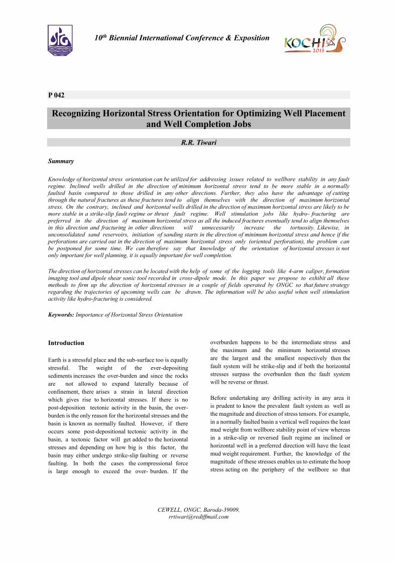
In vertical wells, drilling induced fractures appear as
vertical dark lines on two opposite pads, as shown in Fig-
2. These fractures remain confined to wellbore wall only.
Natural fractures can be distinguished from induced
fractures keeping in mind that natural fractures appear on
all the pads as a sinusoid whereas induced fractures appear
only on two opposite pads. Like in case of breakouts, the
direction of drilling induced fractures can also be
established with the knowledge of Pad1 azimuth. The
direction of drilling induced fractures in this case is
140/320 deg, which is the direction of maximum
horizontal stress. It may be noted here that since both
breakouts and drilling induced fractures have been picked
up here from the same well, the difference in their
orientation is 90 deg.
3
Fig-2: Drilling induced tensile fracture on image log
2. Breakouts on 4-arm caliper:
If we record two calipers in directions orthogonal to each
other and if one caliper reads bit size whereas the second
one reads more than the bit size then this event can be
termed as a breakout provided the following conditions are
broadly met:
• The tool rotation should stop in the breakout
zone (can be checked from Pad1 azimuth curve or
relative bearing curve). This is because the larger
caliper falls in the breakout groove and does not
allow the tool to rotate. If however the tool motion
is not arrested then it may be a hole enlargement
(washout) or key-seat, and not necessarily a
breakout.
• The smaller caliper should be larger than or
equal to the bit size. If it is larger, then it should not
exceed 1.1 times the bit size.
• If the smaller caliper is larger than bit size
(within the above prescribed limit), it should show
less variations than the larger caliper.
• Both the calipers should be at least 5% different
from each other.
• Length of breakout zone should be larger than at
least half a meter.
Keeping these conditions in mind the breakout zones can
be picked up from the caliper log (Fig-3) and its azimuth
Fig-3: Breakout analysis from 4-arm caliper
can be plotted as a rose plot (Fig-4). As can be seen in Fig3,
the tool rotation is arrested in the breakout zones (Pad1
azimuth is constant) in the bottom and top section. This
example is from deep-water Andaman block where the
minimum stress direction is established as N-S on the basis
of breakout analysis (Fig-4).

4
Fig-4: Rose plot for azimuth
Another example (Fig-5) is from a Mumbai Offshore field
where the minimum stress direction is seen as 138 deg on
the caliper breakout.
Fig-5: Breakouts seen on 4-arm caliper log
3. Fast shear azimuth from shear sonic in cross-dipole
mode:
Tools like XMAC, DSI or Sonic Scanner respond to stress
anisotropy if recorded in cross-dipole mode. When a
polarized shear wave (generated by these tools) travels in
an anisotropic medium, it splits into two polarized waves
(also known as seismic birefringence). One of these waves
is faster than the other and oriented parallel to the fractures
or cracks if the anisotropy is caused due to presence of
fracture network. If, however, the anisotropy is caused due
to horizontal stresses, the fast shear wave will be polarized
in the direction of maximum horizontal stress. It is may be
noted here that in the common tool configuration where the
tool axis is vertical and the beds are horizontal (zero dip),
anisotropy due to thin beds or due to sand facies will not
be picked by the tool. Hence in a vertical well with gentle
bed dip the tool will either respond to stress anisotropy or
anisotropy due to the presence of fracture network.
In the example shown here (Fig-6) from Mumbai offshore,
the presence of any fracture network is ruled out, as the
image log of this well does not indicate any. Therefore the
anisotropy present in this case is due to horizontal stress
differential and the fast shear azimuth is essentially the
azimuth of maximum horizontal stress. The azimuth in this
case is 320 deg.
Fig-6: Shear log in cross-dipole mode showing anisotropy
and fast shear azimuth

5
Conclusion
As horizontal stress orientation is an important parameter
for trouble-free well placement, optimum hydro-fracturing
jobs and sand avoidance completions with oriented
perforations, a precise measurement of the same can be
successfully achieved through logs like 4-arm caliper,
resistivity or ultrasonic images and shear sonic recorded in
cross-dipole mode. Such measurements can be planned in
the appraisal or offset wells so that the information can be
used during the development phase of the field.
References
Using drilling and logging data for developing 1D MEM
for a mature field by M Afsari et.al. SPE paper 132187
Advanced application of borehole images and acoustic
logs in building robust geo-mechanical model for
TaptiDaman field by Rajeev Kumar, et.al, SPE paper
154589
Determination of stress orientation and magnitude in deep
wells by Zoback M D et.al, Int J Rock Mech & Mining Sci
40 (2003): 1049-76
Using borehole breakout to constrain complete stress
tensor by Blair J Z et.al, Journal of Geophysical research,
Vol:102, No.B5, Pages 10083-100, May 1997
Insitu stress orientation and magnitude at Fenton
geothermal site determined from wellbore breakouts by
Barton C A et.al, Geophys Res Lett, 15(5), 467-70
Utilizing wellbore image data to determine the complete
stress tensor: Application to permeability anisotropy and
wellbore stability Barton C A et.al, The Log Analyst, pp.
21–33
Constraining the full stress tensor from observations of
drilling-induced tensile fractures and leak-off tests:
Application to borehole stability and sand production on
the Norwegian margin by Wiprut D et.al, Intl. J. Rock
Mech. & Min. Sci., v.34, no.3–4, Paper No. 00365