Embed Size (px)
Citation preview
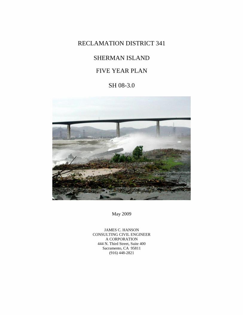
RECLAMATION DISTRICT 341
SHERMAN ISLAND
FIVE YEAR PLAN
SH 08-3.0
May 2009
JAMES C. HANSON
CONSULTING CIVIL ENGINEER
A CORPORATION
444 N. Third Street, Suite 400 Sacramento, CA 95811
(916) 448-2821

2
TABLE OF CONTENTS
Chapters:
1. Executive Summary…….……….……………………………………….……… 4
2. Brief History of Sherman Island……………………………………………........ 6
3. An Inventory of Assets Protected by the Sherman Island Levee System………. 9
4. Consequences of Levee Failure or Breach……………………………………… 13
5. Future Goals for the Sherman Island Levee System…………………………….. 18
6. Assessment of the Existing Sherman Island Levee System……………...……... 19
7. Data Collection and Monitoring………………………………………...………. 21
8. Identification of Opportunities for Multi Objective Projects……………………. 26
9. Proposed Work to Reduce Island‟s Vulnerability to Failure……………………. 28
Exhibits:
Sherman Island Location and Vicinity Map……………………………… Exhibit A
Strategy to Meet the Desired Level of Protection…..…………………….. Exhibit B
Appendices:
Five Year Plan Requirements…………….…………………………......Appendix A
Available Data………………………………………….…………...…...Appendix B
Levee Crest Elevation Survey……………………………. ………...…..Appendix C
Bathymetric Data………………………………………………………..Appendix D
Electromagnetic Anomaly Data…………………………………………Appendix E
Visual Survey Data…………………………………………………..… Appendix F
Available Technical Reports…………………………………………… Appendix G

3
TABLE OF CONTENTS CONT.
Emergency Response Plan……………………………………...……… Appendix H
2001 Department of Fish and Game Habitat Assessment……………….Appendix I
CALFED Study………………………………………………………… Appendix J
Sherman Island Fault Map………………………………………………Appendix K
Intake facilities, Drainage Canal and Discharge Station………………...Appendix L

4
1. Executive Summary
The Five Year Plan (Plan) has been defined in the Delta Levee Special Flood Control
Projects Final Interim Guidelines for Providing Funding to Local Public Agencies
(Interim Guidelines) as a document that describes, in detail, a District‟s integrated work
plan to repair and improve flood protection infrastructure for the next five years. The
requirements of the Plan are set forth in Attachment A of the Interim Guidelines (see
Appendix A) and include:
assessment of the status of existing levee systems and future goals,
strategy to meet desired level of protection,
identification of need for improvements to alleviate or minimize existing hazards,
identification of the risks for current land use based on the existing assets,
identification of opportunities for multi-objective project,
habitat mitigation and enhancement and
compliance with CEQA and obtaining required permits.
The contents of the Plan are based on both the requirements included in the Interim
Guidelines and on direction received from Department of Water Resources staff. In
accordance with staff direction, this Plan contains a detailed accounting of all technical
information available. The information is presented and analyzed for the purpose of
determining potential levee stability issues. Stability issues are reviewed with regard to
the District‟s five year level of protection goal, and projects to enhance stability or to
gather additional technical information as required are proposed in order of priority.
The objective of the Five Year Plan is to identify improvement projects to the Sherman
Island levee system that will protect public facilities and provide public benefits for a five
year period. Improved levees minimize the threat of levee failure, protect Delta water
quality and protect the reliability of the State Water Project, Contra Costa Canal, and
Central Valley Project, and other local and non-local assets.
The Five Year Plan provides a strategic approach to rehabilitation of the levees and
identifies habitat mitigation possibilities to facilitate implementation of the levee
improvement projects. It is intended that with the Plan in place, feasible projects will be
identified and ready to implement as funding becomes available.

6
2. A Brief History of Sherman Island
Geomorphic Evolution
The geomorphology of the Sacramento-San Joaquin Delta before the period of Euro-
American colonization was dominated by intertidal landscapes shaped by sea-level rise
and sedimentation. During the last glacial period, around 15,000 years ago, relative sea
level was approximately 300 ft lower than today and the Pacific coast was at least 6 miles
west of its present position. During this time the Delta formed part of the arid alluvial
floodplain of the Central Valley and alluvial sand deposits together with aeolian sand
deposits underlie most of the late Holocene Delta soils.
Between 10,000 and 5,000 years ago relative sea-level rise was rapid, approximately 6
mm/yr, then about 5,000 years ago the rate slowed to about 1-2mm/yr. At this time sea
water encroached landward through the Carquinez Strait into the lowlands that became
Suisun Bay and the Delta. It is likely that early in the formation of the Delta landscape
(6,000 to 5,000 years ago), the rate of relative sea-level rise created more accommodation
space than could be filled by the flood-borne sediment supply, and brackish sedimentary
environments transgressed landward. This period of time saw the widespread deposition
of organic silt and clay across the alluvial floodplain surface.
The Sacramento Delta to the north comprised about 30% of the total historic Delta area
and extended as far as Sherman Island to the west. Its morphology was created by the
interaction of rising sea level, alluvial river-flood deposition and tidal marsh peat
formation. This created an inland „bird‟s foot delta‟ of distributary channels bordered by
higher supratidal natural levees, and surrounded by marsh plains.
In the Delta, for the last 5,000 years to the 1850s, relative sea-level rise was balanced by
vertical marsh growth through biomass accumulation and sediment deposition. A
transition from deposition of organic silt-clay to peat formation in the Delta largely
reflects the decline in inundation frequency and the maturation of the marsh plain
towards mean higher high water elevations. The resulting freshwater tidal marshes
developed because a relatively large freshwater inflow compared to the size of the tidal
prism sustained a low salinity, which supported highly productive organic peat formation
through tule growth. The large roots of the tule created an organic fabric that supported
and aided rapid vertical growth. The living surface was maintained within the intertidal
zone (natural habitat), and marsh organic accretion (injection of roots and rhizomes, and
incorporation of surface litter) was able to sustain vertical growth at rates in excess of
relative sea-level rise. The gradual accumulation of the organic and inorganic sediment
must have also offset the loss and compaction of existing peat.
The development of today‟s Delta began in late 1850 when the Swamp and Overflow
Land Act conveyed ownership of tall swamp and overflow land, including Delta marshes
from the federal government to the State of California. Reclamation of Sherman Island
began shortly thereafter, and by 1859, local property owners had constructed small peat
7
levees of three to four feet in height, with a base width of about eight feet, along the
banks of the Sacramento River and Mayberry Slough.
Historical Flood Events
The first significant flooding affecting Sherman Island agriculture occurred during the
1861/62 season and caused wide-spread damage throughout the delta‟s river islands, and
Sherman Island farmers lost most of their livestock as a result when the Sacramento
River breached the low levees constructed along its banks. After completion of the levee
system in 1869, Sherman Island suffered several floods. Sherman Island levees failed
during the winters of 1871/72, 1874/75, 1876, and 1878. Several crevasses cut through
the north and south levees west of Mayberry Slough in the 1874 levee failure, resulting in
the loss of all but 100 acres of cropland in the western portion of the island. The
subsequent levee reconstruction featured a 12-foot high peat levee with 120 feet widths at
the base. Even so, the 1876 flood covered the western portion of the island again. The
flood of 1878 devastated the entire island.
Subsequent levee breaks on the San Joaquin River submerged most of the land and
Sherman Island‟s 700 inhabitants fled to higher ground. The beleaguered reclamation
districts were faced with underwriting thousands of dollars in assessments to replace most
of the levee system. Landowners regrouped, and in March 1878, Reclamation District
252 formed out of a portion of RD 54. Sherman Island landowners reorganized again, and
RD 54 and RD 252 combined to form Reclamation District No. 341 (RD 341) on June
17, 1879. Although reclamation efforts continued in RD 50 west of Mayberry Slough for
several years after the 1879 floods, landowners eventually dropped reclamation efforts,
and after the land flooded during the 1940s, ownership of the land reverted to the State
for taxes.
By spring 1880, most of the new RD 341 was again under cultivation until high waters
collapsed levee sections again in August later that year. Although an assessment of
$13,141 was made for levee repair following the 1880 break, most of the land remained
under water until 1894 when reclamation efforts were renewed.
In 1894, RD 341 encompassed 10,303.71 acres of land east of Mayberry Slough and the
3,000-foot cross-levee between Sacramento River and Mayberry Slough. The Sacramento
and San Joaquin rivers are connected by Three Mile Slough, which forms the eastern and
northern boundary of the Island. The district included 24.76 miles of levee, much of it at
the time destroyed by previous floods. At the time, much of Sherman Island had been
underwater for fifteen years. Although some stretches of levee were intact, much of the
levee had had sunk to the ground level of the island or below. The Horse Shoe Bend area
of the Sacramento River had several breaks; one about 500 feet in width, with resulting
scar holes measuring about 75 feet deep. The San Joaquin River levees on the south side
of the island were essentially destroyed from Gallagher Slough, near the modern day
location of Eddo‟s Resort, to the mouth of Mayberry Slough.
During the first decade of the twentieth century, RD 341 conducted frequent levee
upgrading and restoration projects on Sherman Island. RD 341 leased four dredges in

8
1900 that worked in tandem around Sherman Island. Flooding occurred in some section
of the Delta almost annually during the period from 1900 to 1910, and serious levee
breaks and major flooding of RD 341 occurred during 1904 when a crevasse opened on
Mayberry Slough, and in 1906 and 1909, when water again inundated the island. RD 341
trustees contracted with Franks Dredging Company for levee construction and repair
work between 1908 and 1920.
The southern levee on the San Joaquin River side failed and flooded the Island on
January 20, 1969 at approximate levee station 520+00. Upon finding the break, a large
quantity of rock was placed on the upstream and downstream ends of the levee to protect
against further erosion from high velocities into and out of the break due to tide. Without
placement of the rock, the break which was approximately 275 feet wide and about 45
feet below mean sea level, would have been greatly enlarged. After the break, the water
inside the island and in the San Joaquin River was at the same level. The flooding
created a deep hole in the channel on the waterside and a deep lake on the landside toe of
the levee at the site of the break. Pumps to dewater the Island were rented (District
pumps were entirely submerged). Pumping with the rented equipment commenced
February 28, 1969 and continued through August 9, 1969, at which point District pumps
continued to remove the remaining water from the Island. All 93,000 feet of District
drainage ditches were cleaned and/or excavated, primarily by drag line and ditcher
operations before District ditches were operable. The Corps of Engineers spent
approximately $600,000 in emergency funds to repair, reslope, and regrade the levee
break area after the 1969 break. Seepage and settlement in the area of the break have
been ongoing issues requiring constant levee improvements.
Photograph from July, 2008 of the Scour Pond created by the 1969 breach.
9
3. An Inventory of Assets Protected By the Sherman Island Levee System
Sherman Island Today
Today, Sherman Island (see Exhibit A) is protected by approximately 18-miles of levee
which encompass approximately 9,937 acres of land, according to the 1995 Sacramento
Delta San Joaquin Atlas. Approximately 9 miles of levee are project levee, constructed
by the US Army Corps of Engineers, and approximately 9 miles of levee are non-project
levee. The entire levee system is maintained by RD 341. RD 341 maintains and operates
five modern pumping stations on Sherman Island: three on the San Joaquin River (south)
side; one on the Sacramento River (north) side; and one on Sherman Island‟s northwest
corner. The pumps are part of a larger system of pumps, siphons irrigation ditches and
canals used to circulate water and drain the Island. See Appendix L for details of the
drainage system including location of the canals, siphons and pumps. Also included are
pump capacities. Irrigation and canal ditch capacities are not available at this time.
According to the 2000 census, the Island has a population of 233 people, with 110
dwelling units. The District maintains an emergency response plan in the event a
dangerous condition could significantly compromise the levee system (see Appendix H).
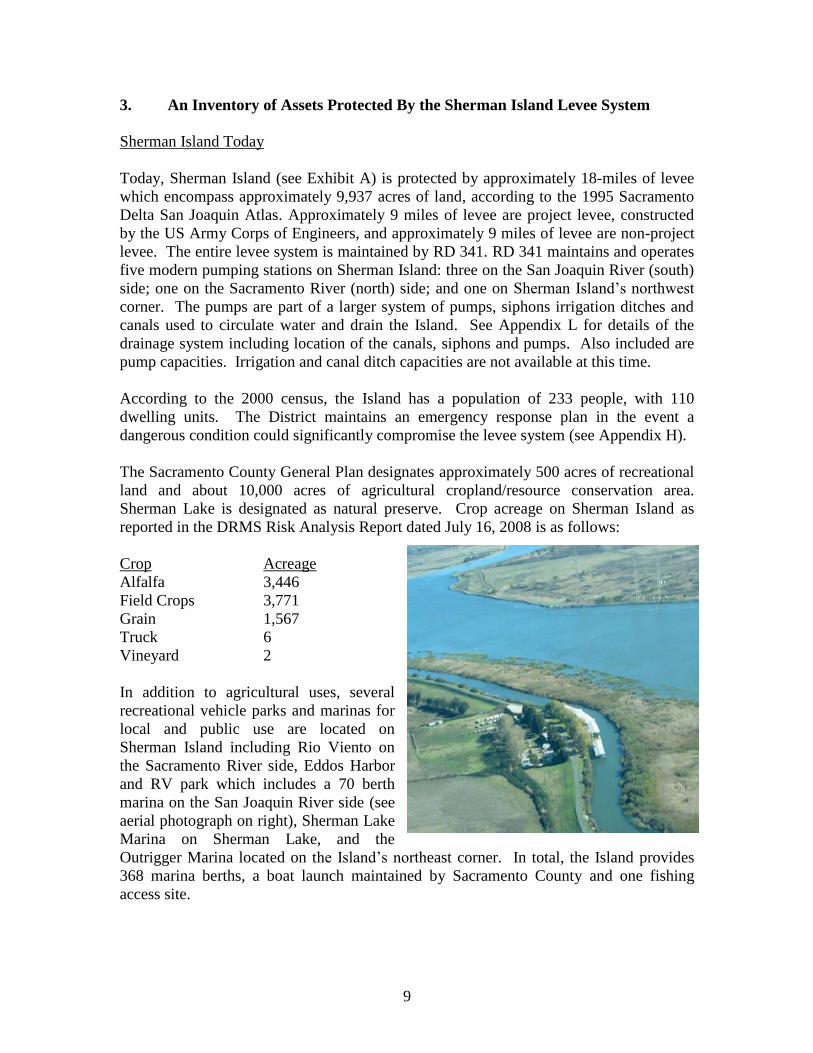
The Sacramento County General Plan designates approximately 500 acres of recreational
land and about 10,000 acres of agricultural cropland/resource conservation area.
Sherman Lake is designated as natural preserve. Crop acreage on Sherman Island as
reported in the DRMS Risk Analysis Report dated July 16, 2008 is as follows:
Crop Acreage
Alfalfa 3,446
Field Crops 3,771
Grain 1,567
Truck 6
Vineyard 2
In addition to agricultural uses, several
recreational vehicle parks and marinas for
local and public use are located on
Sherman Island including Rio Viento on
the Sacramento River side, Eddos Harbor
and RV park which includes a 70 berth
marina on the San Joaquin River side (see
aerial photograph on right), Sherman Lake
Marina on Sherman Lake, and the
Outrigger Marina located on the Island‟s northeast corner. In total, the Island provides
368 marina berths, a boat launch maintained by Sacramento County and one fishing
access site.

10
Local Assets
The DRMS July 16, 2008 Risk Analysis Report indicates that the Sherman Island levee
system protects approximately $11,500,000 in local assets. The following table provides
a breakdown of local assets for which the District can levy assessments:
Land Use Acres
Agricultural 6,132.83
Agricultural-Irrigated from District Facilities 4,003.44
Marina-Recreation 14.98
Urban 79.51
Commercial 7.52
Utilities 0.75
10,239.03
Utility Easements
Rosetta Resources Corporation 8.69
Pacific Gas and Electric Co. 414.23
Great Western Power Co. 46.39
Natural Gas Corporation of Calif. 4.70
Lodi Natural Gas and Storage 12.81
Western Area Power Administration (WAPA) 83.54
557.55
The local assets described above include recreational facilities, easements for
infrastructure and local infrastructure. Sherman Island Levee Road, a ten to fifteen foot
wide road both paved and graveled, runs on the levee crown. The road provides access to
the recreational vehicle parks and marinas for local and public use, fishing area and
windsurfing area.
Although the assets listed above are local assets against which the District can levee
assessment for flood protection, the levees also protect non-local assets which provide a
public benefit.
11
Non-local Assets and Public Benefit
The Sherman Island levee system protects non-local assets which provide a public
benefit, including infrastructure, utilities, water quality and water supply reliability.
Below is a list of the non-local assets protected by the levee system:
Non-local Assets Protected by the Sherman Island Levee System
Water Delivery System*
State Water Project
South Bay Aqueduct
North Bay Aqueduct
Federal Central Valley Water Project
Delta Mendota Canal
California Aqueduct
Contra Costa Canal
Miscellaneous Diversions Directly from the Delta
Western Delta Industry
1800+ Agricultural Diverters
City of Vallejo diversion
Infrastructure
State Route 160
Highway 160 Drawbridge
Dam (forms Mayberry Canal)
Utilities
Major 500kV Transmission Lines
WAPA California Oregon Transmission Project
PG&E Table Mountain-Tesla line
PG&E Vaca Dixon-Tesla line
Natural Gas Resources
Natural gas pipeline from Canada
Natural gas storage area
Telecommunication and fiber optic lines
Note:
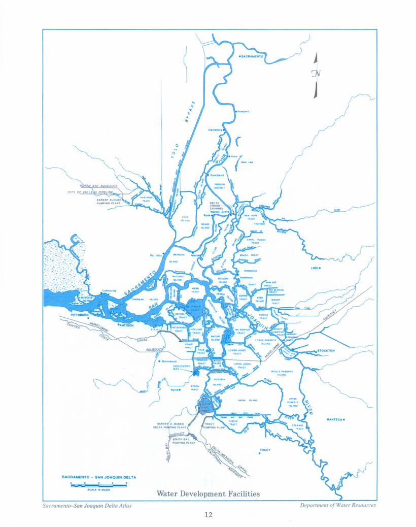
See following diagram of Water Development Facilities

13
4. Consequences of Levee Failure or Breach
Consequences of Sherman Island levee failure or breach for local and non-local assets
described in the previous chapter are described briefly below. For a more comprehensive
discussion of risk and possible consequences of asset loss, see The Risk Analysis Report
dated July 16, 2008 completed as part of the Delta Risk Management Strategy (DRMS).
The DRMS report provides detailed descriptions of types of failures possible and
economic consequences of such failures.
In addition to the costs incurred to repair or replace the assets destroyed by Sherman
Island levee failure, an immediate cost would be pumping out the Island. To estimate the
cost of restoring Sherman Island, we considered the 2004 failure of the Upper Jones
Tract, an Island of 6,259 acres which cost approximately $120 million to restore. This
equates to about $19,100 per acre, and assuming inflation of 4% a year, would be about
$22,200 in 2009. Accordingly it would cost approximately $221 million to pump out and
restore Sherman Island (9,937 acres X $22,200 per/acre = $221 million). This estimate is
conservative in that it does not account for the elevations on the interior of Sherman
Island, which are up to 20 feet below sea level. Sherman will likely impound a greater
volume of water per acre than Upper Jones Tract, and per acre restoration costs will
therefore be greater.
Transmission Lines
Three major electric transmission lines (greater then 500kV) cross Sherman Island: the
California Oregon Transmission Project, operated by the Western Area Power
Administration, the Pacific Gas and Electric Company (PG&E) Table Mountain-Tesla
line, and the PG&E Vaca-Dixon-Tesla line. These lines work mainly to interconnect
California loads and generation with loads and generation in the Pacific Northwest. The
three lines through the Delta are operated as a coordinated grouping, with maximum
imports or exports limited to provide some joint redundancy to help ensure reliability.
The combined load on these three lines is typically around 4,000 MW, though under
some circumstances it can be as high as 4,800 MW (Mirzadeh 2006). This is
approximately ten percent of statewide summer loads, which is less than the required
planning reserve margin of 15 percent. However, other outages may occur at the same
time as this disruption, so under some circumstances the loss of all three lines due to the
failure of the Sherman Island levee system could cause operating problems.
PG&E also operates two other lines with less than 500kV capacity to provide local
service to Sherman Island and nearby Delta Islands. Failure of the Sherman Island levee
system would impact the ability of PG&E to serve the local delta community.
The DRMS report estimates the cost of a two month outage of two 500 kV lines to be
$42,000,000. For additional information, please refer to the DRMS report.

14
The photograph to the right shows
the major and local transmission
lines described above.
Natural Gas Resources
Sherman Island has 60
natural gas and oil wells, and
approximately 1,082 acres of
gas and oil production fields.
In addition, the levees protect
145,514 feet of a natural gas
pipeline which originates in
Canada and crosses Sherman
Island. Failure of the
Sherman Island levee system
would interrupt gas service
through the pipeline and gas production and storage occurring on Sherman Island.
IMPACTS TO WATER QUALITY
Sherman Island levees provide a public benefit by maintaining water quality and water
supply reliability for cities and farms in the San Francisco Bay area, San Joaquin Valley,
and Southern California. Sherman Island is situated where fresh river water and salty bay
water meet and mix. Under typical summer salinity conditions in the lower Sacramento
River, salinity rises sharply in the area of Sherman Island. Consequently, the island‟s
levees are critical to controlling salinity intrusion to the interior Delta. A levee break
would increase the rate and area of mixing and would allow the saline bay water to move
further upstream, jeopardizing the fresh water supply taken from the Delta for the Central
Valley Project water supply, the State Water Project and the Contra Costa intake (see
previous Water Development Facilities diagram).
An artificial balance is maintained in the water exchanged between the Delta and the San
Francisco Bay. Freshwater inflows regulated by upstream dams and diversions supply
water to the Delta ecosystems and to farms and cities in central and southern California.
Failure of Sherman Island levees would tip the water exchange balance in favor of more
saltwater intrusion, which can ruin the water for agriculture and domestic uses supplied
by the State Water Project and the Central Valley Water Project. Any reductions in the
supply of imported Delta water could force water purveyors in many parts of the State to
meet water demand with ground-water supplies. This, in turn, could renew land
subsidence in the Santa Clara and San Joaquin Valleys and exacerbate subsidence in
Antelope Valley and other areas that currently are reliant on imported Delta water
supplies and prone to aquifer-system compaction.
The presence of the western Delta islands, Sherman Island in particular, is believed to
effectively inhibit the inland migration of the salinity interface between the Bay and
Delta. If Sherman Island were to become permanently inundated with saline water, the

15
water available to the massive pumping facilities near the Clifton Court Forebay might
become too saline to use. The timing of levee breaks and flooding is critical in this
regard. Fortunately, most flooding occurs in winter and spring, when major saltwater
intrusion is less likely. However, there are occasional levee failures under low-flow
conditions. These failures can cause major short-term water-quality problems, even if the
flooded areas are later reclaimed. During one such incident, which occurred in summer of
1972, the Andrus Island levee failed, flooding an area slightly larger than Sherman
Island. Salt concentrations in the central and western Delta quickly showed an increase
up to sixfold. It took a large volume of extra reservoir releases to flush the salty water
from the west Delta. The Andrus Island levee break may also have been a contributing
factor in high mortality of juvenile bass that year. Similar impact could occur if one of
Sherman Island‟s levees were to fail under low flow conditions.
The Department of Water Resources modeled salinity impacts of levee breaches in the
Delta with the DWR Delta Simulation Model 1 (DWRSIM1). In particular, DWR
modeled the long-term impacts of un-repaired levees. DWRSIM1 accounted for Delta
bathymetry, tidal fluctuations, facility configurations, water exports, breach size, and
location. The model predicted altered salinity levels and compared them to historical
salinity levels over four years at eight locations in the Delta (DWR, 1999). DWR
concluded that un-repaired levee breaches on Sherman Island would nearly double
salinity near the Contra Costa Water District intakes.
Reducing increased salinity levels hinges on repairing the levee breaks, flushing the Delta
with upstream reservoir releases, and pumping out salt water in the south Delta (DWR,
1982). Failure to repair the levees in a timely manner not only perpetuates elevated
salinity levels in the Delta but also increases the damage to remaining portions of the
levee systems. While the islands are inundated, the interior face of the levee is subject to
wind generated wave erosion. The combination of several large levee breaches and waves
rapidly eroding the levees from the interior increases the amount of time and material
necessary to repair the levees, and subsequently, the amount of time to reduce salinity
levels to acceptable levels. If emergency response teams are unable to repair all the levee
breaches and pump water off the islands, it is conceivable that salinity levels will remain
elevated and terminate an entire year or more of water exports. If a levee were to break
and not be repaired, the situation would continue, resulting in long-term degradation of
Delta water quality that would adversely affect several beneficial uses, including fish and
wildlife, municipal and industrial, and agricultural uses. The situation would be
especially severe on Sherman Island because of the Island‟s size (9,900 acres) and
interior elevation, which is in excess of 20 feet below sea level.
The quality of water supplies derived from the Delta depends to a great extent on the path
the water takes through the Delta to the export facilities. Water diverted from the
Sacramento River upstream of Sherman Island and transported through the Delta
waterway to the Delta export facilities maintains good water quality because mixing with
saline water from the ocean is minimal or non-existent. Water that takes a reverse flow
path around the western end of Sherman Island is of poorer quality because it is forced to
blend with ocean-derived water high in chlorides. Increased chloride levels affect the

16
ability of water project operators to meet Delta water quality standards. Permanent
flooding of Sherman Island would worsen this situation resulting in even higher chloride
concentrations. This would require modifications in project operations involving releases
of upstream storage to help offset the chloride levels.
The water supply relied upon by the Central Valley Water Project, State Water Project
and miscellaneous diversions directly from the Delta, and the regions they serve would be
negatively impacted should water quality fall below acceptable standards due to a salinity
increase caused by failure of Sherman Island levees. Projections of increased salinity
resulting from a levee breach are included in Appendix J.
The DRMS report provides an estimate of the cost to urban water uses which would
result from a water shortage, such as that which could be caused by a decrease in water
quality due to failure of the Sherman Island levee system. The estimate ranges from
$23,000,000 million per month assuming a 5% shortage in water deliveries to
$81,938,000,000 per month, assuming a 100% disruption in water supply. For additional
information, please refer to the DRMS report.
STATE INFRASTRUCTURE
Sherman Island levees also protect State Highway 160 and the drawbridge at Three Mile
Slough. State Route 160 connects Sherman Island to the mainland Sacramento County
on the northeast corner via Threemile Slough Bridge (Bridge 24-0121), and to Contra
Costa County on the island‟s west side, via the Antioch Bridge (Bridge 28-0009). Failure
of the Sherman Island levee system and resulting loss of State Route 160 and access to
the Antioch Bridge would severely impact truck and vehicular traffic relying on this
roadway. To determine the reduction in public benefit which would be realized should
the levees fail, we reviewed Annual Average Daily Traffic (AADT) counts and Annual
Average Daily Truck counts available from Caltrans. AADT is the total volume of traffic
from October 1st through September 30th
divided by 365 days. The results are shown on
the table below:
State Route 160 Traffic Counts
SR 160 Count Location AADT Truck AADT
Back* Ahead* Back* Ahead*
Antioch, Junction Rte. 4 east N/A 12,800 1,678
Wilbur Avenue 12,800 14,900 971
Contra Costa/Sac Co. line 14,900 14,900 1,639
Junction Route 12 15,000 5,400 1,395 400
* Back AADT represents traffic South of the count location. Ahead AADT represents traffic North of the
count location.

17
The above table clearly shows that in addition to the inconvenience to the general public
caused by the loss of a major state highway, truck traffic along State Route 160 is
significant, and loss of the roadway would disrupt intrastate commerce.
The DRMS report estimates that closure of State Highway 160 would cost approximately
$70,000 per day.
18
5. Future Goals for the Sherman Island Levee System
The District expects to achieve the goals described below to reduce the risk of levee
failure and loss of assets and public benefit provided by the levee system.
The District proposes the following five year goals:
Goal 1: Improve District levees to reduce risk of levee failure and impacts to water
quality, water supply reliability, other non-local assets and local assets
Goal 1a: Improve all non-project levees to meet minimum PL 84-99 height
and width standards.
Goal 1b: Improve the stability of the levee system by draining areas with
seepage and repairing cracks.
Goal 1c: Reduce the potential for wind and wave erosion.
Goal 1d: Reduce the risk of overtopping by maintaining existing splash cap
protection or installing additional splash cap protection as required.
Goal 1e: Move standing water away from the levee toe.
Goal 1f: Gather additional information as required to determine extent of
levee repair work necessary.
Goal 2: Ecosystem restoration and habitat enhancement
Goal 2a: Identify programmatic mitigation opportunities
Goal 2b: Increase habitat value by restoring larger, contiguous areas rather
than several small areas that cannot support large populations and
have less resiliency to outside forces.
Goal 3: Reverse land subsidence
Goal 3a: Increase island surface elevation through managed peat
accumulation
Goal 3b: Maintain flooded conditions to reduce oxidation.
The strategy to meet the desired level of protection, including phasing of the work,
estimated cost of the work and schedule of the work is described in Exhibit B. The
District anticipates that the projects will be funded through the Special Projects program,
since assessments are insufficient for the District to cost share the levee rehabilitation
projects.
The following section assesses the current state of the Sherman Island levee system based
on existing data and identifies existing deficiencies in the system.

19
6. Assessment of the Existing Sherman Island Levee System - Vulnerability to
Failure
Due to the public benefit provided by Sherman Island levees and the valuable local and
non-local assets they protect, District employees conduct visual inspections of the
Sherman Island levee system every day of the year. In addition, the superintendent,
Board president and District engineer survey the levee a minimum of twice a month and
participate in an annual inspection of the levee from the waterside. These inspections are
invaluable for identifying issues such as seepage, cracking, erosion and lack of splash cap
and riprap.
Through discussion of the visual inspections, the District Board members, District
superintendent and District engineer have determined that Sherman Island levees are
most vulnerable to failure cause by flooding or earthquake damage. Failure from
flooding could be caused by any one of the following:
Overtopping
Erosion
Slope instability
Burrowing animals
Areas of the existing levee system most susceptible to overtopping are those which do not
meet the PL 84-99 height standard. Appendix C provides an inventory of levee height
around the Island. Analysis of this inventory shows that the levee along the San Joaquin
River from about levee station 330+00 to 510+00 contains stretches which are below the
HMP height standard (1 foot above 1:100 year flood event) and therefore are susceptible
to overtopping.
Areas of the existing levee system most susceptible to failure due to flooding resulting
from erosion are those areas with inadequate riprap protection. Appendix F provides an
inventory of existing riprap protection around the Island. The District has observed that
the levees along the Sacramento River have minimal riprap protection. The large
expanse of waterway of the Sacramento River adjacent to Sherman Island provides the
necessary distance, or fetch, when accompanied by high winds can produce large waves.
The existing rip rap protection lacks the required coverage of the waterside slope to
protect the levee from wind generated waves. The existing large breakwater quarry
stones and limited amount of rip rap are below the high tide level of the Sacramento
River exposing the unprotected levee embankment material to wind generated erosion
damage. High winds originating from the north during periods of high tide and/or high
storm runoff will seriously erode the unprotected levee slope. Accordingly, the District
feels that the lack of riprap slope protection is a critical issue which could affect the
stability of the levee, should erosion damage occur.
Finally, failure of the Sherman Island levees due to flooding could be triggered by slope
instability. Areas prone to instability often crack as the levee shifts. Such cracks have
been observed by District personnel at the Cross Levee and Scour Lake area. The

20
existence of the Scour Lake created from the 1969 levee failure contributes to slope
instability, as standing water should be at least 400 feet from the levee toe. Seepage can
also contribute to slope instability, and District personnel have observed active seepage
between approximate levee stations 880+00 - 935+00 and 715+00 – 735+00. See
Appendix F for a detailed breakdown of locations which have cracks and active seepage.
Repair of crack along
landside levee toe from
approximate station 529+00
– 540+00, near the location
of the 1969 levee failure.
The area has ongoing
subsidence and instability
issues.
In addition to levee
failure caused by
overtopping, erosion or
slope instability, levee
failure caused by an
earthquake event is a
serious concern to the
District. The Sherman
Island levees are susceptible to earthquake-induced breaching from dynamic slope
failure, inertially-driven cracking, levee liquefaction, and bearing capacity failure in
liquefied native soils. Soils susceptible to liquefaction are present both beneath and
within many levees. Liquefaction of sands down to about 50 feet can cause significant
surface effects. Thus, the distribution of liquefiable sands buried beneath the peat is a
critical objective of any subsurface mapping investigation. In the Delta, Atwater (1982)
has shown that alluvial fans, sand dunes, abandoned distributary river channels, and
floodplains are the primary geologic environments responsible for buried sand layers in
the Delta. Appendix K contains a map showing the faults across Sherman Island. Also
included in appendix J is a map showing the organic content of the Sherman Island soils,
which determines the behavior of the levees during a seismic event. Boring logs are
available at the locations noted in Appendix B and can be used in a subsurface mapping
investigation.

21
7. Data Collection and Monitoring
Due to the public benefit provided by Sherman Island levees and the valuable assets they
protect, the District and the Department gather a variety of technical information for
analysis and use in assessing the status of the levee system. Information available
includes the following:
Data Available for Analysis
o Levee crown and cross section surveys,
o visual inspections (see chapter 6 for a detailed description of visual survey results)
o groundwater quality monitoring,
o inclinometer monitoring,
o settlement plate monitoring, piezometer monitoring and
o boring logs.
A summary of data available at various levee stations including location maps are
provided in Appendix B. Following is a discussion of the types of data available.
Surveys available
o levee surveys,
o a LIDAR survey,
o a bathymetric survey and
o an electromagnetic anomaly survey.
The District surveys the levee crest elevation and levee cross section every five years; the
most recently completed survey dates from July, 2005. This survey was used to
determine the levee crest elevations shown in Appendix C, Exhibit 1.
Additional survey data was provided by the Department from LIDAR flights (Appendix
C, Table 1) of the Sacramento-San Joaquin Delta conducted during late January and
February of 2007. The work was conducted under contract issued by California
Department of Water Resources to URS Corporation and had a vertical accuracy of 95%
at 0.6‟ and 90% at 0.5‟ and a horizontal accuracy of 1.0 foot. Comparison of the 2005
ground survey and subsequent surveys undertaken at the completion of construction
projects around the Island with the LIDAR data revealed discrepancies in levee crest
elevations. For example, the LIDAR data does not include improvements made to the
Mayberry Slough levee in 2008. Accordingly, we have based our assessment of levee
height primarily on the 2005 ground survey, subject to additional investigation as
required.
Based on the information included in Appendix C, the District has identified deficiencies
in the levee system. The perimeter levees were divided into five hundred foot sections
and classified according to the elevation of the lowest point of the section. Portions of
the existing levee system fall below the elevation specified by the HMP and PL 84-99
elevation standards as follows:

22
o Approximately 4,000 feet of levee is below the elevation specified by the HMP
standard, which equates to about 4% of the Island‟s levee system,
o Approximately 15,500 feet of levee meets or exceeds the HMP elevation
standard, which equates to about 15% of the Island‟s levee system.
o Approximately 20,500 feet of levee meets or exceeds the PL 84-99 elevation
standard, which equates to about 20% of the Island‟s levee system,
o The remaining 62,627 feet of levee meets or exceeds elevation specified by the
USACE standard.
In total, the Island consists of 62,627 feet of project levee and 40,000 feet of non-project
levee. This levee elevation information reported herein will be verified pending the 2010
ground survey results.
In accordance with their five year goal, the District intends to improve all non-project
levee to meet levee crown elevation and levee geometry specified by PL 84-99 standards
(see Exhibit B for phasing of proposed improvement work).
Bathymetric Data Available
The Department has also completed a bathymetric survey of the Sherman Island levees.
The data identifying areas of potential concern on the waterside levee slopes is included
in Appendix D. Based on the information included in Appendix D, the District has
identified deficiencies in the levee system. One of the District‟s five year goals is to
improve levee stability, and the bathymetric survey identified waterside levee areas
which are potentially unstable. The District intends to further investigate the areas
highlighted on Exhibit 1 Appendix D to determine if repair work is required (see Exhibit
B for phasing of proposed additional study).
Electromagnetic Anomalies Data Available
Appendix E provides location of anomalies identified by Argus Technologies during their
electromagnetic anomaly survey of the Sherman Island levees in 2008. The survey is
intended to supply the baseline electromagnetic data for locating and identifying potential
deficiencies in levee integrity on Sherman Island. Obtaining results depends on the
presence of contrasting physical properties between subsurface features and their
surroundings. With sufficient contrast, features described as anomalies manifest as
discrete variations from the typical background signal on a qualitative basis. The actual
cause of an anomaly is determined by conducting some level of invasive exploration
(proving, drilling or excavation) which also allows for data to be calibrated with known
ground conditions and geology. Electromagnetic anomalies identified were correlated
with classes of specific levee features or objects, identifying their locations and
approximate depths.
The electromagnetic survey data was subjected to a first and second order analysis to
identify potential anomalies within the levee. The first order analysis is a broad scale,
one-dimensional analysis used to locate high contrast anomalies. It provides an overview
of trends in the physical properties of subsurface material laterally and with depth. These
anomalies are likely located within the top five feet of levee. The second order analysis
23
targets a particular area and is used to identify smaller-scale and subtle anomalies of
lower contrast. Second order analysis is undertaken when additional resolution is
required for a particular location. The District has determined that to meet their five year
goal of levee stability, the large scale, small scale and second order anomalies found
during the electromagnetic anomaly survey should be investigated (see Exhibit B for a
schedule of the proposed work).
Groundwater Monitoring Wells
Appendix B, Figure 6 provides the location of groundwater monitoring wells around the
Island. Groundwater quality monitoring is undertaken at the Scour Pond in accordance
with the terms and conditions of the Central Regional Water Quality Control Board
General Order Waste Discharge Requirements to monitor changes in groundwater quality
as a result of placement of dredge material. A series of deep and shallow wells were
installed, and water samples taken from the wells and treated prior to, during and after
placement of dredge material. Results of the monitoring program are available from the
District or the Department upon request.
Vibrating Wire Piezometers
Piezometer locations and data samples are also provided in Appendix B. Vibrating wire
pressure piezometers help determine the most appropriate rate of fill placement during
construction by monitoring the pressure readings. Piezometers measure the pore-water
pressure of the soil matrix by converting water pressure to a frequency signal via a
diaphragm, a tension steel wire and an electromagnetic coil. At steady-state conditions,
the pore-water pressure is equivalent to the hydrostatic water pressure at that depth. As
fill material is placed on the ground surface over and adjacent to the piezometer, the pore-
water pressures increase. In a well drained soil matrix, the increase in pressure dissipates
relatively quickly as the excess water is “pushed out” to the adjacent lower-pressure areas
as the soil material consolidates. “Lifts” of material can be placed at a rate and depth
such that the pressures do not increase beyond a specified level and/or pressures return to
or near the pre-project level (or other specified level) prior to placement of additional
material. Piezometers data is primarily used during construction; however information
obtained subsequent to construction provides an insight to sub-surface activity, which is a
useful tool for identifying long-term solutions to levee instability. A sample of
piezometer data used during construction is included as Figure 3 of Appendix B.
Inclinometers
Inclinometers are used to measure the horizontal deflections of the levee embankment.
An inclinometer is physically two separate components. One component is a PVC pipe
with engineered grooves on the pipe interior which is installed in the ground via a bore-
hole. The base of the pipe is located in a stiff, relatively stable material which will not
move as a result of construction work or general levee movement. In order to locate this
stiff, stable material, the pipe must extend down from the levee surface typically 60 to
100 feet. Only when the pipe is located in the stable material is the inclinometer useful
for engineering evaluation purposes. The second component of an inclinometer is the
inclinometer probe. The inclinometer probe is a stainless steel rod with wheels located at
the top and bottom of the rod which run along the engineered grooves of the PVC pipe.
24
Located inside the stainless steel probe are sensitive tiltmeters. During an inclinometer
reading, the inclinometer probe is inserted into the PVC pipe and the inclination of the
probe is measured and recorded at two-foot interval stations from the bottom of the
inclinometer pipe to the ground surface. The inclinometer software uses the probe
tiltmeter measurements to determine the position of the inclinometer pipe at the time of
reading and by comparing the pipe positions between a prior or baseline reading to the
current reading, the deflection / movement of the pipe is determined.
Historical monitoring of the inclinometers on Sherman Island has shown that the levees
are constantly undergoing some deflection/movement during normal conditions, and
during construction activities the deflection/movement is significantly greater.
Inclinometers were extensively used during construction of the landside setback levee in
2008. Generally, and as anticipated, the Scour Lake area of the project area (~sta.
520+00 to 542+00) experienced the greatest amount of deflection / movement. The
inclinometers on the levee crest showed only minimal movements, generally less than 1/4
inch of total movement throughout the project period, whereas the inclinometers near the
landside toe showed upwards of 11 inches of total movement. The differential deflection
/ movement between the levee crest and levee toe primarily explains the development of
longitudinal cracks which appeared along the levee slope following the completion of
construction. These cracks are presumed to be the result of differential settlement caused
by the extension and enlargement of the stabilization berm and construction of the
benches.
Based on the inclinometer data, the District has determined that existing levee
deficiencies exist in the area of the Scour Pond (approximate station 520+00 - 535+00)
and at the cross levee (approximate station 660+00 – 690+00). Figure 4 of Appendix B
shows inclinometer movement at station 532+50, and offers clear evidence of levee
instability. Before the District can meet their goal of raising the non-project levee to
meet PL 84-99, this area must be stabilized. Accordingly, the District is proposing
stabilization and widening projects in this area (see Exhibit B for a proposed schedule of
projects).
Settlement Plates
Settlement plate locations and data samples are provided in Appendix B. The settlement
plates provide an additional component to the levee stability monitoring, and these were
used extensively during construction of the landside setback levee in 2008. The
contractor installed settlements plates within the footprint of the setback levee at about
400 foot intervals prior to placing fill material. On a weekly basis, a surveyor under the
direction of the Engineer measured the elevations of each of the settlement plates. The
results of the settlement plate monitoring are shown in Appendix B, Figure 6. The
settlement plates located at the toe of the levee generally experienced about 6 inches of
settlement during the course of the project, however settlement plate 537+00 in the Scour
Lake area settled almost 2.5 feet. This settlement plate was located near an area
composed primarily of peat soils which previously had not supported additional weight.
As import material was placed on the peat soil to construct the berm, the levee foundation

25
began to consolidate. Although the magnitude of settlement was high, extensive
consolidation was expected due to the nature of the soil and the amount of import fill
placed.
Boring Logs
Locations with boring logs available are provided in Appendix B. The logs provide an
indication of the subsurface conditions at the boring location. These can be used for
determining areas likely to liquefy during a seismic event, or to identify areas which can
be used as borrow site for future levee repairs. For an overview of soil types on Sherman
Island, see Appendix J which contains a map showing the percent organic content of soils
on the Island.
Additional Information Available
In addition to evaluation of the data included in Appendices B through F, the District and
Department have produced a variety of reports, primarily geotechnical analyses, for use
in evaluating the stability of the levee system. See Appendix G for a list of the technical
analyses available.
Also available are a variety of reports produced by other entities such as CALFED and
the Delta Blue Ribbon Task Force which focus on Delta-wide issues such as subsidence
reversal and the repercussions of a seismic event. Included herewith in Appendix J is a
sample of information available from such reports. The Subsided Island Restoration Plan
produced by CALFED address subsidence on Sherman Island. While the Delta-wide
reports are not extensively discussed herein, such information is an important resource
available to decision makers as many of the reports address Sherman Island specifically,
due to the public benefit provided by the Island.

26
8. Identification of Opportunities for Multi Objective Projects
In accordance with the Requirements for the Five Year Plan (see Appendix A) the
District has identified projects which have a levee improvement component in addition to
a habitat enhancement or subsidence reversal component (multi-objective projects). AB
360 mandates that all habitat impacts associated with levee improvements be mitigated
and requires that DWR's actions result in long-term net habitat improvement. Mitigation
for levee improvement impacts frequently requires the creation of terrestrial, tidal or
freshwater habitats. Fulfilling the mitigation and enhancement component of the AB 360
program in advance of the levee improvements is a programmatic approach to habitat
restoration which accomplishes objectives related to habitat enhancement and ecosystem
restoration while increasing public safety. Accordingly, the District has identified the
following as opportunities to adopt a programmatic approach to levee
improvement/habitat restoration projects. These multi objective projects are listed below,
together with a brief project description.
Project 1: SH 06-1.0 (planning), SH 08-1.0 (construction) Mayberry Farms
Project Description: Convert existing Duck Club into permanent wetland
Goals: Reduce subsidence, carbon sequestration, improve wetland habitat
Required CEQA: Initial Study, Mitigated Negative Declaration
Permits: USACE 404 permit (qualifies under Nationwide 27), RWQCB 401
permit. (in progress)
Mitigation: Project is self mitigating, provides net habitat benefit
Project 2: Mayberry Slough Levee Setback and Habitat Enhancement
Project Description Complete setback levee along Mayberry Slough to stabilize, widen
levee, install waterside habitat bench with vegetation to reduce risk
of erosion.
Goals: Improves levee to PL 84-99 height standard, reduce potential for
erosion through vegetation, enhance shaded riverine aquatic
habitat.
Required CEQA: Initial Study, Mitigated Negative Declaration (existing)
Permits: USACE 404 permit (qualifies under Nationwide 27), RWQCB 401
permit. (existing)
Mitigation: Project is self mitigating, provides net habitat benefit
Project 3: Scour Pond Habitat Enhancement Project
Project Description: Shift the Scour Pond a minimum of 400 feet away from the
landside levee toe while expanding the northern border of the Pond
to balance and/or increase the wetland habitat footprint. In order to
ensure the no-net habitat loss criteria of the program the Scour
Pond‟s northern and eastern pond edge will be excavated in order
to expand and improve the wetland habitat surrounding the pond.

27
Goals: Satisfies goals 1e, 2 and 3 (moves water away from levee toe,
enhances habitat, and reduces subsidence.
Required CEQA: Initial Study, Mitigated Negative Declaration
Permits: USACE 404 permit (should qualify under Nationwide 27),
RWQCB 401 permit.
Mitigation: Project is self mitigating, provides net habitat benefit
Project 4: San Joaquin River Levee Improvement and Waterside Habitat
Project
Project Description: Improve levee from approximate station 200+00 to 500+00 to meet
PL 94-99 elevation and width standards. Create waterside habitat
bench from approximate station 200+00 to 290+00. Install
channel island at approximate station 355+00 - 365+00.
Goals: Improves levee to meet PL 84-99 elevation and width standards,
reduces potential for erosion, and provides contiguous stretch of
waterside habitat along the San Joaquin River.
Required CEQA: Initial Study, Mitigated Negative Declaration
Permits: USACE 404 permit (should qualify under Nationwide 27),
RWQCB 401 permit, DFG 1603 permit
Mitigation: Project is self mitigating, provides net habitat benefit
Project 5: Horseshoe Bend Waterside Rock Reinforcement and Sherman Lake
Habitat Island
Project Description: Install riprap along waterside of Horseshoe Bend (approximate
levee sta. 850+00 – 1027+00) and reclaim shallow area in Sherman
Lake to provide wave protection and waterside habitat to mitigate
for loss of habitat along Horseshoe Bend.
Goals: Reduces the potential for wind/wave erosion along Horseshoe
Bend and Sherman Lake. Reclaiming a habitat island on Sherman
Lake offers a programmatic approach to mitigation for the
rockwork along Horseshoe bend by providing habitat in Sherman
Lake contiguous to Mayberry Slough waterside habitat bench and
providing wind and wave erosion protection along the levee
bordering Sherman Lake.
Required CEQA: Initial Study, Mitigated Negative Declaration
Permits: USACE 404 permit, RWQCB 401 permit, DFG 1603 permit
Mitigation: Project is self mitigating, provides net habitat benefit
The District has identified the projects described above as opportunities to combine levee
improvement work with habitat restoration or subsidence reversal within the next five
years. The District is considering the Subsided Island Restoration Plan in the Sacramento
San Joaquin Delta (Plan) (See Appendix J) as a long range planning tool for guidance in
determining critical upcoming projects beyond the timeframe of this report.

28
9. Proposed Work to Reduce Island’s Vulnerability to Levee Failure
In addition to the multi objective projects described in chapter 8, the District is also
planning a number of projects focused primarily on addressing levee vulnerability issues
as identified through visual inspections and analysis of data. The District has identified
the projects listed below as improvements necessary to ensure that the levee system
continues to provide the public benefit realized by continued water quality and water
supply reliability for a large portion of the state.
Project: Highway 160 Landside Slope Repair
Project Description: Clear landside levee slope to determine extent of seepage.
Undertake additional geotechnical investigation as necessary.
Repair seepage as necessary.
Goals: Goals 1b, 1f (repair seepage, gather additional info)
CEQA: Exempt
Permits: None required
Mitigation: Expand Parcel 11 by 6.5 acres (per Andy Rockriver, DFG)
Project: Beneficial Reuse project
Project Description: Receive dredge material for use in levee improvement projects
Goals: Goal 1a, b, e (material can be used to improve levee, repair crack,
move water away from levee toe)
CEQA: Initial Study, Mitigated Negative Declaration (existing)
Permits: USACE 404 permit, RWQCB 401 permit (existing)
Mitigation None required
Project: Landside Setback
Project Description: Continues work along landside of Mayberry Slough from
approximate station 520+00 to 545+00 to repair crack and stabilize
levee to allow eventual improvement to PL 84-99 standard.
Goal: Goal 1a, b (improve levee, repair crack)
CEQA: Initial Study, Mitigated Negative Declaration (existing)
Permits: None
Mitigation: None required (previously mitigated)
Project: Waterside Rock Reinforcement
Project Description: Maintain or improve existing riprap along Sacramento River from
approximate levee station 700+00 - 850+00, install new riprap as
necessary.
Goals: Goal 1, c (improve levee to reduce risk of levee failure due to wind
and wave erosion)
CEQA: Initial Study, Mitigated Negative Declaration
29
Permits: USACE 404 permit, RWQCB 401 permit, DFG 1603
Mitigation: Expand Parcel 11 as required (to be determined by Andy
Rockriver, DFG)
Project: Seepage Repair Program
Project Description: Repair seepage as areas are identified
Goals: Goal 1 b (improve levee stability by repairing seepage)
CEQA: exempt
Permits: None required
Mitigation None required
Project: Levee Stability Monitoring Program
Project Description: Proactively gather additional information on levee stability through
use of inclinometers, piezometers and settlement plates
Goals: Goal 1f (gather data as necessary)
CEQA: exempt
Permits: None required
Mitigation None required
Project: Investigation of Levee anomalies
Project Description: Investigate electromagnetic anomalies identified in the levee.
Goals: Goal 1 f (gather additional information as necessary)
CEQA: exempt
Permits: None required
Mitigation None required
Project: Borrow Material Purchase Fund
Project Description: Purchase borrow material for levee improvement purposes as it
becomes available
Goals: Goal 1a (improve levee to PL 84-99 standard)
CEQA: exempt
Permits: None required
Mitigation None required
Project: Install Cross Levee Toe Berm
Project Description: Install toe berm along cross levee to stabilize area – inclinometer
readings indicate movement in area.
Goals: Goal 1 – improve levee stability
CEQA: Initial Study, Mitigated Negative Declaration
Permits: None
Mitigation To be determined through CEQA process, likely none required

30
Project: Expand Parcel 11
Project Description: Increase Parcel 11 habitat mitigation site by 12 acres
Goals: Goal 2 (ecosystem restoration and habitat enhancement)
CEQA: Initial Study, Mitigated Negative Declaration
Permits: None
Mitigation none required, project provides net habitat benefit
See Exhibit B for a proposed phasing of projects. Potential mitigation for the above
projects will be assessed based on the levee log provided by DFG. The existing Levee
Log (Appendix I) dates from 2001. The District has accomplished various mitigation
projects since this time, and requested an updated Levee Log from DFG in April 2008.
Upon receipt of the updated Log, the District will determine acreage of scrub-shrub,
wetland and riparian forest habitats and determine mitigation required for projected
included in the five year plan accordingly.
Constraints most likely to affect the District in their pursuit of projects include
endangered species and associated permitting issues, lack of feasible on–Island
mitigations sites and unreliable funding.
Endangered species most likely to be impacted by the projects proposed include, but are
not necessarily limited to, giant garter snake, delta smelt, green sturgeon and Chinook
salmon. Potential impacts will be determined on an individual project basis through the
environmental review process and may result in consultation with Agencies as required
under Section 7 of the Endangered Species Act. On past projects, the District has
reduced impacts to listed species through a variety of avoidance and minimization
measures including timing of construction and employing environmental monitors during
construction. The District will likely use similar methods on future projects to ensure a
smooth permitting process.
A more difficult issue to overcome is the apparent lack of suitable waterside mitigation
sites. Extensive waterside mitigation will be required to mitigate for impacts associated
with rocking the waterside of the levee in the Horseshoe Bend area. Waterside habitat
enhancement along other portions of the Sherman Island levee system is difficult if not
impossible for various reasons. Feasibility issues include high water velocities, deep
channels and steep banks, surrounding property ownership etc.
The final constraint likely to face the District in their pursuit of the projects described
herein is funding. The District is assuming that the work described will be undertaken as
a series of Special Projects funded through Project Funding Agreements between the
District and the Delta Suisun Marsh office. The short-term and intermediate projects
described in Exhibit B are not likely to be underfunded, as those projects are relatively
inexpensive and do not require an extended financial commitment. The projects more
likely to be affected by lack of funding are the long-term projects. These projects will
incur extensive planning, environmental review and permitting costs in addition to actual
construction costs and may require five years or more of financial commitment.
31
Historically, long-term projects have suffered due to changing priorities and lack of
consensus as to the most efficacious allocation of funds.
The District anticipates that all projects proposed in Exhibit B will require environmental
review and permits. Upon identification of projects to be funded, the District will
undertake the required environmental review and acquire the permits. The District is also
aware of the no net loss of habitat requirements of Water Code Sections 12314. The
Baseline conditions on the Island were established in Habitat Assessments of project and
non-project levee completed in 1993 and 1994 (see Appendix G).
341E.1916.doc