Embed Size (px)
Citation preview
Loughborough UniversityInstitutional Repository
Using ion current sensing tointerpret gasoline HCCIcombustion processes
This item was submitted to Loughborough University's Institutional Repositoryby the/an author.
Citation: PANOUSAKIS, D. ... et al, 2006. Using ion current sensing tointerpret gasoline HCCI combustion processes. IN: Proceedings of SAE 2006World Congress, Detroit, USA, 3rd-6th April.
Additional Information:
• This is a conference paper [2006 c© SAE International]. It was postedon this site with permission from SAE International. Further use anddistribution of this paper requires permission from SAE International.
Metadata Record: https://dspace.lboro.ac.uk/2134/8408
Version: Published
Publisher: c© SAE International
Please cite the published version.
This item was submitted to Loughborough’s Institutional Repository (https://dspace.lboro.ac.uk/) by the author and is made available under the
following Creative Commons Licence conditions.
For the full text of this licence, please go to: http://creativecommons.org/licenses/by-nc-nd/2.5/
400 Commonwealth Drive, Warrendale, PA 15096-0001 U.S.A. Tel: (724) 776-4841 Fax: (724) 776-5760 Web: www.sae.org
SAE TECHNICALPAPER SERIES 2006-01-0024
Using Ion-current Sensing to Interpret GasolineHCCI Combustion Processes
Dimitris Panousakis, Andreas Gazis, Jill Patterson and Rui ChenLoughborough University
Jamie Turner, Nebosja Milovanovic and David BlundelLotus Engineering
Reprinted From: Homogeneous Charge Compression Ignition (HCCI) Combustion 2006(SP-2005)
2006 SAE World CongressDetroit, Michigan
April 3-6, 2006
Licensed to Loughborough UniversityLicensed from the SAE Digital Library Copyright 2011 SAE International
E-mailing, copying and internet posting are prohibitedDownloaded Wednesday, May 25, 2011 10:37:28 AM
Author:Gilligan-SID:13282-GUID:52305534-158.125.80.164
The Engineering Meetings Board has approved this paper for publication. It has successfully completed SAE's peer review process under the supervision of the session organizer. This process requires a minimum of three (3) reviews by industry experts.
All rights reserved. No part of this publication may be reproduced, stored in a retrieval system, or transmitted, in any form or by any means, electronic, mechanical, photocopying, recording, or otherwise, without the prior written permission of SAE.
For permission and licensing requests contact:
SAE Permissions400 Commonwealth DriveWarrendale, PA 15096-0001-USAEmail: [email protected]: 724-772-4028Fax: 724-776-3036
For multiple print copies contact:
SAE Customer ServiceTel: 877-606-7323 (inside USA and Canada)Tel: 724-776-4970 (outside USA)Fax: 724-776-0790Email: [email protected]
ISSN 0148-7191Copyright 2006 SAE International
Positions and opinions advanced in this paper are those of the author(s) and not necessarily those of SAE. The author is solely responsible for the content of the paper. A process is available by which discussions will be printed with the paper if it is published in SAE Transactions.
Persons wishing to submit papers to be considered for presentation or publication by SAE should send the manuscript or a 300 word abstract to Secretary, Engineering Meetings Board, SAE.
Printed in USA
Licensed to Loughborough UniversityLicensed from the SAE Digital Library Copyright 2011 SAE International
E-mailing, copying and internet posting are prohibitedDownloaded Wednesday, May 25, 2011 10:37:28 AM
Author:Gilligan-SID:13282-GUID:52305534-158.125.80.164
ABSTRACT
Homogeneous charge compression ignition (HCCI), combustion has the potential to be highly efficient and to produce low NOx, carbon dioxide and particulate matter emissions, but experiences problems with cold start, running at idle and producing high power density. Asolution to these is to operate the engine in a ‘hybrid mode’, where the engine operates in spark ignition mode at cold start, idle and high loads and HCCI mode elsewhere during the drive cycle, demanding a seamless transition between the two modes of combustion through spark assisted controlled auto ignition. Moreover; HCCI requires considerable control to maintain consistent start of combustion and heat release rate, which has thus far limited HCCI’s practical application.
In order to provide a suitable control method, a feedback signal is required. This paper will investigate the use of an ion-current sensor in HCCI combustion in order to extract and quantify combustion measurants, with particular reference to control applications. A presentation of results of ion-current sensing for monitoring combustion under steady state operation,over a variety of speeds and trapped residual gas amounts is made. The results show that estimation of cylinder pressure parameters through the ion signal with promising accuracy is shown, and ion-current is proven to be a cost effective and adequately informative feedback signal for both SI and HCCI engine control.
INTRODUCTION
Homogeneous charge compression ignition (HCCI), hasthe potential to be highly efficient and to produce low NOx, carbon dioxide and particulate matter emissions, but experiences problems with cold start, running at idle and also at producing high power density. A solution to these problems is to operate the engine in a ‘hybrid mode’, where the engine operates in HCCI mode at low and medium loads while switching to spark ignition (SI) mode at a cold start, idle and higher loads. In order to
achieve acceptable drivability a seamless transition between the two modes of combustion must be attained. In addition, HCCI requires considerable control to maintain consistent start of combustion (SoC) and heat release rate (dQ), especially during transient performance. Because no cost efficient control method has been found that would allow the aforementioned problems to be solved, HCCI’s practical applications have been limited.
In order to provide a suitable control method, it is clear that a feedback signal is required but existing production engine sensors are inadequate for this task. The most straightforward answer would be to use a cylinder pressure sensor, but there are issues of high cost and low long-term reliability with this method. Alternatively, an ion-current sensor could be used as it is the most cost effective in-cylinder combustion sensor available.
Ion-current signals have long been investigated as a combustion diagnostic tool [1-6]. In SI engines theprevailing conditions during combustion cause ionization of the gases inside the cylinder. This ionization occurs mainly in two phases. The first phase occurs duringcombustion as fuel reacts with oxygen, and is defined as the chemical phase. The second phase is defined as the thermal phase, and occurs due to compression of burnt gases when fuel further away from the spark plug isburned [7]. By applying a voltage through these gases, a current will be produced since the ionized gasses are conductive, and further information can then be deduced from this ion-current signal [6, 8].
The most obvious way to apply a voltage inside the cylinder is to use two existing electrodes; the spark plug tips; but this approach has some inherent problems. In most engines there is one plug per cylinder, which must generate the spark as well as measure the ion-current. Because the spark generating voltage is substantially higher than the typical voltages used in an ion-current measuring circuit, the latter has to be protected somehow. Furthermore; all approaches that measure ion-current signals from the ignition spark plug suffer
2006-01-0024
Using Ion-current Sensing to Interpret Gasoline HCCI Combustion Processes
Dimitris Panousakis, Andreas Gazis, Jill Patterson and Rui Chen Loughborough University
Jamie Turner, Nebosja Milovanovic and David Blundel Lotus Engineering
Copyright © 2006 SAE International
Licensed to Loughborough UniversityLicensed from the SAE Digital Library Copyright 2011 SAE International
E-mailing, copying and internet posting are prohibitedDownloaded Wednesday, May 25, 2011 10:37:28 AM
Author:Gilligan-SID:13282-GUID:52305534-158.125.80.164
from the fact that no meaningful information can be gathered until the ignition circuit has been fully discharged. Consequently, the initial stage of combustion, which corresponds to the start of the chemical phase of the ion-current signal, cannot be recorded [9, 10]. This becomes even worse at high speeds where less time is available for the coil ringing to ‘dump down’ [11]. Another significant problem of measuring ion-current through the firing spark plug is that since the initial stage of the combustion cannot be well measured, the best signal is derived from the thermal phase of the signal. However, this becomes less significant with reduced load and can disappear for load settings less than 75%, thus severely limiting the usefulness of the ion-current signal.
All this becomes even more exacerbated by the fact that for HCCI combustion, the signal acquired displays only one peak. Given the relatively low engine cycle temperature, the ion-current from this type of engine is thought to come mainly from chemi-ionization [12]. Since in HCCI there are low concentrations of NOx , the ion-current signal results from ions in the reacting gas, i.e. when the electrode gap is in the reaction zone. The reaction zone might be created either due to flame propagation, (low TRG%), due to auto-ignition, (high TRG%), or a combination of the two in medium TRG%. Provided these problems can be overcome, ion-current becomes a suitable and computationally inexpensive means of acquiring data from the HCCI combustion process.
This paper will investigate the potential of using an ion-current sensor (in a separate location to the spark plug) in HCCI combustion in order to extract and quantify combustion measurants, with particular reference to control applications. A presentation of results of ion-current sensing for monitoring combustion under steady state operation, over a variety of speeds and trapped residual gas amounts is made. The results show that the ion signal is sufficiently high to be used during HCCI under all speeds and loads. Estimation of cylinder pressure parameters through the ion signal with promising accuracy is shown. Overall, ion-current is proven to be a cost effective and adequately informative feedback signal for both SI and HCCI engine control.
EXPERIMENTAL STUDY
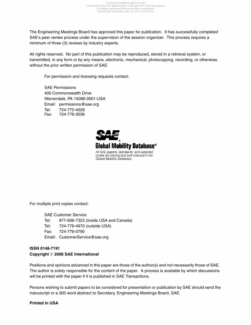
The engine employed in this research was a single cylinder, gasoline port fuel injected, 4-stroke research engine based on a GM Family One, 1.8L series architecture, shown by the photograph of Figure 1. A standard 4-cylinder head is mounted on top of a water cooled barrel, with a custom made bottom end. Only the front cylinder of the head is operational. A fully variable valve timing system named Active Valve Train (AVT); manufactured by Lotus Engineering; was fitted to allow a variable valve timing strategy. Variable quantities of trapped residual gas (TRG) can be captured in this way. For this investigation, the CR was set at 10.5:1. (It is
worth noting that intake air temperature was maintained at a room temperature of 20 degrees Celsius)
Figure 1. Single-cylinder research engine with AVT system
The engine was connected to a Froude AG30 30kW eddy-current dynamometer. A redline ACAP data acquisition system from DSP Technologies Inc. together with a Kistler 6123 piezoelectric pressure transducer and a Horiba MEXA 7100 DEGR emissions analyzer. Port fuel injection was employed, managed by a conventional Lotus V8 engine controller. High speed data were sampled at one degree crank angle intervals. This sample rate is sufficiently high to obtain the salient features of the ion-current signal (as a combustion performance indicator), whilst coarse enough to be realistically used as part of a real time engine control strategy that is compatible with conventional car electronics.
Three combustion regimes were investigated; SI, HCCI and SA-CAI (which occurs in transition regions between SI and HCCI) and where a spark is used to position heat release in the correct time window. This region is not the same as HCCI where ignition occurs due to compression. To enable this investigation, the valve strategy involved two separate profiles, one for CAI/HCCI and one for SI operation. The CAI/HCCI profile had a fixed lift of 2.5mm and fixed duration but variable overlap, which was changed from positive to negative in variable step sizes until the misfire limit was reached. For high power SI operation a high lift (8mm), long duration valve profile was used. During HCCI operation the load was controlled by changing the overlap, so the engine manifold was unthrottled. During SI operation an electronic throttle was used to adjust load. The throttle is also responsible for controlling the engine load during immediate transitions from SI to HCCI and back to SI.
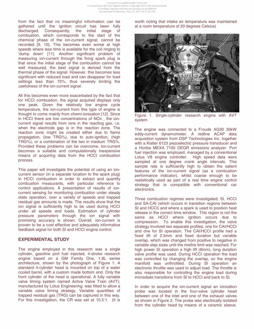
In order to acquire the ion-current signal an ionization probe was located in the four-valve cylinder head between one of the inlet and one of the exhaust valves as shown in Figure 2. The probe was electrically isolated from the cylinder head by means of a ceramic sleeve.
Licensed to Loughborough UniversityLicensed from the SAE Digital Library Copyright 2011 SAE International
E-mailing, copying and internet posting are prohibitedDownloaded Wednesday, May 25, 2011 10:37:28 AM
Author:Gilligan-SID:13282-GUID:52305534-158.125.80.164
The diameter of the sensing element was slightly less than 1mm, and the tip protrusion into the combustion chamber was approximately 3.5 mm.
Figure 2. Photograph of cylinder head showing the location of the ionisation probe
Since the mass of positive ions, such as H3O+, is approximately 30,000 times larger than that of an electron (negative charge), the light electrons can be accelerated much more easily towards the positive electrode than the heavy ions [13], when driven by an applied electromagnetic field. The voltage polarity at the gap of sensing spark plugs was therefore selected such that the small area centre electrode was positive, and the rest of the combustion chamber was negative. This coincides conveniently with the original engine polarity where the engine block is negative.
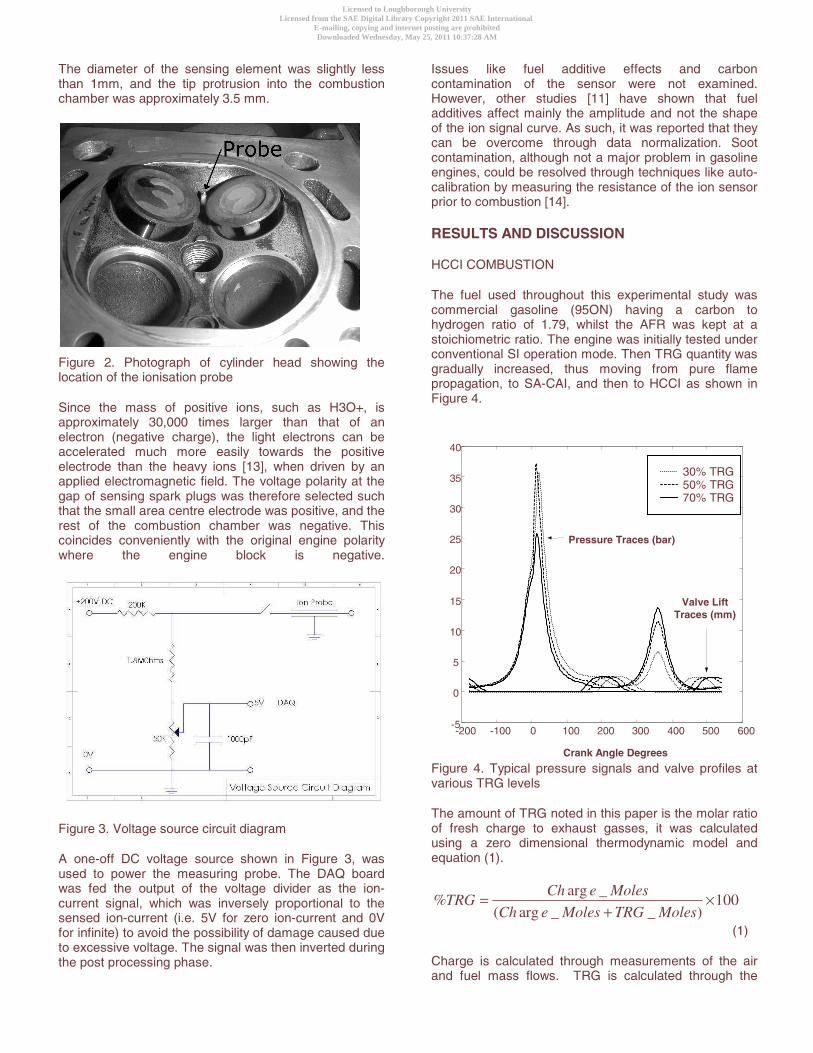
Figure 3. Voltage source circuit diagram
A one-off DC voltage source shown in Figure 3, was used to power the measuring probe. The DAQ board was fed the output of the voltage divider as the ion-current signal, which was inversely proportional to the sensed ion-current (i.e. 5V for zero ion-current and 0V for infinite) to avoid the possibility of damage caused due to excessive voltage. The signal was then inverted during the post processing phase.
Issues like fuel additive effects and carbon contamination of the sensor were not examined. However, other studies [11] have shown that fuel additives affect mainly the amplitude and not the shape of the ion signal curve. As such, it was reported that they can be overcome through data normalization. Soot contamination, although not a major problem in gasoline engines, could be resolved through techniques like auto-calibration by measuring the resistance of the ion sensor prior to combustion [14].
RESULTS AND DISCUSSION
HCCI COMBUSTION
The fuel used throughout this experimental study was commercial gasoline (95ON) having a carbon to hydrogen ratio of 1.79, whilst the AFR was kept at a stoichiometric ratio. The engine was initially tested under conventional SI operation mode. Then TRG quantity was gradually increased, thus moving from pure flame propagation, to SA-CAI, and then to HCCI as shown in Figure 4.
Figure 4. Typical pressure signals and valve profiles at various TRG levels
The amount of TRG noted in this paper is the molar ratio of fresh charge to exhaust gasses, it was calculated using a zero dimensional thermodynamic model and equation (1).
100)__arg(
_arg% ×
+=
MolesTRGMoleseCh
MoleseChTRG
(1)
Charge is calculated through measurements of the air and fuel mass flows. TRG is calculated through the
-200 -100 0 100 200 300 400 500 600-5
0
5
10
15
20
25
30
35
40
Crank Angle Degrees
30% TRG50% TRG70% TRG
Pressure Traces (bar)
Valve Lift Traces (mm)
Licensed to Loughborough UniversityLicensed from the SAE Digital Library Copyright 2011 SAE International
E-mailing, copying and internet posting are prohibitedDownloaded Wednesday, May 25, 2011 10:37:28 AM
Author:Gilligan-SID:13282-GUID:52305534-158.125.80.164
application of the ideal gas law NRTPV = at exhaust valve closure. P and V are both known, while temperature is taken from a reading of the exhaust gases, and N in this case is the amount of TRG moles . The slow response nature of the thermocouple and the effects of the expansion into the exhaust imply an underestimation of the temperature, and hence an overestimation of the number of moles of TRG. However, its usage without any correction factors guarantees the production of nominal values which still correctly capture the changes among TRG levels without suffering the problems that plague NVO-related methods (which, for example, neglects speed).
The maximum amount of TRG that the engine will accept depends on the engine speed. Thus an amount of TRG that is on the edge of HCCI at one speed might be in the middle of the operating region, at another. As such, it does not always make sense to speak in absolute terms of TRG%, especially as TRG tolerance is a very engine specific issue. In this paper, TRG% will be described as low, medium or high, rather than assigning absolute values that cannot be extrapolated to different research.
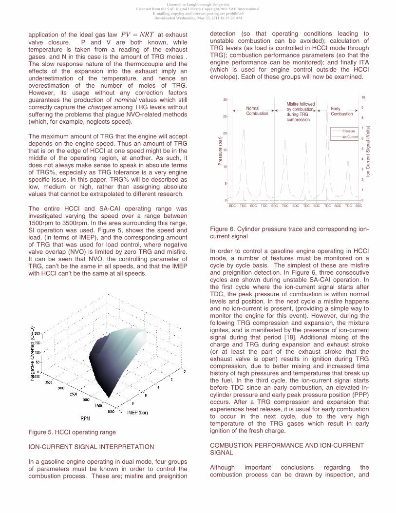
The entire HCCI and SA-CAI operating range was investigated varying the speed over a range between 1500rpm to 3500rpm. In the area surrounding this range, SI operation was used. Figure 5, shows the speed and load, (in terms of IMEP), and the corresponding amount of TRG that was used for load control, where negative valve overlap (NVO) is limited by zero TRG and misfire. It can be seen that NVO, the controlling parameter of TRG, can’t be the same in all speeds, and that the IMEP with HCCI can’t be the same at all speeds.
Figure 5. HCCI operating range
ION-CURRENT SIGNAL INTERPRETATION
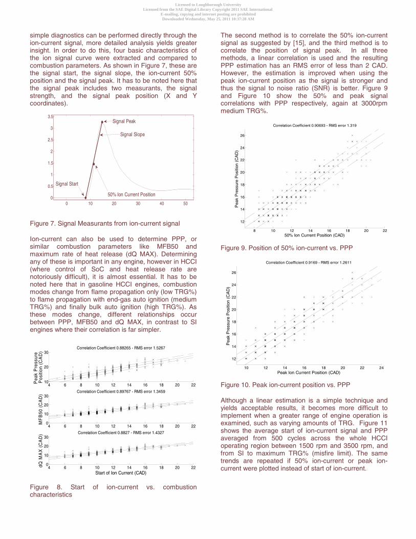
In a gasoline engine operating in dual mode, four groups of parameters must be known in order to control the combustion process. These are; misfire and preignition
detection (so that operating conditions leading to unstable combustion can be avoided); calculation of TRG levels (as load is controlled in HCCI mode through TRG); combustion performance parameters (so that the engine performance can be monitored); and finally ITA (which is used for engine control outside the HCCI envelope). Each of these groups will now be examined.
0
1
2
3
4
5
6
7
8
9
10
Ion
Cur
rent
Sig
nal (
Vol
ts)
BDC TDC TDC BDC TDC TDC BDC TDC TDCBDC BDC BDC BDC
0
5
10
15
20
25
30
Pre
ssur
e (b
ar)
Misfire followedby combustion during TRG compression
Early Combustion
Normal Combustion
Pressure
Ion Current
Figure 6. Cylinder pressure trace and corresponding ion-current signal
In order to control a gasoline engine operating in HCCI mode, a number of features must be monitored on a cycle by cycle basis. The simplest of these are misfire and preignition detection. In Figure 6, three consecutive cycles are shown during unstable SA-CAI operation. In the first cycle where the ion-current signal starts after TDC, the peak pressure of combustion is within normal levels and position. In the next cycle a misfire happens and no ion-current is present, (providing a simple way to monitor the engine for this event). However, during the following TRG compression and expansion, the mixture ignites, and is manifested by the presence of ion-current signal during that period [18]. Additional mixing of the charge and TRG during expansion and exhaust stroke (or at least the part of the exhaust stroke that the exhaust valve is open) results in ignition during TRG compression, due to better mixing and increased time history of high pressures and temperatures that break up the fuel. In the third cycle, the ion-current signal starts before TDC since an early combustion, an elevated in-cylinder pressure and early peak pressure position (PPP) occurs. After a TRG compression and expansion that experiences heat release, it is usual for early combustion to occur in the next cycle, due to the very high temperature of the TRG gases which result in early ignition of the fresh charge.
COMBUSTION PERFORMANCE AND ION-CURRENT SIGNAL
Although important conclusions regarding the combustion process can be drawn by inspection, and
Licensed to Loughborough UniversityLicensed from the SAE Digital Library Copyright 2011 SAE International
E-mailing, copying and internet posting are prohibitedDownloaded Wednesday, May 25, 2011 10:37:28 AM
Author:Gilligan-SID:13282-GUID:52305534-158.125.80.164
simple diagnostics can be performed directly through the ion-current signal, more detailed analysis yields greater insight. In order to do this, four basic characteristics of the ion signal curve were extracted and compared to combustion parameters. As shown in Figure 7, these are the signal start, the signal slope, the ion-current 50% position and the signal peak. It has to be noted here that the signal peak includes two measurants, the signal strength, and the signal peak position (X and Y coordinates).
0 10 20 30 40 500
0.5
1
1.5
2
2.5
3
3.5
Signal Start
Signal Peak
Signal Slope
50% Ion Current Position
Figure 7. Signal Measurants from ion-current signal
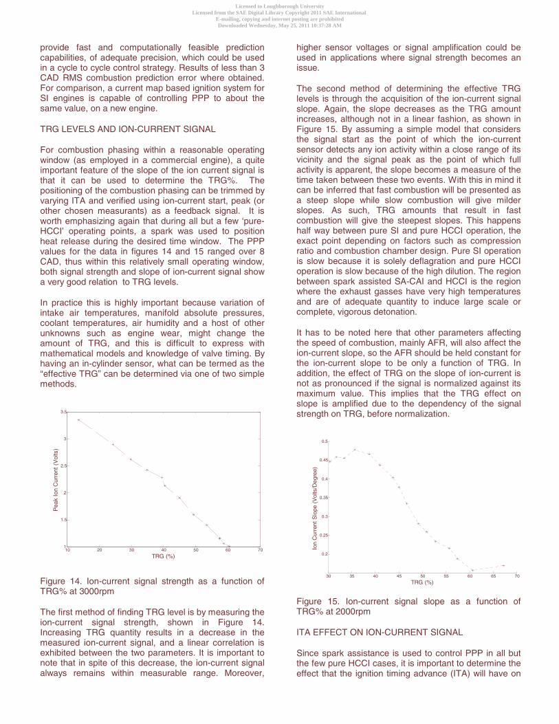
Ion-current can also be used to determine PPP, or similar combustion parameters like MFB50 and maximum rate of heat release (dQ MAX). Determining any of these is important in any engine, however in HCCI (where control of SoC and heat release rate are notoriously difficult), it is almost essential. It has to be noted here that in gasoline HCCI engines, combustion modes change from flame propagation only (low TRG%) to flame propagation with end-gas auto ignition (medium TRG%) and finally bulk auto ignition (high TRG%). As these modes change, different relationships occur between PPP, MFB50 and dQ MAX, in contrast to SI engines where their correlation is far simpler.
Figure 8. Start of ion-current vs. combustion characteristics
The second method is to correlate the 50% ion-current signal as suggested by [15], and the third method is to correlate the position of signal peak. In all three methods, a linear correlation is used and the resulting PPP estimation has an RMS error of less than 2 CAD. However, the estimation is improved when using the peak ion-current position as the signal is stronger and thus the signal to noise ratio (SNR) is better. Figure 9 and Figure 10 show the 50% and peak signal correlations with PPP respectively, again at 3000rpm medium TRG%.
Figure 9. Position of 50% ion-current vs. PPP
Figure 10. Peak ion-current position vs. PPP
Although a linear estimation is a simple technique and yields acceptable results, it becomes more difficult to implement when a greater range of engine operation is examined, such as varying amounts of TRG. Figure 11 shows the average start of ion-current signal and PPP averaged from 500 cycles across the whole HCCI operating region between 1500 rpm and 3500 rpm, and from SI to maximum TRG% (misfire limit). The same trends are repeated if 50% ion-current or peak ion-current were plotted instead of start of ion-current.
4 6 8 10 12 14 16 18 20 2210
20
30Correlation Coefficient 0.88265 - RMS error 1.5267
Pea
k P
ress
ure
Pos
ition
(C
AD
)
4 6 8 10 12 14 16 18 20 220
10
20
30Correlation Coefficient 0.89767 - RMS error 1.3459
MF
B50
(C
AD
)
4 6 8 10 12 14 16 18 20 220
10
20
30Correlation Coefficient 0.8827 - RMS error 1.4327
Start of Ion Current (CAD)
dQ M
AX
(C
AD
)
8 10 12 14 16 18 20 22
12
14
16
18
20
22
24
26
50% Ion Current Position (CAD)P
eak
Pre
ssur
e P
ositi
on (
CA
D)
Correlation Coefficient 0.90693 - RMS error 1.319
10 12 14 16 18 20 22 24
12
14
16
18
20
22
24
26
Peak Ion Current Position (CAD)
Pea
k P
ress
ure
Pos
ition
(C
AD
)
Correlation Coefficient 0.9169 - RMS error 1.2611
Licensed to Loughborough UniversityLicensed from the SAE Digital Library Copyright 2011 SAE International
E-mailing, copying and internet posting are prohibitedDownloaded Wednesday, May 25, 2011 10:37:28 AM
Author:Gilligan-SID:13282-GUID:52305534-158.125.80.164
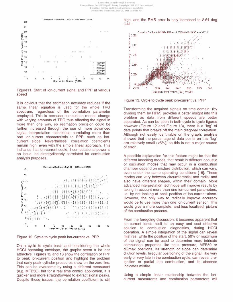
Figure11. Start of ion-current signal and PPP at various speed
It is obvious that the estimation accuracy reduces if the same linear equation is used for the whole TRG spectrum, regardless of the correlation parameter employed. This is because combustion modes change with varying amounts of TRG thus affecting the signal in more than one way, so estimation precision could be further increased through the use of more advanced signal interpretation techniques correlating more than one ion-current characteristic to PPP, such as ion-current slope. Nevertheless; correlation coefficients remain high, even with the simple linear approach. This indicates that ion-current could, if computational power is an issue, be directly/linearly correlated for combustion analysis purposes.
Figure 12. Cycle to cycle peak ion-current vs. PPP
On a cycle to cycle basis and considering the whole HCCI operating envelope, the graphs seem a lot less attractive. Figures 12 and 13 show the correlation of PPP to peak ion-current position and highlight the problem that early peak cylinder pressures show on the zero line. This can be overcome by using a different measurant (e.g. MFB50), but for a real time control application, it is quicker and more straightforward to extract signal peaks. Despite these issues, the correlation coefficient is still
high, and the RMS error is only increased to 2.64 deg CAD.
Figure 13. Cycle to cycle peak ion-current vs. PPP
Transforming the acquired signals on time domain, (by dividing them by RPM) provides a better insight into this problem as data from different speeds are better separated. As can be seen in both cycle to cycle figures however (Figure 12 and Figure 13), there is a “leg” of data points that breaks off the main diagonal correlation. Although not easily identifiable on the graph, analysis showed that the percentage of data points on this “leg” are relatively small (<5%), so this is not a major source of error.
A possible explanation for this feature might be that the different knocking modes, that result in different acoustic or oscillation modes that may occur in a combustion chamber depend on mixture distribution, which can vary, even under the same operating conditions [16]. These modes can vary between circumferential and radial and also have different shapes, within their domain. More advanced interpretation technique will improve results by taking in account more than one ion-current parameters, i.e. by not looking at peak position of ion-current alone. However, the only way to radically improve accuracy would be to use more than one ion-current sensor. This would give a more complete, and less localized, picture of the combustion process.
From the foregoing discussion, it becomes apparent that ion-current lends itself to an easy and cost effective solution to combustion diagnostics, during HCCI operation. A simple integration of the signal can reveal misfires, while the position of the start, 50% or maximum of the signal can be used to determine more intricate combustion properties like peak pressure, MFB50 or dQmax positions. Its strength or slope can determine dilution levels. Irregular positioning of the signal, like very early or very late in the combustion cycle, can reveal pre-ignition or partial late combustion, and its absence indicates misfire.
Using a simple linear relationship between the ion-current measurants and combustion parameters will
4 5 6 7 8 9 10 11 12 13 1411
12
13
14
15
16
17
18
19
20
21
22
Start of Ion Current (CAD)
Pea
k P
ress
ure
Pos
ition
(C
AD
)Correlation Coefficient 0.87346 - RMS error 1.0854
1500rpm 2000rpm2500rpm3000rpm3500rpm
Licensed to Loughborough UniversityLicensed from the SAE Digital Library Copyright 2011 SAE International
E-mailing, copying and internet posting are prohibitedDownloaded Wednesday, May 25, 2011 10:37:28 AM
Author:Gilligan-SID:13282-GUID:52305534-158.125.80.164
provide fast and computationally feasible prediction capabilities, of adequate precision, which could be used in a cycle to cycle control strategy. Results of less than 3 CAD RMS combustion prediction error where obtained. For comparison, a current map based ignition system for SI engines is capable of controlling PPP to about the same value, on a new engine.
TRG LEVELS AND ION-CURRENT SIGNAL
For combustion phasing within a reasonable operating window (as employed in a commercial engine), a quite important feature of the slope of the ion current signal is that it can be used to determine the TRG%. The positioning of the combustion phasing can be trimmed by varying ITA and verified using ion-current start, peak (or other chosen measurants) as a feedback signal. It is worth emphasizing again that during all but a few ‘pure-HCCI’ operating points, a spark was used to position heat release during the desired time window. The PPP values for the data in figures 14 and 15 ranged over 8 CAD, thus within this relatively small operating window, both signal strength and slope of ion-current signal show a very good relation to TRG levels.
In practice this is highly important because variation of intake air temperatures, manifold absolute pressures, coolant temperatures, air humidity and a host of other unknowns such as engine wear, might change the amount of TRG, and this is difficult to express with mathematical models and knowledge of valve timing. By having an in-cylinder sensor, what can be termed as the “effective TRG” can be determined via one of two simple methods.
10 20 30 40 50 60 701
1.5
2
2.5
3
3.5
TRG (%)
Pea
k Io
n C
urre
nt (
Vol
ts)
Figure 14. Ion-current signal strength as a function of TRG% at 3000rpm
The first method of finding TRG level is by measuring the ion-current signal strength, shown in Figure 14. Increasing TRG quantity results in a decrease in the measured ion-current signal, and a linear correlation is exhibited between the two parameters. It is important to note that in spite of this decrease, the ion-current signal always remains within measurable range. Moreover,
higher sensor voltages or signal amplification could be used in applications where signal strength becomes an issue.
The second method of determining the effective TRG levels is through the acquisition of the ion-current signal slope. Again, the slope decreases as the TRG amount increases, although not in a linear fashion, as shown in Figure 15. By assuming a simple model that considers the signal start as the point of which the ion-current sensor detects any ion activity within a close range of its vicinity and the signal peak as the point of which full activity is apparent, the slope becomes a measure of the time taken between these two events. With this in mind it can be inferred that fast combustion will be presented as a steep slope while slow combustion will give milder slopes. As such, TRG amounts that result in fast combustion will give the steepest slopes. This happens half way between pure SI and pure HCCI operation, the exact point depending on factors such as compression ratio and combustion chamber design. Pure SI operation is slow because it is solely deflagration and pure HCCI operation is slow because of the high dilution. The region between spark assisted SA-CAI and HCCI is the region where the exhaust gasses have very high temperatures and are of adequate quantity to induce large scale or complete, vigorous detonation.
It has to be noted here that other parameters affecting the speed of combustion, mainly AFR, will also affect the ion-current slope, so the AFR should be held constant for the ion-current slope to be only a function of TRG. In addition, the effect of TRG on the slope of ion-current is not as pronounced if the signal is normalized against its maximum value. This implies that the TRG effect on slope is amplified due to the dependency of the signal strength on TRG, before normalization.
30 35 40 45 50 55 60 65 70
0.2
0.25
0.3
0.35
0.4
0.45
0.5
TRG (%)
Ion
Cur
rent
Slo
pe (
Vol
ts/D
egre
e)
Figure 15. Ion-current signal slope as a function of TRG% at 2000rpm
ITA EFFECT ON ION-CURRENT SIGNAL
Since spark assistance is used to control PPP in all but the few pure HCCI cases, it is important to determine the effect that the ignition timing advance (ITA) will have on
Licensed to Loughborough UniversityLicensed from the SAE Digital Library Copyright 2011 SAE International
E-mailing, copying and internet posting are prohibitedDownloaded Wednesday, May 25, 2011 10:37:28 AM
Author:Gilligan-SID:13282-GUID:52305534-158.125.80.164
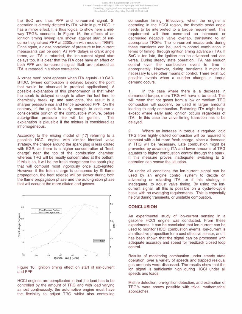
the SoC and thus PPP and ion-current signal. SI operation is directly dictated by ITA, while in pure HCCI it has a minor effect. It is thus logical to show here a mid-way TRG% scenario. In Figure 16, the effects of an ignition timing sweep are shown against start of ion-current signal and PPP at 2200rpm with medium TRG%. Once again, a close correlation of pressure to ion-current measurants can be seen. As PPP delays in crank angle terms, as ITA is retarded, the ion-current signal start delays too. It is clear that the ITA does have an effect on both PPP and ion-current signal. Both are retarded as ITA is retarded in a close correlation.
A ‘cross over’ point appears when ITA equals -10 CAD-BTDC, (where combustion is delayed beyond the point that would be observed in practical applications). A possible explanation of this phenomenon is that when the spark is delayed enough to allow the fuel time to chemically break up and auto-ignite, the result is a sharper pressure rise and hence advanced PPP. On the contrary, if the spark is early enough to consume a considerable portion of the combustible mixture, before auto-ignition pressure rise will be gentler. This explanation is plausible if the mixture is considered as inhomogeneous.
According to the mixing model of [17] referring to a gasoline HCCI engine with almost identical valve strategy, the charge around the spark plug is less diluted with EGR, as there is a higher concentration of ‘fresh charge’ near the top of the combustion chamber, whereas TRG will be mostly concentrated at the bottom. If this is so, it will be the fresh charge near the spark plug that will combust most vigorously once auto-ignited. However, if the fresh charge is consumed by SI flame propagation, the heat release will be slower during both the flame propagation phase and the auto-ignition phase that will occur at the more diluted end gasses.
Figure 16. Ignition timing effect on start of ion-current and PPP
HCCI engines are complicated in that the load has to be controlled by the amount of TRG and with load varying almost continuously; the automotive engine must have the flexibility to adjust TRG whilst also controlling
combustion timing. Effectively, when the engine is operating in the HCCI region, the throttle pedal angle needs to be interpreted to a torque requirement. This requirement will then command an increased or decreased negative valve overlap, translating to an appropriate TRG%. The ion-current measurants during these transients can be used to control combustion in terms of timing, through ignition timing advance (ITA). If SoC is too late, the ignition can be advanced and vice versa. During steady state operation, ITA has enough control over the combustion event to time it appropriately. However, during transients it might be necessary to use other means of control. There exist two possible events when a sudden change in torque demand occurs.
1. In the case where there is a decrease in demanded torque, more TRG will have to be used. This will mean that hot gases from a low or medium TRG combustion will suddenly be used in larger amounts leading to early combustion. Retarding ITA might help: except where early auto ignition occurs regardless of ITA. In this case the valve timing transition has to be delayed.
2. Where an increase in torque is required, cold TRG from highly diluted combustion will be required to combust with a lot more fresh charge, since a decrease in TRG will be necessary. Late combustion might be prevented by advancing ITA and lower amounts of TRG equates to higher combustion control through the spark. If this measure proves inadequate, switching to SI operation can rescue the situation.
So under all conditions the ion-current signal can be used by an engine control system to decide on advancing or retarding ITA; or if this strategy is inadequate, to adjust valve timing. By using the ion-current signal, all this is possible on a cycle-to-cycle basis with no averaging requirements. This is especially helpful during transients, or unstable combustion.
CONCLUSION
An experimental study of ion-current sensing in a gasoline HCCI engine was conducted. From these experiments, it can be concluded that ion-current can be used to monitor HCCI combustion events. Ion-current is an attractive proposition for a cost effective sensor, and it has been shown that the signal can be processed with adequate accuracy and speed for feedback closed loop control.
Results of monitoring combustion under steady state operation, over a variety of speeds and trapped residual gas amounts were discussed. The results show that the ion signal is sufficiently high during HCCI under all speeds and loads.
Misfire detection, pre-ignition detection, and estimation of TRG% were shown possible with trivial mathematical approaches.
-35 -30 -25 -20 -15 -10 -5 05
10
15
20
25
30
Ignition Timing (CAD)
Cra
nk A
ngle
Deg
rees
5
5.5
6
6.5
7
7.5
8
IME
P
IMEP
Peak Pressure PositionIon Current Signal Start
Licensed to Loughborough UniversityLicensed from the SAE Digital Library Copyright 2011 SAE International
E-mailing, copying and internet posting are prohibitedDownloaded Wednesday, May 25, 2011 10:37:28 AM
Author:Gilligan-SID:13282-GUID:52305534-158.125.80.164
PPP, MFB50 and dQmax were all determined with RMS errors less than 2 deg CAD, when a specific engine operating condition was examined. When a linear relationship that would cover the whole HCCI operating spectrum, from 0% TRG to maximum TRG, was derived, the maximum error rose to 2.64 deg CAD, remaining accurate enough for feedback purposes.
A straightforward monitoring of the effect of ITA on PPP is possible through ion-current signal monitoring.
Overall, ion-current was proven to be a cost effective and adequately informative feedback signal for both SI and HCCI engine control.
REFERENCES
1. Calcote, H.F. Ion production and recombination in flames. in 8th Symposium on Combustion. 1962. 2. Calcote, H.F. Ion and electron profiles in flames. in 9th Symposium on Combustion. 1963. 3. Shuler, K.E., Ionization in High-Temperature Gases, Academic Press. (1963) 4. Shimasaki, Y., M. Kanehiro, S. Baba, S. Maruyama, T. Hisaki, and S. Miyata, Spark plug voltage analysis for monitoring combustion in an internal combustion engine, SAE Technical Paper Series. 930461:(1993). 5. Saitzkoff, A., R. Reinmann, T. Berglind, and M. Glavmo, An ionization equilibrium analysis of the spark plug as an ionization sensor, SAE Technical Paper Series. 960337:(1996). 6. Yoshiyama, S., E. Tomita, and Y. Hamamoto, Fundamental Study on Combustion Diagnostics Using a Spark Plug as Ion Probe, SAE Technical Paper Series. 2000-01-2828:(2000). 7. Reinmann, R., A. Saitzkoff, F. Mauss, and M. Glavmo, Local Air-Fuel Ratio Measurements Using the Spark Plug as an Ionization Sensor, SAE Technical Paper Series. 970856:(1997). 8. Aithal, S.M., A.R. White, V.V. Subramaniam, V. Babu, and G. Rizzoni, A Chemical Kinetics Model of Current Signatures in an Ionization Sensor, AIAA Plasmadynamics and Lasers Conference. AIAA-1999-3606:(1999). 9. Peron, L., A. Charlet, P. Higlen, B. Moreau, and J. Burq, Limitations of Ionization-current Sensors and Comparison with Cylinder Pressure Sensors, SAE Technical Paper Series. 2000-01-2830:(2000). 10. Asano, M., A. Ito, T. Kuma, M. Kajitani, M. Takeuchi, Y. Fukumura, and M. Izumi, Further Development of an Ion-current Combustion Control System, SAE Technical Paper Series. 2001-01-0266:(2001). 11. Malaczynski, G.W. and M.E. Baker, Real-Time Digital Signal Processing of Ionization-Current for Engine Diagnostics and Control, SAE Technical Paper Series. 2003-01-1119:(2003). 12. Strandh, P., M. Christensen, J. Bengtsson, R. Johansson, A. Vressner, P. Tunestal, and B. Johansson, Ion-Current Sensing for HCCI Combustion Feedback, SAE Technical Paper Series. 2003-01-3216:(2003).
13. Kiencke, U. and L. Nielsen, Automotive Control Systems, SAE International. (2000) 14. Glavmo, M., P. Spadafora, and R. Bosch, Closed Loop Start of Combustion Control Utilizing Ionization Sensing in a Diesel Engine, SAE Technical Paper Series. 1999-01-0549:(1999). 15. Strandh, P., J. Bengtsson, R. Johansson, P. Tunestal, and B. Johansson, Cycle-to-cycle Control of a Dual-Fuel HCCI Engine, SAE Technical Paper Series. 2004-01-0941:(2004). 16. Coricione, F.E., M. Vaglieco, and S. Merola. Evaluation of Knocking Combustion by an Ion-current System and Optical Diagnostics of Radical Species. in The Sixth International Symposium on diagnostics and Modelling of Combustion in Internal Combustion Engines. 2004. COMODIA 2004. 17. Zhao, H., J. Li, T. Ma, and N. Ladommatos, Performance and Analysis of a Four Stroke Multi-cylinder Gasoline Engine with CAI Combustion, SAE Technical Paper Series. 2002-01-0420:(2002). 18. Koopmans, L., Backlund, O. and Denbratt, I. Cycle to cycle variations: Their influence on cycle resolved gas temperature and unburned hydrocarbons from a camless gasoline compression ignition engine. SAE Technical Paper Series, 2002-01-0110: (2002)
ABBREVIATIONS
AFR: Air Fuel Ratio
CAD: Crank Angle Degrees
dQ: Rate of Heat Released
dQMAX: Maximum Rate of Heat Release
HCCI: Homogenous Charge Compression Ignition
ITA: Ignition Timing Advance
MFB50: 50% Mass Fraction Burned
NOx: Oxides of Nitrogen
NVO: Negative Valve Overlap
PPP: Position of Peak cylinder Pressure
RMS: Root Mean Squared
RPM: Engine Revolutions Per Minute
SA-CAI: Spark Assisted Controlled Auto ignition
SI: Spark Ignition
SNR: Signal to Noise Ratio
SoC: Start of Combustion
TRG: Trapped Residual Gas
Licensed to Loughborough UniversityLicensed from the SAE Digital Library Copyright 2011 SAE International
E-mailing, copying and internet posting are prohibitedDownloaded Wednesday, May 25, 2011 10:37:28 AM
Author:Gilligan-SID:13282-GUID:52305534-158.125.80.164


![HCCI - Update of Progress 2005 - US Department of Energy · HCCI – Update of Progress 2005 HCCI HCCI ... M EP [b a r] B S F C [g/k W-hr] ... Typically used in 2-Stroke Engines at](https://img.pdfslide.us/doc/110x75/5ac4ebc77f8b9a220b8d1053/hcci-update-of-progress-2005-us-department-of-energy-update-of-progress.jpg)