Embed Size (px)
Citation preview
FLS 2010 WorkshopMarch 4th, 2010
Recent Progress in Pulsed Optical Synchronization Systems
Franz X. Kärtner
Department of Electrical Engineering and Computer Science and Research Laboratory of Electronics, Massachusetts Institute of Technology
Cambridge, MA, USA
2
Acknowledgement
Students
Hyunil ByunJonathan CoxAnatoly KhiloMichelle Sander
Postdocs:
J. Kim (KAIST, Korea)Amir NejadmalayeriNoah Chang
Colleagues and Visitors:
E. Ippen, J. G. Fujimoto, L. Kolodziejski, F. Wong and M. Perrott
DESY: F. Loehl, F. Ludwig, A. Winter
3
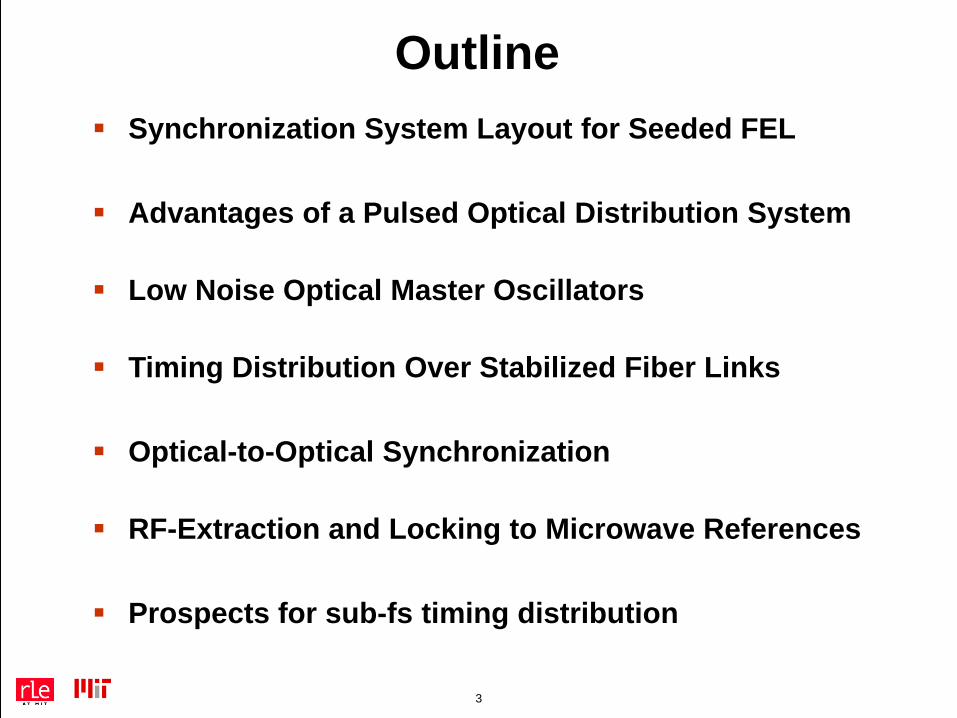
Outline Synchronization System Layout for Seeded FEL
Advantages of a Pulsed Optical Distribution System
Low Noise Optical Master Oscillators
Timing Distribution Over Stabilized Fiber Links
Optical-to-Optical Synchronization
RF-Extraction and Locking to Microwave References
Prospects for sub-fs timing distribution
4
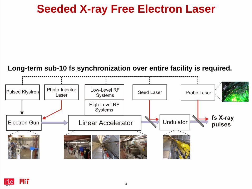
Seeded X-ray Free Electron Laser
Long-term sub-10 fs synchronization over entire facility is required.
5
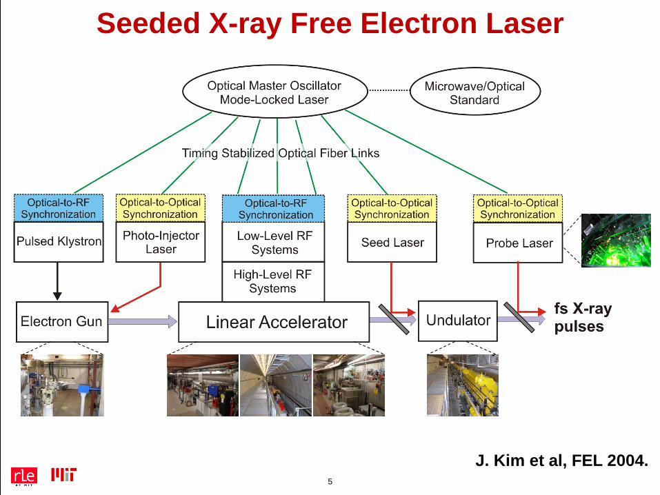
Seeded X-ray Free Electron Laser
J. Kim et al, FEL 2004.
6
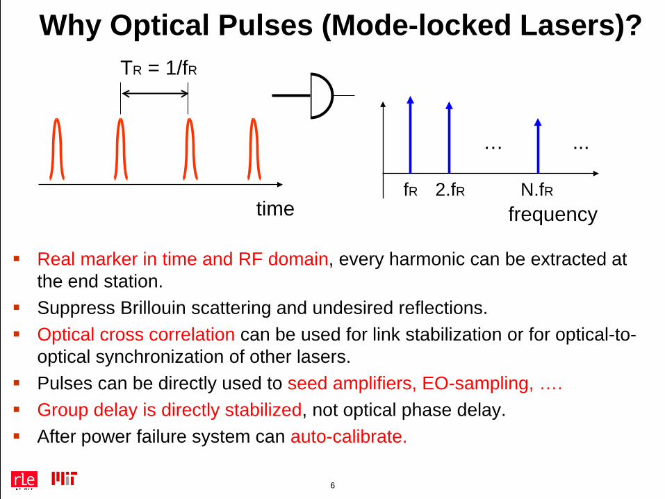
Why Optical Pulses (Mode-locked Lasers)?
Real marker in time and RF domain, every harmonic can be extracted at the end station.
Suppress Brillouin scattering and undesired reflections. Optical cross correlation can be used for link stabilization or for optical-to-
optical synchronization of other lasers. Pulses can be directly used to seed amplifiers, EO-sampling, …. Group delay is directly stabilized, not optical phase delay. After power failure system can auto-calibrate.
frequency
… ...
fR 2.fR N.fR
TR = 1/fR
time
7
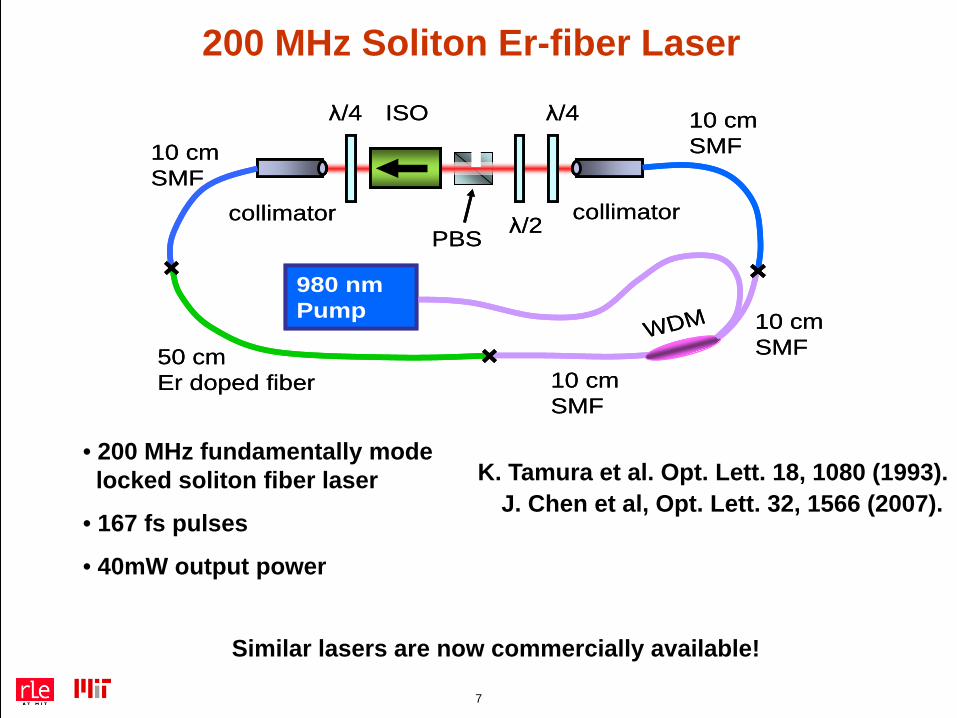
200 MHz Soliton Er-fiber Laser
• 200 MHz fundamentally modelocked soliton fiber laser
• 167 fs pulses
• 40mW output power
ISO
PBS
λ/4
λ/2
λ/4
collimatorcollimator
WDM980 nm Pump
10 cmSMF
50 cmEr doped fiber 10 cm
SMF
10 cmSMF
10 cmSMF
ISO
PBS
λ/4
λ/2
λ/4
collimatorcollimator
WDM980 nm Pump
10 cmSMF
50 cmEr doped fiber 10 cm
SMF
10 cmSMF
10 cmSMF
J. Chen et al, Opt. Lett. 32, 1566 (2007).
Similar lasers are now commercially available!
K. Tamura et al. Opt. Lett. 18, 1080 (1993).
8
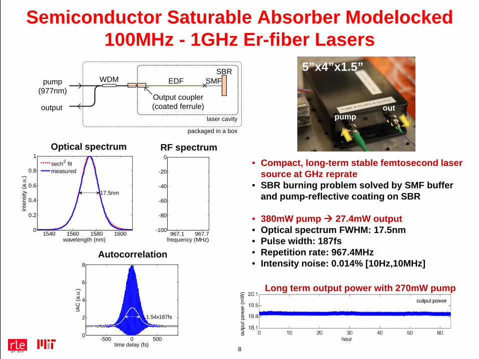
Semiconductor Saturable Absorber Modelocked 100MHz - 1GHz Er-fiber Lasers
EDFSBR
output
WDM
Output coupler(coated ferrule)
pump (977nm)
SMF
laser cavity
packaged in a box
1540 1560 1580 16000
0.2
0.4
0.6
0.8
1
wavelength (nm)
inte
nsity
(a.u
.)
17.5nm
sech2 fitmeasured
• Compact, long-term stable femtosecond laser source at GHz reprate
• SBR burning problem solved by SMF buffer and pump-reflective coating on SBR
• 380mW pump 27.4mW output• Optical spectrum FWHM: 17.5nm• Pulse width: 187fs• Repetition rate: 967.4MHz• Intensity noise: 0.014% [10Hz,10MHz]
967.1 967.7-100
-80
-60
-40
-20
0
frequency (MHz)
Optical spectrum RF spectrum
-500 0 5000
2
4
6
8
time delay (fs)
IAC
(a.u
.)
1.54x187fs
Autocorrelation
5”x4”x1.5”
pumpout
Long term output power with 270mW pump
9
Sensitive Time Delay Measurements by
Balanced Optical Cross Correlation
10
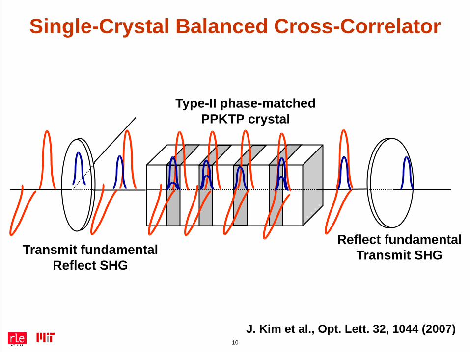
Reflect fundamentalTransmit SHGTransmit fundamental
Reflect SHG
Type-II phase-matchedPPKTP crystal
Single-Crystal Balanced Cross-Correlator
J. Kim et al., Opt. Lett. 32, 1044 (2007)
11
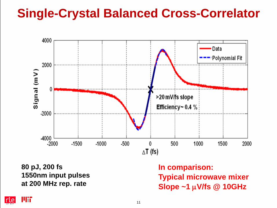
In comparison:Typical microwave mixerSlope ~1 µV/fs @ 10GHz
Single-Crystal Balanced Cross-Correlator
80 pJ, 200 fs 1550nm input pulsesat 200 MHz rep. rate
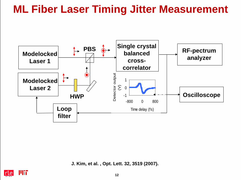
ML Fiber Laser Timing Jitter Measurement
ModelockedLaser 1
ModelockedLaser 2
HWP
PBS Single crystal balanced
cross-correlator
Oscilloscope
RF-pectrumanalyzer
-1
0
1
-800 0 800
Time delay (fs)D
etec
tor
outp
ut
(V)
Loop filter
J. Kim, et al. , Opt. Lett. 32, 3519 (2007).
12
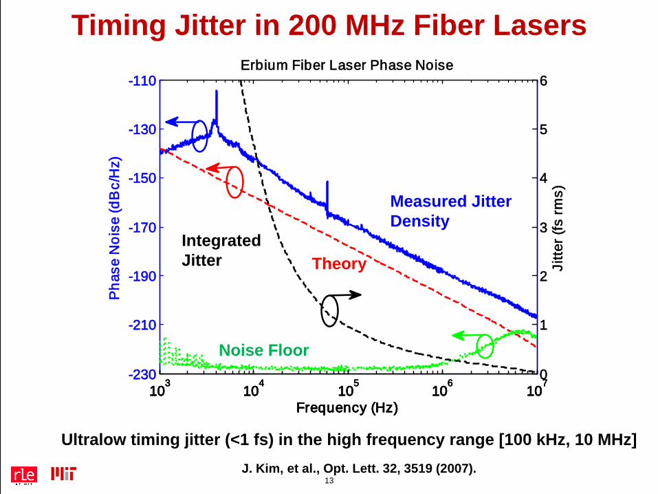
13
Ultralow timing jitter (<1 fs) in the high frequency range [100 kHz, 10 MHz]J. Kim, et al., Opt. Lett. 32, 3519 (2007).
103
104
105
106
107
-230
-210
-190
-170
-150
-130
-110
Pha
se N
oise
(dB
c/H
z)
Frequency (Hz)
IntegratedMeasuredTheoryNoise Floor
103
104
105
106
1070
1
2
3
4
5
6
Frequency (Hz)
Jitte
r (fs
rms)
Erbium Fiber Laser Phase Noise
Timing Jitter in 200 MHz Fiber Lasers
Noise Floor
Integrated Jitter
Measured JitterDensity
Theory
14
Timing - StabilizedFiber Links
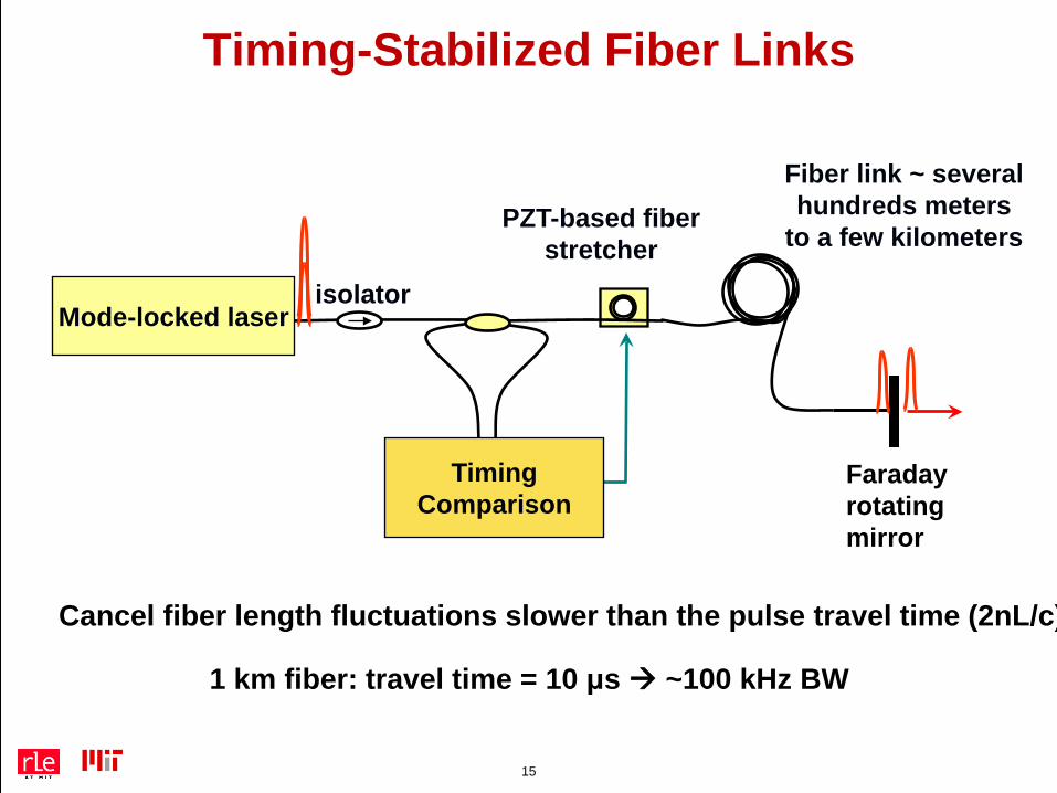
15
PZT-based fiber stretcher
Mode-locked laser
Fiber link ~ several hundreds meters
to a few kilometers
isolator
TimingComparison
Faradayrotatingmirror
Cancel fiber length fluctuations slower than the pulse travel time (2nL/c)
1 km fiber: travel time = 10 μs ~100 kHz BW
Timing-Stabilized Fiber Links
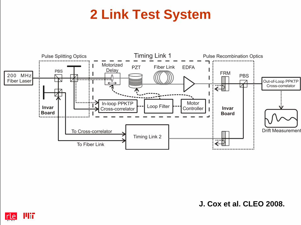
2 Link Test System
J. Cox et al. CLEO 2008.
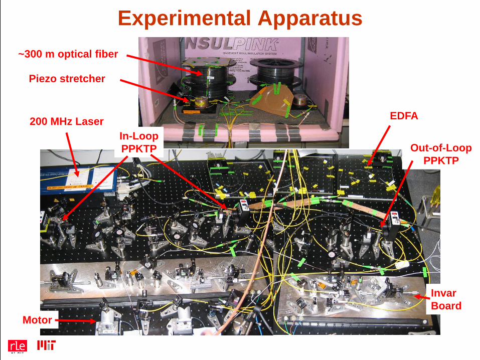
Experimental Apparatus~300 m optical fiber
Piezo stretcher
200 MHz Laser EDFA
Invar Board
Motor
In-LoopPPKTP Out-of-Loop
PPKTP
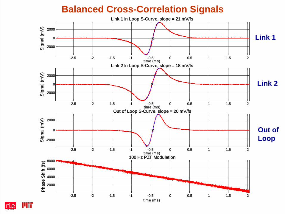
Balanced Cross-Correlation Signals
-2.5 -2 -1.5 -1 -0.5 0 0.5 1 1.5 2
-2000
0
2000
Link 1 In Loop S-Curve, slope = 21 mV/fs
Sig
nal (
mV
)
t ime (ms)
-2.5 -2 -1.5 -1 -0.5 0 0.5 1 1.5 2
-2000
0
2000
Link 2 In Loop S-Curve, slope = 18 mV/fs
Sig
nal (
mV
)
t ime (ms)
-2.5 -2 -1.5 -1 -0.5 0 0.5 1 1.5 2
-2000
0
2000
Out of Loop S-Curve, slope = 20 mV/fs
Sig
nal (
mV
)
t ime (ms)
-2.5 -2 -1.5 -1 -0.5 0 0.5 1 1.5 2
2000
4000
6000
8000100 Hz PZT Modulation
Pha
se S
hift
(fs)
t ime (ms)
Link 1
Link 2
Out ofLoop
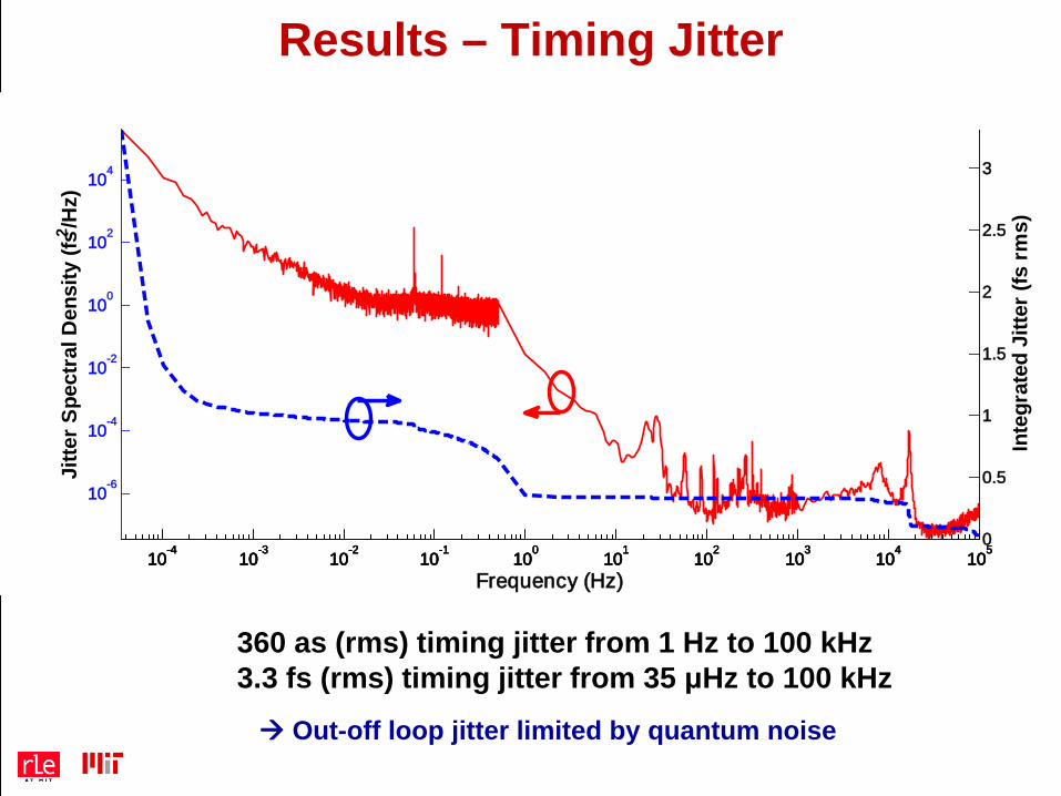
Results – Timing Jitter
360 as (rms) timing jitter from 1 Hz to 100 kHz3.3 fs (rms) timing jitter from 35 μHz to 100 kHz
10-4
10-3
10-2
10-1
100
101
102
103
104
105
10-6
10-4
10-2
100
102
104
Jitte
r Spe
ctra
l Den
sity
(fs2 /H
z)
Frequency (Hz)10
-410
-310
-210
-110
010
110
210
310
410
50
0.5
1
1.5
2
2.5
3
Inte
grat
ed J
itter
(fs
rms)
Out-off loop jitter limited by quantum noise
20
Optical-to-Optical Synchronization
21
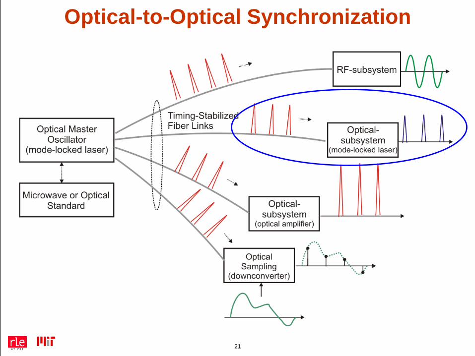
Optical-to-Optical Synchronization
22
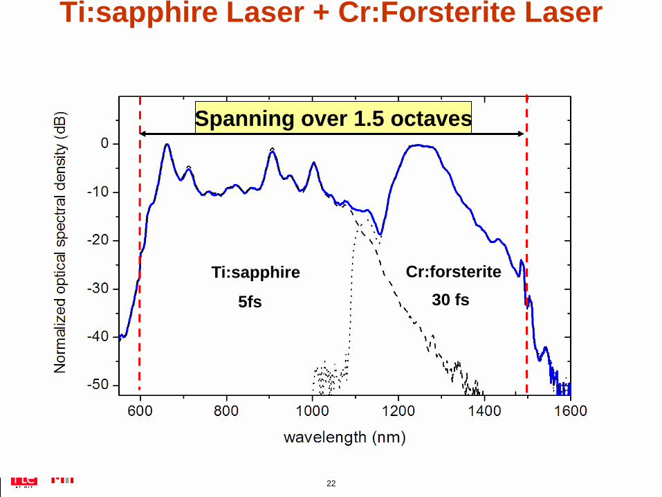
Ti:sapphire Laser + Cr:Forsterite Laser
Ti:sapphire Cr:forsterite
Spanning over 1.5 octaves
5fs 30 fs
23
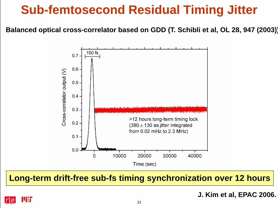
Sub-femtosecond Residual Timing Jitter
J. Kim et al, EPAC 2006.
Long-term drift-free sub-fs timing synchronization over 12 hours
Balanced optical cross-correlator based on GDD (T. Schibli et al, OL 28, 947 (2003))
24
Optical-to-RF Conversion or
Optical-to-RF Lockingnecessary for
Locking OMO to RMO
25
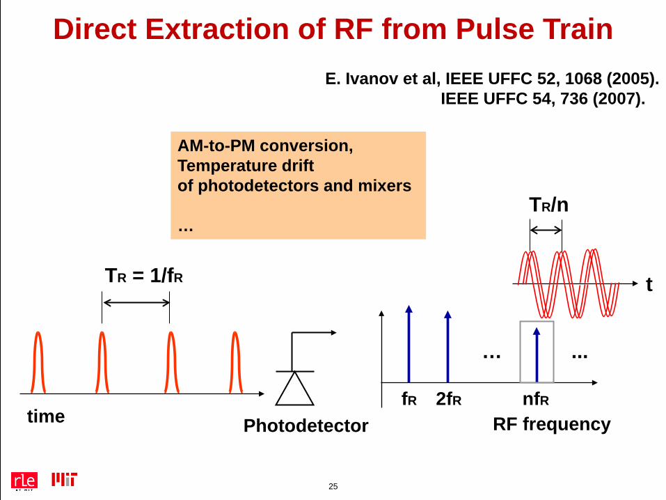
Direct Extraction of RF from Pulse Train
AM-to-PM conversion,Temperature driftof photodetectors and mixers
…
RF frequency
… ...
fR 2fR nfR
TR = 1/fR
time Photodetector
t
TR/n
E. Ivanov et al, IEEE UFFC 52, 1068 (2005). IEEE UFFC 54, 736 (2007).
26
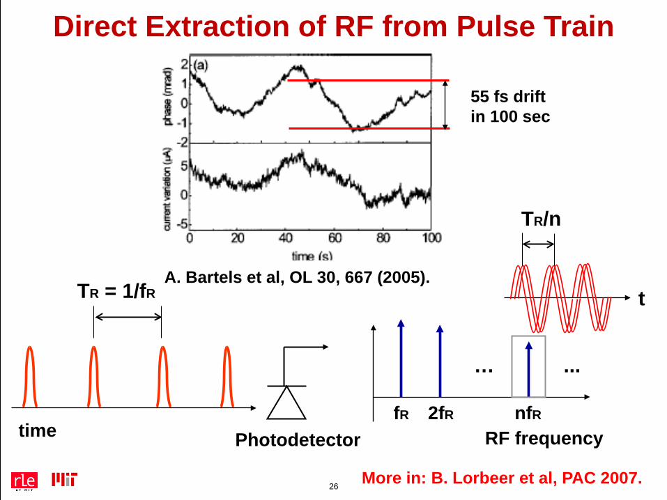
Direct Extraction of RF from Pulse Train
RF frequency
… ...
fR 2fR nfR
TR = 1/fR
time Photodetector
t
TR/n
55 fs driftin 100 sec
A. Bartels et al, OL 30, 667 (2005).
More in: B. Lorbeer et al, PAC 2007.
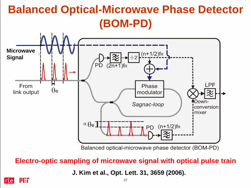
MicrowaveSignal
27
Balanced Optical-Microwave Phase Detector(BOM-PD)
J. Kim et al., Opt. Lett. 31, 3659 (2006).
Electro-optic sampling of microwave signal with optical pulse train
28
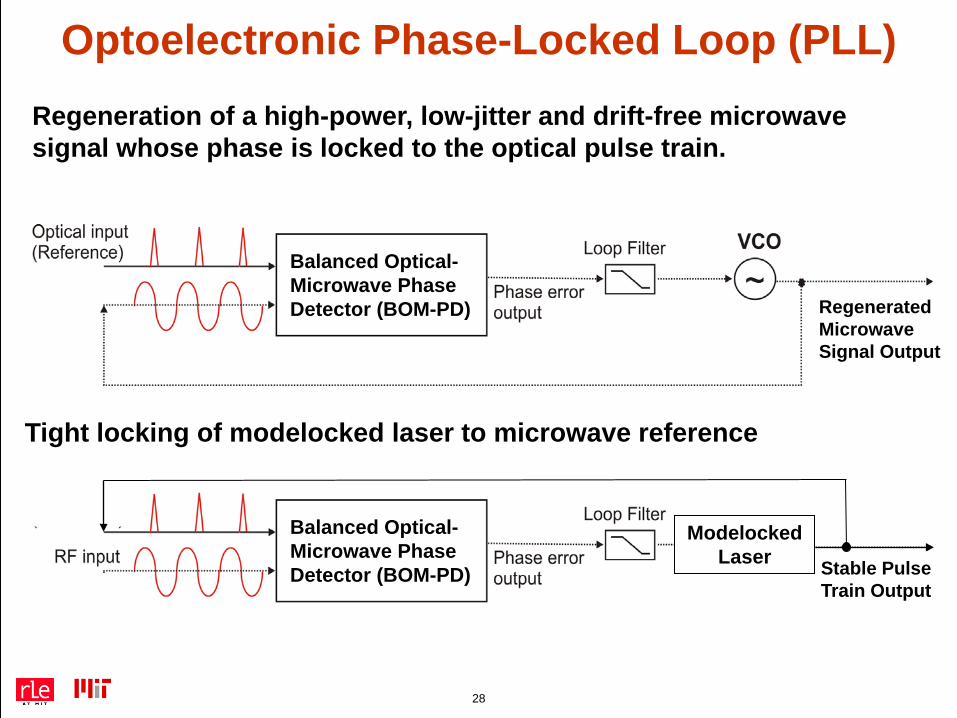
Optoelectronic Phase-Locked Loop (PLL)Regeneration of a high-power, low-jitter and drift-free microwave signal whose phase is locked to the optical pulse train.
Balanced Optical-Microwave Phase Detector (BOM-PD) Regenerated
Microwave Signal Output
Tight locking of modelocked laser to microwave reference
Balanced Optical-Microwave Phase Detector (BOM-PD) Stable Pulse
Train Output
Modelocked Laser
29
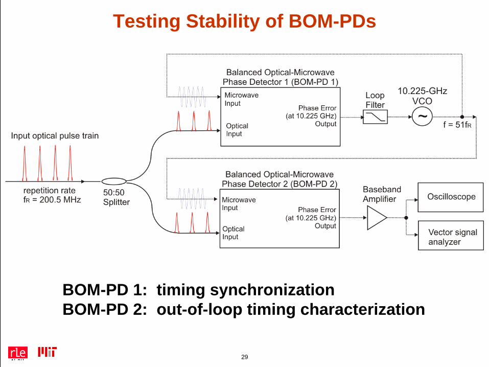
Testing Stability of BOM-PDs
BOM-PD 1: timing synchronizationBOM-PD 2: out-of-loop timing characterization
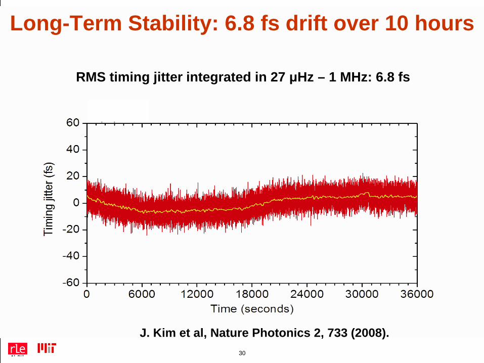
RMS timing jitter integrated in 27 μHz – 1 MHz: 6.8 fs
30
Long-Term Stability: 6.8 fs drift over 10 hours
J. Kim et al, Nature Photonics 2, 733 (2008).
31
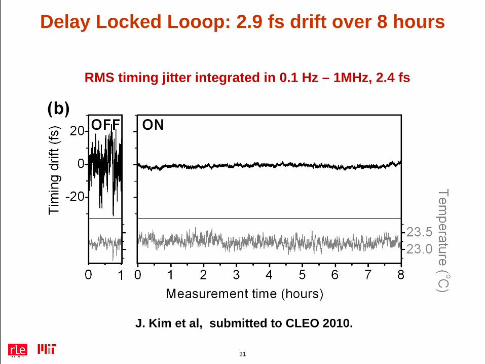
Delay Locked Looop: 2.9 fs drift over 8 hours
J. Kim et al, submitted to CLEO 2010.
RMS timing jitter integrated in 0.1 Hz – 1MHz, 2.4 fs
32
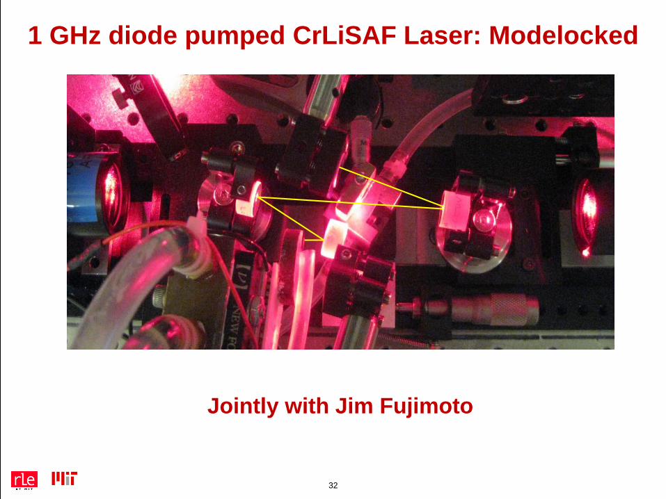
1 GHz diode pumped CrLiSAF Laser: Modelocked
Jointly with Jim Fujimoto
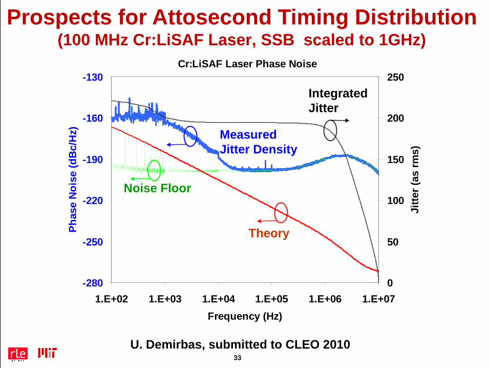
Prospects for Attosecond Timing Distribution(100 MHz Cr:LiSAF Laser, SSB scaled to 1GHz)
U. Demirbas, submitted to CLEO 2010
Cr:LiSAF Laser Phase Noise
-280
-250
-220
-190
-160
-130
1.E+02 1.E+03 1.E+04 1.E+05 1.E+06 1.E+07Frequency (Hz)
Phas
e N
oise
(dB
c/H
z)
0
50
100
150
200
250
Jitte
r (as
rms)
Noise Floor
Theory
Measured Jitter Density
IntegratedJitter
Cr:LiSAF Laser Phase Noise
-280
-250
-220
-190
-160
-130
1.E+02 1.E+03 1.E+04 1.E+05 1.E+06 1.E+07Frequency (Hz)
Phas
e N
oise
(dB
c/H
z)
0
50
100
150
200
250
Jitte
r (as
rms)
Noise Floor
Theory
Measured Jitter Density
IntegratedJitter
33
34
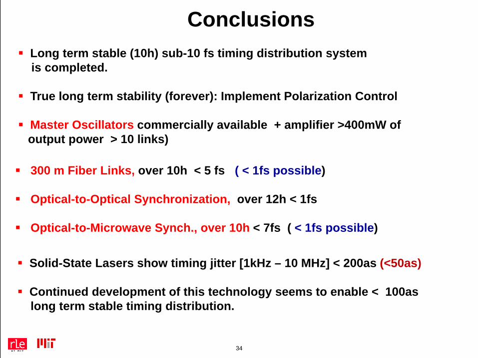
Conclusions Long term stable (10h) sub-10 fs timing distribution system
is completed.
True long term stability (forever): Implement Polarization Control
Master Oscillators commercially available + amplifier >400mW of output power > 10 links)
300 m Fiber Links, over 10h < 5 fs ( < 1fs possible)
Optical-to-Optical Synchronization, over 12h < 1fs
Optical-to-Microwave Synch., over 10h < 7fs ( < 1fs possible)
Solid-State Lasers show timing jitter [1kHz – 10 MHz] < 200as (<50as)
Continued development of this technology seems to enable < 100as long term stable timing distribution.