Embed Size (px)
Citation preview
RECENT DEVELOPMENTS IN PLASMA SPRAYED THERMAL BARRIER COATINGS
Drs. P. FAUCHAIS, A. VARDELLE and M. VARDELLE
L.M.C.T.S. - Equips Plasma, Laser, Mat&iaux Universiti de Limoges - UPRES A 6015 - Faculti des Sciences
123, Avenue Albert Thomas - 87060 LIMOGES Cedex - FRANCE
Abstract
This paper presents a review of our present knowledge in the formation of plasma sprayed Thermal Barrier Coatings (TBCs). The following points are examined for TBCs made of zirconia partially stabilised with 8 wt % of yttria :
characteristic times for particle flattening, splat cooling and solidification with the corresponding cooling rates and microstructure.
_ critical preheating temperature of substrates or previously deposited layers to achieve a good contact with splats. An explanation of the effect of this critical temperature is proposed.
times between two impact events at the same. location and two successive passes. The consequences on the mean temperature within coating in conjunction are underlined for various substrate and coating cooling devices.
the effect of substrate critical temperature and substrate oxidation stage on coating adhesion/ cohesion.
- splat layering and temperature conditions at which a columnar structure can grow through the whole coating. The consequences on stresses develop- ment during and after spraying and coating Young’s modulus, are discussed.
- at last, the parameters which have to be controlled during spraying to achieve a much better reproducibility of coatings. A special emphasise is given to torch voltage fluctuations related to electrodes erosion, powder injection conditions and finally substrate and coating temperature before (preheating) during and after (cooling) spraying.
1. INTRODUCTION
Thermal barrier coatings (TBCs) are now included as part of the initial engine of turbine- powered aircraft?.. They make them possible to achieve an average reduction in the metal temperature for turbine blades of 50 to 80°C and reduction of blade hot-spot temperature of up to 139°C. The latter are only a fraction of the capability of TBCs. estimated at 170°C or more [l]. TBCs have also been used in land-based turbine combustors for 10 years, and in diesel engines where graded coatings are highly effective. In all uses, the purpose is to enhance component durability while running the engine operating temperature. In this paper TBCs for diesel engines will not be considered. The difference between nominal requirements for aircraft and power generation turbine applications are summarized in table 1 [Z].
Requirement Commercial aircraft Power generation Number of cycles 8000 2,400 Total hours 8000 24,000 Hours at peak conditions 3cQ 24,COO Peak surface temperature >1204”C (22WF) < 1204°C (2200°F) Peak bond coat temperature 1093°C (2OWF) 954°C (1750’F) Relative size Ix 5x
Table 1 : Comparison of nominal TBC requirements for aircraft and power generation turbine applications [2].
Paper presented at an AGARD SMP Meering on “Thermal Barrier Coonngs”, held in Aalborg, Denmark, 15-16 October 1997, and published in R-823.
3-2
The main criteria for power generation use of
TBCs arc the time and temperature effects on bond
coat and substrate, coating densification and changes
in thermal or mechanical properties of the coatings.
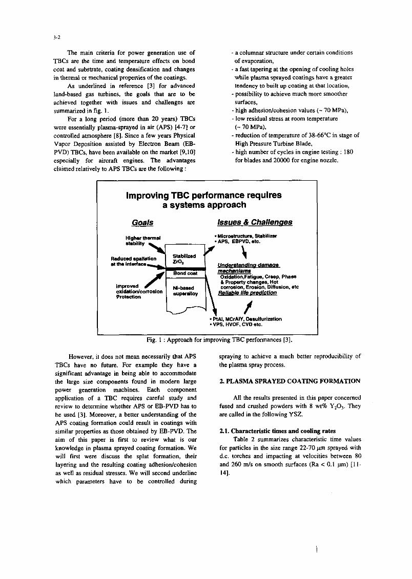
As underlined in reference [3] for advanced
land-based gas turbines, the goals that are to be
achieved together with issues and challenges arc
summarized in fig. 1.
For a long period (more than 20 years) TBCs
were essentially plasma-sprayed in air (APS) [4-71 or
controlled atmosphere [8]. Since a few years Physical
Vapor Deposition assisted by Electron Beam (EB-
PVD) TBCs. have been available on the market 19,101
especially for aircraft engines. The advantages claimed relatively to APS TBCs are the following :
_ a columnar structure under certain conditions
of evaporation,
- a fast tapering at the opening of cooling holes
while plasma sprayed coatings have a greater
tendency to built up coating at that location,
_ possibility to achieve much more smoother
s”lfaces, _ high adhesion/cohesion values (- 70 MPa),
_ low residual stress at room temperature
(- 70 MP&
-reduction of temperature of 38-66°C in stage of
High Pressure Turbine Blade,
- high number of cycles in engine testing : 180
for blades and 200CK1 for engine nozzle.
Improving TBC performance requires a systems approach
Goals issues & Challenues
Higher t-at . WicroatNct”n. stabi”zel . APS, EBPVD, mtc.
mechnnisms Oxldation.Fatigus. Creep, Phase
oxidaiionlconosion P~otectbl
* PtAI, YCrAIY. Dasulfurization . VPS. HVOF. CVD etc.
I Fig. 1 : Approach for improving TBC performances 131.
However, it does not mean necessarily that APS
TBCs have no future. For example they have a
significant advantage in being able to accommodate
the large size components found in modern large power generation machines. Each component
application of a TBC requires careful study and
review to determine whether APS or EB-PVD has to
be used [3]. Moreover. a better understanding of the
APS coating formation could result in coatings with
similar properties as those obtained by EB-PVD. The
aim of this paper is first to review what is OUT
knowledge in plasma sprayed coating formation. We will first were discuss the splat formation, their
layering and the resulting coating adhesion/cohesion
as well as residual stresses. We will second underline
which parameters have to be controlled during
spraying to achieve a much better reproducibility of
the plasma spray process.
2. PLASMA SPRAYED COATING FORMATION
All the results presented in this paper concerned
fused and crushed powders with 8 wt% Y,O,. They
arc called in the following YSZ.
2.1. Characteristic times and cooling rates Table 2 summa&z characteristic time values
for particles in the size range 22-70 pm sprayed with
d.c. torches and impacting at velocities between 80
and 260 m/s on smooth surfaces (Ra < 0.1 pm) [l l-
141.
3-3
Flattening time
tf (PS)
l-3
Starting of nucleation Solidification time Time between two Time between two
tn w 4 w impact events at the successive passes same location ti (ps) tt ws)
0.3-2.5 < 10 sol-5m 106-10’
Table 2 : Characteristic times in d.c. plasma spraying.
These various times show clearly that the
impacting particles and resulting splats will
experience very different temperature histories :
2. I. I. Single splat
Many theoretical studies have been devoted to the impact and flattening of the particles on the
substrate (see their description in [14]). All of them, except one, concern impacts on smooth surfaces.
a) Smoofh surfaces Phenomena at impact can be characterized by
the particle Web& number (We = pp d ,vpVop where pp. vp, d are the particle specific mass, impact
velocity and diameter respectively and cr? its surface
tension), and Reynolds’ number (Re = pp vp d/b
where r$ is the particle viscosity at impact). When
flattening starts, We can be rather high (up to IOOCJI)
and the flattening process is independent of particle
surface tension which has importance only when
flattening is almost completed. These theories end up
in relationships giving the particle flattening degree 5 and flattening time tf as functions of the Reynolds
number. 5 is defined as the ratio of the splat diameter
D (assumed to have a disk shape) to that of the
impacting particle d.
(=lC.Rp (1)
t, = 2 d, R$V(3 vp) (2)
K varies between 0.8 and 1.2941 while a is either 0.2 or 0. I25 or 0.167.
Typical values for a zirconia particle 30-wm in
diameter. impacting at vp = 200 m/s at a temperature
Tp = T, x 1.3. where T,,, is zirconia melting
lemperature. are for example 5 = 4.8 which
corresponds to a splat thickness e, - I.1 pm and t, -
I ps. If the impacting particle velocity increases. 5
increases while t, and e. decrease and it is the reverse
if vp decreases. The most recent theories have shown
that solidification can start before flattening is
completed [15]. Solidification depends mainly on
[14,151 the wettability of the molten material, the
thermal contact resistance Rth with the substrate, the
splat thickness e, and the thermal properties of the
substrate material. The interfacial contact resistance
characterises the real contact with the substrate or the
previously deposited layers. It can vary between 10-e
and 10-s mzK/W, the last value corresponding to a
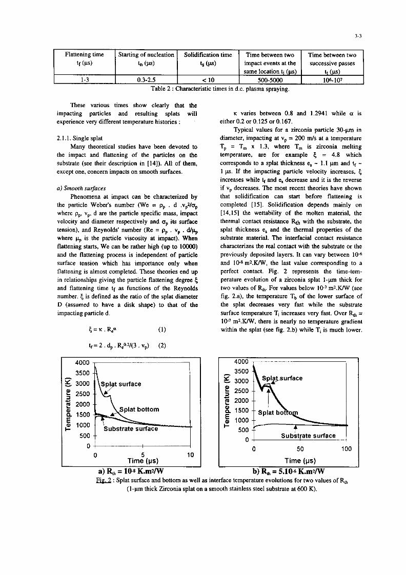
perfect contact. Fig. 2 represents the time-tem-
perature evolution of a zirconia splat I-pm thick for two values of R,,,. For values below 107 m2.KiW (see
fig. 2.a), the temperature Tb of the lower surface of
the splat decreases very fast while the substrate
surface temperature Ti increases very fast. Over R, =
10-T mZ.KN, there is nearly no temperature gradient
within the splat (see fig. 2.b) while T, is much lower.
3500
g 3000
f 2500
3 2000 i% 1500
j 1000
500
0 Time5 OJs)
a) R, = 10s K.mUW Time (ys)
b) Rh = 5.10~ K.mVW E.ig-2 : Splat surface and bottom as well as interface temperature evolutions for two values of R,
(I-ltn thick Zirconia splat on a smooth stainless steel substrate at 600 K).
3-4
In both cases the increase in splat surface temperature is due to the recalescence phenomenon. However, these results, which have been obtained by assuming a constant nucleation temperature of 2500 K and an instantaneous full contact of the whole splat, can be deeply modified if nucleation process is included in the model and the evolution of the contact surface during flattening is accounted for.
The corresponding cooling rates during the first ps are between 106 and 109 K/s. For Re < 10’ m2K/W the heat transfer rate from droplet to substrate is very high and the liquid can be cooled well below the melting point in one microsecond or less. It is therefore quite plausible that in this very short time interval, the liquid does become undercooked and nucleation of crystals is delayed until after the droplet has almost completely spread out.
As shown in fig. 2, if during flattening and just after, the cooling rate is very high, its slows down drastically for times longer than 10 to 50 us. The splat temperature tends then slowly to the mean substrate and previously deposited layer temperature T4 imposed by torch heating, previously deposited pass thickness and cooling devices.
b) Rough surfaces Only one model accounting for the substrate
roughness has been proposed [16] up to now. The roughness was schemed by cones. This model gives for the flattening degree a relationship similar to (1) but multiplied by a function depending on the cone height and the valley volume. It results, of course. in thicker splats which shape is not that of a disk. Assuming the same value of Rii, than for smooth substrates, the cooling rate will be lower due to the higher value of e,.
2. I .2. Layering splats As powder loading is rather low in plasma
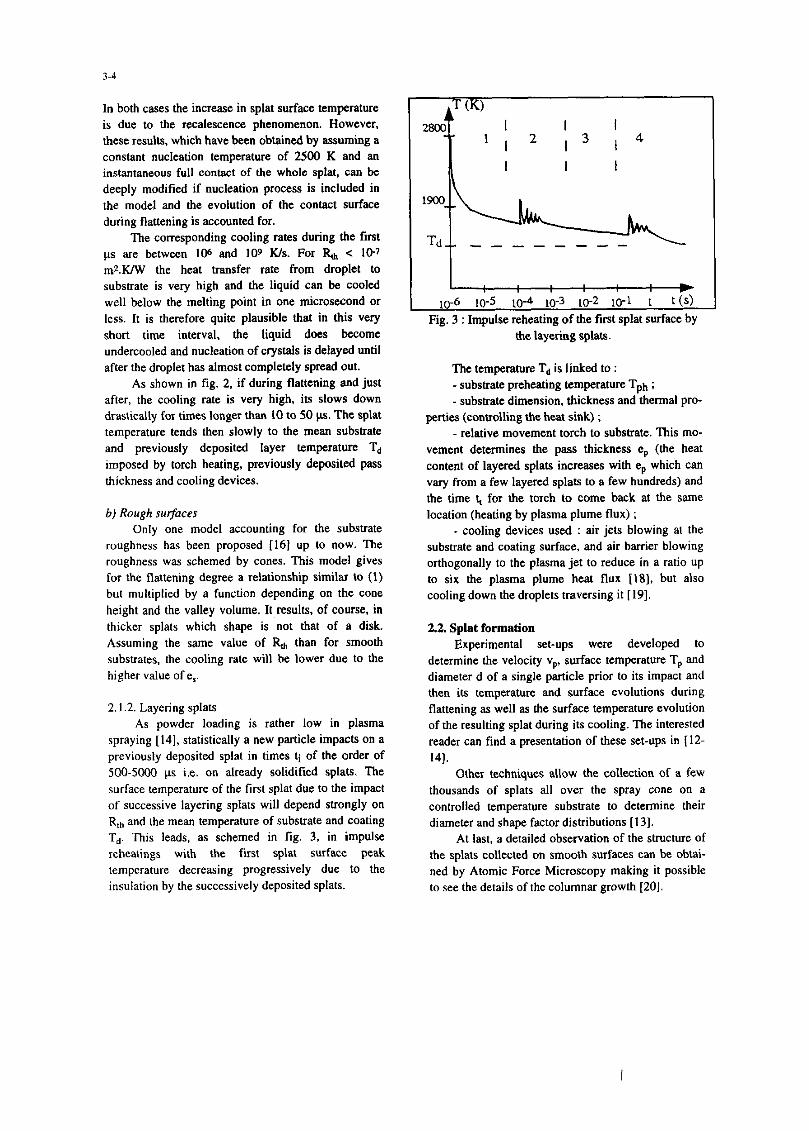
spraying [14], statistically a new particle impacts on a previously deposited splat in times ti of the order of %fJ-5ONl us i.e. on already solidified splats. The surface temperature of the first splat due to the impact of successive layering splats will depend strongly on R,,, and the mean temperature of substrate and coating T,. This leads, as schemed in fig. 3. in impulse rebeatings with the first splat surface peak temperature decreasing progressively due to the insulation by the successively deposited splats.
Td- - - - _ - _ _ -
L P 10-6 10-S 10” 10-3 lo-2 10-L 1 t (9
Fig. 3 : Impulse reheating of the first splat surface by the layering splats.
The temperature Td is linked to : - substrate preheating WIIpwatUre Tph ;
- substrate dimension, thickness and thermal pro- perties (controlling the heat sink) ;
- relative movement torch to substrate. This mo- vement determines the pass thickness eP (the heat content of layered splats increases with eP which can vary from a few layered splats to a few hundreds) and the time t, for the torch to come back at the same location (heating by plasma plume flux) ;
- cooling devices used : air jets blowing at the substrate and coating surface, and air barrier blowing orthogonally to the plasma jet to reduce in a ratio up to six the plasma plume heat flux [18], but also cooling down the droplets traversing it [19].
2.2. Splat fommtion Experimental set-ups were developed to
determine the velocity vpr surface temperature TP and diameter d of a single particle prior to its impact and then its temperature and surface evolutions during flattening as well as the surface temperature evolution of the resulting splat during its cooling. The interested reader can find a presentation of these set-ups in [12- 14).
Other techniques allow the collection of a few thousands of splats all over the spray cone on a controlled temperature substrate to determine their diameter and shape factor distributions [13].
At last, a detailed observation of the structure of the splats collected on smooth surfaces can be obtai- ned by Atomic Force Microscopy making it possible to see the details of the columnar growth [20].
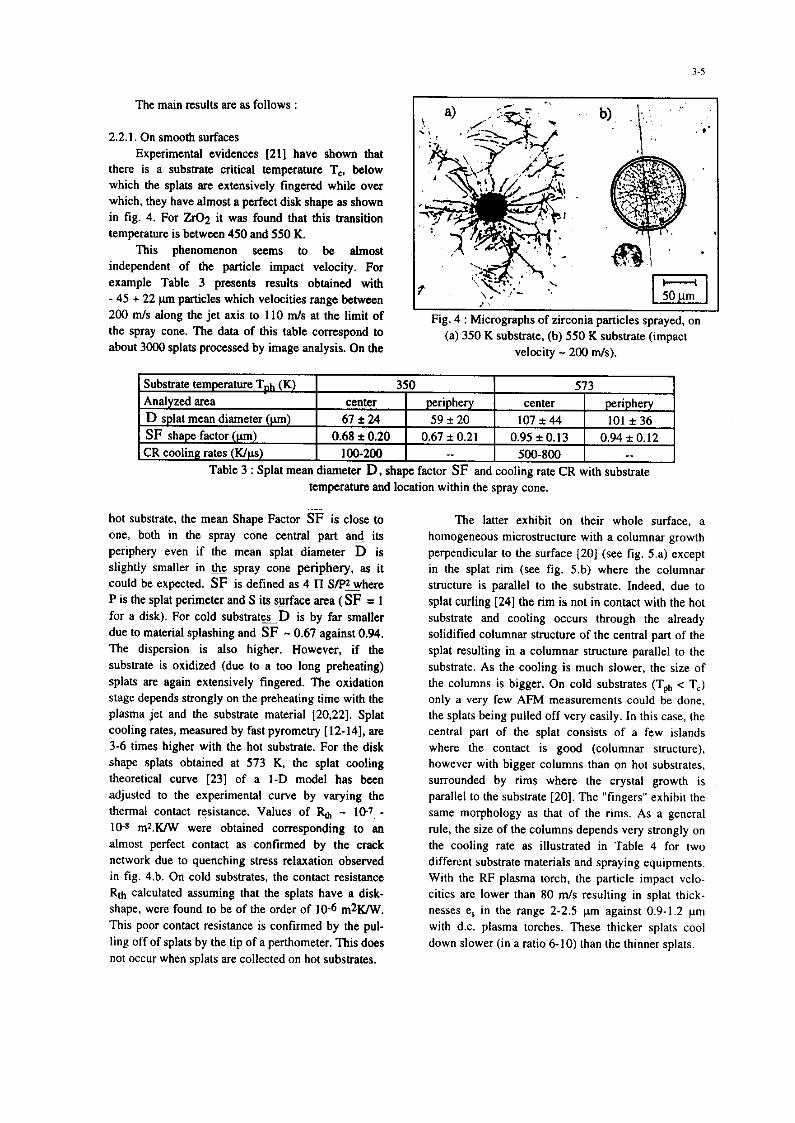
The main results are as follows :
22.1. On smooth surfaces Experimental evidences [211 have shown that
there is a substrate critical temperature Tc, below which the splats are extensively fingered while over which, they have almost a perfect disk shape as shown in fig. 4. For ZrO2 it was found that this transition temperature is between 450 and 550 K.
This phenomenon seems to be almost independent of the particle impact velocity. For example Table 3 presents results obtained with - 45 + 22 pm particles which velocities range between Zoo m/s along the jet axis to 110 m/s at the limit of the spray cone. The data of this table correspond to about 3ooO splats processed by image analysis. On the
Fig. 4 : Micrographs of zirconia particles sprayed, on (a) 350 K substrate, (b) 550 K substrate (impact
velocity - 200 m/s).
Table 3 : Splat mean diameter D, shape factor SF and cooling rate CR with substrate temperature and location within the spray cone.
hot substrate, the mean Shape Factor SF is close to one, both in the spray cone. central part and its periphery even if the mean splat diameter D is slightly smaller in & spray cone periphery. as it could be expected. SF is defined as 4 II SpAhere P is the splat perimeter and S its surface area (SF = 1 for a disk). For cold substrate~D is by far smaller due to material splashing and SF - 0.67 against 0.94. The dispersion is also higher. However, if the substrate is oxidised (due to a too long preheating) splats are again extensively fingered. The oxidation stage depends strongly on the preheating time with the plasma jet and the substrate material (20,221. Splat cooling rates, measured by fast pyrometry [12-141, are 3-6 times higher with the hot substrate.. For the disk shape splats obtained at 573 K, the splat cooling theoretical curve [23] of a 1-D model has been adjusted to the experimental curve by varying the thermal contact resistance. Values of Re, - 107, - 10-n m~.KiW were obtained corresponding to an almost perfect contact as confirmed by the crack network due to quenching stress relaxation observed in fig. 4.b. On cold substrates, the contact resistance Rth calculated assuming that the splats have a disk- shape, were found to be of the order of 10-6 m2K/W. This poor contact resistance is confirmed by the pul- ling off of splats by the tip of a penhometer. This does not occur when splats are collected on hot substrates.
The latter exhibit on their whole surface, a homogeneous microstructure with a columnar growth perpendicular to the surface [20] (see fig. 5.a) except in the splat rim (see fig. 5.b) where the columnar structure is parallel to the substrate. Indeed. due to splat curling [24] the rim is not in contact with the hot substrate and cooling occurs through the already solidified columnar structure of the central part of the splat resulting in a columnar structure parallel to the substrate. As the cooling is much slower, the size of the columns is bigger. On cold substrates (Tph < T,) only a very few AFM measurements could be done, the splats being pulled off very easily. In this case, the central part of the splat consists of a few Islands where the contact is good (columnar structure), however with bigger columns than on hot substrates, surrounded by rims where the crystal growth is parallel to the substrate [201. The “fingers” exhibu the same morphology as that of the rims. As a general rule, the size of the columns depends very strongly on the cooling rate as illustrated in Table 4 for tw different substrate. materials and spraying equipments. With the RF plasma torch, the particle impact velo- cities are lower than 80 m/s resulting in splat thick- nesses e, in the range 2-2.5 pm against 0.9-1.2 pm with d.c. plasma torches. These thicker splats cool down slower (in a ratio 6-10) than the thmner splats.
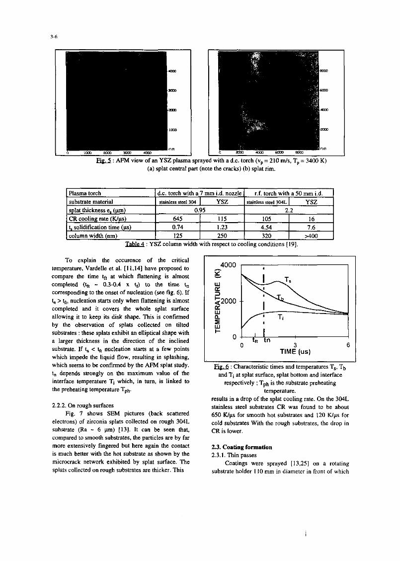
E&A : AFM view of an YSZ plasma sp #rayed with a d.c. torch (vp = 210 m/s, Tp = 3400 K) (a) splat central part (note the cracks) (b) splat rim.
Plasma torch d.c. torch with a 7 mm i.d. nozzle r.f. torch with a 50 mm id. substrate material stainless steel 304 YSZ stainless stee, 3o‘lL YSZ splat thickness e, (pm) 0.95 2.2 CR cooling rate (K&s) 645 115 105 16 f solidification time (ps) 0.74 1.23 4.54 7.6 column width (nm) 125 250 320 >4Ou
&bl& : YSZ column width with respect to cooling conditions [19].
To explain the occurence of the critical temperature, Vardelle et al. [11,14] have proposed to compare the time t* at which flattening is almost completed (k - 0.3-0.4 x t,) to the time tn corresponding to the onset of nucleation (see fig. 6). If t, > h, nucleation starts only when flattening is almost completed and it covers the whole splat surface allowing it to keep its disk shape. This is confirmed by the observation of splats collected on tilted substrates : these splats exhibit an elliptical shape with a larger thickness in the direction of the inclined substrate. If t,, < h nucleation starts at a few points which impede the liquid flow, resulting in splashing, which seems to be confirmed by the AFM splat study. t, depends strongly on the maximum value of the interface temperature Tt which, in turn, is linked to the preheating temperature Tt,t,.
I E&j : Characteristic times and temperatures T,, Tb
and Tt at splat surface. splat bottom and interface respectively ; Tph is the substrate preheating
temperature.
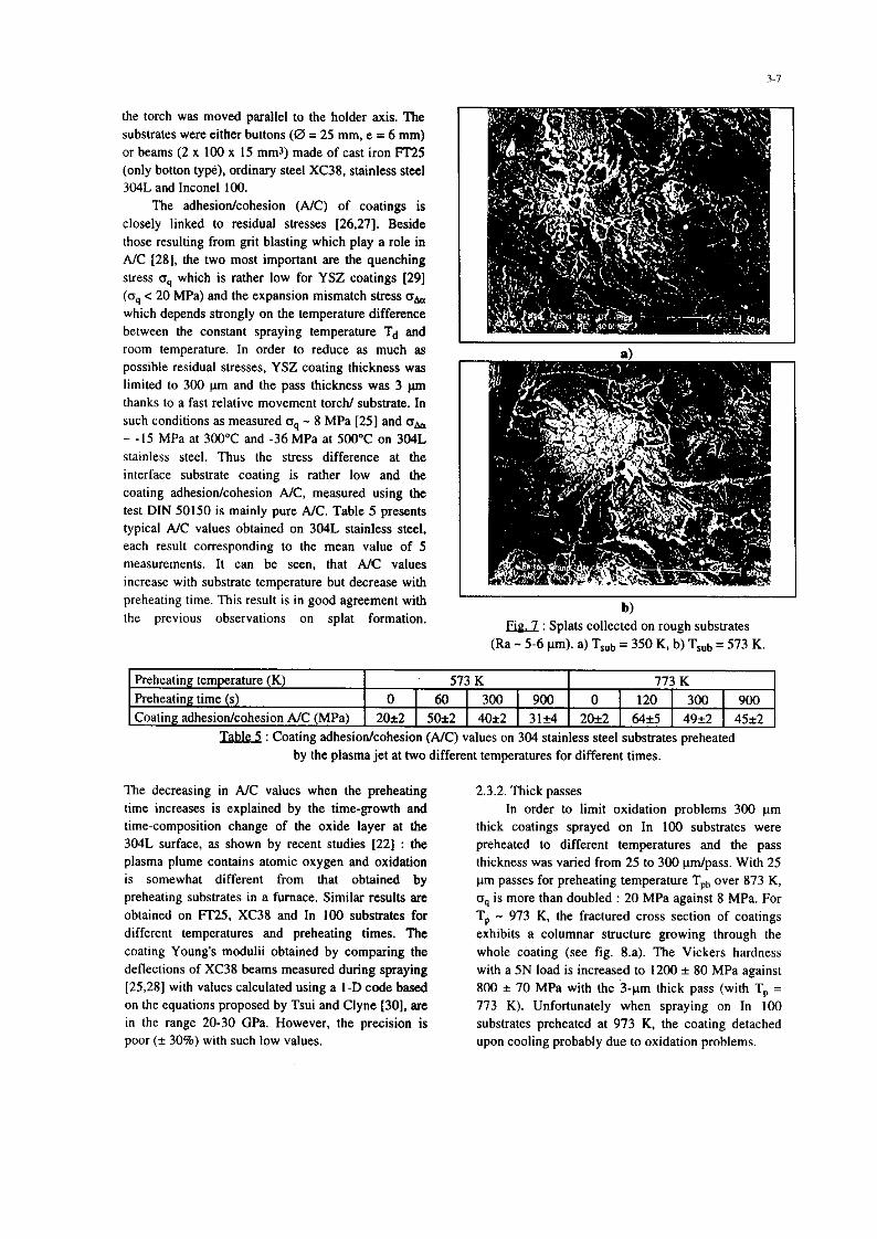
2.2.2. On rough surfaces Fig. 7 shows SEM pictures (back scattered
electrons) of zirconia splats collected on rough 304L substrate (Ra - 6 pm) [13]. It can be seen that, compared to smooth substrates, the particles are by far more extensively fingered but here again the contact is much better with the hot substrate as shown by the microcrack network exhibited by splat surface. The splats collected on rough substrates are thicker. This
results in a drop of the splat cooling rate. On the 304L stainless steel substrates CR was found to be about 650 K/p for smooth hot substrates and 120 Wps for cold substrates With the rough substrates. the drop in CR is lower.
2.3. Coating formation 2.3.1. Thin passes
Coatings were sprayed [ 13,251 on a rotating substrate holder 1 IO mm in diameter in front of which
the torch was moved parallel to the holder axis. The substrates were either buttons (0 = 25 mm, e = 6 mm) or beams (2 x 100 x 15 mm,) made of cast iron FT25 (only botton type), ordinary steel XC38. stainless steel 3O4L and Inconel 100.
The adhesion/cohesion (A/C) of coatings is closely linked to residual stresses [26,27]. Beside those resulting from grit blasting which play a role in A/C [28], the two most important are the quenching stress tsq which is rather low for YSZ coatings 1291 (oq < 20 MPa) and the expansion mismatch stress o, which depends strongly on the temperature difference between the constant spraying temperature T4 and room temperature. In order to reduce as much as posstble residual stresses, YSZ coating thickness was limited to 300 p’m and the pass thickness was 3 pm thanks to a fast relative movement torch/ substrate. In such conditions as measured IJ~ - 8 MPa [25] and oh - -15 MPa at 300°C and -36 MPa at 500°C on 3O4L stainless steel. Thus the stress difference at the interface substrate coating is rather low and the coating adhesion/cohesion A/C, measured using the test DIN 50150 is mainly pure A/C. Table 5 presents typical A/C values obtained on 304L stainless steel, each result corresponding to the mean value of 5 measurements. It can be seen. that AIC values increase with substrate temperature but decrease with preheating time. This result is in good agreement with the previous observations on splat formation.
b) &J : Splats collected on rough substrates
(Ra - 5-6 pm). a) Tsut, = 350 K, b) T,,b = 573 K.
Preheating temperature (K) 573 K 773 K Preheating time (s) 0 1 60 1 300 1 900 0 1 120 1 300 1 900 Coating adhesion/cohesion A/C (MPa) 20*2 1 5Oi2 1 40*2 1 31+4 2Oi2 1 64+5 1 49*2 1 45+2
Q&J : Coating adhesion/cohesion (A/C) values on 304 stainless steel substrates preheated by the plasma jet at two different temperatures for different times.
The decreasing in A/C values when the preheating 2.3.2. Thick passes ttme increases is explained by the time-growth and In order to limit oxidation problems 300 pm time-composition change of the oxide layer at the thick coatings sprayed on In 100 substrates were 304L surface, as shown by recent studies [22] : the preheated to different temperatures and the pass plasma plume contains atomic oxygen and oxidation thickness was varied from 25 to 300 pm/pass. With 25 is somewhat different from that obtained by pm passes for preheating temperature Tph over 873 K, preheating substrates in a furnace. Similar results are o9 is more than doubled : 20 MPa against 8 MPa. For obtained on Ff25, XC38 and In 100 substrates for Tp - 973 K. the fractured cross section of coatings different temperatures and preheating times. Tlte exhibits a columnar structure growing through the coating Young’s modulii obtained by comparing the whole coating (see fig. 8~). The Vickers hardness deflections of XC38 beams measured during spraying with a 5N load is increased to 1200 f 80 MPa against [25,28] with values calculated using a I-D code based 800 f 70 MPa with the >-pm thick pass (with T, = on the equations proposed by Tsui and Clyne [30], am 773 K). Unfortunately when spraying on In 100 in the range 20-30 GPa. However, the precision is substrates preheated at 973 K. the coating detached poor (i 30%) with such low values. upon cooling probably due to oxidation problems.
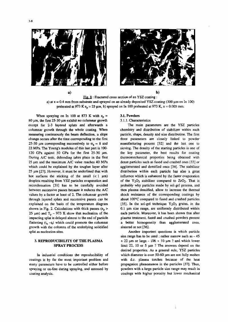
a) b) E&J : Fractured cross section of an YSZ coating :
a) at x = 0.4 mm from substrate and sprayed on an already deposited YSZ coating (300 pm on In 100) preheated at 973 K ep = 25 pm, b) sprayed on In 100 preheated at 973 K, x = 0.005 mm.
When spraying on In IO0 at 873 K with cp = 80 pm, the fust 25-30 pm exhibit no columnar growth except for 2-3 layered splats end afterwards a columnar growth through the whole coating. When measuring continuously the tam deflection, a slope change. occurs after the time corresponding to the first 25-30 pm corresponding successively to oq = 8 and 22 MPa. The Young’s modulus of this last part is IOO- 120 GPa against 50 GPa for the first 25-30 pm. During A/C tests, debonding takes place in the first 25 pm and the maximum A/C value reaches 40 MPa which could be explained by the tougher layer after 25 pm [27]. However, it must be underlined that with hot surfaces the sticking of the small (< 1 pm) droplets resulting from YSZ particles evaporation and recondensation 1311 has to be carefully avoided between successive passes because it reduces the A/C values by a factor at least of 2. The columnar growth through layered splats and successive passes can be explained on the basis of the temperature diagram shown in Fig. 2. Calculations with thick passes (e, > 25 pm) and T, - 973 K show that nucleation of the impacting splat is delayed almost to the end of particle flattening (t. -k) which could promote the columnar growth with the columns of the underlying solidified splat as nucleation sites.
3. REPRODUCIBILITY OF THE PLASMA SPRAY PROCESS
In industrial conditions the reproducibility of coatings is by far the most important problem and many parameters have to be controlled either before spraying or on-line during spraying, and assessed by coating analysis.
3.1. Powders 3.1.1. Characteristics
The main parameters are the YSZ particles chemistry and distribution of stabilizer within each particle, shape, density and size distribution. The first three parameters are closely linked to powder manufacturing process 1321 and the last one to sieving. The density of the starting particles is one of the key parameter. the best results for coating thermomechanical properties being obtained with dense particles such as fused and crushed ones [33] or agglomerated and densified ones [34]. The stabilizer distribution within each particle has also a great influence which is enhanced by the faster evaporation of the Y20) stabiliser compared to ZrOl. That is probably why particles made by sol-gel process. and then plasma densified, allow to increase the thermal shock resistance of the corresponding coatings by about 100°C compared to fused and crushed particles [35]. In the sol-gel technique YzO3 grains. in the 0.1 p size range, are uniformly distributed within each particle. Moreover. it has been shown that after plasma treatment, fused and crushed powders present a better homogeneity than agglomerated ones, sintered or not [36].
Another important questions is which particle size range has to be used : rather narrow such as - 45 + 22 wrn or large - 106 + 10 pm ? and which lower limit 22, 10 or 5 pm ? The answers depend on the desired properties. As a general rule, YSZ particles which diameter is over 50-60 pm are not fully molten with d.c. plasma torches because of the heat propagation phenomenon in the particles [37]. Thus, powders with a large particle size range may result in coatings with higher porosity but lower mechanical
resistance. For the lower limit of the particle distribution the injection problems are critical: Most of small particles, especially those below 10 pm, hardly penetrate- within the plasma jet, travel in its periphery and are sucked down fartber downstream resulting in defects in the coating when they stick to it, which is especially the case when the coating surface is kept over 773 K during spraying.
3.12. Powder injection in the plasma-jet Internal injection allows a better penetration of
the particles within the plasma jet compared to external injection 1371. However with small particles, requesting a higher carrier gas flow rate, the plasma flow perturbation is more important with internal injection [38]. The position of the injection port and its distance z from the torch axis is very critical. A variation of z of a few tenths of mm modifies deeply the particles mean trajectory. Thus. any change in the injector port location and its wear have to be checked very carefully and regularly. It is also the case of the internal wear of the injector, a rough internal surface modifying deeply the powder distribution at the injector exit compared to that obtained with a new injector with a smooth internal surface. More precisely (see section 3.2.2) the trajectory distribution of particles within the plasma jet has to be followed continuously because it controls acceleration and heating of the particles.
3.2. Plasma spray process 3.2. I. Wear of the electrodes
The arc behavior at the anode and cathode is quite different. Thor&d tungsten cathode tip wear is rather fast (- I h). It is due to the fast diffusion of thoria which increases drastically the cathode tip temperature (by about 1000 K) and induces a neck erosion below the tip which is blown up after a while [39.40]. The transition of a sharp cathode tip to a rounded one, which extremity becomes slowly and progressively wider. induces, within the first working hour. a reduction of the flow velocity of about 20% and a reduction of the arc voltage of 4 to 6% [41]. The widening of the cathode tip reduces progressively the voltage by 5-86 after 20 h. and the jet velocity by about 10%.
The arc root fluctuations (restrike mode) [41,42] which condition the arc root life time and thus the anode erosion, evolve with operation time and number of torch ignitions. This erosion is distributed in an area which length is about 1.5 x d (d being the internal diameter of the anode). The depth of the eroded area as well as the life time of the arc root increase with the operation time. Anode erosion
results in an increase of the jet instability and a decrease in jet length coupled with a decrease in coating quality. When a tungsten insert is used this erosion problem may become even more critical when tungsten particles are ejected and imbedded within coatings. Therefore, it is important to monitor the anode erosion by the statistical analysis of the voltage signal [43] or its power spectrum [44], and determine when this wear will induce poor quality coating, long before its failure.
This type of monitoring makes it possible to check rapidly a defective gun assembly resulting for example in a poor electrode catering : a non symmetrical arc attachment influencing deeply the restrike mode frequency and the voltage signal evolution.
3.2.2. Real time control The outputs that have to be set and maintained
are the particles mean temperature. velocity, trajectory and the substrate and then coating surface temperature before (preheating). during and after (cooling down) spraying. Among these parameters the most important, at least to our opinion, are the two last ones.
Substrate and coating temperature control depends strongly on the size, shape and thickness of the parts to be coated, the relative movements between the torch and the substrate and powder feed rate, linked to the pass thickness, and cooling means. If the surface temperature can be followed by IR pyrometry, the close-loop controller has to be designed according to substrate and coating heating and cooling. if possible by using simplified I-D or 2-D computer codes easily adaptable to different geometries and pass thicknesses.
The mean trajectory of the particles within the plasma jet is very sensitive to the powder inJection conditions which have to be adapted to the spraying conditions [37]. With a 1-D photodiode array, it is possible to follow continuously the hot particles distribution and, when coupling it to a laser sheet, to have simultaneously the trajectory distribution of the cold particles. The hot particles distribution is very sensitive to any variation of the injection parameters [46]. For example with ZrO2 particles (- 45 + 22 pm) a variation of the powder feed rate of 50 g can be seen and the signal intensity is multiplied by 1.9 when the powder flow rate is doubled (from I kg/h to 2 kg/h). Only 1.9 and not 2 due to the starting of the load effect. Any change of the optimum carrier gas flow rate m°Cg modifying the trajectory is immediately detected. For example a change of 10% relatively to
its optimum value induces a 10% change of the signal
amplitude and position.
Of course, it is also possible to control on line
the surface temperature of the particles prior to their
impact [47] or together the temperatures, velocities and trajectories of the particles [48]. These robust
easy-to-use optical sensors, now commercialized,
allow us, after positioning the torch in front of the
sensor head for 1 minute, to check in industrial
conditions the optimization of the spray parameters
and their time evolution. For this last point after a
certain spraying time the torch has to be positioned
again in front of the sensor head. Such devices make
them possible to determine when the load effect
becomes important, measure the time necessary
before reaching the stability of particle spraying
conditions, increase. the reproducibility of the
spraying process.
Conclusion
Plasma sprayed TBCs tbermomechanical proper-
ties depend strongly upon the contacts between splats
and substrate and layered splats. A better understanding of yttria partially
stabilized (YSZ) splat formation made it possible to
find a critical substrate preheating temperature Te, in the 400-500 K range over which these contacts are
strongly improved whatever may be the metallic
substrate or the YSZ previously deposited layers. It
seems that preheating over Tc increases the splat-
substrate interface temperature allowing delay the time t, at which nucleation starts to a value higher
than the time to achieve an almost completed
flattening. The adhesion/cohesion (A/C) of coatings
increases with preheating temperature Tph provided
the substrate oxidation is limited. With 304 L stainless
steel or In 100 substrates which oxidation resistance is
good. A/C values can reach 70 MPa with Tph = 773 K
and a preheating time with the plasma torch below
120 s.
To compete with EB-PVD coatings, conditions
have been searched to have a columnar structure
through the whole coating (up to 1 mm thick). This
structure is obtained when substrate or coating tempe-
rature reaches about 973 K. According to oxidation
problems, when spraying in air, the substrate
temperature has to be kept below this temperature and
thus the first 20 pm of the coating do not exhibit this
columnar structure but works are in progress to solve
this problem. When spraying under such conditions
the quenching stress increases drastically (from 8 to
25 MPa) with a corresponding increase of the coating
Young’s modulus (from 50 to 150 GPa). Therefore, to
control the induced residual stresses, temperature of
substrate and coating have to be monitored
continuously by adjusting the pass thickness and the cooling devices to the coated part dimensions with the
help of simplified 1-D or 2-D computer codes.
At last, to improve coatings reproducibility, strongly linked to the molten state and velocity of
impacting particles, a rather simple set-up has been
developed giving in real time the trajectory
distribution of hot particles within the plasma jet and
allowing to check any change in powder flow rate,
carrier gas injection flow rate, injector wear...
Compared to commercial set-ups following particle
velocity, surface temperature and flux density it is by far much simpler and seems to be as efficient. The
erosion of the torch nozzle has also to be followed by
analyzing the voltage fluctuations which vary
drastically when conditions are reached where coating
quality is affected and allows also the detection of
defective gun assembly.
Nomenclature A/C adhesion/cohesion (MPa)
APS Atmospheric Plasma Spraying
CR cooling rate (Wps)
D splat mean diameter (pm)
d particle diameter (pm)
eP pass thickness (pm)
es splat thickness (lm)
R, Reynold’s number (dimensionless)
Rth thermal contact resistance (&K/W)
SF splat shape factor (dimensionless)
Tb temperature of the lower surface of the splat
W)
Td equilibrium temperature reached by coating
upon spraying (K)
9 interfacial contact between splat and substrate
W)
T”l particle melting temperature (K)
TP particle impact temperature (K)
Tph substrate preheating temperature (K)
tf flattening time (ps)
tft time at which flattening is almost completed
W)
ti time between two successive impacts (ps)
tn time at which nucleation starts (ps)
1s time at which solidification is completed (ps)
h time between two successive passes (ps)
“P particle velocity at impact (m/s)
W, Web&s number (dimensionless)
p’p molten particle viscosity (kg/m.s)
pP particle specific mass (kglm3)
UP molten particlc surface tension (N/m)
s flattening degree (5 = D/d)
References
[I] W.J. Brindley, Journal of Themxd Spray Technology I(4) (1996) 379-380.
[Z] W.A. Nelson and R.M. Orenstein, Journal of Thermal Spray Technology h (2) (1997) 176- 180.
(31 W.P. Parks, E.E. Hoffman, W.Y. Lee and LG. Wright, Journal of Thermal Spray Technology 6 (2) (1997) 187-198.
141 D.W. WOTtlNi”. B.A. Nagaraj and E.L. Duderstadt, Mater. Sci. Eng. A&l (1989) 443-440.
[5] R.A. Miller, Surf. Coat. Technol. ZQ (1987) l- II.
[6] B.C. Wu and E. Chang. Thin Solid Films ll2 (1989) 185-196.
[7] M. Yoshida. K. Abe, T. Aranami and Y. Harada, Journal of Thermal Spray Technology I (3) (1996) 259-268.
[S] S. Sodevka. M. Sazaki and K. Ueno. Journal of Thermal Spray Technology 5 (3) (1996) 277- 282.
[9] D.V. Rigney, R. Vignie, D.I. Wortman and D.W. Skelly, Journal of Thermal Spray Technology 6 (2) (1997) 167-175.
[IO] A. Maricocchi, A. Batz and D. Wortman, Journal of Thermal Spray Technology 6 (2) (1997) 193-198.
[I I] A. Vardelle, N.J. Them% B. Dussoubs. M. Vardelle and P. Fauchais. Transport and chemical rate phenomena in plasma sprays, J. of High Temp. Material Processes 4 (1997). to be published.
[I21 P. Fauchais, M. Vardelle, A. Vardelle, L. Bianchi and AC. Ltger, Plasma Chemistry Plasma Processing .I.6 (1) (1996) 99%126s.
[ 131 L. Bianchi, A.C. L&w. M. Vardelle. A. Vardelle and P. Fauchais, Plasma Sprayed zirconia splat formation and cooling, accepted in Thin Solid Films (1997).
1141 P. Fauchais, A.C. LBger. M. Vardelle and A. Vardelle, Formation of plasma-sprayed oxide coatings, in Proc. of J. Szekely Memorial Symp. on Materials Processing (Pub.) TMS (1997).
[IS] M. Pasandideh-Fard, Y.M. Quiav, S. Chander and I. Mostaghimi, Physics of Fluids B (1996) 650-659.
1161 H. Fukanama. in Thermal Spray : Practical Solutions for Engineering Problems (ed.) C.C. Berndt and H. Herman. (Pub.) ASM Int. OH, USA (1996) 647.656.
[ 171 S. Kuroda, T. Dendo and S. Kitahara, Journal of ‘Thermal Spray Technology, 4 (I) (1995) 75-84.
1181 F. Monerie-Moulin, F. Gitzhofer. P. Fauchais, M. Boulos and A. Vardelle. J. of High Temp. Chem. Processes l(3) (1992) 249-257.
[19] A. Haddadi, F. Nardou, A. Grimaud and P. Fauchais, in Advances in Thermal Spray Science and Technology (eds.) CC. Berndt and S. Sampath (Pub.) ASM Int. OH, USA (1995) 249-254.
[20] L. Bianchi, A. Denoirjean. F. Blein and P. Fattchais, Thin Solid Films 2pe (1997) 125. 135.
[21] M. Fukumato. S. Katoh and I. Okane. Proc. of 14’ ITSC (Ed.) A. Ohmori (Pub.) High Temp. Sot. of Japan, Osaka, Japan (1995) 353-358.
[22] A. Denoirjean. A. Grimattd, P. Fauchais, J. Pech and B. Hatmoyer, Influence. of substrate oxidation on alumina splats in plasma spraying, hoc. of United Thermal Spray Conf., Indiannapolis 15-18 Sept. (1997), (Pub.) ASM Int. OH, USA.
[23] A. Vardelle, M. Vardelle. P. Fauchais and D. Gobin, NATO Series E : Applied Science 282 (1995) 95-121.
1241 M. Batagnoli, M. Marchese and G. Jaccuci, J. of Thermal Spray Technology 4 (I) (1995) 41-49.
[25] AC. Ldger. PhD Thesis (in French), Univ. of Limoges. France, March 12’ (1997).
[26] T.W. Clyne and SC. Gill, J. of Thermal Spray Technology i(4) (1996) 401-418.
1271 Y.C. Tsui and T.W. Clyne, see [ 161, (1996) 275- 284.
[28] M. Mellali, P. Fauchais and A. Grimaud, Surf. and Coatings Technol. 81 (1996) 275-286.
[29] A.C. uger. A. Grimaud, P. Fauchais and C. Catteau, see [16] (1996) 891.896.
[30] Y.C. Tsui and T.W. Clyne, An analytical model for predicting residual stresses in progressively deposited coatings. Part 1 : Plasma geometry, submitted to Thin Solid Films Dec. (1996).
[31] K.A. Gross, I. Tikkanen. J. Keskinen. P. Fauchais, M. Vardelle and A. Grimaud. Vaporization and ultrafine particle generation during the plasma spraying process, to be published in United Thermal Spray Conference, Indiannapolis Sept. (1997) (Pub.) ASM Int. OH, USA.
132) H. Eschnauer, Thin Solid Films. B (1980) I-17. [33] F. Gitzhofer. A. Vardelle, M. Vardelle and
P. Fauchais. Materials Science and Eng. Al47 (1991) 107.120.
[34] A. Denoirjean. A. Vardelle. C. Martin, P. Fauchais, T. Cosack. E. Lugsheier, I. Rass, P. Chandler, R. McIntyre and H.L. Heijen, in Thermal Spray : Int. Advances in Coatings
3-12
Technology (Pub.) ASM Int. OH, USA, (1992) 967-982.
[35] D. Bernard, PhD’s thesis, Univ. of Limoges, June 25 (1990).
f36] 8. Kolman. I. Forman. J. Dubsky and P.Chraska, Mikmchim. Acta ~ (1994) 335-342.
[37] M. Vardelle, A. Vardelle and P. Fauchais, J. of Thermal Spray Technology 1 (2) (1992) 117- 128.
[38] B. Dussoubs, A. Vardelle, M. Vardelle, P. Fauchais and N.J. Themelis, 13’ Int. Symp. on Plasma Chem. 5 (1997) 2056-2061 (xl.) Prof. C.K. WU, Institute of Mechanics, Chinese Academy of Sciences, Beijing 100080. China.
[39] X. Zhou and J. Heberlein, Plasma Chem. Plasma Rot. 16 (1) (1996) 299S-2448.
1401 X. Zhou, B. Ding and J. Heberlein, IEEE Trans. Components Pkg. and Mfg. Tech. fi (3) (1996) 320-328.
[41] P. Fauchais, J.F. Coudert and M. Vardelle, Transient phenomena in plasma torches and for plasma sprayed coating generation, accepted in J. de Physique III.
[42] J.F. Coudert, M.P. Planche and P. Fauchais, Plasma Chem. Plasma Proc. 16 (1) (1996) 2llS- 2288.
[43] M.P. Planche, PhD’s thesis (in French), Univ. of Limoges, France (1995).
[44] Z. Duan. L. Beall, M.P. Planche, 1. Heberlein and E. Pfender, Arc voltage fluctuations as an indication of spray torch anode condition, to be published in proc. of UTSC 97, (Pub.) ASM Int. OH, USA.
[45] K.I. Li, M. Vardelle and P. Fauchais, see [19] (1995) 59-66.
[46] M. Vardelle, A.C. Lbger, A. Vardelle and P. Fauchais, Influence of the variation of plasma torch parameters on particle melting and soliditication, to be published in Proc. of UTSC 97, (Pub.) ASM Int. OH, USA.
[47] W.D. Swank, J.R. Fincke and D.C. Haggard, see [I91 (1995) 111-116.
[481 C. Moreau, P. Gougeon, A. Burgess and D. Ross, see [19] (1995) 141-147.