Embed Size (px)
Citation preview
International Journal Of Computational Engineering Research (ijceronline.com) Vol. 3 Issue. 1
||Issn 2250-3005(online)|| ||January || 2013 Page 195
Behaviour of Reinforced Concrete Slab Subjected To Fire
Mr. C Sangluaia 1, Mr. M K Haridharan
2, Dr. C Natarajan
3, Dr. A. Rajaraman
4
1 M Tech Scholar, National Institute of Technology, Thiruchirappalli, India ,
2PhD Scholar, Nat ional Institute of Technology, Thiruchirappalli, India,
3Professor, National Institute of Technology, Thiruchirappalli, India
4Former Visit ing Professor, Indian Institute of Technology, Madras, India
Abstract The behavior of reinforced concrete slab exposed to fire is presented. Two stages of analysis is carried out using
Fin ite Element package ABAQUS to find thermal response of structural members namely thermal analysis and structural
analysis. In the first step, the distribution of the temperature over the depth during fire is dete rmined. In the next step, the
mechanical analysis is made in which these distributions are used as the temperature loads. The responses of structure depend
on the type of concrete and the interactions of structural members. The RCC slab were modeled to sho w the role of slab
thickness, percentage of reinforcement, width of slab and different boundary condition when expose to fire loading. Effects
for both materials in RCC slab at elevated temperatures are also evaluated.
Keywords: ABAQUS, Concrete, Fire, Floor slabs, Modeling, Structural response, Thermal response.
1. Introduction Fire is considered one of the most serious potential risks for buildings and structures. But concrete is generally
considered to have an acceptable resistance to fire in comparis on with other construction materials such as wood or steel.
When concrete remains exposed for long time to high temperatures, mechanical losses of its properties take place. Laboratory
experiences show that in case of concrete not protected the mechanical properties decrease drastically for temperatures above
300ºC. They are attributed to the microstructure transformat ions occurring in cement paste and aggregates, and the volume
changes induced by thermal stresses. After fire the assessment of deterioration of the structure is needed in order to identify
the level of damage induced by the chemical transformation and the cracking, both contributing to losses in mechanical
strength.The behaviour of structures exposed to fire is usually described in terms of th e concept of fire resistance, which is
the period of time under exposure to a standard fire time-temperature curve at which some prescribed form of limit ing
behaviour occurs. In real buildings structural elements form part of a continuous assembly, and build ing fires often remain
localized, with the fire-affected region of the structure receiving significant restraint from cooler areas surrounding it. The
real behaviour of these structural elements can therefore be very different from that ind icated by stan dard furnace tests.
When concrete is under fire, it usually causes a build-up of pressure within the concrete after exceeding 1000C.When the
temperature reaches about 400 °C, the calcium hydroxide in the cement will begin to dehydrate, generating more wate r
vapour and also bringing about a significant reduction in the phys ical strength of the material [1]. The material behavior
during heating is nonlinear itself according to its deterioration with temperature [ 2]. Most real fires heat the floor and beams
from below, leading to a regime in which temperature differentials develop between the upper and lower surfaces. These
differentials lead to thermally induced bending or thermal bowing, which can increase deflections. High temperatures will
result in loss of strength (both yield and ultimate strengths) and stiffness (moduli o f elasticity) [3]. Whilst material
degradation is the key phenomenon in determinate structures under fire, for highly redundant structures the single most
important factor is the effect of thermal expansion [3].
2. Mechanical Behaviour of The Constituent Materials 2.1 General
Constitutive laws are used to define the stress–strain characteristics of a material. The accuracy of the analysis is
dependent on the constitutive laws used to define the mechanical behaviour. In materials such as concrete, structural steel and
reinforcing steel, profiled steel sheeting and shear connectors, the constitutive laws are represented by the stress –strain
relationships of the materials. In this paper, the mechanical behaviour at ambient and elevated temperatures is considered.
When elevated temperature is involved, the main properties required to carry out an accurate calculation of the temperature
distribution in a composite cross-section are the specific heat, thermal expansion and thermal conductivity.
2.2 Thermal properties of concrete: An important design consideration for concrete includes the effects of fire. The
behaviour of concrete slabs subjected to fire conditions is complex. In a fully developed fire, to prevent fire spread to the
upper floors, the slab has to carry and withstand the applied loads and prevent collapse during and after the fire. The effec t of
fire, which is not generally considered in typical structural design practice, involves the thermal conductivity, specific heat
International Journal Of Computational Engineering Research (ijceronline.com) Vol. 3 Issue. 1
||Issn 2250-3005(online)|| ||January || 2013 Page 196
and high thermal expansion of the concrete. This will cause the surrounding structure to respond against these effects and
generate compressive forces in the heated concrete slab.
2.2.1 Thermal conductivi ty. Thermal conductivity is the capability of a material to conduct heat, and is defined as the ratio
of heat flux to the temperature gradient. It represents the uniform flow of heat through concrete of unit thickness over a un it
area subjected to a unit temperature difference between the two opposite faces [6]. The thermal conductivity of siliceous
aggregate concrete as represented in Eurocode 2, Brit ish Standards Institution in section 3.3.3 is shown in Fig 1.
2.2.2 Specific heat. The specific heat of a material is the amount of heat per unit mass which is required to change the
temperature of the material by a degree. The specific heat of concrete with siliceous aggregates as a function of temperature
according to Eurocode2, Brit ish Standards Institution in section 3.3.2 is shown in Fig. 2.
Fig. 1 Thermal conductivity of concrete, EC2 [4]
Fig. 2 Specific heat of concrete, EC2 [4]
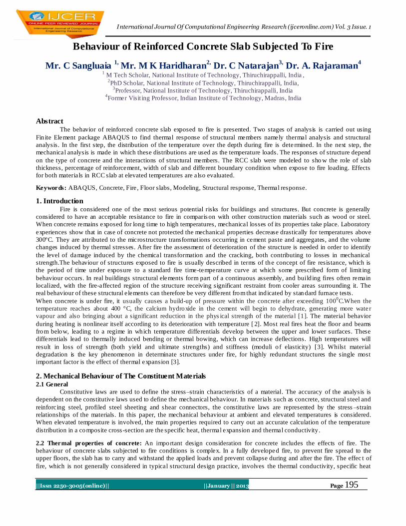
2.2.3 Thermal expansion. Due to its isotropic nature, concrete exhib its thermal expansion when it is subjected to a
temperature change. Cracking occurs when stresses develop in concrete structures due to non -uniform thermal expansion.
The thermal expansion of concrete with siliceous aggregates expressed as a function of temperature according to Eurocode 2,
British Standards Institution in section 3.3.1 is shown in Fig. 3
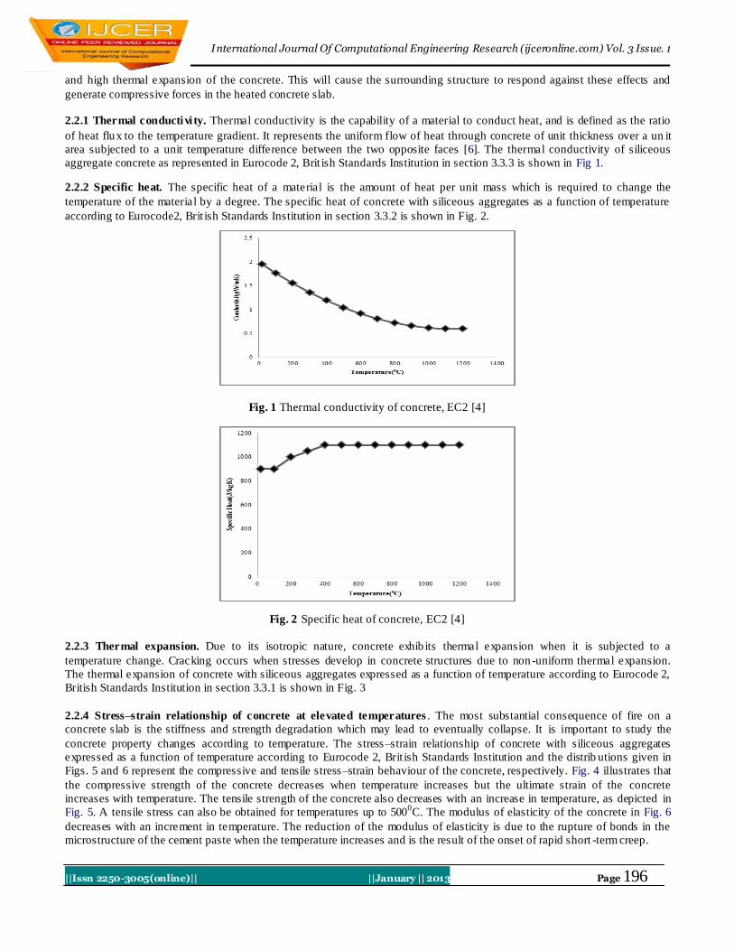
2.2.4 Stress–strain relationship of concrete at elevated temperatures . The most substantial consequence of fire on a
concrete slab is the stiffness and strength degradation which may lead to eventually collapse. It is important to study the
concrete property changes according to temperature. The stress–strain relationship of concrete with siliceous aggregates
expressed as a function of temperature according to Eurocode 2, Brit ish Standards Institution and the distrib utions given in
Figs. 5 and 6 represent the compressive and tensile stress–strain behaviour of the concrete, respectively. Fig. 4 illustrates that
the compressive strength of the concrete decreases when temperature increases but the ultimate strain of the concrete
increases with temperature. The tensile strength of the concrete also decreases with an increase in temperature, as depicted in
Fig. 5. A tensile stress can also be obtained for temperatures up to 5000C. The modulus of elasticity of the concrete in Fig. 6
decreases with an increment in temperature. The reduction of the modulus of elasticity is due to the rupture of bonds in the
microstructure of the cement paste when the temperature increases and is the result of the onset of rapid short -term creep.
International Journal Of Computational Engineering Research (ijceronline.com) Vol. 3 Issue. 1
||Issn 2250-3005(online)|| ||January || 2013 Page 197
Fig. 3 Concrete thermal expansion, EC2 [4]
0
5
10
15
20
25
30
35
0 0.01 0.02 0.03 0.04 0.05
Str
ess (
N/m
m2)
Strain
1000 Degree Celcius
20 Degree Celcius
100 Degree Celcius
200 Degree Celcius
300 Degree Celcius
400 Degree Celcius
500 Degree Celcius
600 Degree Celcius
700 Degree Celcius
800 Degree Celcius
900 Degree Celcius
Fig. 4 Compressive stress–strain relationship at elevated temperature for concrete, EC2
Fig. 5 Tensile stress–strain relationship at elevated temperature for concrete, EC2
0
5000
10000
15000
20000
25000
0 200 400 600 800 1000 1200
Ela
sti
c M
od
ulu
s(N
/mm
2)
Temperature(0C)
Fig. 6 Modulus of elasticity of structural concrete at elevated temperatures, EC2.
International Journal Of Computational Engineering Research (ijceronline.com) Vol. 3 Issue. 1
||Issn 2250-3005(online)|| ||January || 2013 Page 198
2.3 Thermal properties of steel
The stress–strain characteristics of reinforcing steel are essentially similar to structural steel. Their behav iour is
initially elastic after which yield ing and strain hardening develops. A piecewise linear approach was found to be sufficiently
accurate to represent the stress–strain relationship. Moreover, these curves are utilized in the model when the stress –strain
data is not available. The stress–strain relationship for structural steel is represented as a simple elastic–plastic model with
strain hardening. The mechanical behaviour for both compression and tension is assumed to be similar. Fig. 10 represents the
stress–strain relationship for steel. The effects of thermal conductivity, specific heat and high thermal expansion of the
reinforcing steel are considered when the temperature changes.
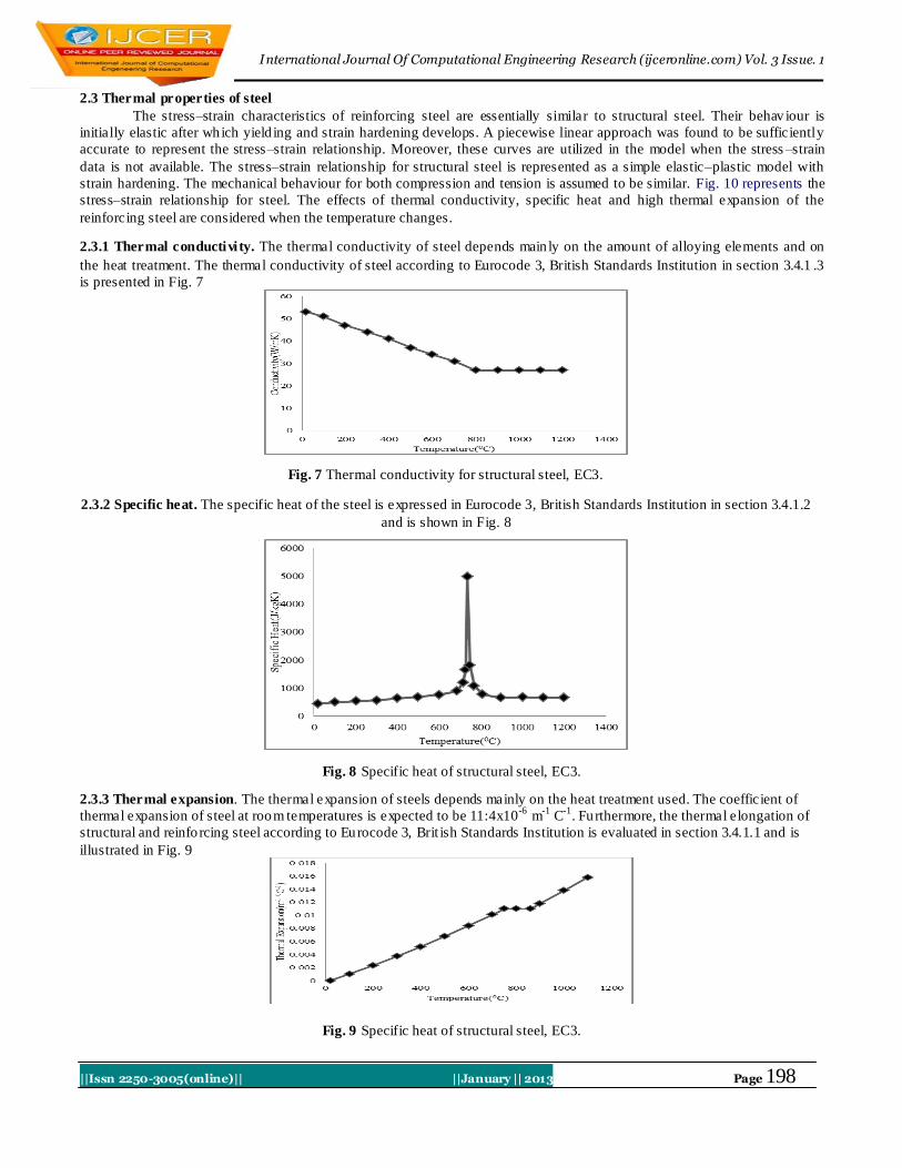
2.3.1 Thermal conductivi ty. The thermal conductivity of steel depends main ly on the amount of alloying elements and on
the heat treatment. The thermal conductivity of steel according to Eurocode 3, British Standards Institution in section 3.4.1 .3
is presented in Fig. 7
Fig. 7 Thermal conductivity for structural steel, EC3.
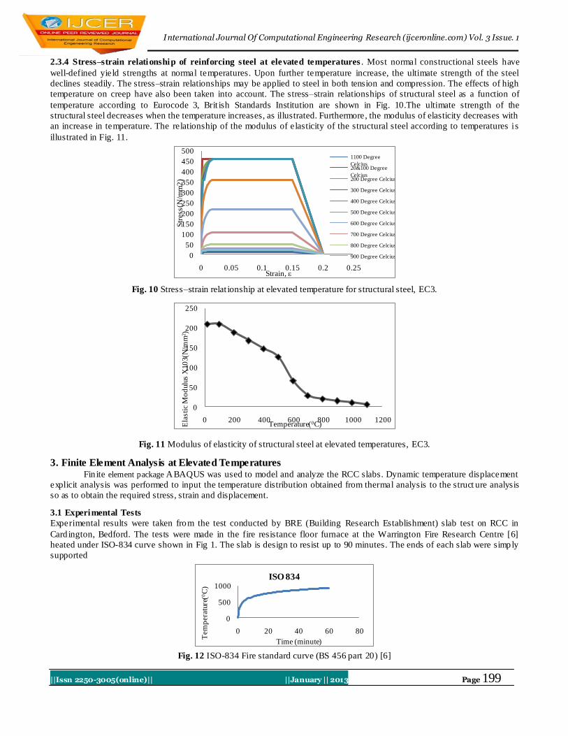
2.3.2 Specific heat. The specific heat of the steel is expressed in Eurocode 3, British Standards Institution in section 3.4.1.2
and is shown in Fig. 8
Fig. 8 Specific heat of structural steel, EC3.
2.3.3 Thermal expansion. The thermal expansion of steels depends mainly on the heat treatment used. The coefficient of
thermal expansion of steel at room temperatures is expected to be 11:4x10⁻⁶
m-1
C-1
. Furthermore, the thermal elongation of
structural and reinforcing steel according to Eurocode 3, Brit ish Standards Institution is evaluated in section 3.4.1.1 and is
illustrated in Fig. 9
Fig. 9 Specific heat of structural steel, EC3.
International Journal Of Computational Engineering Research (ijceronline.com) Vol. 3 Issue. 1
||Issn 2250-3005(online)|| ||January || 2013 Page 199
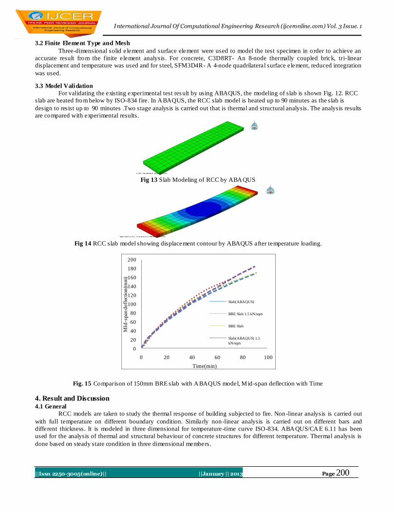
2.3.4 Stress–strain relationship of reinforcing steel at elevated temperatures . Most normal constructional steels have
well-defined yield strengths at normal temperatures. Upon further temperature increase, the ultimate strength of the steel
declines steadily. The stress–strain relationships may be applied to steel in both tension and compression. The effects of high
temperature on creep have also been taken into account. The stress–strain relationships of structural steel as a function of
temperature according to Eurocode 3, Brit ish Standards Institution are shown in Fig. 10.The ultimate strength of the
structural steel decreases when the temperature increases, as illustrated. Furthermore, the modulus of elasticity decreases with
an increase in temperature. The relationship of the modulus of elasticity of the structural steel according to temperatures is
illustrated in Fig. 11.
0
50
100
150
200
250
300
350
400
450
500
0 0.05 0.1 0.15 0.2 0.25
Str
ess(
N/m
m2
)
Strain, ε
1100 Degree
Celcius20&100 Degree
Celcius200 Degree Celcius
300 Degree Celcius
400 Degree Celcius
500 Degree Celcius
600 Degree Celcius
700 Degree Celcius
800 Degree Celcius
900 Degree Celcius
Fig. 10 Stress–strain relat ionship at elevated temperature for structural steel, EC3.
0
50
100
150
200
250
0 200 400 600 800 1000 1200
Ela
sti
c M
od
ulu
s X
10
3(N
/mm
2 )
Temperature(0C)
Fig. 11 Modulus of elasticity of structural steel at elevated temperatures, EC3.
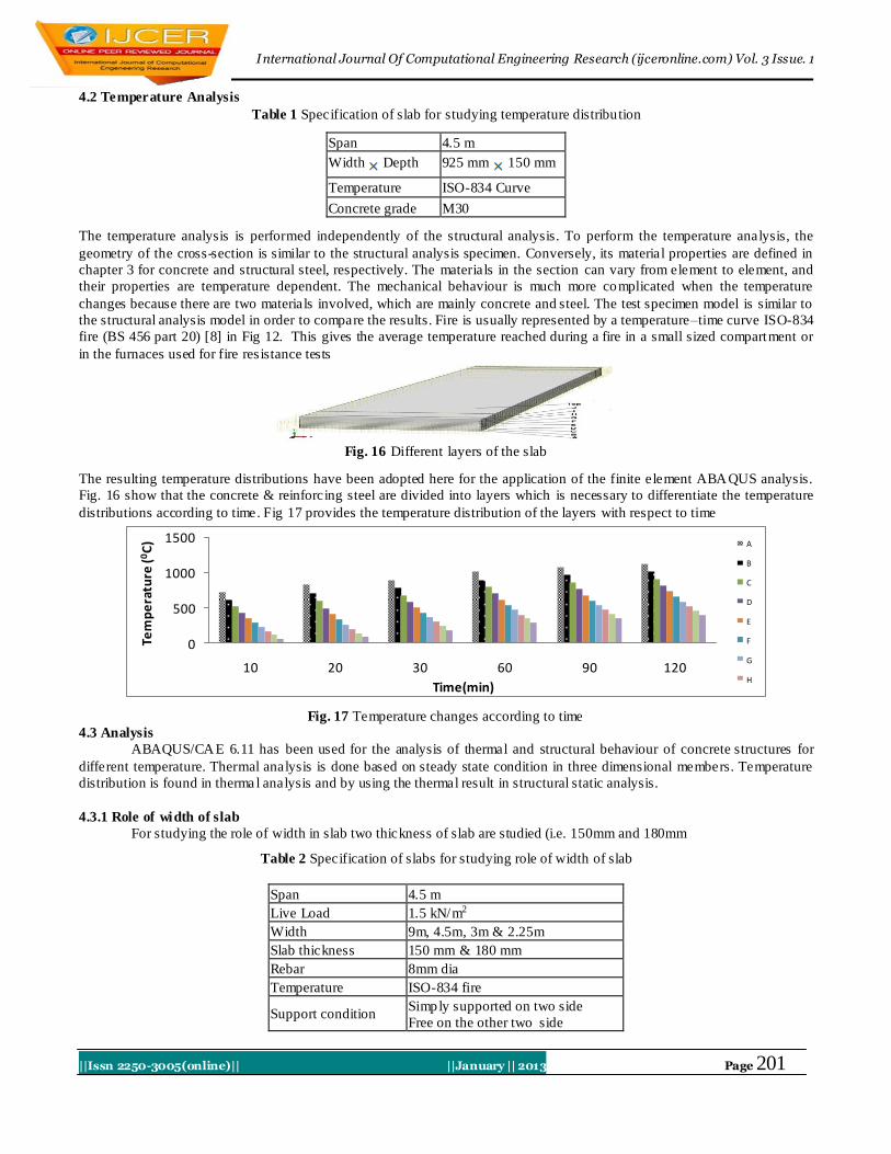
3. Finite Element Analysis at Elevated Temperatures Fin ite element package ABAQUS was used to model and analyze the RCC slabs. Dynamic temperature displacement
explicit analysis was performed to input the temperature distribution obtained from thermal analysis to the struct ure analysis
so as to obtain the required stress, strain and displacement.
3.1 Experimental Tests
Experimental results were taken from the test conducted by BRE (Building Research Establishment) slab test on RCC in
Card ington, Bedford. The tests were made in the fire resistance floor furnace at the Warrington Fire Research Centre [6]
heated under ISO-834 curve shown in Fig 1. The slab is design to resist up to 90 minutes. The ends of each slab were simply
supported
0
500
1000
0 20 40 60 80
Tem
pera
ture
(0C
)
Time (minute)
ISO 834
Fig. 12 ISO-834 Fire standard curve (BS 456 part 20) [6]
International Journal Of Computational Engineering Research (ijceronline.com) Vol. 3 Issue. 1
||Issn 2250-3005(online)|| ||January || 2013 Page 200
3.2 Finite Element Type and Mesh
Three-dimensional solid element and surface element were used to model the test specimen in o rder to achieve an
accurate result from the finite element analysis. For concrete, C3D8RT- An 8-node thermally coupled brick, tri-linear
displacement and temperature was used and for steel, SFM3D4R- A 4-node quadrilateral surface element, reduced integration
was used.
3.3 Model Validation
For validating the existing experimental test res ult by using ABAQUS, the modeling of slab is shown Fig. 12. RCC
slab are heated from below by ISO-834 fire. In ABAQUS, the RCC slab model is heated up to 90 minutes as the slab is
design to resist up to 90 minutes .Two stage analysis is carried out that is thermal and structural analysis. The analysis results
are compared with experimental results.
Fig 13 Slab Modeling of RCC by ABAQUS
Fig 14 RCC slab model showing displacement contour by ABAQUS after temperature loading.
0
20
40
60
80
100
120
140
160
180
200
0 20 40 60 80 100
MId
-span
def
lect
ion
(mm
)
Time(min)
Slab(ABAQUS)
BRE Slab 1.5 kN/sqm
BRE Slab
Slab(ABAQUS) 1.5
kN/sqm
Fig. 15 Comparison of 150mm BRE slab with ABAQUS model, Mid-span deflection with Time
4. Result and Discussion 4.1 General
RCC models are taken to study the thermal response of building subjected to fire. Non -linear analysis is carried out
with full temperature on different boundary condition. Similarly non-linear analysis is carried out on different bars and
different thickness. It is modeled in three dimensional for temperature-time curve ISO-834. ABAQUS/CAE 6.11 has been
used for the analysis of thermal and structural behaviour of concrete structures for different temperature. Thermal analysis is
done based on steady state condition in three dimensional members.
International Journal Of Computational Engineering Research (ijceronline.com) Vol. 3 Issue. 1
||Issn 2250-3005(online)|| ||January || 2013 Page 201
4.2 Temperature Analysis
Table 1 Specification of slab for studying temperature distribution
Span 4.5 m
Width Depth 925 mm 150 mm
Temperature ISO-834 Curve
Concrete grade M30
The temperature analysis is performed independently of the structural analysis. To perform the temperature analysis, the
geometry of the cross-section is similar to the structural analysis specimen. Conversely, its material properties are defined in
chapter 3 for concrete and structural steel, respectively. The materials in the section can vary from element to element, and
their properties are temperature dependent. The mechanical behaviour is much more complicated when the temperature
changes because there are two materials involved, which are mainly concrete and steel. The test specimen model is similar to
the structural analysis model in order to compare the results. Fire is usually represented by a temperature–time curve ISO-834
fire (BS 456 part 20) [8] in Fig 12. This gives the average temperature reached during a fire in a small sized compartment or
in the furnaces used for fire res istance tests
Fig. 16 Different layers of the slab
The resulting temperature distributions have been adopted here for the application of the finite element ABAQUS analysis.
Fig. 16 show that the concrete & reinforcing steel are divided into layers which is necessary to differentiate the temperature
distributions according to time. Fig 17 provides the temperature distribution of the layers with respect to time
0
500
1000
1500
10 20 30 60 90 120
Tem
pe
ratu
re (0
C)
Time(min)
A
B
C
D
E
F
G
H
Fig. 17 Temperature changes according to time
4.3 Analysis
ABAQUS/CAE 6.11 has been used for the analysis of thermal and structural behaviour of concrete structures for
different temperature. Thermal analysis is done based on steady state condition in three dimensional members. Temperature
distribution is found in therma l analysis and by using the thermal result in structural static analysis.
4.3.1 Role of width of slab
For studying the role of width in slab two thickness of slab are studied (i.e. 150mm and 180mm
Table 2 Specification of slabs for studying role of width of slab
Span 4.5 m
Live Load 1.5 kN/m2
Width 9m, 4.5m, 3m & 2.25m
Slab thickness 150 mm & 180 mm
Rebar 8mm dia
Temperature ISO-834 fire
Support condition Simply supported on two side
Free on the other two side
International Journal Of Computational Engineering Research (ijceronline.com) Vol. 3 Issue. 1
||Issn 2250-3005(online)|| ||January || 2013 Page 202
0
50
100
150
200
250
0 20 40 60 80 100M
id-S
pa
n d
isp
lacem
en
t(m
m)
Time(min)
2.25m Width
9m Width
4.5m Width
3m Width
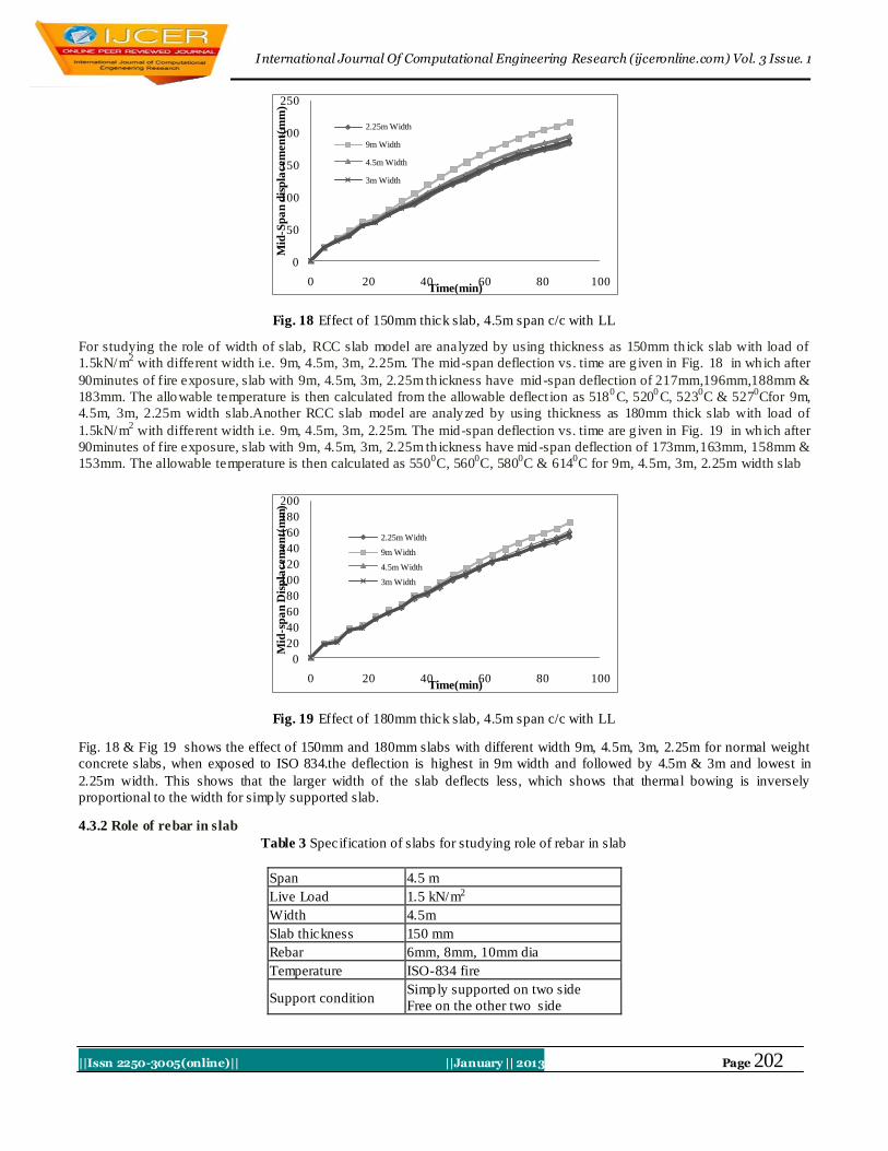
Fig. 18 Effect of 150mm thick slab, 4.5m span c/c with LL
For studying the role of width of slab, RCC slab model are analyzed by using thickness as 150mm th ick slab with load of
1.5kN/m2 with different width i.e. 9m, 4.5m, 3m, 2.25m. The mid-span deflection vs. time are g iven in Fig. 18 in which after
90minutes of fire exposure, slab with 9m, 4.5m, 3m, 2.25m th ickness have mid-span deflection of 217mm,196mm,188mm &
183mm. The allowable temperature is then calculated from the allowable deflect ion as 5180C, 520
0C, 523
0C & 527
0Cfor 9m,
4.5m, 3m, 2.25m width slab.Another RCC slab model are analyzed by using thickness as 180mm thick slab with load of
1.5kN/m2 with different width i.e. 9m, 4.5m, 3m, 2.25m. The mid-span deflection vs. time are g iven in Fig. 19 in wh ich after
90minutes of fire exposure, slab with 9m, 4.5m, 3m, 2.25m th ickness have mid-span deflection of 173mm,163mm, 158mm &
153mm. The allowable temperature is then calculated as 5500C, 560
0C, 580
0C & 614
0C for 9m, 4.5m, 3m, 2.25m width slab
0
20
40
60
80
100
120
140
160
180
200
0 20 40 60 80 100
Mid
-sp
an
Dis
pla
cem
en
t(m
m)
Time(min)
2.25m Width
9m Width
4.5m Width
3m Width
Fig. 19 Effect of 180mm thick slab, 4.5m span c/c with LL
Fig. 18 & Fig 19 shows the effect of 150mm and 180mm slabs with different width 9m, 4.5m, 3m, 2.25m for normal weight
concrete slabs, when exposed to ISO 834.the deflection is highest in 9m width and followed by 4.5m & 3m and lowest in
2.25m width. This shows that the larger width of the slab deflects less, which shows that thermal bowing is inversely
proportional to the width for simply supported slab.
4.3.2 Role of rebar in slab
Table 3 Specification of slabs for studying role of rebar in slab
Span 4.5 m
Live Load 1.5 kN/m2
Width 4.5m
Slab thickness 150 mm
Rebar 6mm, 8mm, 10mm dia
Temperature ISO-834 fire
Support condition Simply supported on two side
Free on the other two side
International Journal Of Computational Engineering Research (ijceronline.com) Vol. 3 Issue. 1
||Issn 2250-3005(online)|| ||January || 2013 Page 203
0
50
100
150
200
250
0 20 40 60 80 100M
id-s
pan
de
fle
ctio
n(m
m)
Time(min)
10mm Rebar6mm Rebar
Fig. 20 Effect of 150mm thick slab, 4.5m span c/c, 4.5m width with LL
For studying the role of rebar, first 3 RCC slab model are analyzed by giving load 1.5 kN/m2 with different rebar i.e. 6mm,
8mm & 10mm rebar. The mid-span deflection vs. time are given in Fig. 20 in which after 90minutes of fire exposure, slab
with 10mm,8mm & 6mm rebar have mid -span deflection of 162mm,195mm &225mm. The allowable temperature is then
calculated from the allowable deflection as 5240C, 520
0C, 516
0C for 10mm, 8mm, 6mm rebar.
0
50
100
150
200
250
0 20 40 60 80 100
Mid
-sp
an d
efl
ect
ion
(mm
)
Time(min)
10mm Rebar6mm Rebar8mm Rebar
Fig. 21 Effect of 150mm thick slab, 4.5m span c/c, 4.5m width without LL
For studying the role of rebar, another 3 RCC slab model are analyzed without giving load (.i.e. with only self -weight load)
with different rebar i.e. 6mm, 8mm & 10mm rebar. The mid -span deflection vs. time are given in Fig. 20 in which after
90minutes of fire exposure, slab with 10mm,8mm & 6mm rebar have mid-span deflection of 141mm,174mm &202mm. The
allowable temperature is then calculated from the allowable deflection as 546.70C, 540
0C, 536
0C for 10mm, 8mm, 6mm
rebar. Fig. 20 & Fig 21 shows the effect of 6mm, 8mm and 10mm rebar 150mm slabs with live load and without live load
with 4.5m width for normal weight concrete slabs, when exposed to ISO 834.The deflection is highest in 6mm diameter bar
and followed by 8mm & 10mm diameter bar. Therefore, Fig. 19 & Fig. 20 clearly shows that increase in percentage of steel
in RCC slab decreases the deflection when subjected under fire.
4.3.3 Role of slab thickness
Table 4 Specification of slabs for studying role of slab thickness
Span 4.5 m
Live Load 1.5 kN/m2
Width 4.5m
Slab thickness 150mm, 180mm & 250mm
Rebar 8mm dia
Temperature ISO-834 fire
Support condition Simply supported on two side
Free on the other two side
International Journal Of Computational Engineering Research (ijceronline.com) Vol. 3 Issue. 1
||Issn 2250-3005(online)|| ||January || 2013 Page 204
0
50
100
150
200
250
0 20 40 60 80 100M
id-s
pan
de
fle
ctio
n(m
m)
Time(min)
250mm Slab
150mm Slab
180mm Slab
Fig. 22 Effect of slab, 4.5m span c/c, 4.5m width with rebar & LL
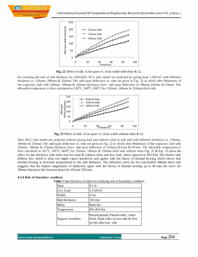
For studying the role of slab thickness by ABAQUS, RCC slab model are analyzed by giving load 1.5kN/m2 with different
thickness i.e. 150mm, 180mm & 250mm. The mid-span deflection vs. time are given in Fig. 22 in which after 90minutes of
fire exposure, slab with 150mm, 180mm & 250mm thickness have mid-span deflection of 196mm,163mm &119mm. The
allowable temperature is then calculated as 5200C, 560
0C, 660
0C for 150mm, 180mm & 250mm thick slab.
0
50
100
150
200
250
0 20 40 60 80 100
Mid
-sp
an
de
fle
ctio
n(m
m)
Time(min)
250mm Slab150mm Slab180mm slab
Fig. 23 Effect of slab, 4.5m span c/c, 4.5m width without rebar & LL
Here, RCC slab model are analyzed without giving load and without rebar in slab and with different thickness i.e. 150mm,
180mm & 250mm. The mid-span deflection vs. time are given in Fig. 22 in which after 90minutes of fire exposure, slab with
150mm, 180mm & 250mm thickness have mid-span deflection of 234mm,201mm &147mm. The allowable temperature is
then calculated as 5410C, 585
0C, 664
0C for 150mm, 180mm & 250mm thick slab without rebar.Fig. 22 & Fig. 23 show the
effect of slab thickness with rebar and live load & without rebar and live load, when exposed to ISO 834. The thicker slab
deflects less which is what one might expect intuitively and agrees with the theory of thermal bowing which shows that
thermal bowing is inversely proportional to the slab thickness. The defection curve for th e non-loaded 180mm thick slab
suggests that the relative magnitudes of deflection agree with the theory of thermal bowing up to 90 min the curve for
180mm thickness lies between those for 150 and 250 mm.
4.3.4 Role of boundary condition
Table 5 Specification of slabs for studying role of boundary condition
Span 4.5 m
Live Load 1.5 kN/m2
Width 4.5m
Slab thickness 150 mm
Rebar 8mm dia
Temperature ISO-834 fire
Support condition
Pinned-pinned, Pinned-roller, fixed-
fixed, fixed ro ller on two side & Free
on the other two side
International Journal Of Computational Engineering Research (ijceronline.com) Vol. 3 Issue. 1
||Issn 2250-3005(online)|| ||January || 2013 Page 205
Fig. 24 Effect of slab on different boundary condition, 4.5m span c/c, 4.5m width with LL
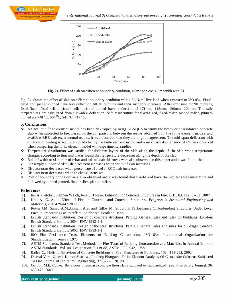
Fig. 24 shows the effect of slab on different boundary condition with 1.5 kN/m2 live load when exposed to ISO 834. Fixed-
fixed and pinned-pinned have less deflection till 20 minutes and then suddenly increases. After exposure for 90 minutes,
fixed-fixed, fixed-ro ller, p inned-roller, p inned-pinned have deflection of 171mm, 115mm, 196mm, 204mm. The safe
temperatures are calculated from allowable deflection. Safe temperature for fixed-fixed, fixed-roller, pinned-ro ller, pinned-
pinned are 748 0C, 604
0C, 541
0C, 717
0C.
5. Conclusions An accurate finite element model has been developed by using ABAQUS to study the behavior of reinforced concrete
slab when subjected to fire. Based on the comparisons between the results obtained from the finite element models and
available BRE slab experimental results, it was observed that they are in good agreement. The mid -span deflection with
duration of heating is accurately predicted by the finite element model and a maximum d iscrepancy of 6% was observed
when comparing the fin ite element model with experimental studies.
Temperature distribution was studied for different layers of the slab along the depth of t he slab when temperature
changes according to time and it was found that temperature decreases along the depth of the slab
Role of width of slab, role of rebar and role of slab thickness were also observed in this paper and it was found that
For simply supported slab , displacement increases when width of slab increases
Displacement decreases when percentage of steel in RCC slab increases
Displacement decreases when thickness increases
Role of boundary condition were also observed and it was found that fixed-fixed have the highest safe temperature and
followed by pinned-pinned, fixed-ro ller, pinned-roller.
References [1]. Ian A. Fletcher, Stephen Welch, José L. Torero. Behaviour of Concrete Structures in Fire. BIBLID, 112: 37-52, 2007
[2]. Khoury, G. A. . Effect of Fire on Concrete and Concrete Structures. Progress in Structural Engineering and
Materials, 2, 4: 429-447.2000
[3]. Rotter J.M, Sanad A.M.,Us mani A.S. and Gillie .M. Structural Performance Of Redundant Structures Under Local
Fires In Proceedings of Interflam. Edinburgh, Scotland, 1999.
[4]. British Standards Institution. Design of concrete structures, Part 1.1 General rules and rules for buildings. London:
British Standard Institute 2004. ENV 1992-1-1.
[5]. British Standards Institution. Design of the steel structures , Part 1.1 General ru les and rules for buildings. London:
British Standard Institute 2002. ENV 1993-1-1.
[6]. ISO Fire Resistance Tests. Elements of Building Construction, ISO 834, International Organization for
Standardization. Geneva, 1975
[7]. ASTM Standards. Standard Test Methods for Fire Tests of Building Construction and Materials, in Annual Book of
ASTM Standards. Vol. 04, Designation: E 119-88, ASTM, 922–942, 1988
[8]. Bailey C.. Holistic Behaviour of Concrete Build ings in Fire. Structures & Buildings, 152 : 199-212, 2002
[9]. Dhaval Vora, Umesh Kumar Sharma , Pradeep Bhargava. Fin ite Element Analysis Of Composite Columns Subjected
To Fire. Journal of Structural Engineering, 37: 322 – 328, 2010.
[10]. Gordon M.E. Cooke. Behaviour of precast concrete floor slabs exposed to standardized fires. Fire Safety Journal, 36:
459-475. 2001.
International Journal Of Computational Engineering Research (ijceronline.com) Vol. 3 Issue. 1
||Issn 2250-3005(online)|| ||January || 2013 Page 206
[11]. Kang S.W. and Hong, S.G.. Material Model and Thermal Response Analysis of Concrete at Elevated Temperatures.
Journal of the Korea Concrete Institute, 13: 268–276, 2001.
[12]. Kang, Suk Won, Hong, Sung-Gul . Behavior of Concrete Members at Elevated Temperatures Considering Inelastic
Deformat ion. Fire Technology, 39:9–22, 2003
[13]. Kuldeep Prasad, Howard R. Baum . Coupled Thermal-Elastic Response of Structures to Fires Building and Fire
Research Laboratory. National Institute of Standards and Technology Gaithersburg, MD 20899, 2006.
[14]. Li L, Purkiss J. Stress-Strain Constitutive Equations of Concrete Material at Elevated Temperatures. Fire Safety
Journal, 40: 669-686, 2005.
[15]. Mirza O, B. Uy . Behaviour of headed stud shear connectors for composite steel–concrete beams at elevated
temperatures. Journal of Constructional Steel Research, 65: 662–674, 2009.
[16]. Schneider U. Concrete at High Temperatures – A General Review. Fire Safety Journal, 13: 55-68, 1988.
[17]. Sebastjan Bratina, Bojan Cas, Miran Saje, Igor Planinc. Numerical modelling of behaviour of reinforced concrete
columns in fire and comparison with Euro code 2. International Journal of Solids and Structures , 42: 5715–5733,
2005.
[18]. Terro, M. J. . Numerical Mod el ling of the Behaviour of Concrete Structures. ACI Struct Journal, 95: 183-93, 1998.
[19]. Usmani, A. S., Rotter, J. M., Lamont, S., Sanad, A. M., Gillie M. Fundamental Princip les of Structural Behaviour
under Thermal Effects. Fire Safety Journal, 36: 721-744, 2001.