Embed Size (px)
Citation preview
Recent activities on the compatibility of the ferritic steel wallwith the plasma in the JFT-2M tokamak
K. Tsuzuki *, M. Sato, H. Kawashima, N. Isei, H. Kimura, H. Ogawa,K. Miyachi, M. Yamamoto, T. Shibata
Experimental Plasma Physics Laboratory, Japan Atomic Energy Research Institute, Shirakata Shirane, Tokai-mura,
Ibaraki-ken 319-1195, Japan
Abstract
The compatibility of the low activation ferritic steel with a fusion plasma has been investigated in the JFT-2M
tokamak. The program consists of three stages. In the first stage, the reduction of fast ion losses was well demonstrated
by ferritic steel plates (FPs) outside the vacuum vessel (VV). In the second stage, 20% of the inner surface of the VV was
covered by the FPs. The plasma control, stability, and impurity release were preliminary investigated. No deteriorative
effect on the plasma was observed at least in the following conditions: partial covering of 20% and the normalized beta
value less than 2.8. First boronization was applied to JFT-2M leading to a remarkable decrease of the oxygen impurity.
After the boronization, plasmas with the highest normalized beta in JFT-2M were obtained. Thus encouraging results
were gained for this stage. In the third stage, the VV was fully covered by FPs, where the ripple reduction and the
plasma stability will be investigated as a full scale testing.
� 2002 Elsevier Science B.V. All rights reserved.
1. Introduction
The low activation ferritic steel is one of the candi-
date materials for a demo-reactor [1]. It shows good
properties for thermal and neutron irradiation com-
pared to the conventional stainless steel [2]. However, it
is ferromagnetic material, and thus, one must fear that
the plasma confinement and stability might degrade due
to the field error. In addition, impurity release might be
problematic because the ferritic steel easily rusts in air
and retained oxygen is several times larger than that of
the stainless steel [3,4]. Thus, it is important to investi-
gate the compatibility with plasmas, before applying it
to a reactor. Another motivation for the use of ferritic
steel is a ripple reduction. The calculation in ITER
showed that the ripple losses of fast ions would be a
severe problem in steady state operation [5]. It is pro-
posed that the proper arrangement of the ferritic steel
allows a reduction of the toroidal field ripple [6–9]. The
use of the ferromagnetic material is planed in ITER [10].
So, the ferritic steel is rather effective to improve plasma
if the compatibility with the plasma is demonstrated.
In the small tokamak, HT-2, the ferritic steel, F82H,
was installed inside the vacuum vessel (VV) [11,12]. The
plasma control and impurity desorption were primary
investigated. The compatibility of the ferritic steel was
well demonstrated for ohmic heating plasma. For the
next step, the effect on the plasma confinement and
stability should be investigated in a higher performance
plasma, i.e. H mode condition. In the medium size
tokamak JFT-2M (R ¼ 1:31 m, a ¼ 0:31 m, BT 6 2:2 T),
testing of ferritic steel as wall material, advanced mate-
rial tokamak experiment (AMTEX), is in progress
[13–20]. The test consists of three stages, namely (1) in-
stallation of the ferritic steel plates (FPs) outside the VV,
(2) partial covering of the VV wall with the FPs, and (3)
full covering of the VV. Now, we finished the experiment
of the second stage and are preparing the third stage.
Journal of Nuclear Materials 307–311 (2002) 1386–1390
www.elsevier.com/locate/jnucmat
* Corresponding author. Tel.: +81-29 282 5559; fax: +81-29
282 5614.
E-mail address: [email protected] (K. Tsu-
zuki).
0022-3115/02/$ - see front matter � 2002 Elsevier Science B.V. All rights reserved.
PII: S0022 -3115 (02 )01126 -1
2. Ripple reduction experiment
The FPs, F82H, were inserted between the VV and all
(16) toroidal field coils (TFCs), aiming at reducing to-
roidal field ripple [13–19]. The main purpose of this
stage is to demonstrate experimentally the reduction of
fast ion losses. The form of the field ripple differs
strongly from that produced by TFCs only because the
magnetic field from the ferritic steel is not sinusoidal but
includes higher harmonics [13,14]. The dependence on
ripple profile was investigated by changing the FP thick-
ness and the toroidal field strength [15,16]. The results
show that the key parameter for the reduction of the
ripple loss is a fundamental component around the
shoulder part [15,16].
The un-periodicity of the FP installation due to the
interference with existing ports makes the toroidal dis-
tribution more complex. The results show that the ripple
loss is not sensitive to the local ripple but to the averaged
ripple [17].
No deteriorative effect on plasma confinement and
stability was observed. The improved confinement mode
is obtained using the conventional procedure in single-
null divertor configuration [15,18,19]. Thus, the ripple
reduction using ferromagnetic material is well demon-
strated.
3. Installation of the ferritic steel inside the vacuum vessel
The FPs were installed inside the VV to simulate the
blanket wall of the reactor. The position of the ferritic
steel is much closer to the plasma, and thus, the effect on
the plasma stability and control is different from the first
stage. In order to investigate the effects preliminarily,
two sets of toroidally uniform FP’s belts (F82H) of
7 mm thickness were installed, by which 20% of the VV
surface was covered [16,20]. The position of the FPs and
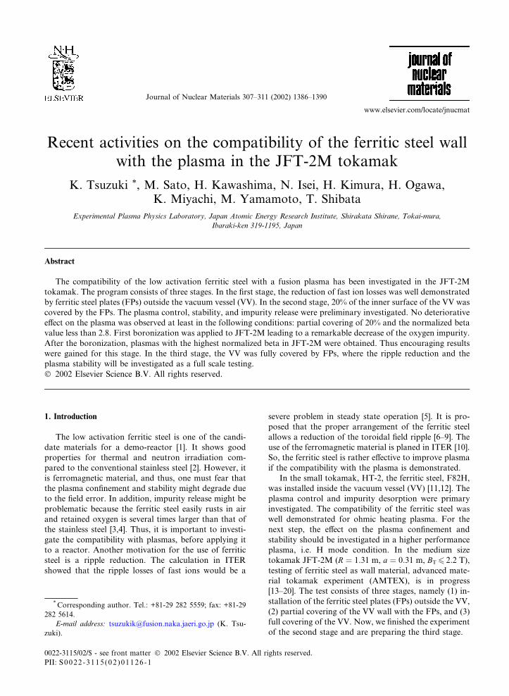
their effect are schematically illustrated in Fig. 1. The
ferritic plates (FP) are magnetized in poloidal direction
and generate a magnetic field as shown in the figure. The
plasma control is affected because the field weakens the
poloidal field and affects locally the magnetic probes,
which is located on VV for plasma control. In addition,
an enhancement of the MHD instability might be in-
duced, since the behavior of the wall is different from a
normal resistive wall, which is installed to stabilize the
MHD instability [21]. However, if the frequency of the
fluctuation is sufficiently high, an eddy current is
strongly induced, reducing the effect of the ferromag-
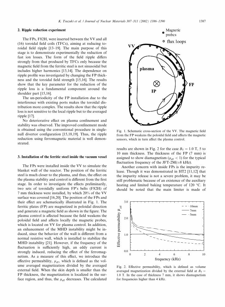
netism. As a measure of this effect, we introduce the
effective permeability, lrff , which is defined as the vol-
ume averaged magnetization divided by the averaged
external field. When the skin depth is smaller than the
FP thickness, the magnetization is localized in the sur-
face region, and thus, the leff decreases. The calculated
results are shown in Fig. 2 for the case BT ¼ 1:0 T, 5 to
10 mm thickness. The thickness of the FP (7 mm) is
assigned to show diamagnetism (leff < 1) for the typical
fluctuation frequency of the JFT-2M(’8 kHz).
Another concern with inside FPs is the impurity re-
lease. Though it was demonstrated in HT2 [11,12] that
the impurity release is not a severe problem, it may be
still problematic because of an existence of the auxiliary
heating and limited baking temperature of 120 �C. It
should be noted that the main limiter is made of
Fig. 1. Schematic cross-section of the VV. The magnetic field
from the FP weakens the poloidal field and affects the magnetic
sensors, which in turn affect the plasma control.
Fig. 2. Effective permeability, which is defined as volume
averaged magnetization divided by the external field at BT ¼1:0 T. In the case of thickness 7 mm, it shows diamagnetism
for frequencies higher than 4 kHz.
K. Tsuzuki et al. / Journal of Nuclear Materials 307–311 (2002) 1386–1390 1387
graphite, and the position of the FPs is 20 mm behind
the limiter. A boronization system was installed to re-
duce impurity desorption, and to achieve higher per-
formance plasmas with reduced impurities. Checking the
effect of the boronization was also important in the
second stage.
Before the installation, the FPs were baked at 350 �Cfor 20 h, according to Ref. [3]. The base pressure of
’10�6 Pa (same as previous condition) was obtained
after pumping, 120 �C baking and Taylor discharge
cleaning. The plasma was generated using the same
procedure as before. Small outward shift (’5% of the
minor radius) in the plasma position compared to the
equilibrium calculation was observed, which agrees with
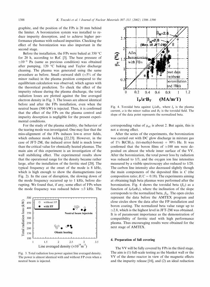
the theoretical prediction. To check the effect of the
impurity release during the plasma discharge, the total
radiation losses are plotted against the line averaged
electron density in Fig. 3. The losses are almost identical
before and after the FPs installation, even when the
neutral beam (500 kW) is injected. Thus, it is confirmed
that the effect of the FPs on the plasma control and
impurity desorption is negligible for the present experi-
mental conditions.
For the study of the plasma stability, the behavior of
the tearing mode was investigated. One may fear that the
miss-alignment of the FPs induces low-n error fields,
which enhance mode locking [22,23]. However, in the
case of JFT-2M, the induced error field is much lower
than the critical value for ohmically heated plasmas. The
main aim of this experiment is an investigation of the
wall stabilizing effect. The experimental results show
that the operational range for the density became rather
large, after the installation of the ferritic steel [20]. The
typical frequency at the onset of the mode is 8 kHz,
which is high enough to show the diamagnetisms (see
Fig. 2). In the case of disruption, the slowing down of
the mode frequency occurred up to 1 kHz, before dis-
rupting. We found that, if any, some effect of FPs when
the mode frequency was reduced below ’3 kHz. The
corresponding value of leff is about 2. But again, this is
not a strong effect.
After the series of the experiments, the boronization
was carried out with DC glow discharge in mixture gas
of 1% B(CH3)3 (tri-methyl-boron) þ 99% He. It was
confirmed that the boron films of ’100 nm were de-
posited on almost the whole inner surface of the VV.
After the boronization, the total power loss by radiation
was reduced to 1/3, and the oxygen ion line intensities
measured by a visible spectroscopy also reduced to 1/20.
The carbon line intensity also decreased slightly though
the main components of the deposited film is C (the
composition ratio; B=C ¼ 0:18). The experiments aiming
at obtaining high beta plasmas were performed after the
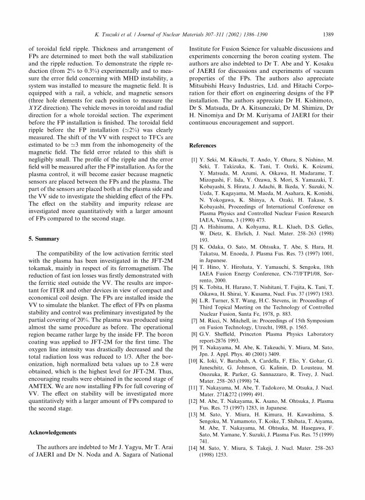
boronization. Fig. 4 shows the toroidal beta (bT) as a
function of IP/(aBT), where the inclination of the slope
corresponds to the normalized beta, bN. The open circles
represent the data before the AMTEX program and
close circles show the data after the FP installation and
boron coating. The normalized beta value range up to
’2.8, which is the highest level in JFT-2M was obtained.
It is of paramount importance as the demonstration of
compatibility of ferritic steel with high performance
plasma. Thus encouraging results were obtained for the
next stage of AMTEX.
4. Preparation of full covering
The VV will be fully covered by FPs in the third stage.
The aim is (1) full-scale testing as the blanket wall or the
VV of the demo reactor in view of the magnetic effects
and the impurity release [16], and (2) an ideal reduction
Fig. 3. Total radiation loss power against line averaged density.
The power is almost identical with and without FP even when a
neutral beam is injected.
Fig. 4. Toroidal beta against Ip/aBT, where Ip is the plasma
current, a is the minor radius and BT is the toroidal field. The
slope of the data point represents the normalized beta.
1388 K. Tsuzuki et al. / Journal of Nuclear Materials 307–311 (2002) 1386–1390
of toroidal field ripple. Thickness and arrangement of
FPs are determined to meet both the wall stabilization
and the ripple reduction. To demonstrate the ripple re-
duction (from 2% to 0.3%) experimentally and to mea-
sure the error field concerning with MHD instability, a
system was installed to measure the magnetic field. It is
equipped with a rail, a vehicle, and magnetic sensors
(three hole elements for each position to measure the
XYZ direction). The vehicle moves in toroidal and radial
direction for a whole toroidal section. The experiment
before the FP installation is finished. The toroidal field
ripple before the FP installation (’2%) was clearly
measured. The shift of the VV with respect to TFCs are
estimated to be ’3 mm from the inhomogeneity of the
magnetic field. The field error related to this shift is
negligibly small. The profile of the ripple and the error
field will be measured after the FP installation. As for the
plasma control, it will become easier because magnetic
sensors are placed between the FPs and the plasma. The
part of the sensors are placed both at the plasma side and
the VV side to investigate the shielding effect of the FPs.
The effect on the stability and impurity release are
investigated more quantitatively with a larger amount
of FPs compared to the second stage.
5. Summary
The compatibility of the low activation ferritic steel
with the plasma has been investigated in the JFT-2M
tokamak, mainly in respect of its ferromagnetism. The
reduction of fast ion losses was firstly demonstrated with
the ferritic steel outside the VV. The results are impor-
tant for ITER and other devices in view of compact and
economical coil design. The FPs are installed inside the
VV to simulate the blanket. The effect of FPs on plasma
stability and control was preliminary investigated by the
partial covering of 20%. The plasma was produced using
almost the same procedure as before. The operational
region became rather large by the inside FP. The boron
coating was applied to JFT-2M for the first time. The
oxygen line intensity was drastically decreased and the
total radiation loss was reduced to 1/3. After the bor-
onization, high normalized beta values up to 2.8 were
obtained, which is the highest level for JFT-2M. Thus,
encouraging results were obtained in the second stage of
AMTEX. We are now installing FPs for full covering of
VV. The effect on stability will be investigated more
quantitatively with a larger amount of FPs compared to
the second stage.
Acknowledgements
The authors are indebted to Mr J. Yagyu, Mr T. Arai
of JAERI and Dr N. Noda and A. Sagara of National
Institute for Fusion Science for valuable discussions and
experiments concerning the boron coating system. The
authors are also indebted to Dr T. Abe and Y. Kosaku
of JAERI for discussions and experiments of vacuum
properties of the FPs. The authors also appreciate
Mitsubishi Heavy Industries, Ltd. and Hitachi Corpo-
ration for their effort on engineering designs of the FP
installation. The authors appreciate Dr H. Kishimoto,
Dr S. Matsuda, Dr A. Kitsunezaki, Dr M. Shimizu, Dr
H. Ninomiya and Dr M. Kuriyama of JAERI for their
continuous encouragement and support.
References
[1] Y. Seki, M. Kikuchi, T. Ando, Y. Ohara, S. Nishino, M.
Seki, T. Takizuka, K. Tani, T. Ozeki, K. Koizumi,
Y. Matsuda, M. Azumi, A. Oikawa, H. Madarame, T.
Mizogushi, F. Iida, Y. Ozawa, S. Mori, S. Yamazaki, T.
Kobayashi, S. Hirata, J. Adachi, B. Ikeda, Y. Suzuki, N.
Ueda, T. Kagayama, M. Maeda, M. Asahara, K. Konishi,
N. Yokogawa, K. Shinya, A. Ozaki, H. Takase, S.
Kobayashi, Proceedings of International Conference on
Plasma Physics and Controlled Nuclear Fusion Research
IAEA, Vienna, 3 (1990) 473.
[2] A. Hishinuma, A. Kohyama, R.L. Klueh, D.S. Gelles,
W. Dietz, K. Ehrlich, J. Nucl. Mater. 258–263 (1998)
193.
[3] K. Odaka, O. Sato, M. Ohtsuka, T. Abe, S. Hara, H.
Takatsu, M. Enoeda, J. Plasma Fus. Res. 73 (1997) 1001,
in Japanese.
[4] T. Hino, Y. Hirohata, Y. Yamauchi, S. Sengoku, 18th
IAEA Fusion Energy Conference, CN-77/FTP1/08, Sor-
rento, 2000.
[5] K. Tobita, H. Harano, T. Nishitani, T. Fujita, K. Tani, T.
Oikawa, H. Shirai, Y. Kusama, Nucl. Fus. 37 (1997) 1583.
[6] L.R. Turner, S.T. Wang, H.C. Stevens, in: Proceedings of
Third Topical Meeting on the Technology of Controlled
Nuclear Fusion, Santa Fe, 1978, p. 883.
[7] M. Ricci, N. Mitchell, in: Proceedings of 15th Symposium
on Fusion Technology, Utrecht, 1988, p. 1565.
[8] G.V. Sheffield, Princeton Plasma Physics Laboratory
report-2876 1993.
[9] T. Nakayama, M. Abe, K. Takeuchi, Y. Miura, M. Sato,
Jpn. J. Appl. Phys. 40 (2001) 3409.
[10] K. Ioki, V. Barabash, A. Cardella, F. Elio, Y. Gohar, G.
Janeschitz, G. Johnson, G. Kalinin, D. Lousteau, M.
Onozuka, R. Parker, G. Sannazzaro, R. Tivey, J. Nucl.
Mater. 258–263 (1998) 74.
[11] T. Nakayama, M. Abe, T. Tadokoro, M. Otsuka, J. Nucl.
Mater. 271&272 (1999) 491.
[12] M. Abe, T. Nakayama, K. Asano, M. Ohtsuka, J. Plasma
Fus. Res. 73 (1997) 1283, in Japanese.
[13] M. Sato, Y. Miura, H. Kimura, H. Kawashima, S.
Sengoku, M. Yamamoto, T. Koike, T. Shibata, T. Aiyama,
M. Abe, T. Nakayama, M. Ohtsuka, M. Hasegawa, F.
Sato, M. Yamane, Y. Suzuki, J. Plasma Fus. Res. 75 (1999)
741.
[14] M. Sato, Y. Miura, S. Takeji, J. Nucl. Mater. 258–263
(1998) 1253.
K. Tsuzuki et al. / Journal of Nuclear Materials 307–311 (2002) 1386–1390 1389
[15] H. Kawashima, M. Sato, K. Tsuzuki, Y. Miura, N. Isei, H.
Kimura, T. Nakayama, M. Abe, D.S. Darrow, JFT-2M
group, Nucl. Fus. 41 (2001) 257.
[16] H. Kimura, M. Sato, H. Kawashima, H. Kawashima, N.
Isei, K. Tsuzuki, H. Ogawa, T. Ogawa, Y. Miura, M.
Yamamoto, T. Shibata, T. Akiyama, K. Miyachi, JFT-2M
Group, Proceedings of 21st SOFT Fusion Engineering,
Design, Madrid, 2000, 56–57 (2001) 837.
[17] H. Kawashima, K. Tsuzuki, N. Isei, M. Sato, K. Shino-
hara, H. Kimura, Proceedings of 28th European Confer-
ence on Controlled Fusion and Plasma Physics, Madeira:
EPS, 2001, p. 4.001.
[18] K. Tsuzuki, M. Sato, H. Kawashima, Y. Miura, H.
Kawashima, T. Abe, K. Uehara, T. Ogawa, T. Akiyama,
T. Shibata, M. Yamamoto, JFT-2M Group, J. Nucl.
Mater. 283–287 (2000) 681.
[19] M. Sato, H. Kawashima, Y. Miura, K. Tsuzuki, H.
Kimura, K. Uehara, T. Ogawa, N. Isei, T. Tani, T.
Akiyama, T. Shibata, M. Yamamoto, T. Koike, M. Abe,
T. Nakayama, Fus. Eng. Des. 51–52 (2000) 1071.
[20] N. Isei, M. Sato, K. Tsuzuki, H. Kawashima, Y. Miura, H.
Kimura, JFT-2M Group, Fus. Technol. 39 (2001) 1101.
[21] ITER Physics Basis, Nucl. Fus. 39 (1999) 2260.
[22] S. Takeji, M. Mori, M. Kikuchi, H. Ninomiya, S.
Jitsukawa, T. Ito, M. Kuriyama, H. Kishimoto, Proceed-
ings of 16th IEEE/NPSS SOFE, Illinois, 1995, 1214.
[23] R.J. La Haye, R. Fitzpartrick, T.C. Hender, A.W. Morris,
J.T. Scoville, T.N. Todd, Phys. Fluids B 4 (1992) 2098.
1390 K. Tsuzuki et al. / Journal of Nuclear Materials 307–311 (2002) 1386–1390