Embed Size (px)
Citation preview
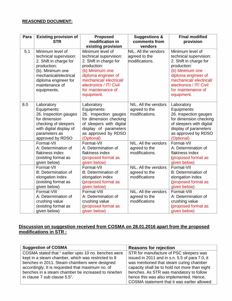
REASONED DOCUMENT:
Para Existing provision ofSTR
Proposedmodification in
existing provision
Suggestions &comments from
vendors
Final modifiedprovision
5.1 Minimum level oftechnical supervision:2. Shift in charge forproduction:(b). Minimum onemechanical/electricaldiploma engineer formaintenance ofequipments.
NIL. All the vendorsagreed to themodifications.
8.0 LaboratoryEquipments:26. Inspection gaugesfor dimensionchecking of sleeperswith digital display ofparameters asapproved by RDSO
LaboratoryEquipments:26. Inspection gaugesfor dimension checkingof sleepers with digitaldisplay of parametersas approved by RDSO(Optional)
NIL. All the vendorsagreed to themodifications.
LaboratoryEquipments:26. Inspection gaugesfor dimension checkingof sleepers with digitaldisplay of parametersas approved by RDSO(Optional)
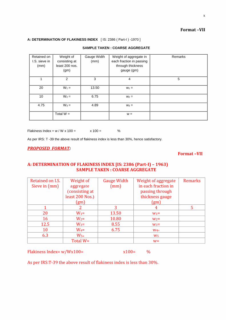
Format-VIIA: Determination offlakiness index(existing format asgiven below)
Format-VIIA: Determination offlakiness index(proposed format asgiven below)
NIL. All the vendorsagreed to themodifications.
Format-VIIA: Determination offlakiness index(proposed format asgiven below)
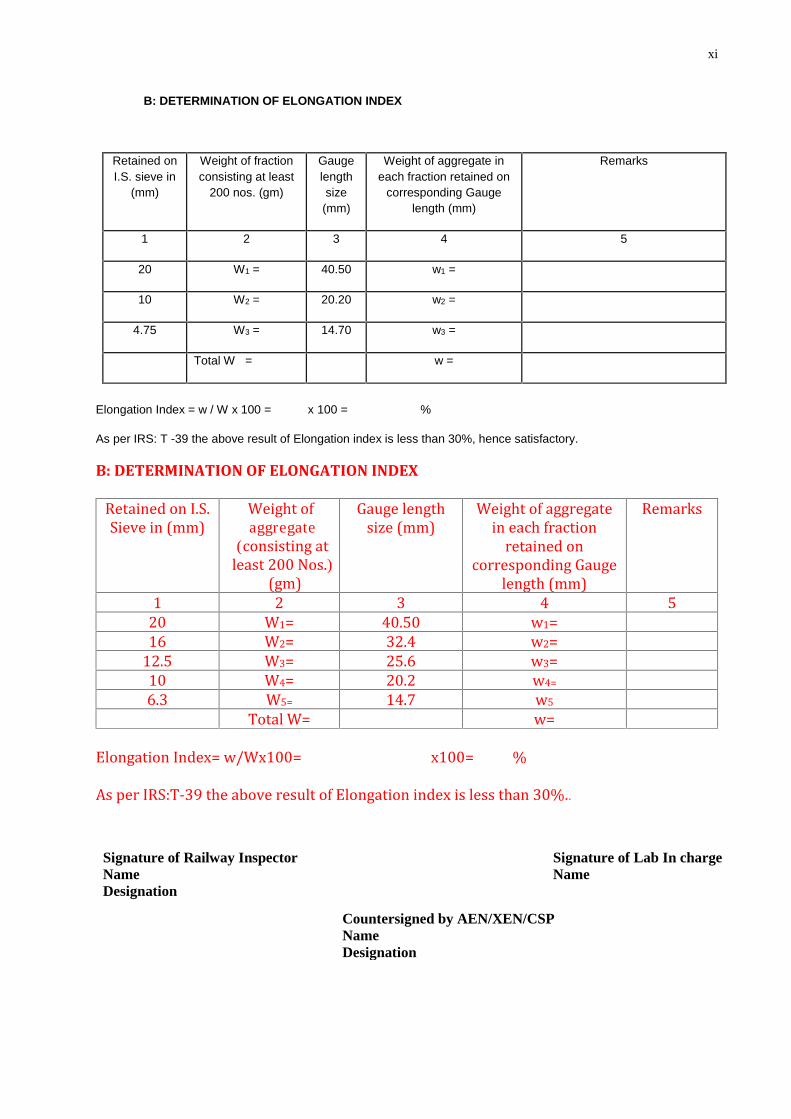
Format-VIIB: Determination ofelongation index(existing format asgiven below)
Format-VIIB: Determination ofelongation index(proposed format asgiven below)
NIL. All the vendorsagreed to themodifications
Format-VIIB: Determination ofelongation index(proposed format asgiven below)
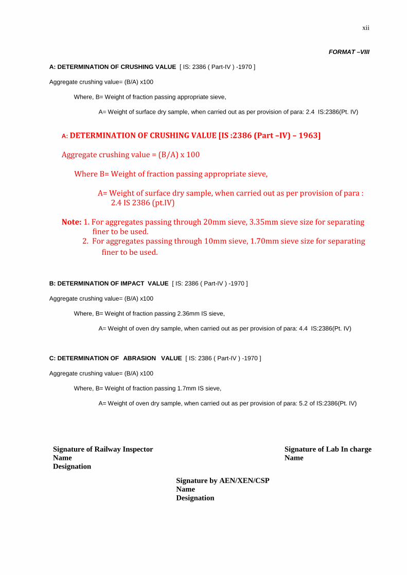
Format-VIIIA: Determination ofcrushing value(existing format asgiven below)
Format-VIIIA: Determination ofcrushing value(proposed format asgiven below)
NIL. All the vendorsagreed to themodifications
Format-VIIIA: Determination ofcrushing value(proposed format asgiven below)
Discussion on suggestion received from COSMA on 28.01.2016 apart from the proposedmodifications in STR :
Suggestion of COSMA Reasons for rejectionCOSMA stated that “ earlier upto 10 no. benches werekept in a steam chamber, which was restricted to 8benches in 2011. Steam chambers were designedaccordingly. It is requested that maximum no. ofbenches in a steam chamber be increased to nine/tenin clause 7 sub clause 5.5”.
STR for manufacture of PSC sleepers wasissued in 2011 and in s.n. 5.5 of para 7.0, itwas mentioned that steam curing chambercapacity shall be to hold not more than eightbenches. As STR was mandatory to followhence this was also implemented. Hence,COSMA statement that it was earlier allowed
Minimum level oftechnical supervision:2. Shift in charge forproduction:(b) Minimum onediploma engineer ofmechanical/ electrical/electronics / IT/ Civil for maintenance ofequipment.
Minimum level oftechnical supervision:2. Shift in charge forproduction:(b) Minimum onediploma engineer ofmechanical/ electrical/electronics / IT/ Civil for maintenance ofequipment.
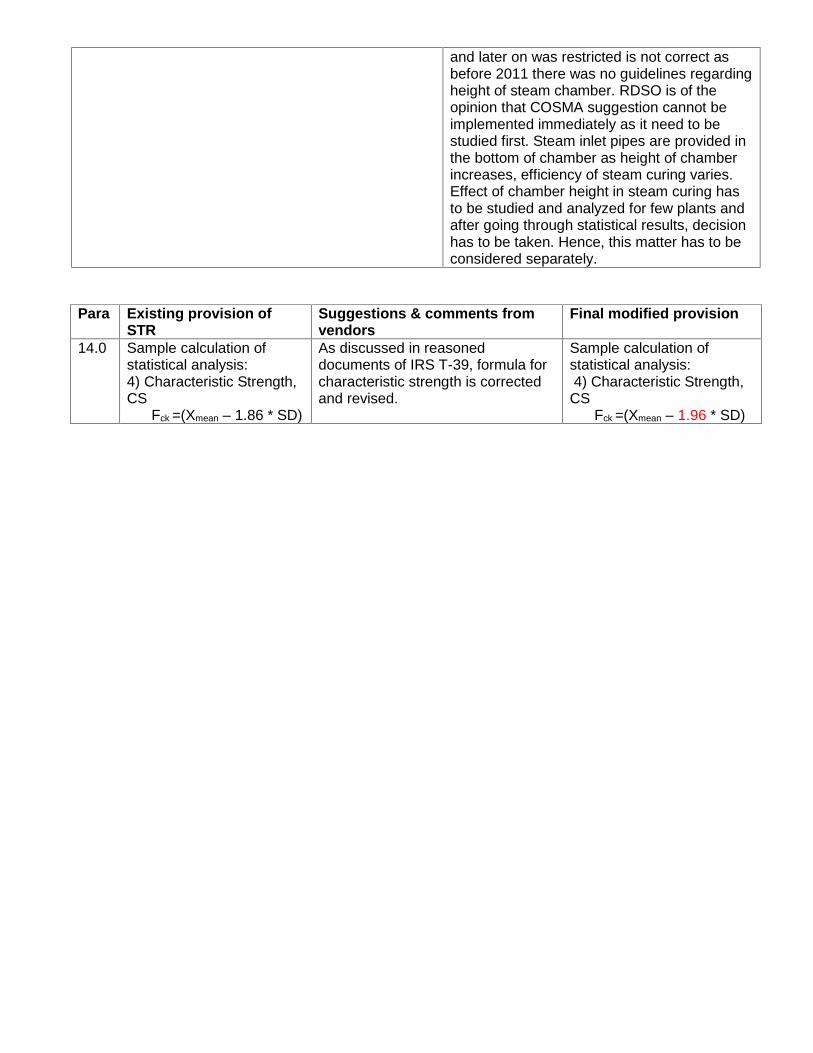
and later on was restricted is not correct asbefore 2011 there was no guidelines regardingheight of steam chamber. RDSO is of theopinion that COSMA suggestion cannot beimplemented immediately as it need to bestudied first. Steam inlet pipes are provided inthe bottom of chamber as height of chamberincreases, efficiency of steam curing varies.Effect of chamber height in steam curing hasto be studied and analyzed for few plants andafter going through statistical results, decisionhas to be taken. Hence, this matter has to beconsidered separately.
Para Existing provision ofSTR
Suggestions & comments fromvendors
Final modified provision
14.0 Sample calculation ofstatistical analysis:4) Characteristic Strength,CS
Fck =(Xmean – 1.86 * SD)
As discussed in reasoneddocuments of IRS T-39, formula forcharacteristic strength is correctedand revised.
Sample calculation ofstatistical analysis:4) Characteristic Strength,
CSFck =(Xmean – 1.96 * SD)
FORMAT -VII
A: DETERMINATION OF FLAKINESS INDEX [ IS: 2386 ( Part-I ) -1970 ]
SAMPLE TAKEN : COARSE AGGREGATE
Retained onI.S. sieve in
(mm)
Weight ofconsisting at
least 200 nos.(gm)
Gauge Width(mm)
Weight of aggregate ineach fraction in passing
through thicknessgauge (gm)
Remarks
1 2 3 4 5
20 W1 = 13.50 w1 =
10 W2 = 6.75 w2 =
4.75 W3 = 4.89 w3 =
Total W = w =
Flakiness Index = w / W x 100 = x 100 = %
As per IRS: T -39 the above result of flakiness index is less than 30%, hence satisfactory.
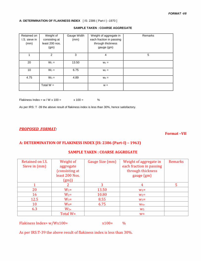
PROPOSED FORMAT:Format –VII
A: DETERMINATION OF FLAKINESS INDEX [IS: 2386 (Part-I) – 1963)
SAMPLE TAKEN : COARSE AGGREGATERetained on I.S.Sieve in (mm) Weight ofaggregate(consisting atleast 200 Nos.(gm))Gauge Size (mm) Weight of aggregate ineach fraction in passingthrough thicknessgauge (gm)
Remarks1 2 3 4 520 W1= 13.50 w1=16 W2= 10.80 w2=12.5 W3= 8.55 w3=10 W4= 6.75 w4=6.3 W5= w5Total W= w=Flakiness Index= w/Wx100= x100= %As per IRS:T-39 the above result of flakiness index is less than 30%.
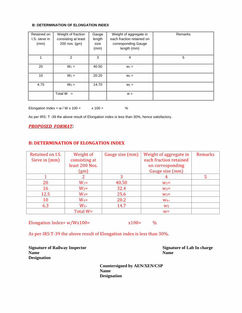
B: DETERMINATION OF ELONGATION INDEX
Retained onI.S. sieve in
(mm)
Weight of fractionconsisting at least
200 nos. (gm)
Gaugelengthsize(mm)
Weight of aggregate ineach fraction retained on
corresponding Gaugelength (mm)
Remarks
1 2 3 4 5
20 W1 = 40.50 w1 =
10 W2 = 20.20 w2 =
4.75 W3 = 14.70 w3 =
Total W = w =
Elongation Index = w / W x 100 = x 100 = %
As per IRS: T -39 the above result of Elongation index is less than 30%, hence satisfactory.
PROPOSED FORMAT:
B: DETERMINATION OF ELONGATION INDEXRetained on I.S.Sieve in (mm) Weight ofconsisting atleast 200 Nos.(gm)Gauge size (mm) Weight of aggregate ineach fraction retainedon correspondingGauge size (mm)
Remarks1 2 3 4 520 W1= 40.50 w1=16 W2= 32.4 w2=12.5 W3= 25.6 w3=10 W4= 20.2 w4=6.3 W5= 14.7 w5Total W= w=Elongation Index= w/Wx100= x100= %As per IRS:T-39 the above result of Elongation index is less than 30%.
Signature of Railway InspectorNameDesignation
Signature of Lab In chargeName
Countersigned by AEN/XEN/CSPNameDesignation
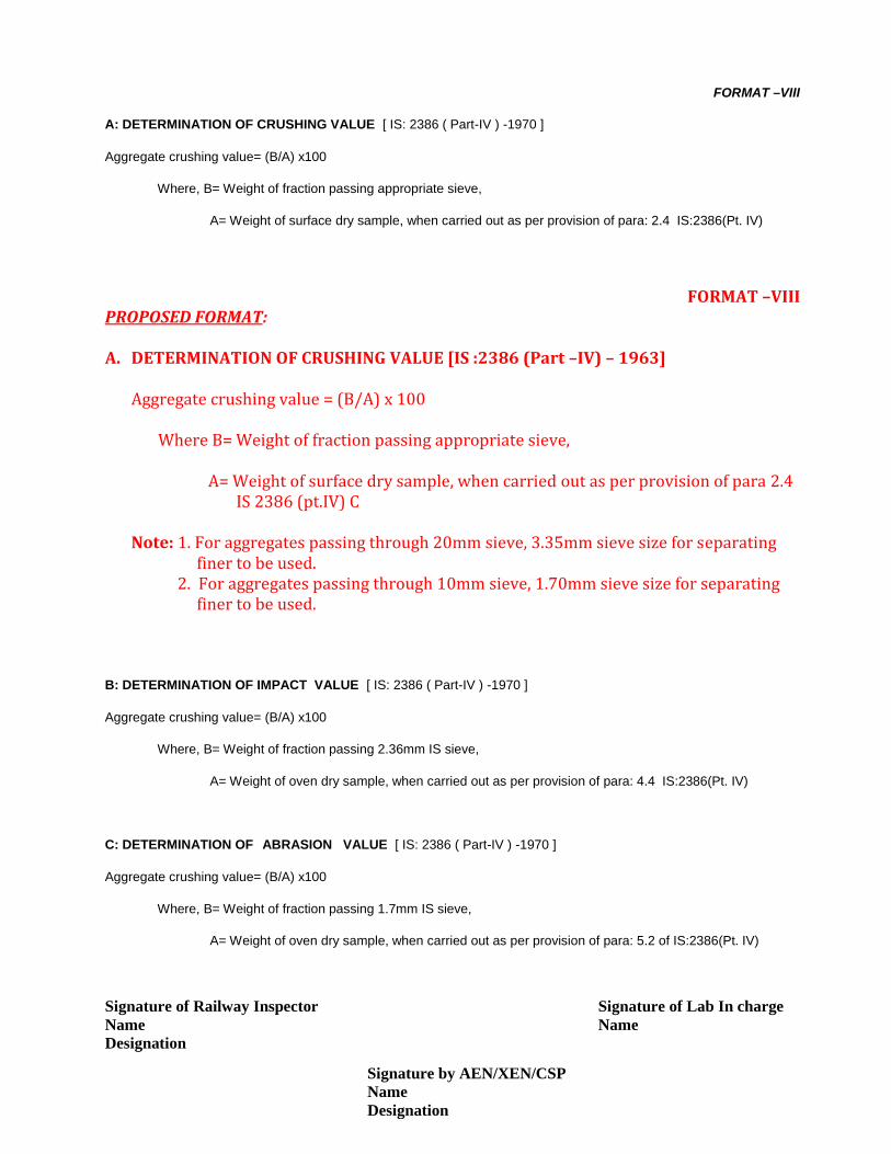
FORMAT –VIII
A: DETERMINATION OF CRUSHING VALUE [ IS: 2386 ( Part-IV ) -1970 ]
Aggregate crushing value= (B/A) x100
Where, B= Weight of fraction passing appropriate sieve,
A= Weight of surface dry sample, when carried out as per provision of para: 2.4 IS:2386(Pt. IV)
FORMAT –VIIIPROPOSED FORMAT:
Aggregate crushing value = (B/A) x 100Where B= Weight of fraction passing appropriate sieve,A= Weight of surface dry sample, when carried out as per provision of para 2.4IS 2386 (pt.IV) CNote: 1. For aggregates passing through 20mm sieve, 3.35mm sieve size for separatingfiner to be used.2. For aggregates passing through 10mm sieve, 1.70mm sieve size for separatingfiner to be used.
B: DETERMINATION OF IMPACT VALUE [ IS: 2386 ( Part-IV ) -1970 ]
Aggregate crushing value= (B/A) x100
Where, B= Weight of fraction passing 2.36mm IS sieve,
A= Weight of oven dry sample, when carried out as per provision of para: 4.4 IS:2386(Pt. IV)
C: DETERMINATION OF ABRASION VALUE [ IS: 2386 ( Part-IV ) -1970 ]
Aggregate crushing value= (B/A) x100
Where, B= Weight of fraction passing 1.7mm IS sieve,
A= Weight of oven dry sample, when carried out as per provision of para: 5.2 of IS:2386(Pt. IV)
Signature of Railway InspectorNameDesignation
Signature of Lab In chargeName
Signature by AEN/XEN/CSPNameDesignation
A. DETERMINATION OF CRUSHING VALUE [IS :2386 (Part –IV) – 1963]

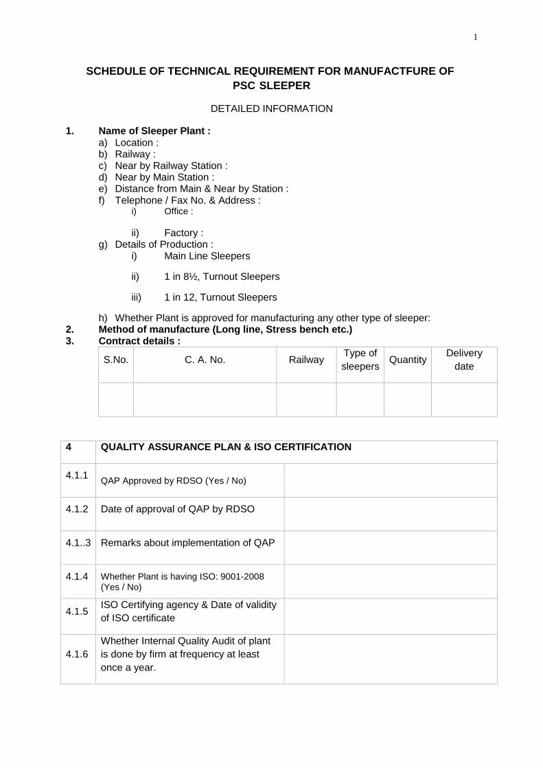
1
DETAILED INFORMATION
1. Name of Sleeper Plant :a) Location :b) Railway :c) Near by Railway Station :d) Near by Main Station :e) Distance from Main & Near by Station :f) Telephone / Fax No. & Address :
i) Office :
ii) Factory :g) Details of Production :
i) Main Line Sleepers
ii) 1 in 8½, Turnout Sleepers
iii) 1 in 12, Turnout Sleepers
h) Whether Plant is approved for manufacturing any other type of sleeper:2. Method of manufacture (Long line, Stress bench etc.)3. Contract details :
S.No. C. A. No. Railway Type ofsleepers Quantity Delivery
date
4 QUALITY ASSURANCE PLAN & ISO CERTIFICATION
4.1.1 QAP Approved by RDSO (Yes / No)
4.1.2 Date of approval of QAP by RDSO
4.1..3 Remarks about implementation of QAP
4.1.4 Whether Plant is having ISO: 9001-2008(Yes / No)
4.1.5 ISO Certifying agency & Date of validityof ISO certificate
4.1.6Whether Internal Quality Audit of plantis done by firm at frequency at leastonce a year.
SCHEDULE OF TECHNICAL REQUIREMENT FOR MANUFACTFURE OF PSC SLEEPER
2
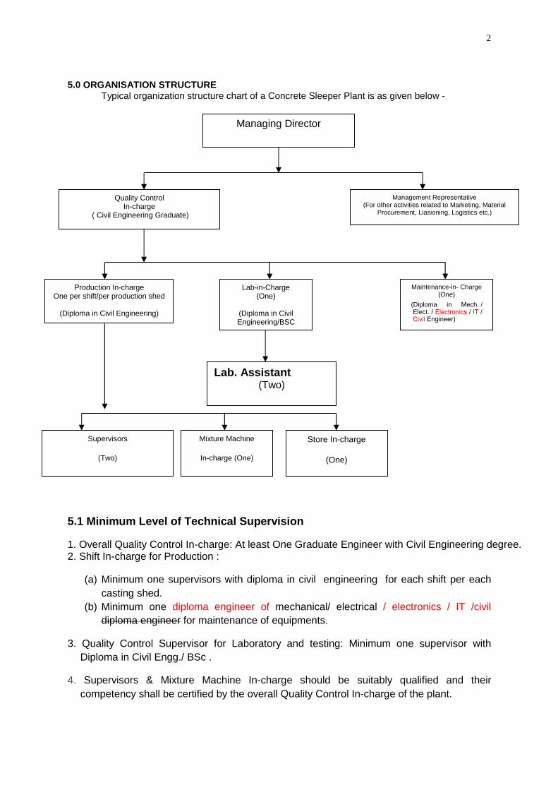
5.0 ORGANISATION STRUCTURETypical organization structure chart of a Concrete Sleeper Plant is as given below -
5.1 Minimum Level of Technical Supervision
1. Overall Quality Control In-charge: At least One Graduate Engineer with Civil Engineering degree.2. Shift In-charge for Production :
(a) Minimum one supervisors with diploma in civil engineering for each shift per eachcasting shed.
3. Quality Control Supervisor for Laboratory and testing: Minimum one supervisor withDiploma in Civil Engg./ BSc .
4. Supervisors & Mixture Machine In-charge should be suitably qualified and theircompetency shall be certified by the overall Quality Control In-charge of the plant.
Managing Director
Quality ControlIn-charge
( Civil Engineering Graduate)
Management Representative(For other activities related to Marketing, Material
Procurement, Liasioning, Logistics etc.)
Production In-chargeOne per shift/per production shed
(Diploma in Civil Engineering)
Rly. TransportManagement (One)
Lab-in-Charge(One)
(Diploma in CivilEngineering/BSC
Maintenance-in- Charge(One)
Lab. Assistant(Two)
Supervisors
(Two)
Mixture Machine
In-charge (One)
Store In-charge
(One)
Engineer)
a in Mech. / Elect. (Diplom
/ Electronics / IT / Civil
(b) Minimum one diploma engineer of mechanical/ electrical / electronics / IT /civildiploma engineer for maintenance of equipments.
3
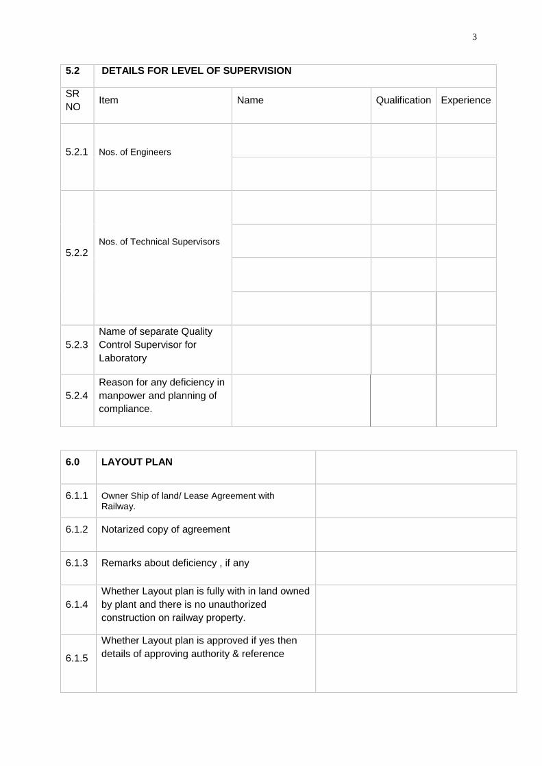
5.2 DETAILS FOR LEVEL OF SUPERVISION
SRNO Item Name Qualification Experience
5.2.1 Nos. of Engineers
5.2.2Nos. of Technical Supervisors
5.2.3Name of separate QualityControl Supervisor forLaboratory
5.2.4Reason for any deficiency inmanpower and planning ofcompliance.
6.0 LAYOUT PLAN
6.1.1 Owner Ship of land/ Lease Agreement withRailway.
6.1.2 Notarized copy of agreement
6.1.3 Remarks about deficiency , if any
6.1.4Whether Layout plan is fully with in land ownedby plant and there is no unauthorizedconstruction on railway property.
6.1.5
Whether Layout plan is approved if yes thendetails of approving authority & reference
4
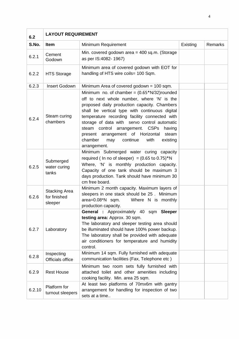
6.2 LAYOUT REQUIREMENT
S.No. Item Minimum Requirement Existing Remarks
6.2.1 CementGodown
Min. covered godown area = 400 sq.m. (Storageas per IS:4082- 1967)
6.2.2 HTS StorageMinimum area of covered godown with EOT forhandling of HTS wire coils= 100 Sqm.
6.2.3 Insert Godown Minimum Area of covered godown = 100 sqm.
6.2.4 Steam curingchambers
Minimum no. of chamber = (0.65*N/32)roundedoff to next whole number, where ‘N’ is theproposed daily production capacity. Chambersshall be vertical type with continuous digitaltemperature recording facility connected withstorage of data with servo control automaticsteam control arrangement. CSPs havingpresent arrangement of Horizontal steamchamber may continue with existingarrangement.
6.2.5Submergedwater curingtanks
Minimum Submerged water curing capacityrequired ( In no of sleeper) = (0.65 to 0.75)*NWhere, ‘N’ is monthly production capacity.Capacity of one tank should be maximum 3days production. Tank should have minimum 30cm free board.
6.2.6Stacking Areafor finishedsleeper
Minimum 2 month capacity. Maximum layers ofsleepers in one stack should be 25 . Minimumarea=0.08*N sqm. Where N is monthlyproduction capacity.
6.2.7 Laboratory
General : Approximately 40 sqm Sleepertesting area: Approx. 30 sqm.The laboratory and sleeper testing area shouldbe illuminated should have 100% power backup.The laboratory shall be provided with adequateair conditioners for temperature and humiditycontrol.
6.2.8 InspectingOfficials office
Minimum 14 sqm. Fully furnished with adequatecommunication facilities (Fax, Telephone etc )
6.2.9 Rest HouseMinimum two room sets fully furnished withattached toilet and other amenities includingcooking facility. Min. area 25 sqm.
6.2.10 Platform forturnout sleepers
At least two platforms of 70mx6m with gantryarrangement for handling for inspection of twosets at a time..
5
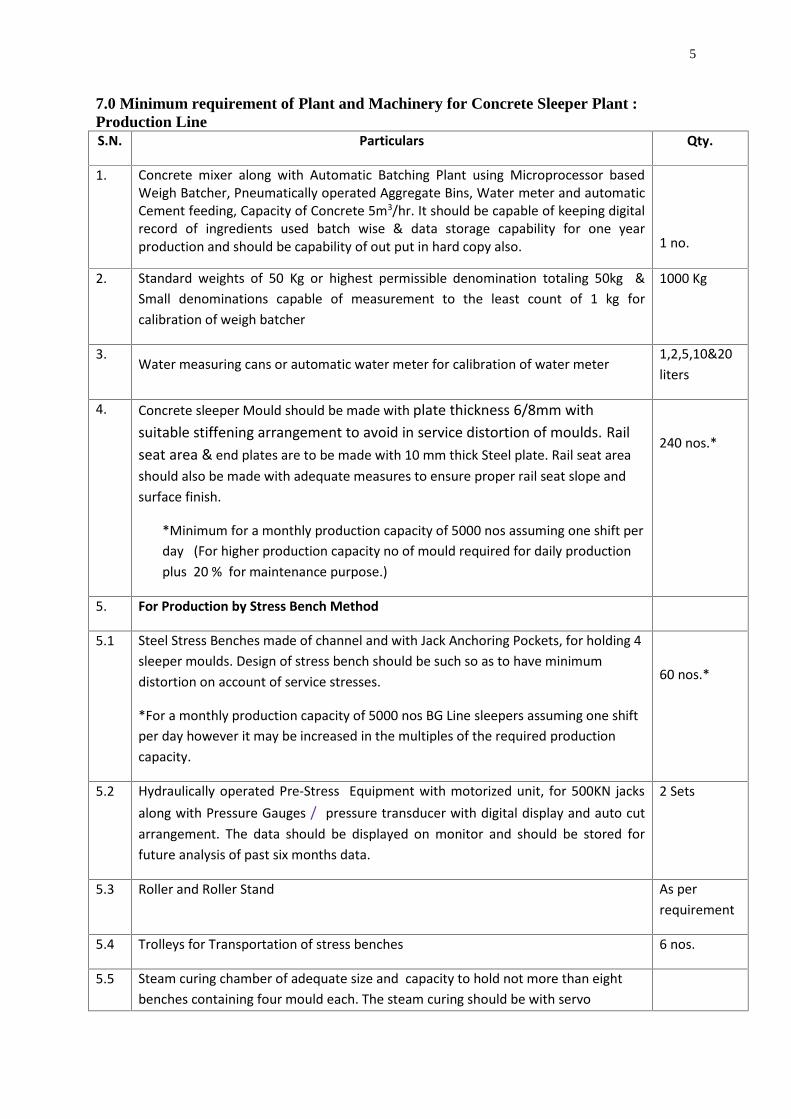
7.0 Minimum requirement of Plant and Machinery for Concrete Sleeper Plant :Production LineS.N. Particulars Qty.
1. Concrete mixer along with Automatic Batching Plant using Microprocessor basedWeigh Batcher, Pneumatically operated Aggregate Bins, Water meter and automaticCement feeding, Capacity of Concrete 5m3/hr. It should be capable of keeping digitalrecord of ingredients used batch wise & data storage capability for one yearproduction and should be capability of out put in hard copy also. 1 no.
2. Standard weights of 50 Kg or highest permissible denomination totaling 50kg &Small denominations capable of measurement to the least count of 1 kg forcalibration of weigh batcher
1000 Kg
3.Water measuring cans or automatic water meter for calibration of water meter
1,2,5,10&20liters
4. Concrete sleeper Mould should be made with plate thickness 6/8mm withsuitable stiffening arrangement to avoid in service distortion of moulds. Railseat area & end plates are to be made with 10 mm thick Steel plate. Rail seat areashould also be made with adequate measures to ensure proper rail seat slope andsurface finish.
*Minimum for a monthly production capacity of 5000 nos assuming one shift perday (For higher production capacity no of mould required for daily productionplus 20 % for maintenance purpose.)
240 nos.*
5. For Production by Stress Bench Method
5.1 Steel Stress Benches made of channel and with Jack Anchoring Pockets, for holding 4sleeper moulds. Design of stress bench should be such so as to have minimumdistortion on account of service stresses.
*For a monthly production capacity of 5000 nos BG Line sleepers assuming one shiftper day however it may be increased in the multiples of the required productioncapacity.
60 nos.*
5.2 Hydraulically operated Pre-Stress Equipment with motorized unit, for 500KN jacksalong with Pressure Gauges / pressure transducer with digital display and auto cutarrangement. The data should be displayed on monitor and should be stored forfuture analysis of past six months data.
2 Sets
5.3 Roller and Roller Stand As perrequirement
5.4 Trolleys for Transportation of stress benches 6 nos.
5.5 Steam curing chamber of adequate size and capacity to hold not more than eightbenches containing four mould each. The steam curing should be with servo
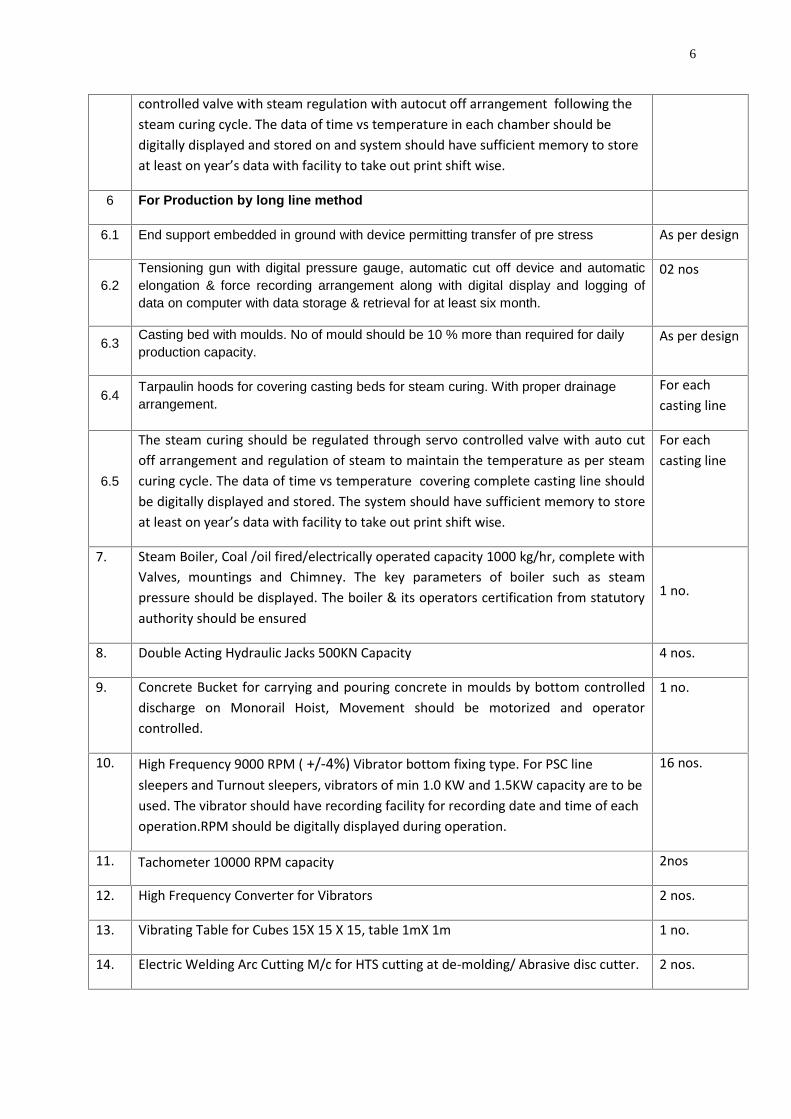
6
controlled valve with steam regulation with autocut off arrangement following thesteam curing cycle. The data of time vs temperature in each chamber should bedigitally displayed and stored on and system should have sufficient memory to storeat least on year’s data with facility to take out print shift wise.
6 For Production by long line method
6.1 End support embedded in ground with device permitting transfer of pre stress As per design
6.2Tensioning gun with digital pressure gauge, automatic cut off device and automaticelongation & force recording arrangement along with digital display and logging ofdata on computer with data storage & retrieval for at least six month.
02 nos
6.3 Casting bed with moulds. No of mould should be 10 % more than required for dailyproduction capacity.
As per design
6.4 Tarpaulin hoods for covering casting beds for steam curing. With proper drainagearrangement.
For eachcasting line
6.5
The steam curing should be regulated through servo controlled valve with auto cutoff arrangement and regulation of steam to maintain the temperature as per steamcuring cycle. The data of time vs temperature covering complete casting line shouldbe digitally displayed and stored. The system should have sufficient memory to storeat least on year’s data with facility to take out print shift wise.
For eachcasting line
7. Steam Boiler, Coal /oil fired/electrically operated capacity 1000 kg/hr, complete withValves, mountings and Chimney. The key parameters of boiler such as steampressure should be displayed. The boiler & its operators certification from statutoryauthority should be ensured
1 no.
8. Double Acting Hydraulic Jacks 500KN Capacity 4 nos.
9. Concrete Bucket for carrying and pouring concrete in moulds by bottom controlleddischarge on Monorail Hoist, Movement should be motorized and operatorcontrolled.
1 no.
10. High Frequency 9000 RPM ( +/-4%) Vibrator bottom fixing type. For PSC linesleepers and Turnout sleepers, vibrators of min 1.0 KW and 1.5KW capacity are to beused. The vibrator should have recording facility for recording date and time of eachoperation.RPM should be digitally displayed during operation.
16 nos.
11. Tachometer 10000 RPM capacity 2nos
12. High Frequency Converter for Vibrators 2 nos.
13. Vibrating Table for Cubes 15X 15 X 15, table 1mX 1m 1 no.
14. Electric Welding Arc Cutting M/c for HTS cutting at de-molding/ Abrasive disc cutter. 2 nos.
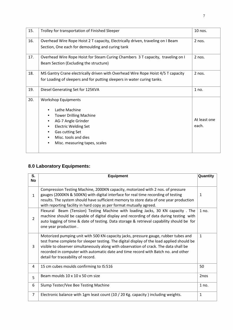
7
15. Trolley for transportation of Finished Sleeper 10 nos.
16. Overhead Wire Rope Hoist 2 T capacity, Electrically driven, traveling on I BeamSection, One each for demoulding and curing tank
2 nos.
17. Overhead Wire Rope Hoist for Steam Curing Chambers 3 T capacity, traveling on IBeam Section (Excluding the structure)
2 nos.
18. MS Gantry Crane electrically driven with Overhead Wire Rope Hoist 4/5 T capacityfor Loading of sleepers and for putting sleepers in water curing tanks.
2 nos.
19. Diesel Generating Set for 125KVA 1 no.
20. Workshop Equipments
Lathe Machine Tower Drilling Machine AG-7 Angle Grinder Electric Welding Set Gas cutting Set Misc. tools and dies Misc. measuring tapes, scales
At least oneeach.
8.0 Laboratory Equipments:
S.No
Equipment Quantity
1Compression Testing Machine, 2000KN capacity, motorized with 2 nos. of pressuregauges (2000KN & 500KN) with digital interface for real time recording of testingresults. The system should have sufficient memory to store data of one year productionwith reporting facility in hard copy as per format mutually agreed.
1
2
Flexural Beam (Tension) Testing Machine with loading Jacks, 30 KN capacity . Themachine should be capable of digital display and recording of data during testing withauto logging of time & date of testing. Data storage & retrieval capability should be forone year production .
1 no.
3
Motorized pumping unit with 500 KN capacity jacks, pressure gauge, rubber tubes andtest frame complete for sleeper testing. The digital display of the load applied should bevisible to observer simultaneously along with observation of crack. The data shall berecorded in computer with automatic date and time record with Batch no. and otherdetail for traceability of record.
1
4 15 cm cubes moulds confirming to IS:516 50
5 Beam moulds 10 x 10 x 50 cm size 2nos
6 Slump Tester/Vee Bee Testing Machine 1 no.
7 Electronic balance with 1gm least count (10 / 20 Kg. capacity ) including weights. 1
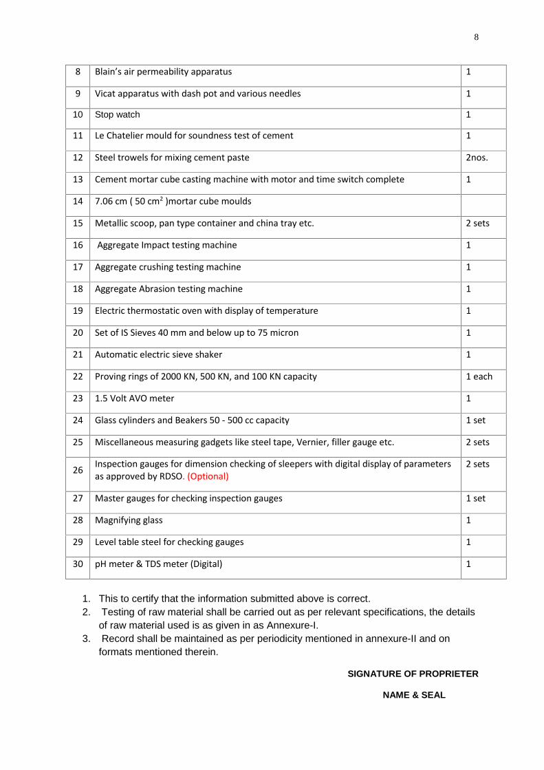
8
8 Blain’s air permeability apparatus 1
9 Vicat apparatus with dash pot and various needles 1
10 Stop watch 1
11 Le Chatelier mould for soundness test of cement 1
12 Steel trowels for mixing cement paste 2nos.
13 Cement mortar cube casting machine with motor and time switch complete 1
14 7.06 cm ( 50 cm2 )mortar cube moulds
15 Metallic scoop, pan type container and china tray etc. 2 sets
16 Aggregate Impact testing machine 1
17 Aggregate crushing testing machine 1
18 Aggregate Abrasion testing machine 1
19 Electric thermostatic oven with display of temperature 1
20 Set of IS Sieves 40 mm and below up to 75 micron 1
21 Automatic electric sieve shaker 1
22 Proving rings of 2000 KN, 500 KN, and 100 KN capacity 1 each
23 1.5 Volt AVO meter 1
24 Glass cylinders and Beakers 50 - 500 cc capacity 1 set
25 Miscellaneous measuring gadgets like steel tape, Vernier, filler gauge etc. 2 sets
26 Inspection gauges for dimension checking of sleepers with digital display of parametersas approved by RDSO. (Optional)
2 sets
27 Master gauges for checking inspection gauges 1 set
28 Magnifying glass 1
29 Level table steel for checking gauges 1
30 pH meter & TDS meter (Digital) 1
1. This to certify that the information submitted above is correct.2. Testing of raw material shall be carried out as per relevant specifications, the details
of raw material used is as given in as Annexure-I.3. Record shall be maintained as per periodicity mentioned in annexure-II and on
formats mentioned therein.
SIGNATURE OF PROPRIETER
NAME & SEAL
9
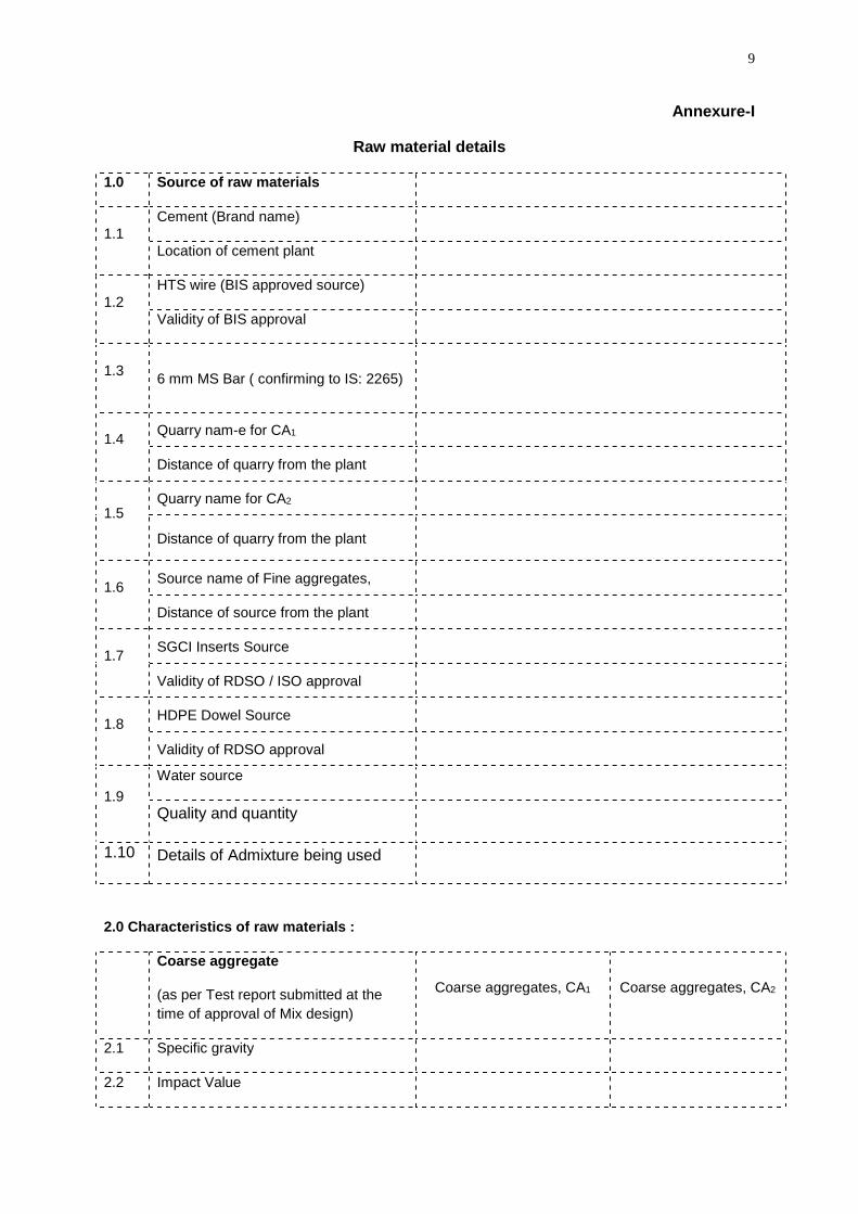
Annexure-I
Raw material details
1.0 Source of raw materials
1.1Cement (Brand name)
Location of cement plant
1.2HTS wire (BIS approved source)
Validity of BIS approval
1.3 6 mm MS Bar ( confirming to IS: 2265)
1.4 Quarry nam-e for CA1
Distance of quarry from the plant
1.5Quarry name for CA2
Distance of quarry from the plant
1.6 Source name of Fine aggregates,
Distance of source from the plant
1.7 SGCI Inserts Source
Validity of RDSO / ISO approval
1.8 HDPE Dowel Source
Validity of RDSO approval
1.9Water source
Quality and quantity
1.10 Details of Admixture being used
2.0 Characteristics of raw materials :
Coarse aggregate
(as per Test report submitted at thetime of approval of Mix design)
Coarse aggregates, CA1 Coarse aggregates, CA2
2.1 Specific gravity
2.2 Impact Value
10
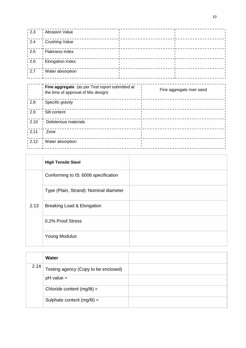
2.3 Abrasion Value
2.4 Crushing Value
2.5 Flakiness Index
2.6 Elongation Index
2.7 Water absorption
Fine aggregate (as per Test report submitted atthe time of approval of Mix design) Fine aggregate river sand
2.8 Specific gravity
2.9 Silt content
2.10 Deleterious materials
2.11 Zone
2.12 Water absorption
High Tensile Steel
2.13
Conforming to IS: 6006 specification
Type (Plain, Strand): Nominal diameter
Breaking Load & Elongation
0.2% Proof Stress
Young Modulus
Water
2.14 Testing agency (Copy to be enclosed)
pH value =
Chloride content (mg/lit) =
Sulphate content (mg/lit) =
11
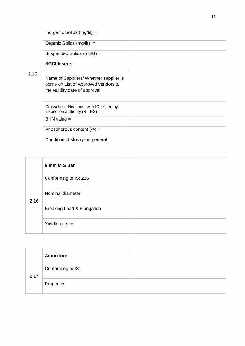
Inorganic Solids (mg/lit) =
Organic Solids (mg/lit) =
Suspended Solids (mg/lit) =
SGCI Inserts
2.15Name of Suppliers/ Whether supplier isborne on List of Approved vendors &the validity date of approval
Crosscheck Heat nos. with IC issued byInspection authority (RITES)
BHN value =
Phosphorous content (%) =
Condition of storage in general
6 mm M S Bar
2.16
Conforming to IS: 226
Nominal diameter
Breaking Load & Elongation
Yielding stress
Admixture
2.17
Conforming to IS:
Properties
12
Annexure-II
MAINTENANCE OF RECORDS AND DOCUMENTATION :
Following records shall be maintained for scrutiny at future dates.
1.0 Inventory of Raw materials:
1.1 Aggregates:
a) Coarse Aggregate (CA1) 20 to 10 mmb) Coarse Aggregate (CA2) 10 mm and down.c) Fine Aggregate (Sand)
Details of Receipt, Source, Date of receipt, Truck Nos., Quantity, Balance, Remarks aboutquality and signature.
1.2 H.T.S. ( IS: 6006) :Date of Receipt, Truck No., Nos. of Coils, Serial No. of each coil, Source (Name of the firm),Details of test certificate, quantity, shift-wise consumption, balance and remarks whether testcertificate is OK. Each lot shall bear a lot number and it should be mentioned in theproduction register to correlate, which HTS used in which sleeper.
1.3 Special Cement ( IRS:T-40):Date of receipt, Source, quantity, Shift-wise consumption, balance, whether Test Certificatereceived, Details of Lab Tests done at site, Consistency, Initial & Final setting time, Finenessand 7 days mortar cube strength. Each lot shall bear a lot number and it should be mentionedin the production register to correlate which cement used in which sleeper.
1.4 Inserts ( IRS: T- 46 ) :
Date of Receipt, Truck No., Quantity, Source (Name of manufacturer), Consumption, Balanceetc shall be recorded. Each lot shall bear a lot number and it should be mentioned in theproduction register to correlate which insert used in which sleeper.
1.5 Admixture:
Date of receipt, Source & conformance to IS codes, approval by RDSO, quantity, Shift-wiseconsumption, balance, whether Test Certificate received shall be recorded. Each lot shallbear a lot number and it should be mentioned in the production register to correlate withproduction of PSC sleepers.
2.0 Production Records:
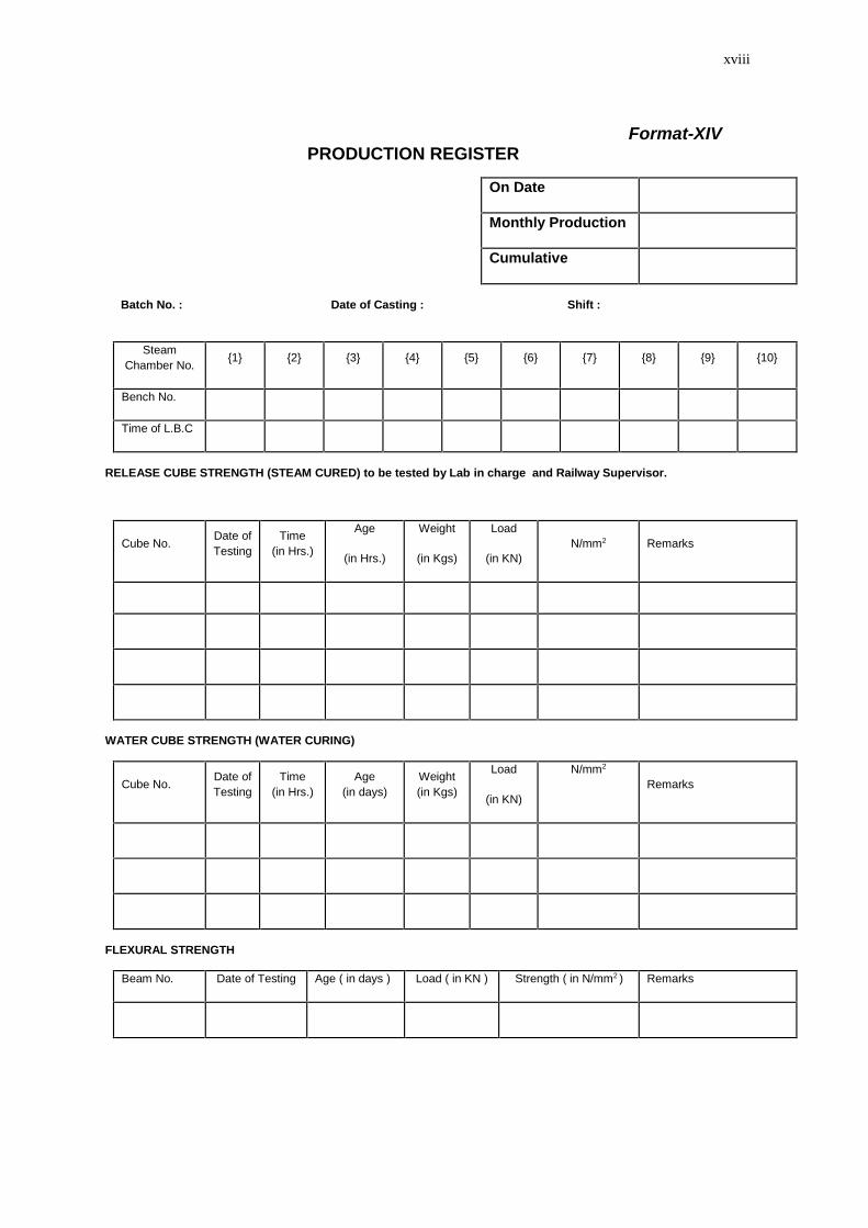
2.1 Production Register: Batch Nos., Nos. Cast in each shift, cumulative production, Bench Nos.,Cubes and sleeper testing details, Summary of Rejected and Usable sleepers shall berecorded in the printed register Daily production register shall be maintained for each designof sleepers separately (As per format no. XIV).
2.2 Tension Register: (As per format no. XII).
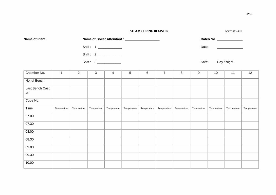
2.3 Steam Curing Records: (As per format no. XIII).
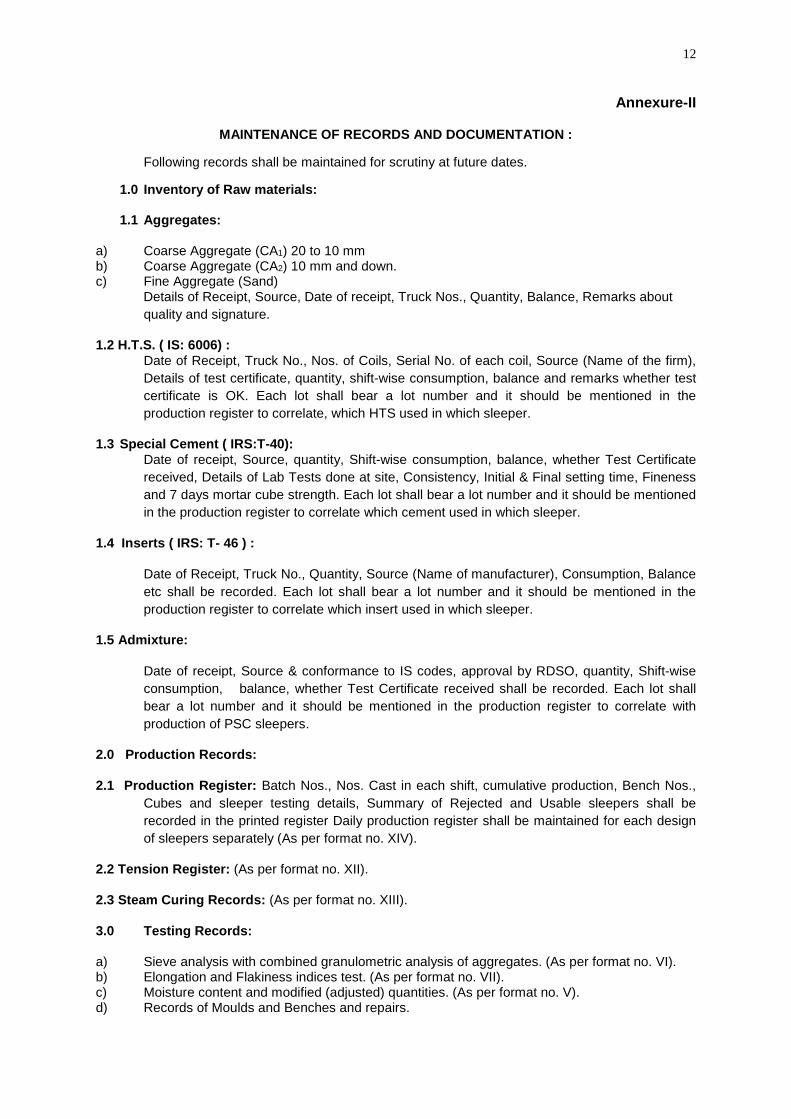
3.0 Testing Records:
a) Sieve analysis with combined granulometric analysis of aggregates. (As per format no. VI).b) Elongation and Flakiness indices test. (As per format no. VII).c) Moisture content and modified (adjusted) quantities. (As per format no. V).d) Records of Moulds and Benches and repairs.
13
e) Details of Pressure Gauges, Proving Rings and calibration of Pressure gauges.f) Steam curing and Release cube testing.g) Dimensional checking. (As per format no. XV).h) Proforma for individual batch production records.i) Proforma for monthly progress Report.j) Standard deviation and characteristic strength of
a) Release cubes.ii) 15 days water cured cubes.iii) Sleeper cracking loads / Rail Seat bottom and center top.
k) Dispatch Register.
4.0 Statistical Analysis & Report to RDSO:Statistical analysis along with calculations shall be submitted to RDSO every month in
i) Release cube strengthii) 15 days water cured cube strengthiii) Flexural Beam strengthiv) SBT resultsSimilar analysis shall be carried out for each month and a consolidated report shall be
submitted for a given financial year.
5.0 Calibration records:
The record shall be maintained as per Format-IX, X & XI for calibration of weigh batcher,Water meter, SBT machine, Concrete cube test machine, cement mortar cube testingmachine, Beam testing machine and tensioning jacks. The schedule is given in Para 10.6below.
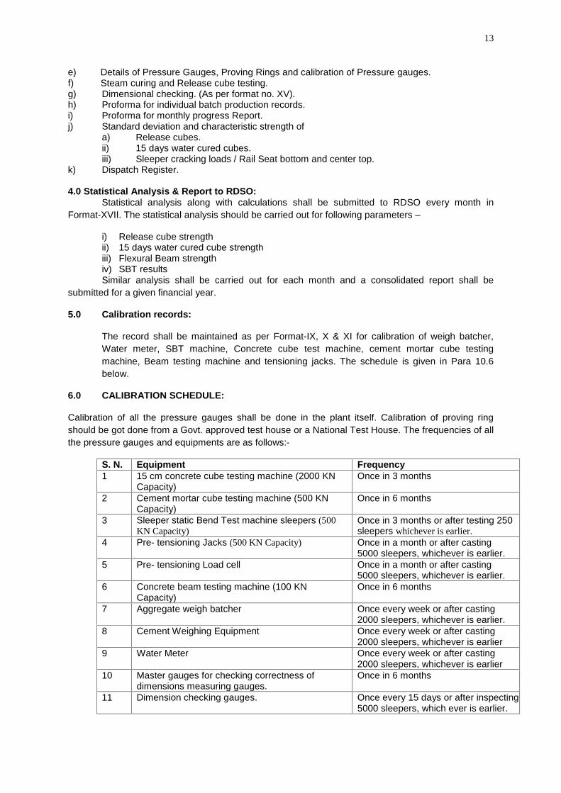
6.0 CALIBRATION SCHEDULE:
Calibration of all the pressure gauges shall be done in the plant itself. Calibration of proving ringshould be got done from a Govt. approved test house or a National Test House. The frequencies of allthe pressure gauges and equipments are as follows:-
S. N. Equipment Frequency1 15 cm concrete cube testing machine (2000 KN
Capacity)Once in 3 months
2 Cement mortar cube testing machine (500 KNCapacity)
Once in 6 months
3 Sleeper static Bend Test machine sleepers (500KN Capacity)
Once in 3 months or after testing 250sleepers whichever is earlier.
4 Pre- tensioning Jacks (500 KN Capacity) Once in a month or after casting5000 sleepers, whichever is earlier.
5 Pre- tensioning Load cell Once in a month or after casting5000 sleepers, whichever is earlier.
6 Concrete beam testing machine (100 KNCapacity)
Once in 6 months
7 Aggregate weigh batcher Once every week or after casting2000 sleepers, whichever is earlier.
8 Cement Weighing Equipment Once every week or after casting2000 sleepers, whichever is earlier
9 Water Meter Once every week or after casting2000 sleepers, whichever is earlier
10 Master gauges for checking correctness ofdimensions measuring gauges.
Once in 6 months
11 Dimension checking gauges. Once every 15 days or after inspecting5000 sleepers, which ever is earlier.
Format-XVII. The statistical analysis should be carried out for following parameters –
14
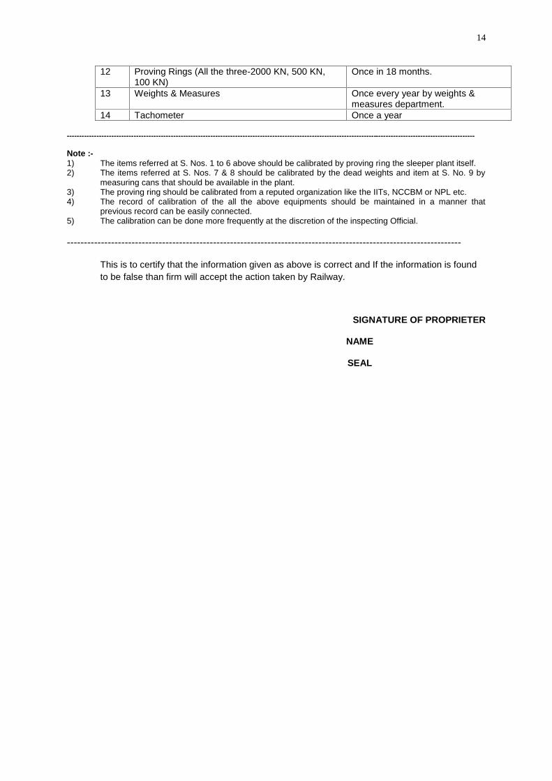
12 Proving Rings (All the three-2000 KN, 500 KN,100 KN)
Once in 18 months.
13 Weights & Measures Once every year by weights &measures department.
14 Tachometer Once a year
---------------------------------------------------------------------------------------------------------------------------------------------------------------------
Note :-1) The items referred at S. Nos. 1 to 6 above should be calibrated by proving ring the sleeper plant itself.2) The items referred at S. Nos. 7 & 8 should be calibrated by the dead weights and item at S. No. 9 by
measuring cans that should be available in the plant.3) The proving ring should be calibrated from a reputed organization like the IITs, NCCBM or NPL etc.4) The record of calibration of the all the above equipments should be maintained in a manner that
previous record can be easily connected.5) The calibration can be done more frequently at the discretion of the inspecting Official.
--------------------------------------------------------------------------------------------------------------------
This is to certify that the information given as above is correct and If the information is foundto be false than firm will accept the action taken by Railway.
SIGNATURE OF PROPRIETER
NAME
SEAL
i
Annexure III
FORMATS
This section contains different formats of recording results of various testing/measurements prescribed. The firm should have sufficient no of serially no Registersprinted for each format at all times. The formats should only be filled up by the minimumauthority mentioned in QAP. The relevant pages of registers pertaining to productionof sleepers being inspected must be scrutinized and signed by Railway officialresponsible for inspecting the sleepers. In addition to following formats Registersrequired as per contract condition including Site order register, Officer’s InspectionRegister and Over Sight Inspection compliance Register should be promptly filled upand presented to Railway Officials during inspection.
ii
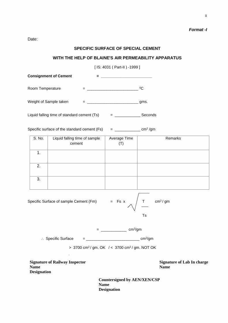
Format -I
Date:
SPECIFIC SURFACE OF SPECIAL CEMENT
WITH THE HELP OF BLAINE'S AIR PERMEABILITY APPARATUS
[ IS: 4031 ( Part-II ) -1999 ]
Consignment of Cement = ________________________
Room Temperature = ________________________ 0C
Weight of Sample taken = ________________________ gms.
Liquid falling time of standard cement (Ts) = ____________ Seconds
Specific surface of the standard cement (Fs) = ____________ cm2 /gm
S. No. Liquid falling time of samplecement
Average Time(T)
Remarks
1.
2.
3.
Specific Surface of sample Cement (Fm) = Fs x T cm2 / gm
Ts
= ____________ cm2/gm
Specific Surface = _________________________ cm2/gm
> 3700 cm2 / gm. OK / < 3700 cm2 / gm. NOT OK
[
Signature of Railway InspectorNameDesignation
Signature of Lab In chargeName
Countersigned by AEN/XEN/CSPNameDesignation
iii
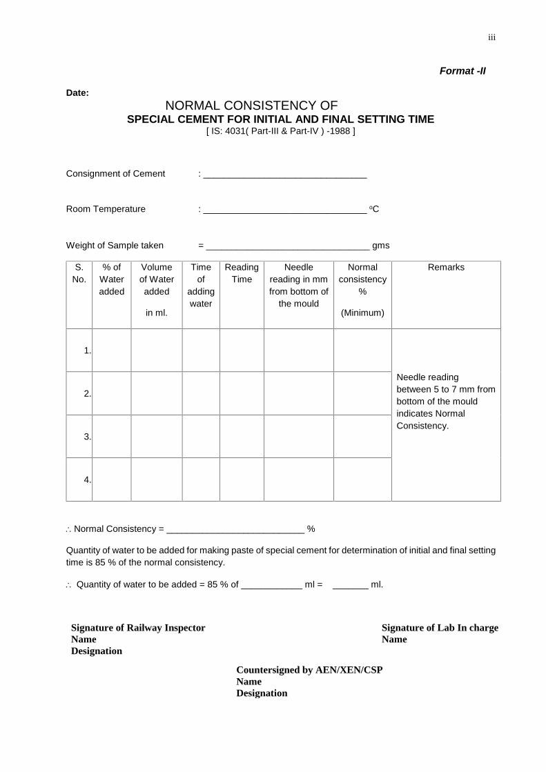
Format -II
Date:NORMAL CONSISTENCY OF
SPECIAL CEMENT FOR INITIAL AND FINAL SETTING TIME[ IS: 4031( Part-III & Part-IV ) -1988 ]
Consignment of Cement : ________________________________
Room Temperature : ________________________________ oC
Weight of Sample taken = ________________________________ gms
S.No.
% ofWateradded
Volumeof Wateradded
in ml.
Timeof
addingwater
ReadingTime
Needlereading in mmfrom bottom of
the mould
Normalconsistency
%
(Minimum)
Remarks
1.
Needle readingbetween 5 to 7 mm frombottom of the mouldindicates NormalConsistency.
2.
3.
4.
Normal Consistency = ___________________________ %
Quantity of water to be added for making paste of special cement for determination of initial and final settingtime is 85 % of the normal consistency.
Quantity of water to be added = 85 % of ____________ ml = _______ ml.
Signature of Railway InspectorNameDesignation
Signature of Lab In chargeName
Countersigned by AEN/XEN/CSPNameDesignation
iv
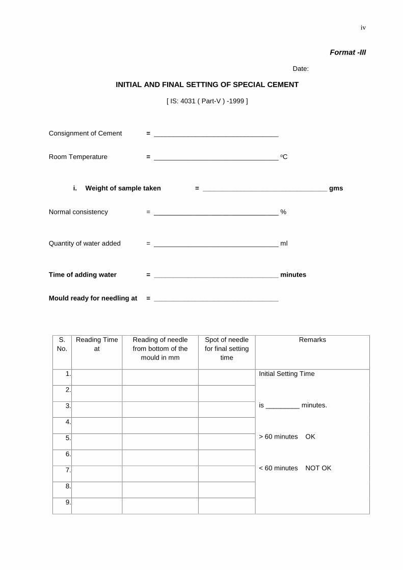
Format -III
Date:
INITIAL AND FINAL SETTING OF SPECIAL CEMENT
[ IS: 4031 ( Part-V ) -1999 ]
Consignment of Cement = _________________________________
Room Temperature = _________________________________ oC
i. Weight of sample taken = _________________________________ gms
Normal consistency = _________________________________ %
Quantity of water added = _________________________________ ml
Time of adding water = _________________________________ minutes
Mould ready for needling at = _________________________________
S.No.
Reading Timeat
Reading of needlefrom bottom of the
mould in mm
Spot of needlefor final setting
time
Remarks
1. Initial Setting Time
is _________ minutes.
> 60 minutes OK
< 60 minutes NOT OK
2.
3.
4.
5.
6.
7.
8.
9.
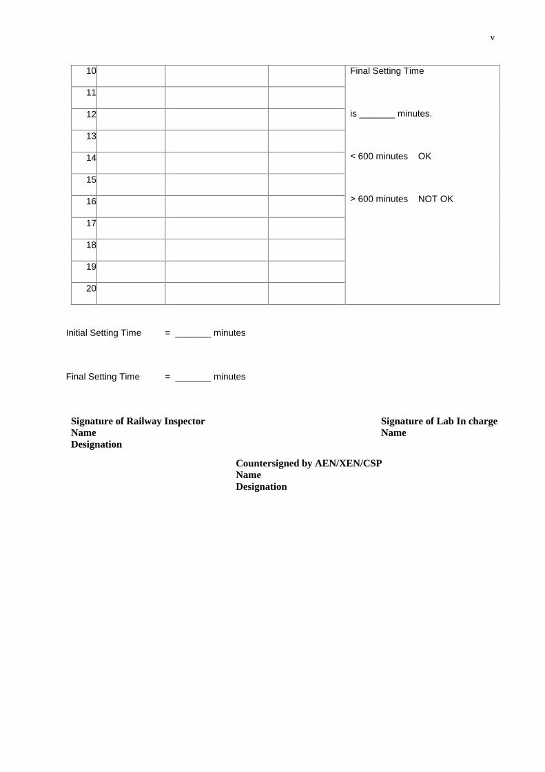
v
10. Final Setting Time
is _______ minutes.
11.
12.
13.
14.
15.
16.
17.
18.
19.
20.
Initial Setting Time = _______ minutes
Final Setting Time = _______ minutes
Signature of Railway InspectorNameDesignation
Signature of Lab In chargeName
Countersigned by AEN/XEN/CSPNameDesignation
< 600 minutes OK
> 600 minutes NOT OK
vi
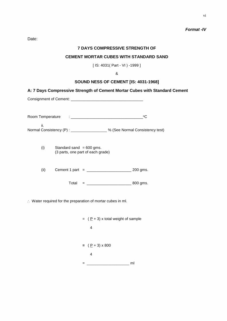
Format -IV
Date:
7 DAYS COMPRESSIVE STRENGTH OF
CEMENT MORTAR CUBES WITH STANDARD SAND
[ IS: 4031( Part - VI ) -1999 ]
&
SOUND NESS OF CEMENT [IS: 4031-1968]
A: 7 Days Compressive Strength of Cement Mortar Cubes with Standard Cement
Consignment of Cement: __________________________________
Room Temperature : __________________________________oC
ii.Normal Consistency (P) : _________________ % (See Normal Consistency test)
(i) Standard sand = 600 gms.(3 parts, one part of each grade)
(ii) Cement 1 part = _____________________ 200 gms.
Total = _____________________ 800 gms.
Water required for the preparation of mortar cubes in ml.
= ( P + 3) x total weight of sample
4
= ( P + 3) x 800
4
= ____________________ ml
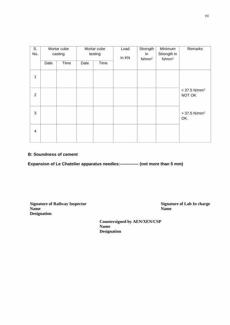
vii
S.No.
Mortar cubecasting
Mortar cubetesting
Load
In KN
Strengthin
N/mm2
MinimumStrength in
N/mm2
Remarks
Date Time Date Time
1
< 37.5 N/mm2
NOT OK
> 37.5 N/mm2
OK.
2
3
4
B: Soundness of cement
Expansion of Le Chatelier apparatus needles:------------- (not more than 5 mm)
Signature of Railway InspectorNameDesignation
Signature of Lab In chargeName
Countersigned by AEN/XEN/CSPNameDesignation
viii
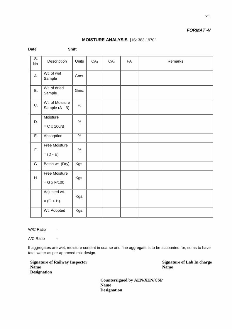
FORMAT -V
MOISTURE ANALYSIS [ IS: 383-1970 ]
Date Shift
S.No. Description Units CA1 CA2 FA Remarks
A. Wt. of wetSample Gms.
B. Wt. of driedSample Gms.
C. Wt. of MoistureSample (A - B) %
D.Moisture
= C x 100/B%
E. Absorption %
F.Free Moisture
= (D - E)%
G. Batch wt. (Dry) Kgs.
H.Free Moisture
= G x F/100Kgs.
Adjusted wt.
= (G + H)Kgs.
Wt. Adopted Kgs.
W/C Ratio =
A/C Ratio =
If aggregates are wet, moisture content in coarse and fine aggregate is to be accounted for, so as to havetotal water as per approved mix design.
Signature of Railway InspectorNameDesignation
Signature of Lab In chargeName
Countersigned by AEN/XEN/CSPNameDesignation
ix
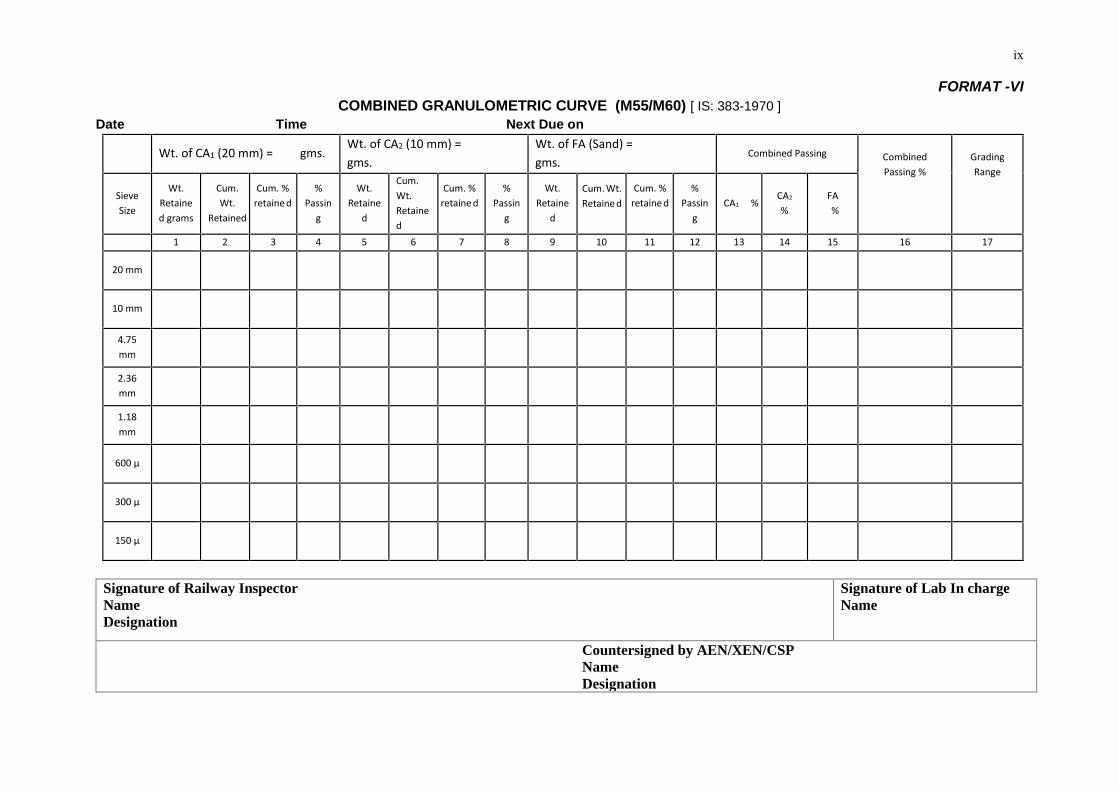
FORMAT -VICOMBINED GRANULOMETRIC CURVE (M55/M60) [ IS: 383-1970 ]
Date Time Next Due on
Wt. of CA1 (20 mm) = gms.Wt. of CA2 (10 mm) =gms.
Wt. of FA (Sand) =gms.
Combined Passing CombinedPassing %
GradingRange
SieveSize
Wt.Retained grams
Cum.Wt.
Retained
%Passin
g
Wt.Retaine
d
Cum.Wt.Retained
%Passin
g
Wt.Retaine
d
%Passin
gCA1 %
CA2
%FA%
1 2 3 4 5 6 7 8 9 10 11 12 13 14 15 16 17
20 mm
10 mm
4.75mm
2.36mm
1.18mm
600 µ
300 µ
150 µ
Signature of Railway InspectorNameDesignation
Signature of Lab In chargeName
Countersigned by AEN/XEN/CSPNameDesignation
Cum. %retaine d
Cum. %retaine d
Cum. %retaine d
Cum. Wt.Retaine d

x
x
Format –VII
A: DETERMINATION OF FLAKINESS INDEX [ IS: 2386 ( Part-I ) -1970 ]
SAMPLE TAKEN : COARSE AGGREGATE
Retained onI.S. sieve in
(mm)
Weight ofconsisting at
least 200 nos.(gm)
Gauge Width(mm)
Weight of aggregate ineach fraction in passing
through thicknessgauge (gm)
Remarks
1 2 3 4 5
20 W1 = 13.50 w1 =
10 W2 = 6.75 w2 =
4.75 W3 = 4.89 w3 =
Total W = w =
Flakiness Index = w / W x 100 = x 100 = %
As per IRS: T -39 the above result of flakiness index is less than 30%, hence satisfactory.
PROPOSED FORMAT:Format –VII
A: DETERMINATION OF FLAKINESS INDEX [IS: 2386 (Part-I) – 1963)SAMPLE TAKEN : COARSE AGGREGATERetained on I.S.Sieve in (mm) Gauge Width(mm) Weight of aggregatein each fraction inpassing throughthickness gauge(gm)
Remarks1 2 3 4 520 W1= 13.50 w1=16 W2= 10.80 w2=12.5 W3= 8.55 w3=10 W4= 6.75 w4=6.3 W5= w5Total W= w=Flakiness Index= w/Wx100= x100= %As per IRS:T-39 the above result of flakiness index is less than 30%.
Weight of aggregate (consisting atleast 200 Nos.) (gm)
xi
B: DETERMINATION OF ELONGATION INDEX
Retained onI.S. sieve in
(mm)
Weight of fractionconsisting at least
200 nos. (gm)
Gaugelengthsize(mm)
Weight of aggregate ineach fraction retained on
corresponding Gaugelength (mm)
Remarks
1 2 3 4 5
20 W1 = 40.50 w1 =
10 W2 = 20.20 w2 =
4.75 W3 = 14.70 w3 =
Total W = w =
Elongation Index = w / W x 100 = x 100 = %
As per IRS: T -39 the above result of Elongation index is less than 30%, hence satisfactory.
B: DETERMINATION OF ELONGATION INDEXRetained on I.S.Sieve in (mm) Gauge lengthsize (mm) Weight of aggregatein each fractionretained oncorresponding Gaugelength (mm)Remarks
1 2 3 4 520 W1= 40.50 w1=16 W2= 32.4 w2=12.5 W3= 25.6 w3=10 W4= 20.2 w4=6.3 W5= 14.7 w5Total W= w=Elongation Index= w/Wx100= x100= %As per IRS:T-39 the above result of Elongation index is less than 30%..Signature of Railway InspectorNameDesignation
Signature of Lab In chargeName
Countersigned by AEN/XEN/CSPNameDesignation
Weight of aggregate(consisting atleast 200 Nos.) (gm)
xii
FORMAT –VIII
A: DETERMINATION OF CRUSHING VALUE [ IS: 2386 ( Part-IV ) -1970 ]
Aggregate crushing value= (B/A) x100
Where, B= Weight of fraction passing appropriate sieve,
A= Weight of surface dry sample, when carried out as per provision of para: 2.4 IS:2386(Pt. IV)
A: DETERMINATION OF CRUSHING VALUE [IS :2386 (Part –IV) – 1963]Aggregate crushing value = (B/A) x 100Where B= Weight of fraction passing appropriate sieve,A= Weight of surface dry sample, when carried out as per provision of para :2.4 IS 2386 (pt.IV)Note: 1. For aggregates passing through 20mm sieve, 3.35mm sieve size for separatingfiner to be used.2. For aggregates passing through 10mm sieve, 1.70mm sieve size for separatingfiner to be used.
B: DETERMINATION OF IMPACT VALUE [ IS: 2386 ( Part-IV ) -1970 ]
Aggregate crushing value= (B/A) x100
Where, B= Weight of fraction passing 2.36mm IS sieve,
A= Weight of oven dry sample, when carried out as per provision of para: 4.4 IS:2386(Pt. IV)
C: DETERMINATION OF ABRASION VALUE [ IS: 2386 ( Part-IV ) -1970 ]
Aggregate crushing value= (B/A) x100
Where, B= Weight of fraction passing 1.7mm IS sieve,
A= Weight of oven dry sample, when carried out as per provision of para: 5.2 of IS:2386(Pt. IV)
Signature of Railway InspectorNameDesignation
Signature of Lab In chargeName
Signature by AEN/XEN/CSPNameDesignation
xiii
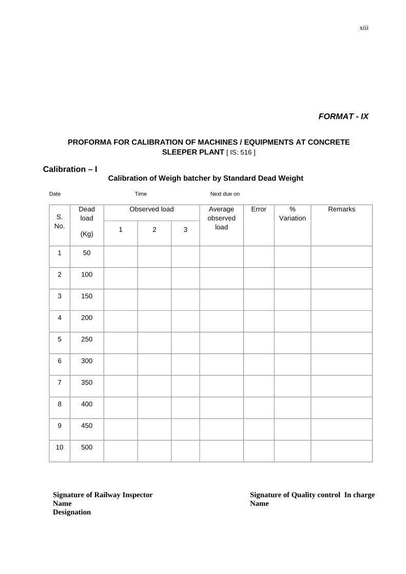
FORMAT - IX
PROFORMA FOR CALIBRATION OF MACHINES / EQUIPMENTS AT CONCRETESLEEPER PLANT [ IS: 516 ]
Calibration – ICalibration of Weigh batcher by Standard Dead Weight
Date Time Next due on
S.No.
Deadload
(Kg)
Observed load Averageobserved
load
Error %Variation
Remarks
1 2 3
1 50
2 100
3 150
4 200
5 250
6 300
7 350
8 400
9 450
10 500
Signature of Railway InspectorNameDesignation
Signature of Quality control In chargeName
xiv
Signature of AEN/XEN/CSPNameDesignation
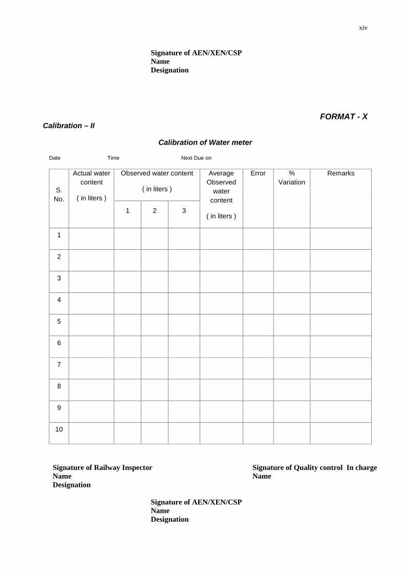
FORMAT - XCalibration – II
Calibration of Water meter
Date Time Next Due on
S.No.
Actual watercontent
( in liters )
Observed water content
( in liters )
AverageObserved
watercontent
( in liters )
Error %Variation
Remarks
1 2 3
1
2
3
4
5
6
7
8
9
10
Signature of Railway InspectorNameDesignation
Signature of Quality control In chargeName
Signature of AEN/XEN/CSPNameDesignation
xv
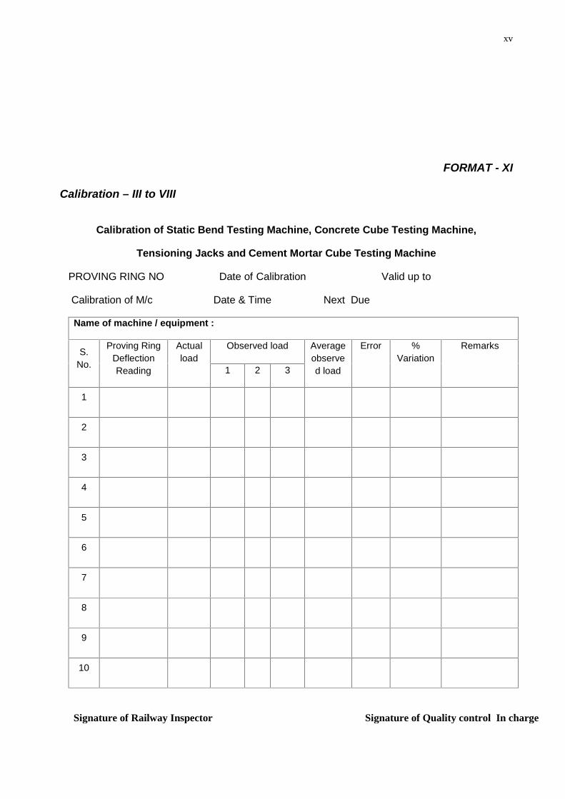
FORMAT - XI
Calibration – III to VIII
Calibration of Static Bend Testing Machine, Concrete Cube Testing Machine,
Tensioning Jacks and Cement Mortar Cube Testing Machine
PROVING RING NO Date of Calibration Valid up to
Calibration of M/c Date & Time Next Due
Name of machine / equipment :
S.No.
Proving RingDeflectionReading
Actualload
Observed load Averageobserved load
Error %Variation
Remarks
1 2 3
1
2
3
4
5
6
7
8
9
10
Signature of Railway Inspector Signature of Quality control In charge

xvi
NameDesignation
Name
Signature of AEN/XEN/CSPNameDesignation
17
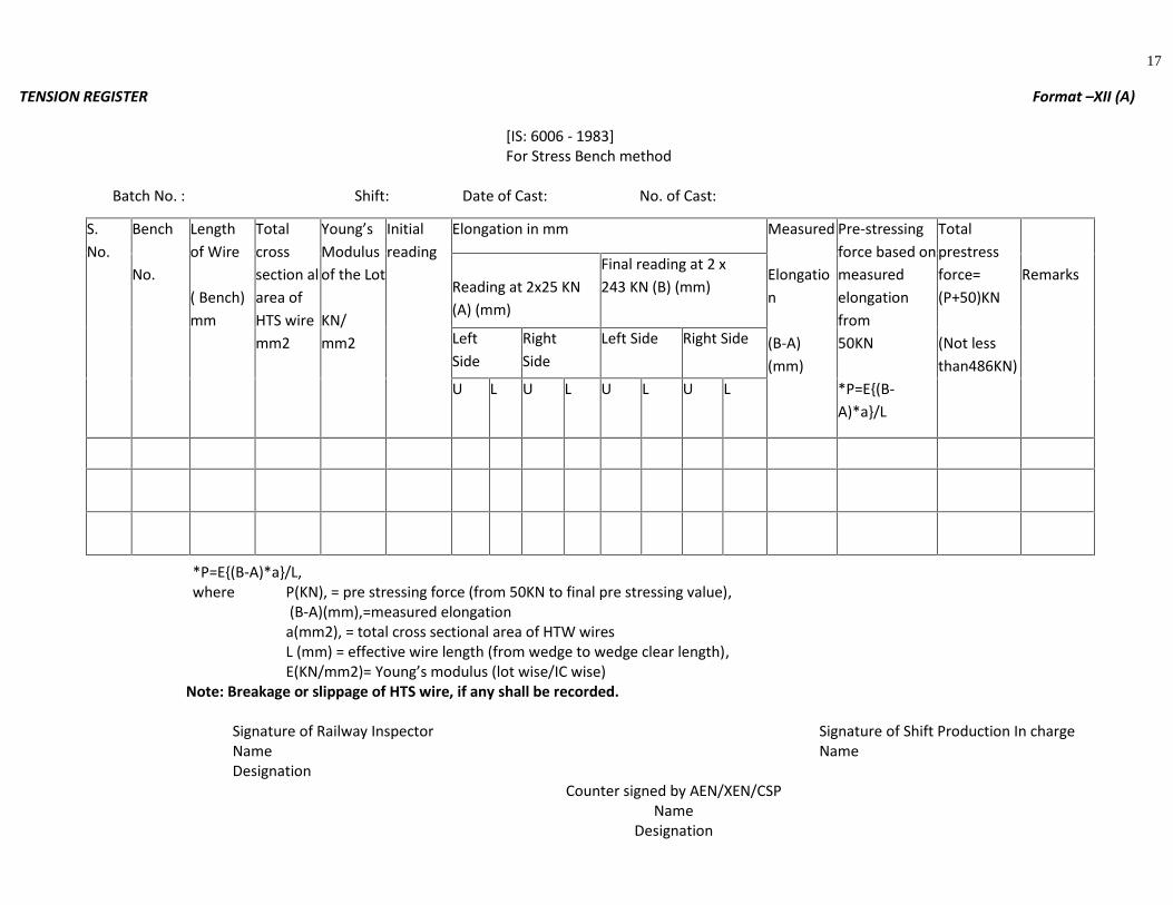
TENSION REGISTER Format –XII (A)
[IS: 6006 - 1983]For Stress Bench method
Batch No. : Shift: Date of Cast: No. of Cast:
*P=E{(B-A)*a}/L,where P(KN), = pre stressing force (from 50KN to final pre stressing value),
(B-A)(mm),=measured elongationa(mm2), = total cross sectional area of HTW wiresL (mm) = effective wire length (from wedge to wedge clear length),E(KN/mm2)= Young’s modulus (lot wise/IC wise)
Note: Breakage or slippage of HTS wire, if any shall be recorded.
Signature of Railway Inspector Signature of Shift Production In chargeName NameDesignation
Counter signed by AEN/XEN/CSPName
Designation
S.No.
Bench
No.
Lengthof Wire
( Bench)mm
Totalcrosssection alarea ofHTS wiremm2
Young’sModulusof the Lot
KN/mm2
Initialreading
Elongation in mm Measured
Elongation
(B-A)(mm)
Pre-stressingforce based onmeasuredelongationfrom50KN
*P=E{(B-A)*a}/L
Totalprestressforce=(P+50)KN
(Not lessthan486KN)
RemarksReading at 2x25 KN(A) (mm)
Final reading at 2 x243 KN (B) (mm)
LeftSide
RightSide
Left Side Right Side
U L U L U L U L
18
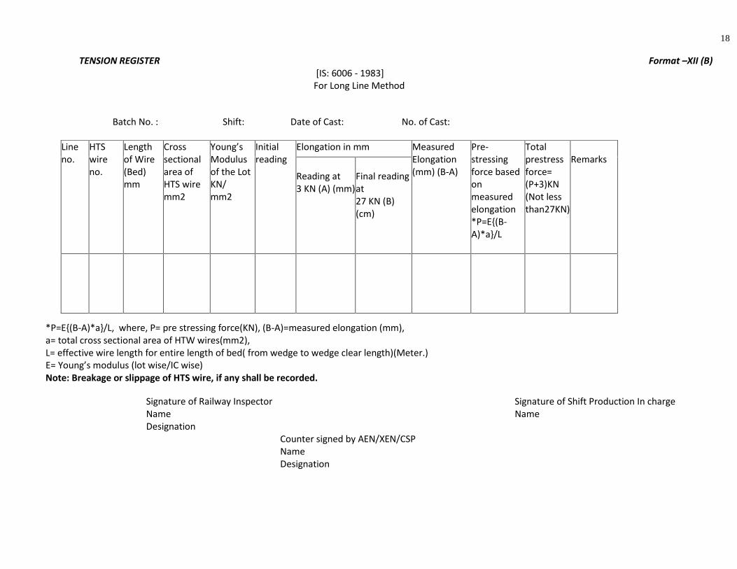
TENSION REGISTER Format –XII (B)[IS: 6006 - 1983]
For Long Line Method
Batch No. : Shift: Date of Cast: No. of Cast:
*P=E{(B-A)*a}/L, where, P= pre stressing force(KN), (B-A)=measured elongation (mm),a= total cross sectional area of HTW wires(mm2),L= effective wire length for entire length of bed( from wedge to wedge clear length)(Meter.)E= Young’s modulus (lot wise/IC wise)Note: Breakage or slippage of HTS wire, if any shall be recorded.
Signature of Railway Inspector Signature of Shift Production In chargeName NameDesignation
Counter signed by AEN/XEN/CSPNameDesignation
Lineno.
HTSwireno.
Lengthof Wire(Bed)mm
Crosssectionalarea ofHTS wiremm2
Young’sModulusof the LotKN/mm2
Initialreading
Elongation in mm MeasuredElongation(mm) (B-A)
Pre-stressingforce basedonmeasuredelongation*P=E{(B-A)*a}/L
Totalprestressforce=(P+3)KN(Not lessthan27KN)
Remarks
Reading at3 KN (A) (mm)
Final readingat27 KN (B)(cm)

xvi

xvii
xviii
STEAM CURING REGISTER Format -XIII
Name of Plant: Name of Boiler Attendant : ___________________ Batch No. ______________
Shift : 1 _____________ Date: ______________
Shift : 2 _____________
Shift : 3 _____________ Shift: Day / Night
Chamber No. 1 2 3 4 5 6 7 8 9 10 11 12
No. of Bench
Last Bench Castat
Cube No.
Time Temperature Temperature Temperature Temperature Temperature Temperature Temperature Temperature Temperature Temperature Temperature Temperature
07.00
07.30
08.00
08.30
09.00
09.30
10.00
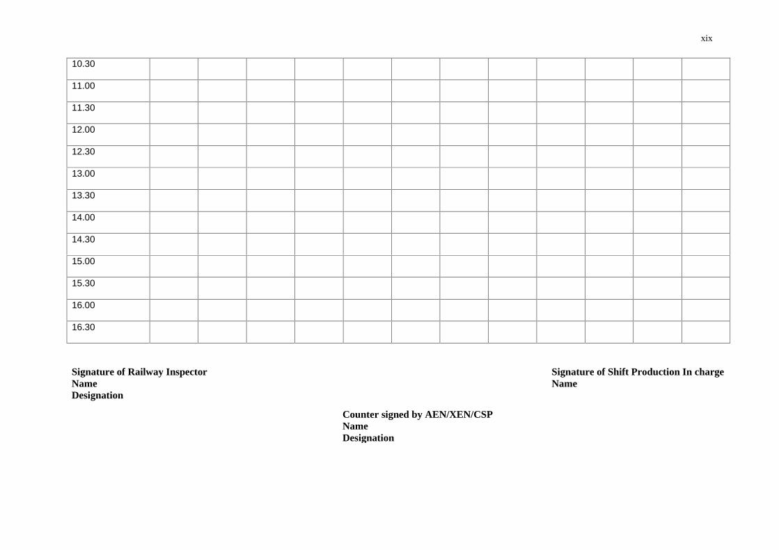
xix
10.30
11.00
11.30
12.00
12.30
13.00
13.30
14.00
14.30
15.00
15.30
16.00
16.30
Signature of Railway InspectorNameDesignation
Signature of Shift Production In chargeName
Counter signed by AEN/XEN/CSPNameDesignation
xviii
Format-XIVPRODUCTION REGISTER
On Date
Monthly Production
Cumulative
Batch No. : Date of Casting : Shift :
SteamChamber No. {1} {2} {3} {4} {5} {6} {7} {8} {9} {10}
Bench No.
Time of L.B.C
RELEASE CUBE STRENGTH (STEAM CURED) to be tested by Lab in charge and Railway Supervisor.
Cube No. Date ofTesting
Time(in Hrs.)
Age
(in Hrs.)
Weight
(in Kgs)
Load
(in KN)N/mm2 Remarks
WATER CUBE STRENGTH (WATER CURING)
Cube No. Date ofTesting
Time(in Hrs.)
Age(in days)
Weight(in Kgs)
Load
(in KN)
N/mm2
Remarks
FLEXURAL STRENGTH
Beam No. Date of Testing Age ( in days ) Load ( in KN ) Strength ( in N/mm2 ) Remarks
xix
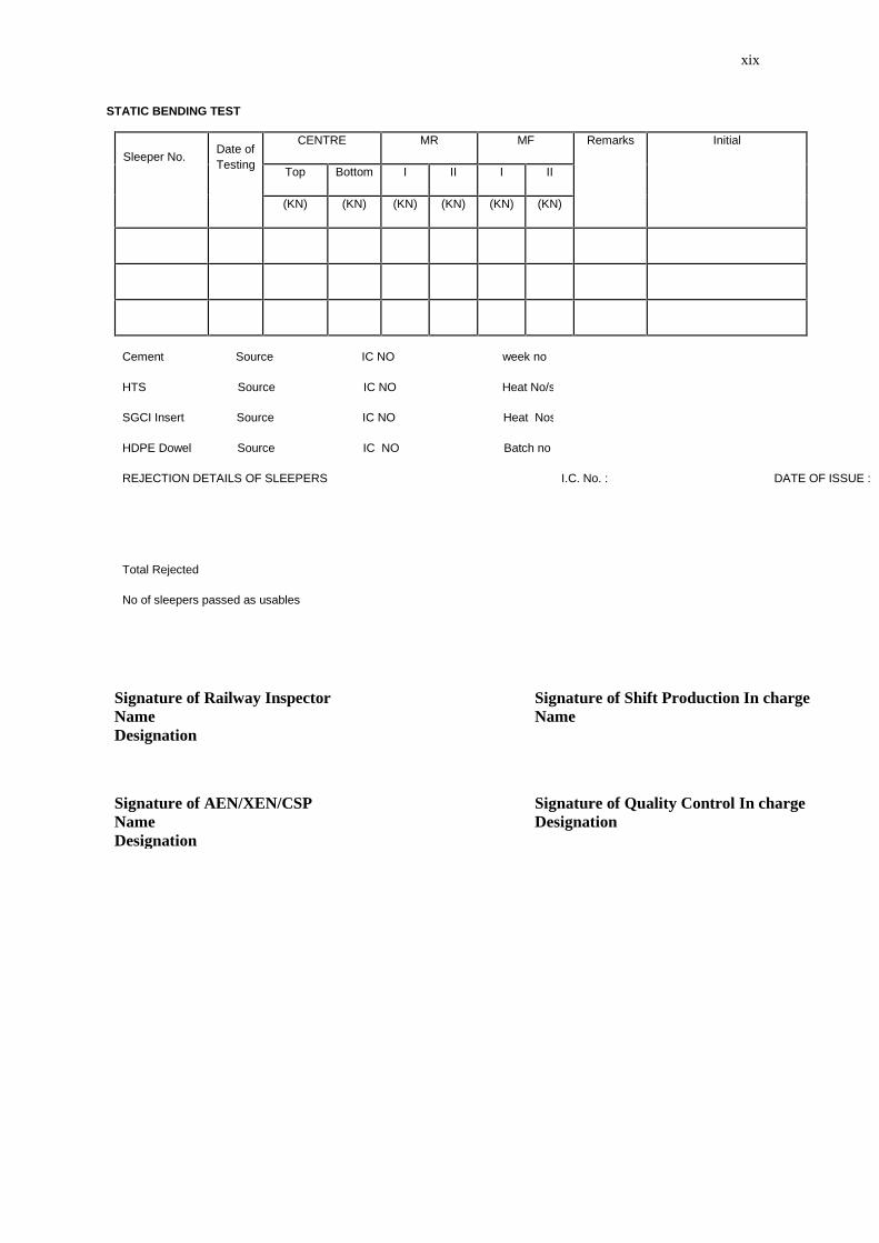
STATIC BENDING TEST
Sleeper No. Date ofTesting
CENTRE MR MF Remarks Initial
Top Bottom I II I II
(KN) (KN) (KN) (KN) (KN) (KN)
Cement Source IC NO week no
HTS Source IC NO Heat No/s
SGCI Insert Source IC NO Heat Nos
HDPE Dowel Source IC NO Batch no
REJECTION DETAILS OF SLEEPERS I.C. No. : DATE OF ISSUE :
Total Rejected
No of sleepers passed as usables
Signature of Railway InspectorNameDesignation
Signature of Shift Production In chargeName
Signature of AEN/XEN/CSPNameDesignation
Signature of Quality Control In chargeDesignation
xx
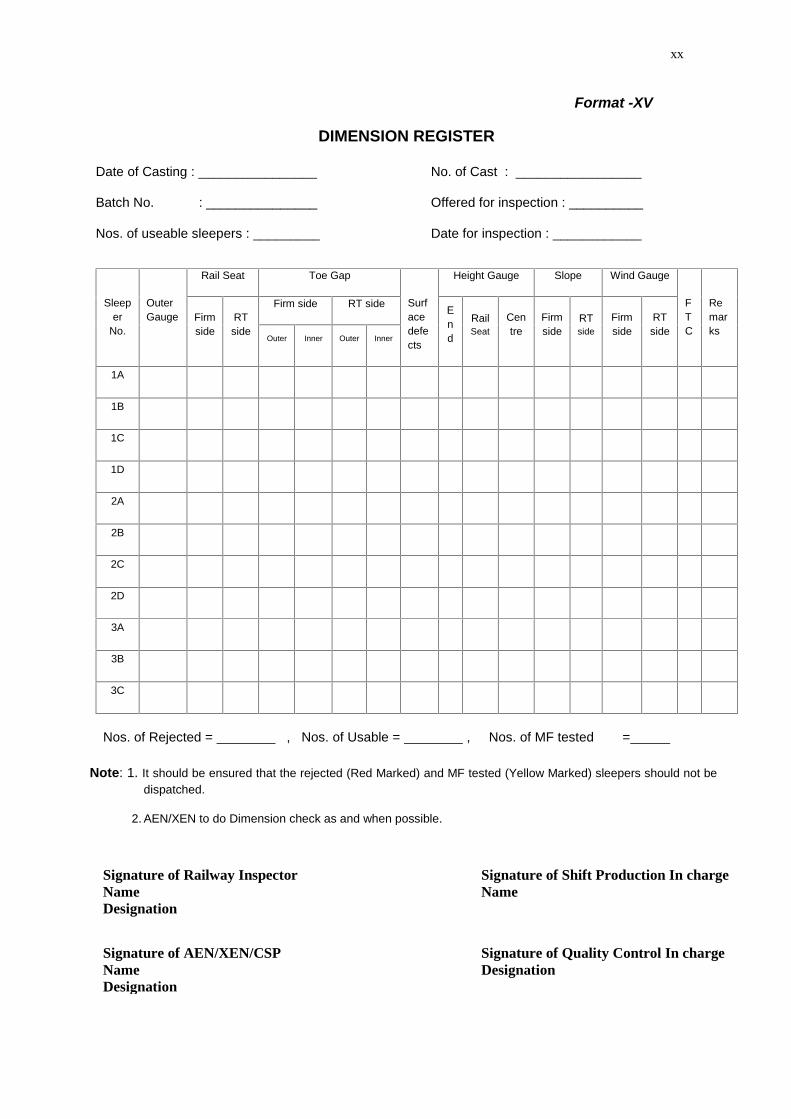
Format -XV
DIMENSION REGISTER
Date of Casting : ________________ No. of Cast : _________________
Batch No. : _______________ Offered for inspection : __________
Nos. of useable sleepers : _________ Date for inspection : ____________
Sleeper
No.
OuterGauge
Rail Seat Toe Gap
Surfacedefects
Height Gauge Slope Wind Gauge
FTC
Remarks
Firmside
RTside
Firm side RT side End
RailSeat
Centre
Firmside
RTside
Firmside
RTside
Outer Inner Outer Inner
1A
1B
1C
1D
2A
2B
2C
2D
3A
3B
3C
Nos. of Rejected = , Nos. of Usable = , Nos. of MF tested =
Note: 1. It should be ensured that the rejected (Red Marked) and MF tested (Yellow Marked) sleepers should not bedispatched.
2. AEN/XEN to do Dimension check as and when possible.
Signature of Railway InspectorNameDesignation
Signature of Shift Production In chargeName
Signature of AEN/XEN/CSPNameDesignation
Signature of Quality Control In chargeDesignation
xxi
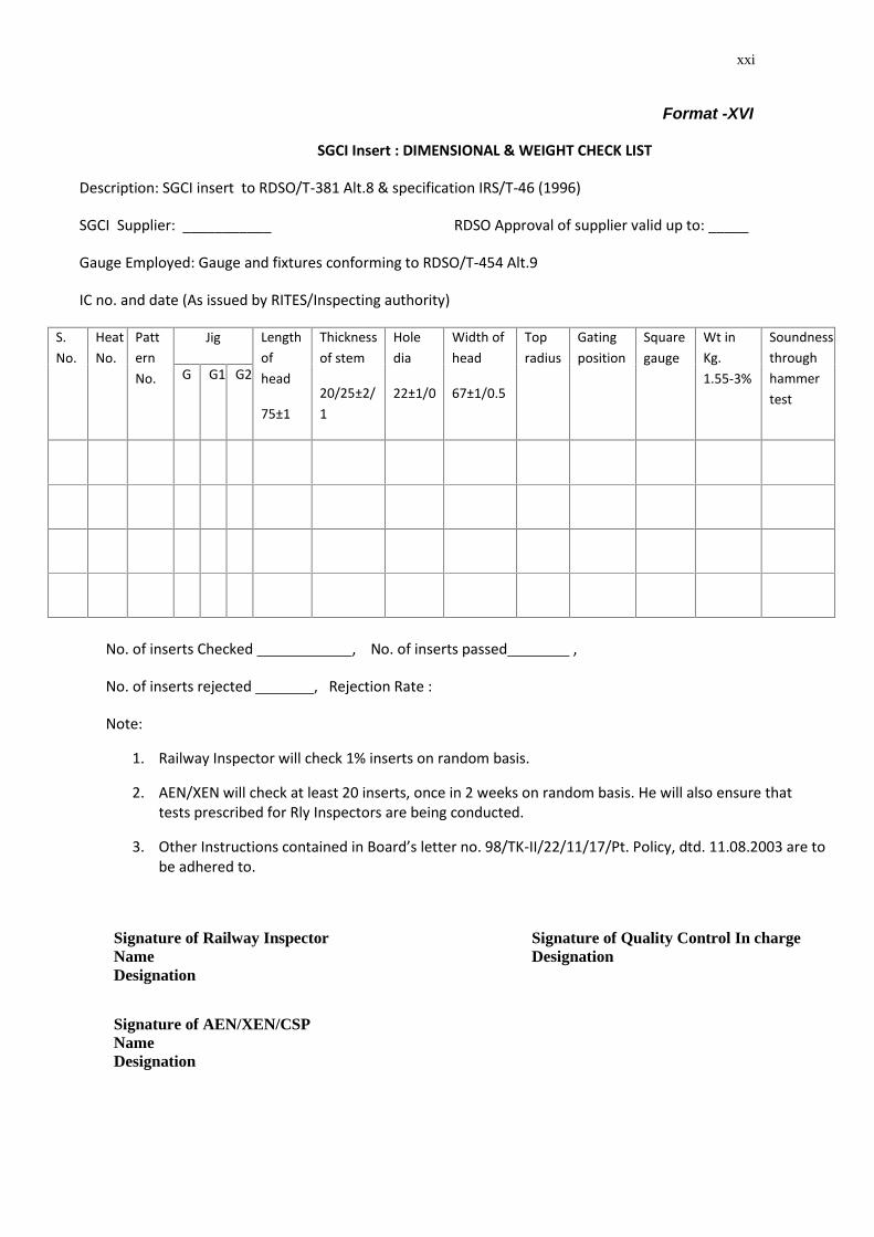
Format -XVI
SGCI Insert : DIMENSIONAL & WEIGHT CHECK LIST
Description: SGCI insert to RDSO/T-381 Alt.8 & specification IRS/T-46 (1996)
SGCI Supplier: ___________ RDSO Approval of supplier valid up to: _____
Gauge Employed: Gauge and fixtures conforming to RDSO/T-454 Alt.9
IC no. and date (As issued by RITES/Inspecting authority)
S.No.
HeatNo.
PatternNo.
Jig Lengthofhead
75±1
Thicknessof stem
20/25±2/1
Holedia
22±1/0
Width ofhead
67±1/0.5
Topradius
Gatingposition
Squaregauge
Wt inKg.1.55-3%
Soundnessthroughhammertest
G G1 G2
No. of inserts Checked , No. of inserts passed ,
No. of inserts rejected , Rejection Rate :
Note:
1. Railway Inspector will check 1% inserts on random basis.
2. AEN/XEN will check at least 20 inserts, once in 2 weeks on random basis. He will also ensure thattests prescribed for Rly Inspectors are being conducted.
3. Other Instructions contained in Board’s letter no. 98/TK-II/22/11/17/Pt. Policy, dtd. 11.08.2003 are tobe adhered to.
Signature of Railway InspectorNameDesignation
Signature of Quality Control In chargeDesignation
Signature of AEN/XEN/CSPNameDesignation
xxii
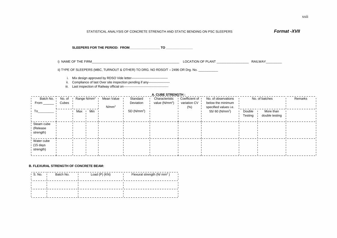
STATISTICAL ANALYSIS OF CONCRETE STRENGTH AND STATIC BENDING ON PSC SLEEPERS Format -XVII
SLEEPERS FOR THE PERIOD: FROM_________________ TO _______________
i) NAME OF THE FIRM_________________________________________________ LOCATION OF PLANT __________________ RAILWAY_________
ii) TYPE OF SLEEPERS (MBC, TURNOUT & OTHER) TO DRG. NO RDSO/T – 2496 OR Drg. No. ___________
i. Mix design approved by RDSO Vide letter----------------------------------ii. Compliance of last Over site inspection pending if any--------------------iii. Last inspection of Railway official on------------------------------------------
A. CUBE STRENGTH :Batch No.
From ______
To_________
No. ofCubes
Range N/mm2 Mean Value
N/mm2
StandardDeviation
SD (N/mm2)
Characteristicvalue (N/mm2)
Coefficient ofvariation CV
(%)
No. of observationsbelow the minimumspecified values i.e.
55/ 60 (N/mm2)
No. of batches Remarks
Max Min DoubleTesting
More thandouble testing
Steam cube(Releasestrength)
Water cube(15 daysstrength)
B. FLEXURAL STRENGTH OF CONCRETE BEAM:
S. No. Batch No. Load (P) (KN) Flexural strength (N/ mm2 )
xxiii
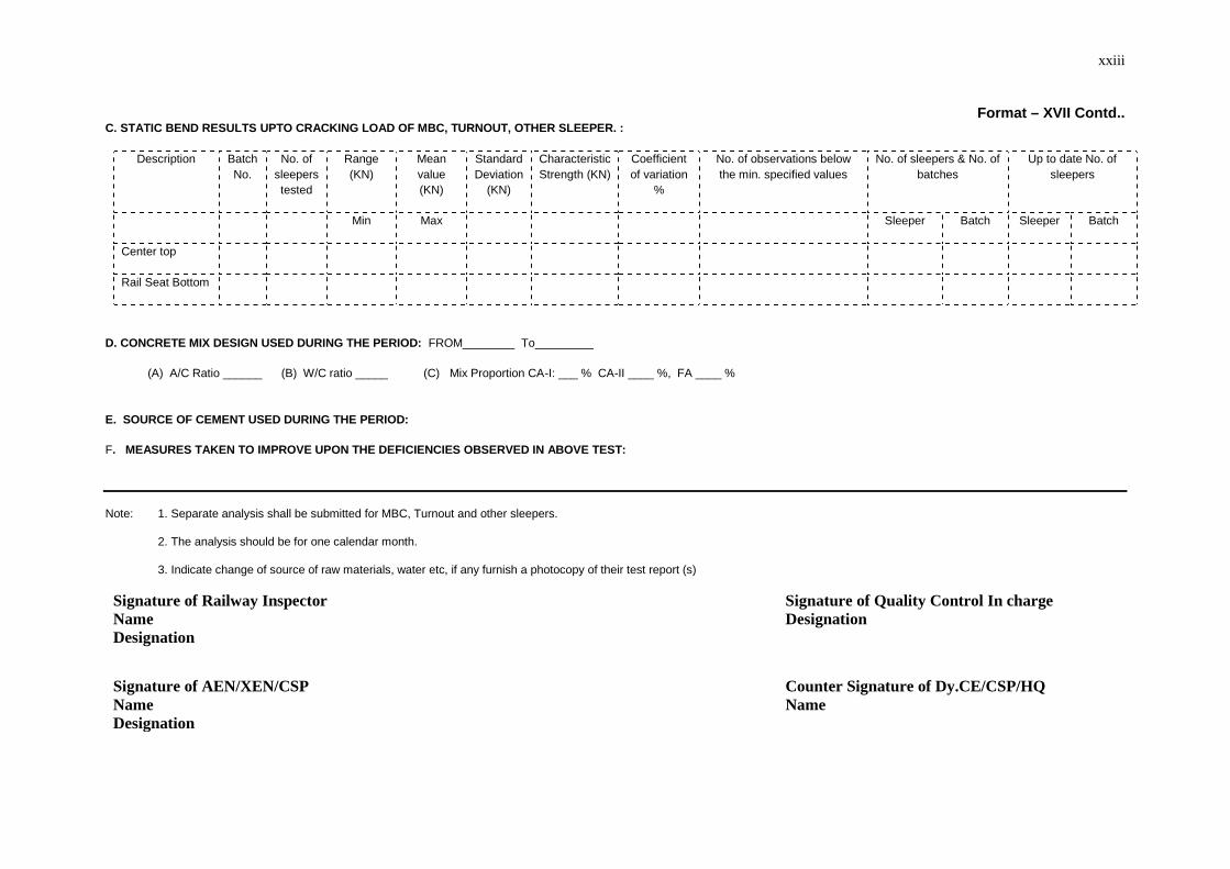
Format – XVII Contd..C. STATIC BEND RESULTS UPTO CRACKING LOAD OF MBC, TURNOUT, OTHER SLEEPER. :
Description BatchNo.
No. ofsleeperstested
Range(KN)
Meanvalue(KN)
StandardDeviation
(KN)
CharacteristicStrength (KN)
Coefficientof variation
%
No. of observations belowthe min. specified values
No. of sleepers & No. ofbatches
Up to date No. ofsleepers
Min Max Sleeper Batch Sleeper Batch
Center top
Rail Seat Bottom
D. CONCRETE MIX DESIGN USED DURING THE PERIOD: FROM________ To_________
(A) A/C Ratio ______ (B) W/C ratio _____ (C) Mix Proportion CA-I: ___ % CA-II ____ %, FA ____ %
E. SOURCE OF CEMENT USED DURING THE PERIOD:
F. MEASURES TAKEN TO IMPROVE UPON THE DEFICIENCIES OBSERVED IN ABOVE TEST:
Note: 1. Separate analysis shall be submitted for MBC, Turnout and other sleepers.
2. The analysis should be for one calendar month.
3. Indicate change of source of raw materials, water etc, if any furnish a photocopy of their test report (s)
Signature of Railway InspectorNameDesignation
Signature of Quality Control In chargeDesignation
Signature of AEN/XEN/CSPNameDesignation
Counter Signature of Dy.CE/CSP/HQName

xxiv
xxiv
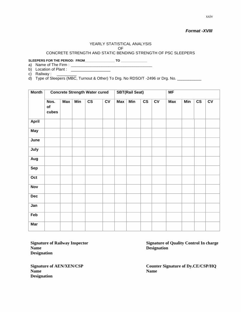
Format -XVIII
YEARLY STATISTICAL ANALYSISOF
CONCRETE STRENGTH AND STATIC BENDING STRENGTH OF PSC SLEEPERS
SLEEPERS FOR THE PERIOD: FROM_________________ TO _______________a) Name of The Firm : _____________________________________b) Location of Plant : __________________c) Railway : _________d) Type of Sleepers (MBC, Turnout & Other) To Drg. No RDSO/T -2496 or Drg. No. ___________
Month Concrete Strength Water cured SBT(Rail Seat) MF
Nos.ofcubes
Max Min CS CV Max Min CS CV Max Min CS CV
April
May
June
July
Aug
Sep
Oct
Nov
Dec
Jan
Feb
Mar
Signature of Railway InspectorNameDesignation
Signature of Quality Control In chargeDesignation
Signature of AEN/XEN/CSPNameDesignation
Counter Signature of Dy.CE/CSP/HQName
xxv
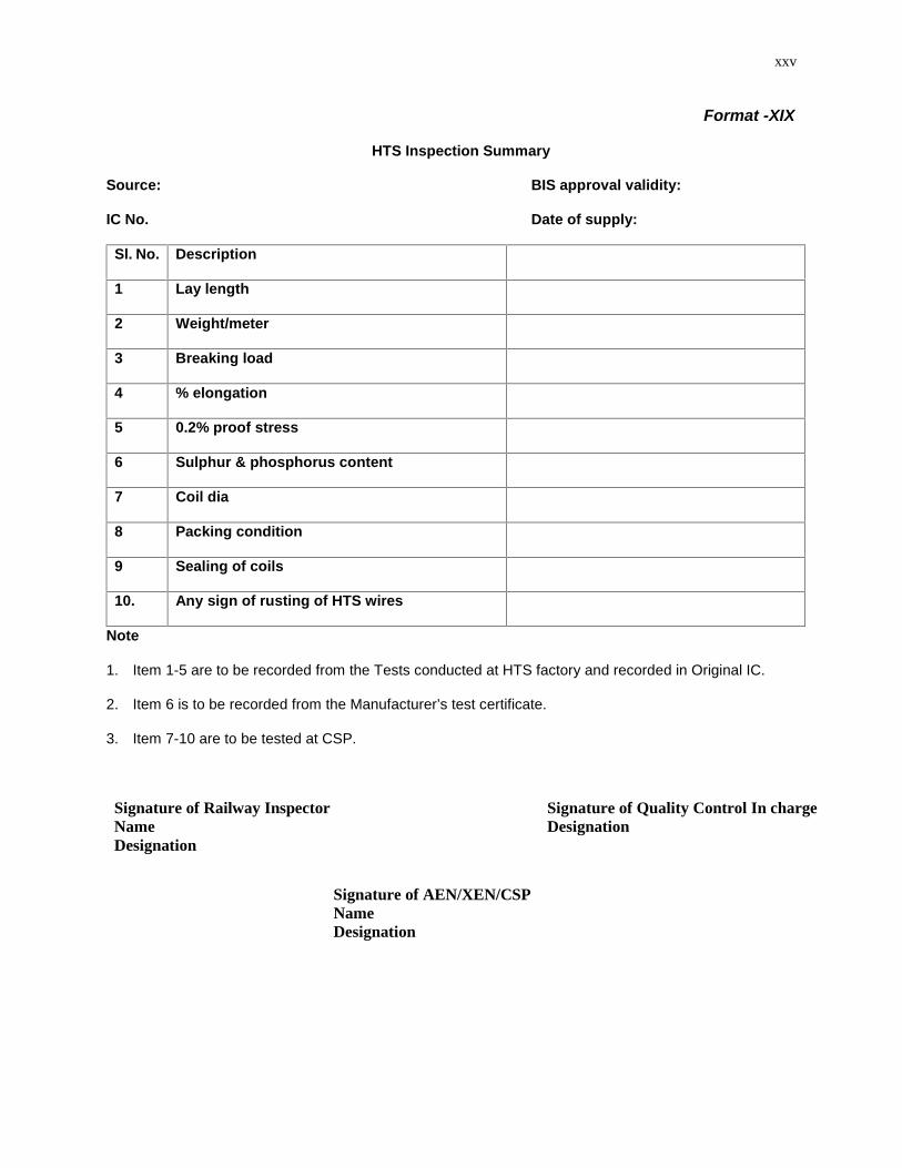
Format -XIX
HTS Inspection Summary
Source: BIS approval validity:
IC No. Date of supply:
Sl. No. Description
1 Lay length
2 Weight/meter
3 Breaking load
4 % elongation
5 0.2% proof stress
6 Sulphur & phosphorus content
7 Coil dia
8 Packing condition
9 Sealing of coils
10. Any sign of rusting of HTS wires
Note
1. Item 1-5 are to be recorded from the Tests conducted at HTS factory and recorded in Original IC.
2. Item 6 is to be recorded from the Manufacturer’s test certificate.
3. Item 7-10 are to be tested at CSP.
Signature of Railway InspectorNameDesignation
Signature of Quality Control In chargeDesignation
Signature of AEN/XEN/CSPNameDesignation
xxvi
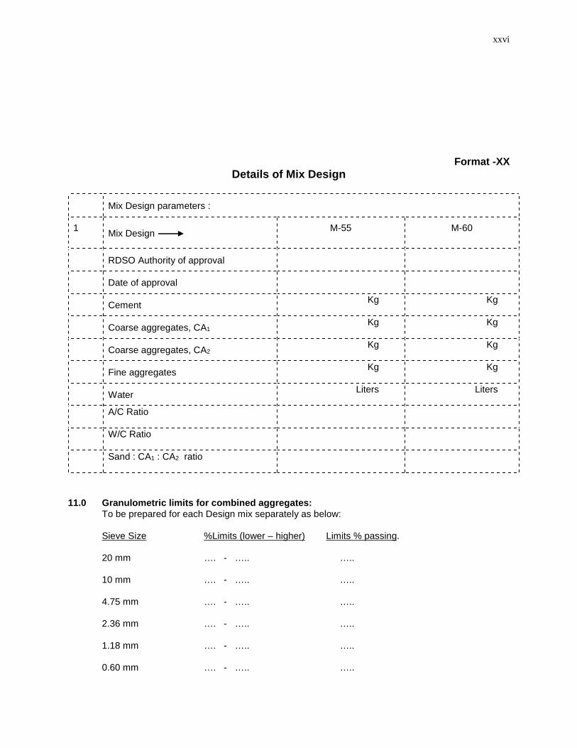
Format -XXDetails of Mix Design
Mix Design parameters :
1 Mix Design M-55 M-60
RDSO Authority of approval
Date of approval
Cement Kg Kg
Coarse aggregates, CA1Kg Kg
Coarse aggregates, CA2Kg Kg
Fine aggregates Kg Kg
Water Liters Liters
A/C Ratio
W/C Ratio
Sand : CA1 : CA2 ratio
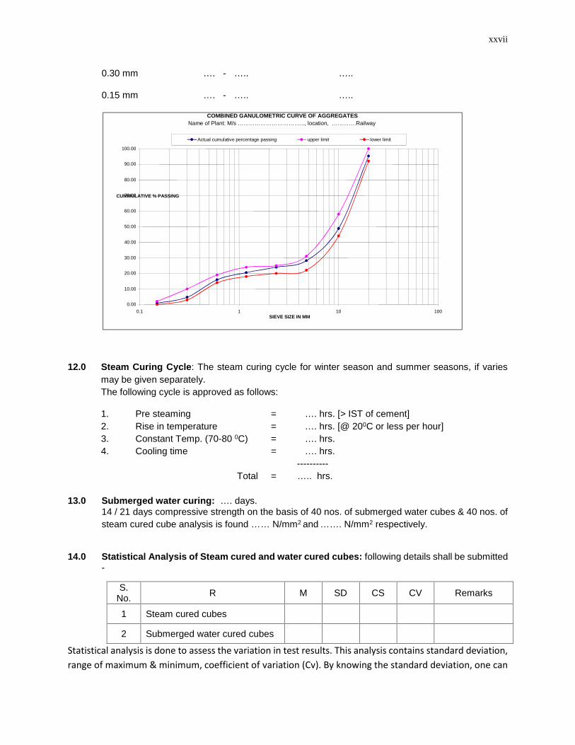
11.0 Granulometric limits for combined aggregates:To be prepared for each Design mix separately as below:
Sieve Size %Limits (lower – higher) Limits % passing.
20 mm …. - ….. …..
10 mm …. - ….. …..
4.75 mm …. - ….. …..
2.36 mm …. - ….. …..
1.18 mm …. - ….. …..
0.60 mm …. - ….. …..
xxvii
0.30 mm …. - ….. …..
0.15 mm …. - ….. …..
12.0 Steam Curing Cycle: The steam curing cycle for winter season and summer seasons, if variesmay be given separately.The following cycle is approved as follows:
1. Pre steaming = …. hrs. [> IST of cement]2. Rise in temperature = …. hrs. [@ 200C or less per hour]3. Constant Temp. (70-80 0C) = …. hrs.4. Cooling time = …. hrs.
----------Total = ….. hrs.
13.0 Submerged water curing: …. days.14 / 21 days compressive strength on the basis of 40 nos. of submerged water cubes & 40 nos. ofsteam cured cube analysis is found …… N/mm2 and ……. N/mm2 respectively.
14.0 Statistical Analysis of Steam cured and water cured cubes: following details shall be submitted-
S.No. R M SD CS CV Remarks
1 Steam cured cubes
2 Submerged water cured cubes
Statistical analysis is done to assess the variation in test results. This analysis contains standard deviation,range of maximum & minimum, coefficient of variation (Cv). By knowing the standard deviation, one can
COMBINED GANULOMETRIC CURVE OF AGGREGATESName of Plant: M/s ……………………………..., location, ………….Railway
0.00
10.00
20.00
30.00
40.00
50.00
60.00
70.00
80.00
90.00
100.00
0.1 1 10 100SIEVE SIZE IN MM
CUMMULATIVE % PASSING
Actual cumulative percentage passing upper limit lower limit
xxviii
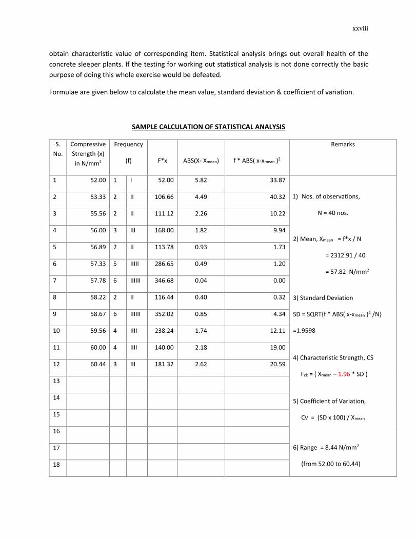
obtain characteristic value of corresponding item. Statistical analysis brings out overall health of theconcrete sleeper plants. If the testing for working out statistical analysis is not done correctly the basicpurpose of doing this whole exercise would be defeated.
Formulae are given below to calculate the mean value, standard deviation & coefficient of variation.
SAMPLE CALCULATION OF STATISTICAL ANALYSIS
S.No.
CompressiveStrength (x)in N/mm2
Frequency
(f) F*x ABS(X- Xmean) f * ABS( x-xmean )2
Remarks
1 52.00 1 I 52.00 5.82 33.87
1) Nos. of observations,
N = 40 nos.
2) Mean, Xmean = f*x / N
= 2312.91 / 40
= 57.82 N/mm2
3) Standard Deviation
SD = SQRT{f * ABS( x-xmean )2 /N}
=1.9598
4) Characteristic Strength, CS
Fck = ( Xmean – 1.96 * SD )
5) Coefficient of Variation,
Cv = (SD x 100) / Xmean
6) Range = 8.44 N/mm2
(from 52.00 to 60.44)
2 53.33 2 II 106.66 4.49 40.32
3 55.56 2 II 111.12 2.26 10.22
4 56.00 3 III 168.00 1.82 9.94
5 56.89 2 II 113.78 0.93 1.73
6 57.33 5 IIIII 286.65 0.49 1.20
7 57.78 6 IIIIII 346.68 0.04 0.00
8 58.22 2 II 116.44 0.40 0.32
9 58.67 6 IIIIII 352.02 0.85 4.34
10 59.56 4 IIII 238.24 1.74 12.11
11 60.00 4 IIII 140.00 2.18 19.00
12 60.44 3 III 181.32 2.62 20.59
13
14
15
16
17
18
xxix
19
20
21
22
23
24
25
..
..
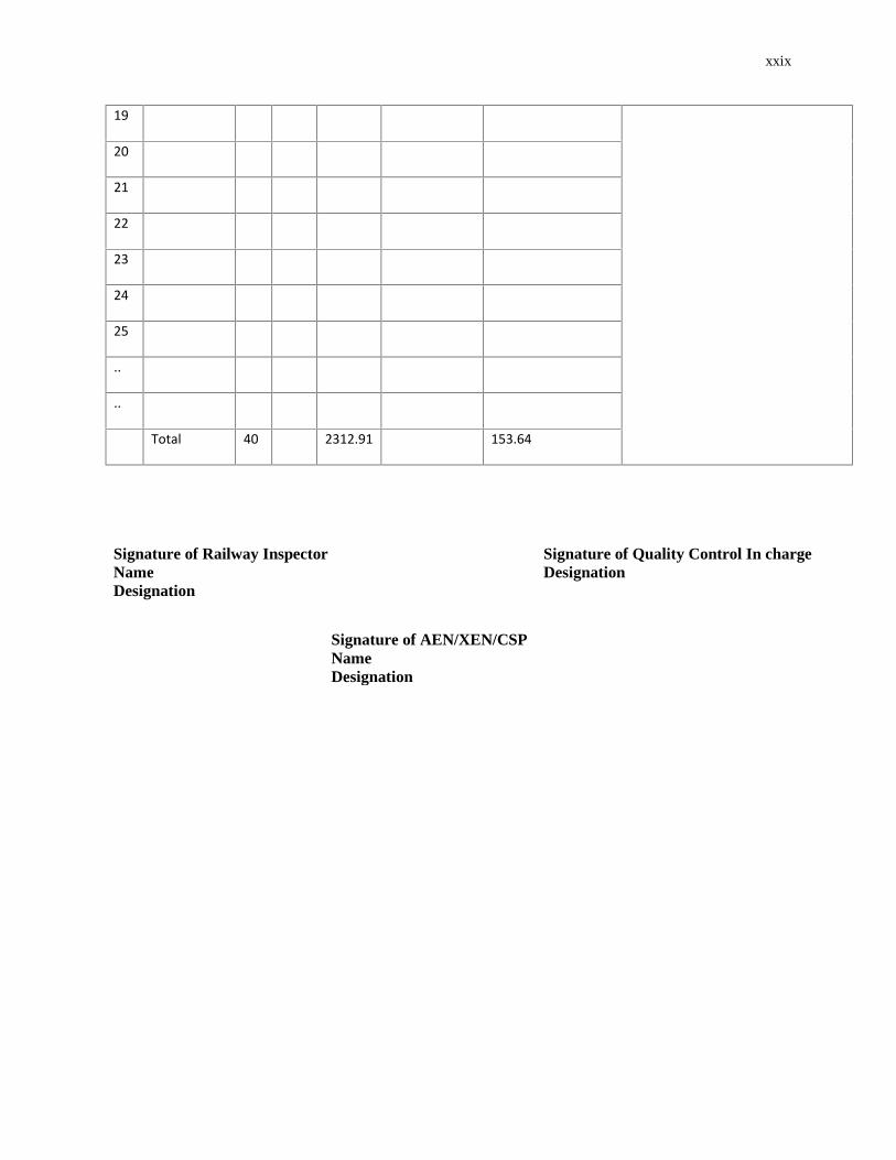
Total 40 2312.91 153.64
Signature of Railway InspectorNameDesignation
Signature of Quality Control In chargeDesignation
Signature of AEN/XEN/CSPNameDesignation