Embed Size (px)
Citation preview
Real-world uncertainties during a site assessment of vapourmigration into a residential house from soil and groundwater
Tom Parker1, Hannah White2*, Gareth Taylor3, Frank Evans3 & Matthew Pearce31 Argentum Fox Ltd, The Wilderness, Gold St, Walgrave, Northampton NN6 9QE, UK2 Atkins, The Axis, 10 Holliday St, Birmingham B1 1TF, UK3 National Grid Property, Warwick Technology Park, Gallows Hill, Warwick CV34 6DA, UK
T.P., 0000-0002-7464-1359; H.W., 0000-0002-5613-1937; G.T., 0000-0003-1425-6683*Correspondence: [email protected]
Abstract: Assessing the relationship between hydrocarbon groundwater concentrations and overlying vapour concentrations isfraught with uncertainties resulting from effects of moisture and biodegradation in the capillary fringe above the water table, thecombined effects of solubility and Raoult’s law associated with free phase hydrocarbon and, not least, the subsequent potentialvapour transport mechanisms. This paper reports on a UK site containing an uninhabited house adjacent to soil andgroundwater source zones. Hydrocarbon concentrations within shallow groundwater, soil, soil vapour and indoor air have beenmeasured over several sampling events. Potential for biodegradation has been assessed using biotraps. Recent publications andthis site’s data suggest that models are conservative and may overestimate potential indoor air concentrations. Attenuation fromthe subsurface into the house may be less than predicted if preferential pathways exist, but preferential pathways limit modellingapplicability. As always, a robust and full understanding of the conceptual model is critical. At this site, and most real-worldsites, this understanding is often prohibitively expensive to obtain. Notwithstanding this caveat, the results at this site suggestthat both modelling algorithms and source-separation distance approaches are valid screening tools in the UK provided that arobust understanding of the conceptual model is developed.
Received 25 November 2016; revised 30 March 2017; accepted 5 April 2017
Assessment of potential vapour migration into UK houses fromsubsurface contamination has historically relied upon US modelssuch as that of Johnson & Ettinger (1991) with modifications toaccount for suspended timber floors typical of older UK housingstock, such as those in the study by Ferguson et al. (1998). Thesealgorithms have been noted by Environment Agency (2009) andProvoost et al. (2009) to have relatively high uncertainty owing topoorly understood spatial and temporal variability in subsurfaceconcentrations, and at real sites there is an ambition to verify themby field measurements. Although verification work on vapourintrusion has been done under the auspices of the UK’sContaminated Land regulatory regime (Defra 2012), much of thiswork remains unpublished. A lack of published field datadocumenting spatial–temporal variability in soil vapour concentra-tions at sites with timber floors is a data gap that this paper seeks tobegin to address, by comparing theoretical vapour intrusionestimations with measurements from an older residential propertywith both suspended and solid floors, where petroleum or coal-tarderived contamination is present in the adjacent subsurface.
Conceptual site model
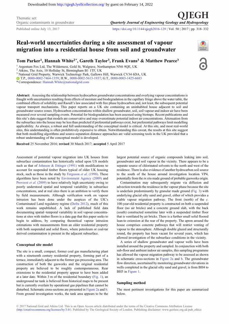
The site is a small, compact, former coal gas manufacturing plantwith a nineteenth century residential property, forming part of aterrace, immediately adjacent to the former gas processing area. Theconstruction of both the gasworks and the original residentialproperty are believed to be roughly contemporaneous. Rearextensions to the residential property appear to have been addedat a later date. Within 3 m of the residential boundary (Fig. 1), anunderground tar tank is believed from historical maps to be presentbut is currently overlain by operational gas pipelines that cannot bedisturbed. Schematic cross-sections are presented in Figure 2a and b.From ground investigation works, the tank area appears to be the
largest potential source of organic compounds leaking into soil,groundwater and soil vapour in the vicinity. There appears to be aseparate source of chlorinated solvents to the north and west of theresidence. There is also evidence of another hydrocarbon soil sourceto the south of the house around investigation location VP4,potentially from the in situmade ground of probable gasworks origin.
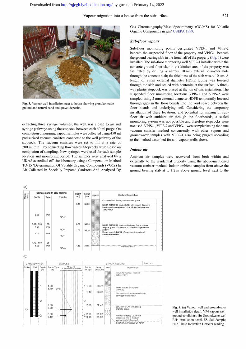
Contamination may subsequently migrate via diffusion andadvection towards the residence in the vapour phase because the siteis underlain predominantly by granular made ground (Fig. 3) withunderlying glacial silty sand and gravel, either of which provides aviable vapour migration pathway. The front (north) of the c.100-year-old residential property is constructed on both a suspendedfloor (no air bricks) and a concrete ground slab, with the back(south) constructed sometime later with a suspended timber floorthat is ventilated by air bricks. There is a further small solid flooredlean-to extension at the rear of the property. The apron around thehouse comprises concrete pathways that will restrict venting ofvapour to the atmosphere. Although double glazed and structurallysound, the property has been vacant for several years, which hasallowed investigation of the subsurface conditions in the vicinity.
A series of shallow groundwater and vapour wells have beeninstalled around the property and sampled. In conjunction with bothsub-floor and ambient indoor air samples, this sampling programmehas allowed the vapour migration pathway to be assessed as shownin schematic cross-sections in Figure 2a and b. The groundwaterflow direction, ascertained by monitoring groundwater elevations inwells completed in the glacial silty sand and gravel, is from BH4 toBH5 in Figure 1.
Sampling method
The most pertinent investigations for this paper are summarizedbelow.
© 2017 National Grid and Atkins Ltd. This is an Open Access article distributed under the terms of the Creative Commons Attribution License(http://creativecommons.org/licenses/by/3.0/). Published by The Geological Society of London. Publishing disclaimer: www.geolsoc.org.uk/pub_ethics
Thematic set:Organic contaminants in groundwater Quarterly Journal of Engineering Geology and Hydrogeology
Published online July 13, 2017 https://doi.org/10.1144/qjegh2016-129 | Vol. 50 | 2017 | pp. 318–332
by guest on February 14, 2022http://qjegh.lyellcollection.org/Downloaded from
Soil
Borehole soil samples were recovered from the shallow madeground and from the underlying natural strata, if encountered, fromfive locations close to the house up to a maximum depth of 1.5 mbelow ground level (mbgl).
Groundwater
Wells were constructed with a high-density polyethylene (HDPE)casing, screened at the water table, with a filter sand pack around thescreened interval and a bentonite seal to surface. An examplegroundwater well construction is shown in Figure 4b. Groundwatersampling was undertaken from the five groundwater wells shown inFigure 1 on four occasions over 18 months. Depth to groundwater isshown in Table 1. As an indication of groundwater contamination,well BH5, completed in the sandy gravel c. 15 m directly downgroundwater flow gradient from the presumed tar tank, contained a1 mm thickness of light non-aqueous phase liquid (LNAPL) on oneoccasion at a depth of c. 1.9 mbgl.
The groundwater sampling was undertaken using a low-flowmethod comprising the use of a peristaltic pump and flow cell. Thesample depth was chosen so as to be within the installed responsezone, with the flow rate of the pump set such that the well was notde-watered during sampling and did not exceed 1 l min−1. Prior tosampling, the well was purged through the flow cell while recording
physicochemical parameters. Readings were recorded every minutefor the first 5 min and every 5 min thereafter and continued for atleast 25 min and until all parameters had stabilized to within 10%over at least two monitoring periods (i.e. 10 min). On completion ofpurging, the flow cell was disconnected and samples were decanteddirectly from the tubing into laboratory-supplied sterile glass jarsand vials suitable for the analysis to be undertaken. Vials were filledso as to ensure no headspace remained. The samples weretransported under chain of custody protocols and analysed forvolatile organic compounds (VOC) in waters by headspace gaschromatography mass spectrometry at a UK Accreditation Service(UKAS) accredited laboratory.
Soil vapour
During the soils investigation, vapour monitoring wells VP1–VP5were excavated by hand to a depth of c. 1 mbgl close to the houseand were installed with a narrow diameter (2 mm external diameter)HDPE vapour monitoring tube from c. 0.9 mbgl to surface to allowsubsequent collection of soil vapour samples. The wells werecompleted with coarse sand in the response zone (typically0.9 – 1.0 mbgl to provide an indication of vapour concentrationsin the unsaturated zone pathway) and sealed above and below theresponse zone with bentonite. A three-way plastic stopcock wasinstalled at the top of each installation and the well was closed to air.An indication of ground conditions in which vapour wells were
Fig. 1. Site plan, investigation and cross-section locations.
319Vapour migration into a house from the subsurface
by guest on February 14, 2022http://qjegh.lyellcollection.org/Downloaded from
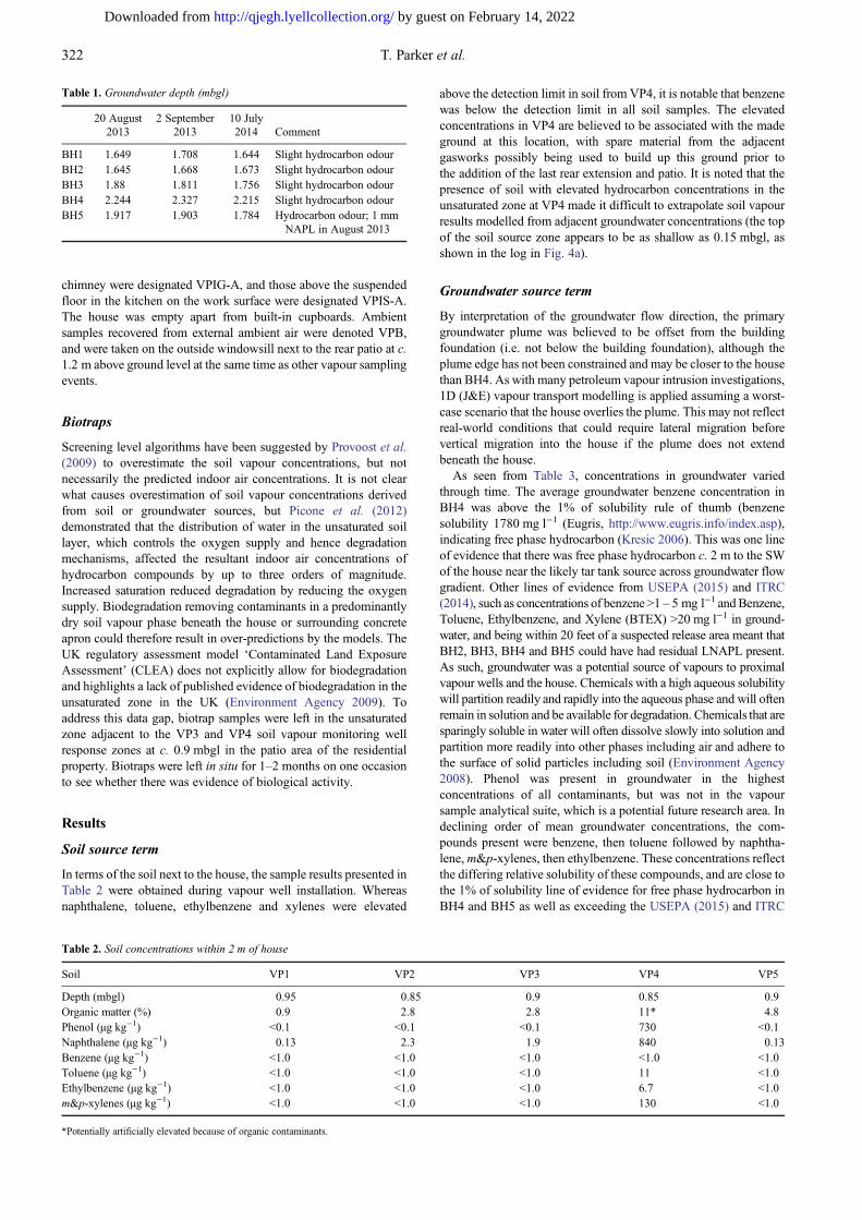
installed is shown in Figure 4a. Soil vapour from VP1–VP5 wassampled on five occasions over a period of 18 months (generallyconcurrent with groundwater sampling). Prior to sampling, theexternal soil vapour wells were purged. Purging was carried out
using a disposable 60 ml plastic syringe attached to the three-waystopcock using a screw fitting. The stopcock was opened so as tolink the tubing with the syringe and prevent ingress of ambient air tothe well. A total of 180 ml of air was purged from the system by
Fig. 2. (a) Schematic cross-section A–A′ (north–south). (b) Schematic cross-section B–B′ (west–east).
320 T. Parker et al.
by guest on February 14, 2022http://qjegh.lyellcollection.org/Downloaded from
extracting three syringe volumes; the well was closed to air andsyringe pathways using the stopcock between each 60 ml purge. Oncompletion of purging, vapour samples were collected using 450 mlpressurized vacuum canisters connected to the well pathway of thestopcock. The vacuum canisters were set to fill at a rate of200 ml min−1 by connecting flow valves. Stopcocks were closed oncompletion of sampling. New syringes were used for each samplelocation and monitoring period. The samples were analysed by aUKAS accredited off-site laboratory using a Compendium MethodTO-15 ‘Determination Of Volatile Organic Compounds (VOCs) InAir Collected In Specially-Prepared Canisters And Analyzed By
Gas Chromatography/Mass Spectrometry (GC/MS) for VolatileOrganic Compounds in gas’ USEPA 1999.
Sub-floor vapour
Sub-floor monitoring points designated VPIS-1 and VPIS-2beneath the suspended floor of the property and VPIG-1 beneaththe ground bearing slab in the front half of the property (Fig. 1) wereinstalled. The sub-floor monitoring well VPIG-1 installed within theconcrete ground floor slab in the kitchen area of the property wasfacilitated by drilling a narrow 10 mm external diameter holethrough the concrete slab; the thickness of the slab was c. 10 cm. Alength of 2 mm external diameter HDPE tubing was loweredthrough the slab and sealed with bentonite at the surface. A three-way plastic stopcock was placed at the top of this installation. Thesuspended floor monitoring locations VPIS-1 and VPIS-2 weresampled using 2 mm external diameter HDPE temporarily loweredthrough gaps in the floor boards into the void space between thefloor boards and underlying soil. Considering the temporaryinstallation of these locations, and potential for mixing of sub-floor air with ambient air through the floorboards, a sealedmonitoring system was not possible and therefore stopcocks werenot used. VPIS-1, VPIS-2 and VPIG-1 were sampled using the samevacuum canister method concurrently with other vapour andgroundwater samples with VPIG-1 also being purged accordingto the method described for soil vapour wells above.
Indoor air
Ambient air samples were recovered from both within andexternally to the residential property using the above-mentionedvacuum canister method. Indoor ambient samples from above theground bearing slab at c. 1.2 m above ground level next to the
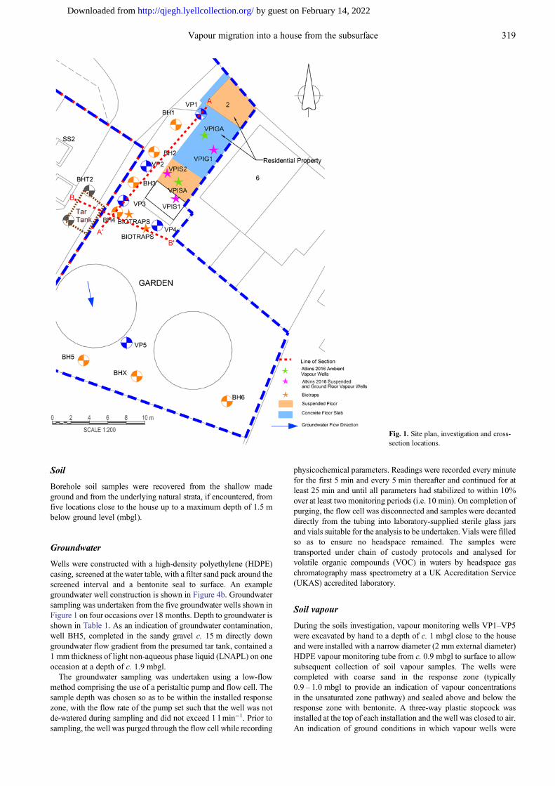
Fig. 3. Vapour well installation next to house showing granular madeground and natural sand and gravel deposits.
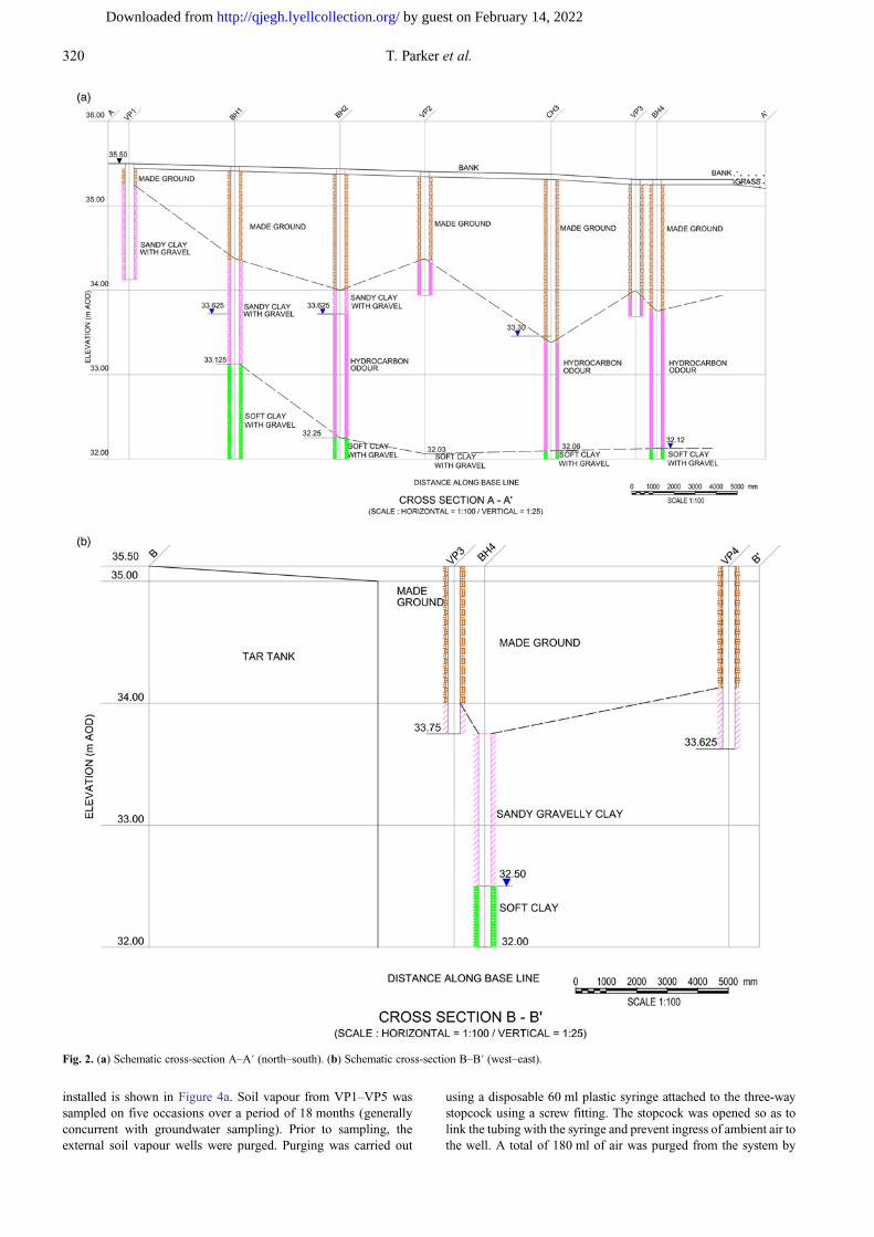
Fig. 4. (a) Vapour well and groundwaterwell installation detail. VP4 vapour wellground conditions. (b) Groundwater wellBH4 installation detail. ES, Soil Sample;PID, Photo Ionization Detector reading.
321Vapour migration into a house from the subsurface
by guest on February 14, 2022http://qjegh.lyellcollection.org/Downloaded from
chimney were designated VPIG-A, and those above the suspendedfloor in the kitchen on the work surface were designated VPIS-A.The house was empty apart from built-in cupboards. Ambientsamples recovered from external ambient air were denoted VPB,and were taken on the outside windowsill next to the rear patio at c.1.2 m above ground level at the same time as other vapour samplingevents.
Biotraps
Screening level algorithms have been suggested by Provoost et al.(2009) to overestimate the soil vapour concentrations, but notnecessarily the predicted indoor air concentrations. It is not clearwhat causes overestimation of soil vapour concentrations derivedfrom soil or groundwater sources, but Picone et al. (2012)demonstrated that the distribution of water in the unsaturated soillayer, which controls the oxygen supply and hence degradationmechanisms, affected the resultant indoor air concentrations ofhydrocarbon compounds by up to three orders of magnitude.Increased saturation reduced degradation by reducing the oxygensupply. Biodegradation removing contaminants in a predominantlydry soil vapour phase beneath the house or surrounding concreteapron could therefore result in over-predictions by the models. TheUK regulatory assessment model ‘Contaminated Land ExposureAssessment’ (CLEA) does not explicitly allow for biodegradationand highlights a lack of published evidence of biodegradation in theunsaturated zone in the UK (Environment Agency 2009). Toaddress this data gap, biotrap samples were left in the unsaturatedzone adjacent to the VP3 and VP4 soil vapour monitoring wellresponse zones at c. 0.9 mbgl in the patio area of the residentialproperty. Biotraps were left in situ for 1–2 months on one occasionto see whether there was evidence of biological activity.
Results
Soil source term
In terms of the soil next to the house, the sample results presented inTable 2 were obtained during vapour well installation. Whereasnaphthalene, toluene, ethylbenzene and xylenes were elevated
above the detection limit in soil from VP4, it is notable that benzenewas below the detection limit in all soil samples. The elevatedconcentrations in VP4 are believed to be associated with the madeground at this location, with spare material from the adjacentgasworks possibly being used to build up this ground prior tothe addition of the last rear extension and patio. It is noted that thepresence of soil with elevated hydrocarbon concentrations in theunsaturated zone at VP4 made it difficult to extrapolate soil vapourresults modelled from adjacent groundwater concentrations (the topof the soil source zone appears to be as shallow as 0.15 mbgl, asshown in the log in Fig. 4a).
Groundwater source term
By interpretation of the groundwater flow direction, the primarygroundwater plume was believed to be offset from the buildingfoundation (i.e. not below the building foundation), although theplume edge has not been constrained and may be closer to the housethan BH4. As with many petroleum vapour intrusion investigations,1D (J&E) vapour transport modelling is applied assuming a worst-case scenario that the house overlies the plume. This may not reflectreal-world conditions that could require lateral migration beforevertical migration into the house if the plume does not extendbeneath the house.
As seen from Table 3, concentrations in groundwater variedthrough time. The average groundwater benzene concentration inBH4 was above the 1% of solubility rule of thumb (benzenesolubility 1780 mg l−1 (Eugris, http://www.eugris.info/index.asp),indicating free phase hydrocarbon (Kresic 2006). This was one lineof evidence that there was free phase hydrocarbon c. 2 m to the SWof the house near the likely tar tank source across groundwater flowgradient. Other lines of evidence from USEPA (2015) and ITRC(2014), such as concentrations of benzene >1 – 5 mg l−1 andBenzene,Toluene, Ethylbenzene, and Xylene (BTEX) >20 mg l−1 in ground-water, and being within 20 feet of a suspected release area meant thatBH2, BH3, BH4 and BH5 could have had residual LNAPL present.As such, groundwater was a potential source of vapours to proximalvapour wells and the house. Chemicals with a high aqueous solubilitywill partition readily and rapidly into the aqueous phase and will oftenremain in solution and be available for degradation. Chemicals that aresparingly soluble in water will often dissolve slowly into solution andpartition more readily into other phases including air and adhere tothe surface of solid particles including soil (Environment Agency2008). Phenol was present in groundwater in the highestconcentrations of all contaminants, but was not in the vapoursample analytical suite, which is a potential future research area. Indeclining order of mean groundwater concentrations, the com-pounds present were benzene, then toluene followed by naphtha-lene,m&p-xylenes, then ethylbenzene. These concentrations reflectthe differing relative solubility of these compounds, and are close tothe 1% of solubility line of evidence for free phase hydrocarbon inBH4 and BH5 as well as exceeding the USEPA (2015) and ITRC
Table 2. Soil concentrations within 2 m of house
Soil VP1 VP2 VP3 VP4 VP5
Depth (mbgl) 0.95 0.85 0.9 0.85 0.9Organic matter (%) 0.9 2.8 2.8 11* 4.8Phenol (µg kg−1) <0.1 <0.1 <0.1 730 <0.1Naphthalene (µg kg−1) 0.13 2.3 1.9 840 0.13Benzene (µg kg−1) <1.0 <1.0 <1.0 <1.0 <1.0Toluene (µg kg−1) <1.0 <1.0 <1.0 11 <1.0Ethylbenzene (µg kg−1) <1.0 <1.0 <1.0 6.7 <1.0m&p-xylenes (µg kg−1) <1.0 <1.0 <1.0 130 <1.0
*Potentially artificially elevated because of organic contaminants.
Table 1. Groundwater depth (mbgl)
20 August2013
2 September2013
10 July2014 Comment
BH1 1.649 1.708 1.644 Slight hydrocarbon odourBH2 1.645 1.668 1.673 Slight hydrocarbon odourBH3 1.88 1.811 1.756 Slight hydrocarbon odourBH4 2.244 2.327 2.215 Slight hydrocarbon odourBH5 1.917 1.903 1.784 Hydrocarbon odour; 1 mm
NAPL in August 2013
322 T. Parker et al.
by guest on February 14, 2022http://qjegh.lyellcollection.org/Downloaded from
(2014) indicative limits. Concentrations of these hydrocarbons inthe other wells were two to >10 times lower.
The average depth to groundwater in the area over the 18 monthmonitoring period was between 1.65 and 2.04 mbgl, indicating thethickness of the unsaturated zone. BH1 is up-hydraulic (ground-water flow) gradient from the suspected tar tank source and this wasgenerally reflected in the contaminant concentrations being at orbelow the detection limit. Naphthalene concentrations in ground-water were just above detection limit at BH1, suggesting somelimited background contamination in this area. Wells BH2 and BH3were also up-hydraulic gradient of the tar tank position indicated onhistorical plans and confirmed there were other potential gasworkssources of contamination, likely to be associated with the gasworksretort house based on old plans. BH4 is across groundwater flow
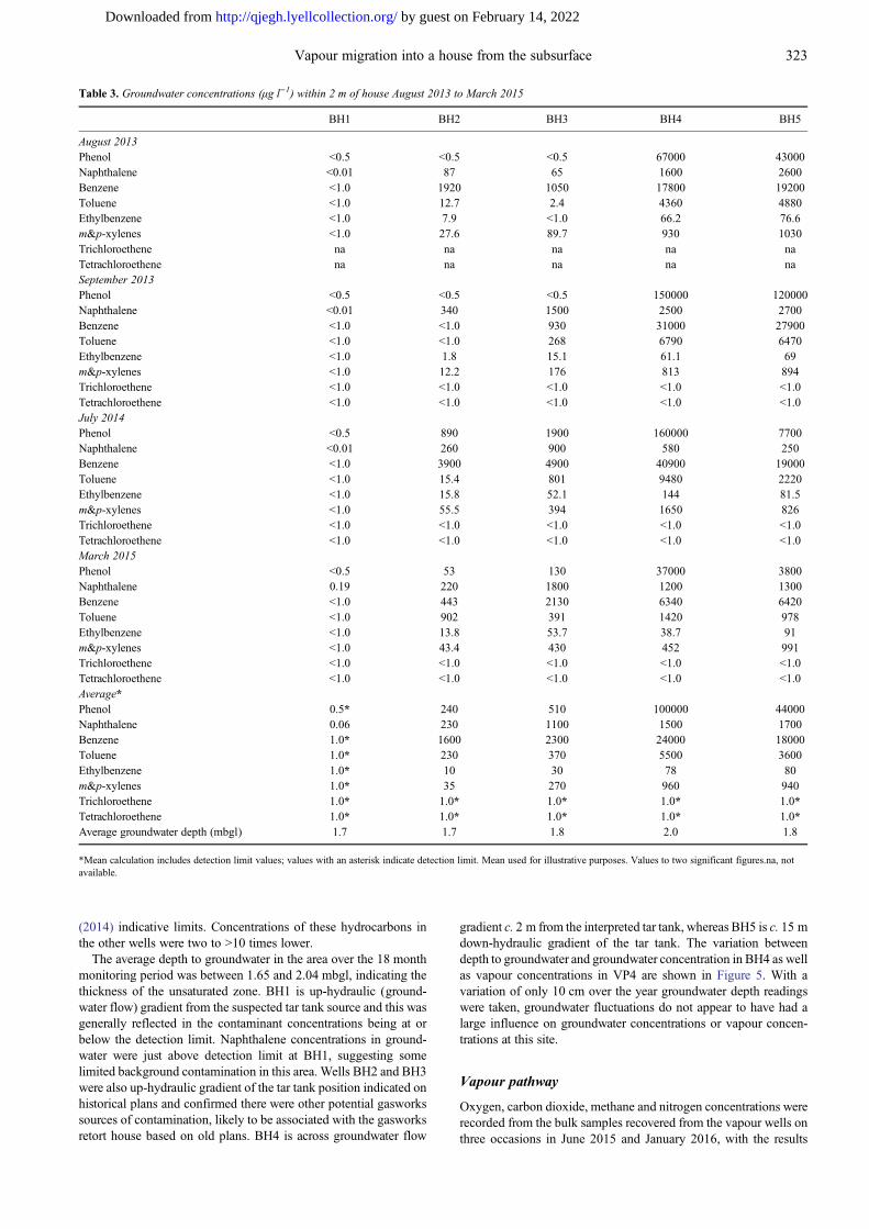
gradient c. 2 m from the interpreted tar tank, whereas BH5 is c. 15 mdown-hydraulic gradient of the tar tank. The variation betweendepth to groundwater and groundwater concentration in BH4 as wellas vapour concentrations in VP4 are shown in Figure 5. With avariation of only 10 cm over the year groundwater depth readingswere taken, groundwater fluctuations do not appear to have had alarge influence on groundwater concentrations or vapour concen-trations at this site.
Vapour pathway
Oxygen, carbon dioxide, methane and nitrogen concentrations wererecorded from the bulk samples recovered from the vapour wells onthree occasions in June 2015 and January 2016, with the results
Table 3. Groundwater concentrations (µg l−1) within 2 m of house August 2013 to March 2015
BH1 BH2 BH3 BH4 BH5
August 2013Phenol <0.5 <0.5 <0.5 67000 43000Naphthalene <0.01 87 65 1600 2600Benzene <1.0 1920 1050 17800 19200Toluene <1.0 12.7 2.4 4360 4880Ethylbenzene <1.0 7.9 <1.0 66.2 76.6m&p-xylenes <1.0 27.6 89.7 930 1030Trichloroethene na na na na naTetrachloroethene na na na na naSeptember 2013Phenol <0.5 <0.5 <0.5 150000 120000Naphthalene <0.01 340 1500 2500 2700Benzene <1.0 <1.0 930 31000 27900Toluene <1.0 <1.0 268 6790 6470Ethylbenzene <1.0 1.8 15.1 61.1 69m&p-xylenes <1.0 12.2 176 813 894Trichloroethene <1.0 <1.0 <1.0 <1.0 <1.0Tetrachloroethene <1.0 <1.0 <1.0 <1.0 <1.0July 2014Phenol <0.5 890 1900 160000 7700Naphthalene <0.01 260 900 580 250Benzene <1.0 3900 4900 40900 19000Toluene <1.0 15.4 801 9480 2220Ethylbenzene <1.0 15.8 52.1 144 81.5m&p-xylenes <1.0 55.5 394 1650 826Trichloroethene <1.0 <1.0 <1.0 <1.0 <1.0Tetrachloroethene <1.0 <1.0 <1.0 <1.0 <1.0March 2015Phenol <0.5 53 130 37000 3800Naphthalene 0.19 220 1800 1200 1300Benzene <1.0 443 2130 6340 6420Toluene <1.0 902 391 1420 978Ethylbenzene <1.0 13.8 53.7 38.7 91m&p-xylenes <1.0 43.4 430 452 991Trichloroethene <1.0 <1.0 <1.0 <1.0 <1.0Tetrachloroethene <1.0 <1.0 <1.0 <1.0 <1.0Average*Phenol 0.5* 240 510 100000 44000Naphthalene 0.06 230 1100 1500 1700Benzene 1.0* 1600 2300 24000 18000Toluene 1.0* 230 370 5500 3600Ethylbenzene 1.0* 10 30 78 80m&p-xylenes 1.0* 35 270 960 940Trichloroethene 1.0* 1.0* 1.0* 1.0* 1.0*Tetrachloroethene 1.0* 1.0* 1.0* 1.0* 1.0*Average groundwater depth (mbgl) 1.7 1.7 1.8 2.0 1.8
*Mean calculation includes detection limit values; values with an asterisk indicate detection limit. Mean used for illustrative purposes. Values to two significant figures.na, notavailable.
323Vapour migration into a house from the subsurface
by guest on February 14, 2022http://qjegh.lyellcollection.org/Downloaded from
shown in Table 4. These indicate that aerobic conditions existed atall locations at all times. There was evidence of oxygenconsumption at wells VP3, VP4 and VP5, and occasional oxygenconsumption beneath the suspended floor VPIS-1 in June 2015. Allvapour samples had slightly more carbon dioxide than ambientsamples, suggesting that short-circuiting to atmosphere was notoccurring.
There were multiple detections of hydrocarbon vapour in VP1,which is up-hydraulic gradient from the other wells and sources.Given naphthalene was the only contaminant detected in soil andgroundwater at this location, the presence of other volatilecomponents in the vapour sample(s) was evidence of a sourceother than the tar tank. No proximal soil or groundwater sourceshave been identified nearby for vapour in VP1 although thehistorical gasworks retort house was c. 15 m away. The soil vapourresults are shown in Tables 5 – 7.
The distribution of contaminants in the vapour phase moreclosely correlated with groundwater as opposed to soil concentra-tions, with toluene having the highest of the contaminant vapourconcentrations. However, a further distinction could be made inthat unless the vapour monitoring points are within a few metres of
a proven groundwater source, the correlation between soil vapourand groundwater was also limited. McAlary et al. (2011)suggested that using a soil concentration as starting point,instead of groundwater concentration, is generally not recom-mended for assessing subsurface vapour intrusion to indoor airbecause there are no published studies that clearly show a directrelationship between measured soil concentrations and measuredsoil vapour concentrations. Apart from the soil concentrations atVP4, soils at this site provided a poor indication of vapourconcentrations. Lahvis et al. (2013) went further and suggestedthat neither soil nor groundwater concentrations correlate well withsoil vapour concentrations at petroleum vapour intrusion sites.Although the presence or absence of compounds in the vapourphase correlated roughly with the presence or absence ingroundwater for BTEX compounds, the Lahvis et al. (2013)supposition was also generally supported at this site. For example,the vapour phase benzene concentrations were lower than tolueneconcentrations in all vapour wells in all sampling rounds wherethere were groundwater data (except VP3 in March 2015), despitebenzene exceeding toluene concentrations within groundwater inall groundwater wells in all sampling rounds (except BH2 in
Table 4. Bulk gas readings during purging prior to vapour sampling
External soil vapour Sub-floor vapour Indoor air samplesBackground ambient
VP1 VP2 VP3 VP4 VP5 VPIG-1 VPIS-1 VPIS-2 VP1G-A VP1S-A VPA
22 June 2015Carbon dioxide 0.63 0.15 2.08 1.53 6.57 0.08 1.42 <0.05 na na <0.05Carbon monoxide <0.05 <0.05 <0.05 <0.05 <0.05 <0.05 <0.05 <0.05 na na <0.05Methane <0.05 <0.05 <0.05 <0.05 <0.05 <0.05 <0.05 <0.05 na na <0.05Nitrogen 79.8 79.2 80.2 79.7 87 79.4 81 79.3 na na 79.1Oxygen 19.5 20.7 17.7 18.8 6.4 20.5 17.6 20.6 na na 20.927 January 2016Carbon dioxide 0.32 0.43 0.38 0.85 1.09 0.11 0.08 0.09 0.08 0.1 0.06Carbon monoxide <0.05 <0.05 <0.05 <0.05 <0.05 <0.05 <0.05 <0.05 <0.05 <0.05 <0.05Methane <0.05 <0.05 <0.05 <0.05 <0.05 <0.05 <0.05 <0.05 <0.05 <0.05 <0.05Nitrogen 78.9 79.6 78.9 79.3 84.7 79.1 79.1 79.1 79.1 79.1 79.1Oxygen 20.8 20 20.8 19.9 14.2 20.8 20.8 20.9 20.8 20.8 20.828 January 2016Carbon dioxide 0.36 0.26 0.66 0.93 0.89 0.16 0.1 0.08 0.09 0.12 <0.05Carbon monoxide <0.05 <0.05 <0.05 <0.05 <0.05 <0.05 <0.05 <0.05 <0.05 <0.05 <0.05Methane <0.05 <0.05 <0.05 <0.05 <0.05 <0.05 <0.05 <0.05 <0.05 <0.05 <0.05Nitrogen 78.9 78.8 79 79.1 81.3 79 79.1 79.1 79.2 79.1 79.1Oxygen 20.7 20.9 20.4 20 17.9 20.8 20.8 20.8 20.7 20.8 20.8
na, not available.
Fig. 5. Groundwater and vapour variationover time in BH4 and VP4.
324 T. Parker et al.
by guest on February 14, 2022http://qjegh.lyellcollection.org/Downloaded from
March 2015). The Henry’s Law constants for these twocontaminants are relatively similar (benzene 557 Pa m3 mol−1
(25°C), toluene 660 Pa m3 mol−1 (25°C); Environment Agency2008; Mackay et al. 1979) so the fact that dissolved benzeneconcentrations were over five times greater than those of tolueneshould have meant that vapour concentrations were similarlyelevated. In addition, groundwater elevation fluctuation means thata smear zone can be created, where the higher vapour pressure ofbenzene might have been expected to increase the benzene vapourconcentration relative to toluene. This may not be a large factor atthis site because the smear zone is likely to be limited as a resultof small groundwater fluctuations over the monitoring period(Table 1). The interpretation for benzene concentrations in vapourbeing consistently lower than the toluene concentrations in allvapour wells when toluene was detected was that either (1) therewas another localized unsaturated zone source of toluene, but thiswas not seen in soil concentrations, or (2) the benzene was beingrapidly degraded in the unsaturated zone. Degradation was further
supported by the consistent absence of benzene in the vapourphase both up groundwater flow gradient in VP1 (excluding June2015) and c. 15 m down groundwater gradient in VP5.
The presence of trichloroethene and tetrachloroethene in soilvapour was unexpected because they are not typical gasworkscontaminants. The most likely source was the adjacent formergasworks where solvents and degreasers may have been used. Theabsence of these compounds in groundwater suggested anunsaturated zone vapour source, but further investigation of thepotential source was constrained by the site size and accessconstraints.
Naphthalene was never detected beneath the house nor in indoorair, suggesting that it was attenuated in the vapour pathway or wastoo strongly sorbed to the soil sediments to volatilize. Hayes et al.(2006) suggested that polyethylene tubing can be subject toabsorption of chemicals of potential concern such as naphthalene,resulting in negative bias in results, which is another potentialreason why naphthalene was not detected in the vapour phase.
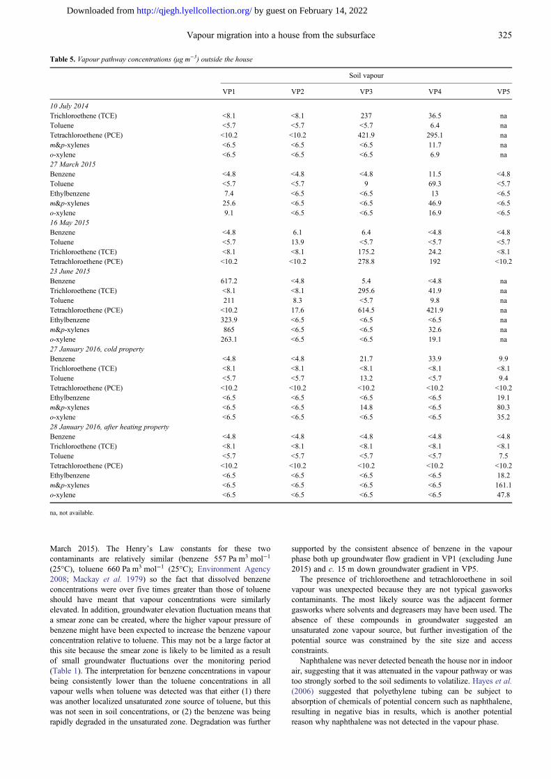
Table 5. Vapour pathway concentrations (µg m−3) outside the house
Soil vapour
VP1 VP2 VP3 VP4 VP5
10 July 2014Trichloroethene (TCE) <8.1 <8.1 237 36.5 naToluene <5.7 <5.7 <5.7 6.4 naTetrachloroethene (PCE) <10.2 <10.2 421.9 295.1 nam&p-xylenes <6.5 <6.5 <6.5 11.7 nao-xylene <6.5 <6.5 <6.5 6.9 na27 March 2015Benzene <4.8 <4.8 <4.8 11.5 <4.8Toluene <5.7 <5.7 9 69.3 <5.7Ethylbenzene 7.4 <6.5 <6.5 13 <6.5m&p-xylenes 25.6 <6.5 <6.5 46.9 <6.5o-xylene 9.1 <6.5 <6.5 16.9 <6.516 May 2015Benzene <4.8 6.1 6.4 <4.8 <4.8Toluene <5.7 13.9 <5.7 <5.7 <5.7Trichloroethene (TCE) <8.1 <8.1 175.2 24.2 <8.1Tetrachloroethene (PCE) <10.2 <10.2 278.8 192 <10.223 June 2015Benzene 617.2 <4.8 5.4 <4.8 naTrichloroethene (TCE) <8.1 <8.1 295.6 41.9 naToluene 211 8.3 <5.7 9.8 naTetrachloroethene (PCE) <10.2 17.6 614.5 421.9 naEthylbenzene 323.9 <6.5 <6.5 <6.5 nam&p-xylenes 865 <6.5 <6.5 32.6 nao-xylene 263.1 <6.5 <6.5 19.1 na27 January 2016, cold propertyBenzene <4.8 <4.8 21.7 33.9 9.9Trichloroethene (TCE) <8.1 <8.1 <8.1 <8.1 <8.1Toluene <5.7 <5.7 13.2 <5.7 9.4Tetrachloroethene (PCE) <10.2 <10.2 <10.2 <10.2 <10.2Ethylbenzene <6.5 <6.5 <6.5 <6.5 19.1m&p-xylenes <6.5 <6.5 14.8 <6.5 80.3o-xylene <6.5 <6.5 <6.5 <6.5 35.228 January 2016, after heating propertyBenzene <4.8 <4.8 <4.8 <4.8 <4.8Trichloroethene (TCE) <8.1 <8.1 <8.1 <8.1 <8.1Toluene <5.7 <5.7 <5.7 <5.7 7.5Tetrachloroethene (PCE) <10.2 <10.2 <10.2 <10.2 <10.2Ethylbenzene <6.5 <6.5 <6.5 <6.5 18.2m&p-xylenes <6.5 <6.5 <6.5 <6.5 161.1o-xylene <6.5 <6.5 <6.5 <6.5 47.8
na, not available.
325Vapour migration into a house from the subsurface
by guest on February 14, 2022http://qjegh.lyellcollection.org/Downloaded from

Although Tables 5 – 8 provide an overview of average contam-inant distribution, they do not show the variation over time. Figure 5shows the variation of selected contaminant concentrations in thesoil vapour and groundwater for BH4 and VP4 in conjunction withdepth to groundwater in BH4 (secondary axis). These wells are c.3 m apart and contained the highest contaminant groundwater andvapour concentrations. The vapour in VP4 could have been derivedfrom either in situ soil made ground contaminants or groundwatercontamination emanating from the groundwater plume. Thepresence of chlorinated solvents in soil vapour but not ingroundwater in VP2, VP3 and VP4 suggested there was anadditional unsaturated zone soil vapour source that could not beinvestigated at this site owing to size and access constraints.
The continuous lines in Figure 5 show that vapour concentrationsvaried dramatically between monitoring rounds, from orders ofmagnitude above to below the detection limit. The dashed linesshow that groundwater contaminant concentrations also changedwith time, but in a less pronounced manner. Even though thedistribution of BTEX vapour appeared to be related to the presence
of groundwater contamination, the temporal trends in the two phasesdid not correlate closely. This suggested that the processes takingplace in the vapour phase caused greater variability in vapourconcentrations than relatively minor variations observed in thegroundwater phase concentrations. One possibility that has not beeninvestigated in this paper is whether contaminant mass transfer tothe unsaturated zone has taken place owing to groundwaterfluctuations (McAlary et al. 2011), but there is likely to be alimited smear zone at this site owing to small groundwater elevationfluctuations (Table 1).
Recent research (Guo et al. 2015) has identified preferentialpathways (e.g. sewers, land drains and other underground piping) ascritical factors in vapour intrusion assessments. Such pathways aredifficult to identify through conventional sampling. Controlledpressure method (CPM) testing can be used to identify alternativevapour intrusion pathways that may go undetected using conventionalsampling methods. At the Guo et al. (2015) study site, measuredemission rates of volatile organic compounds were two orders ofmagnitude greater than screening model estimates owing to
Table 6. Vapour pathway concentrations (µg m−3) beneath the house
Sub-slab
VPIS-1, suspended floor VPIS-2, suspended floor VPIG-1, solid floor
10 July 2014Trichloroethene (TCE) na na naToluene na na naTetrachloroethene (PCE) na na nam&p-xylenes na na nao-xylene na na na27 March 2015Benzene <4.8 8.6 6.1Toluene <5.7 7.5 6.8Ethylbenzene 6.9 <6.5 <6.5m&p-xylenes 26.5 <6.5 <6.5o-xylene 7.8 <6.5 <6.516 May 2015Benzene 6.7 5.4 8.3Trichloroethene (TCE) 13.4 <8.1 <8.1Tetrachloroethene (PCE) <10.2 <10.2 <10.223 June 2015Benzene <4.8 <4.8 <4.8Trichloroethene (TCE) <8.1 <8.1 <8.1Toluene <5.7 <5.7 <5.7Tetrachloroethene (PCE) <10.2 <10.2 <10.2Ethylbenzene <6.5 <6.5 <6.5m&p-xylenes <6.5 <6.5 <6.5o-xylene <6.5 <6.5 <6.527 January 2016, cold propertyBenzene 76 <4.8 <4.8Trichloroethene (TCE) <8.1 <8.1 <8.1Toluene <5.7 <5.7 <5.7Tetrachloroethene (PCE) <10.2 <10.2 <10.2Ethylbenzene 13 <6.5 <6.5m&p-xylenes 19.5 <6.5 <6.5o-xylene <6.5 <6.5 <6.528 January 2016, warm propertyBenzene <4.8 <4.8 <4.8Trichloroethene (TCE) <8.1 <8.1 <8.1Toluene <5.7 <5.7 <5.7Tetrachloroethene (PCE) <10.2 <10.2 <10.2Ethylbenzene <6.5 <6.5 <6.5m&p-xylenes <6.5 <6.5 <6.5o-xylene <6.5 <6.5 <6.5
na, not available.
326 T. Parker et al.
by guest on February 14, 2022http://qjegh.lyellcollection.org/Downloaded from
alternative pathways (sewers). CPM testing was beyond the scope ofthis investigation and inmanyother real-world assessments especiallywhen the houses are inhabited, but preferential pathway flow mayhave played an important role in vapour intrusion at this site.
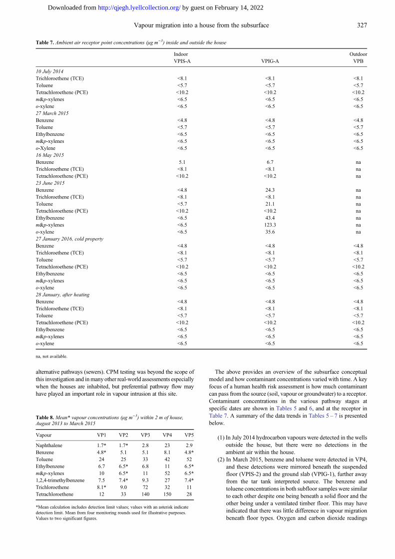
The above provides an overview of the subsurface conceptualmodel and how contaminant concentrations varied with time. A keyfocus of a human health risk assessment is how much contaminantcan pass from the source (soil, vapour or groundwater) to a receptor.Contaminant concentrations in the various pathway stages atspecific dates are shown in Tables 5 and 6, and at the receptor inTable 7. A summary of the data trends in Tables 5 – 7 is presentedbelow.
(1) In July 2014 hydrocarbon vapours were detected in the wellsoutside the house, but there were no detections in theambient air within the house.
(2) In March 2015, benzene and toluene were detected in VP4,and these detections were mirrored beneath the suspendedfloor (VPIS-2) and the ground slab (VPIG-1), further awayfrom the tar tank interpreted source. The benzene andtoluene concentrations in both subfloor samples were similarto each other despite one being beneath a solid floor and theother being under a ventilated timber floor. This may haveindicated that there was little difference in vapour migrationbeneath floor types. Oxygen and carbon dioxide readings
Table 8. Mean* vapour concentrations (µg m−3) within 2 m of house,August 2013 to March 2015
Vapour VP1 VP2 VP3 VP4 VP5
Naphthalene 1.7* 1.7* 2.8 23 2.9Benzene 4.8* 5.1 5.1 8.1 4.8*Toluene 24 25 33 42 52Ethylbenzene 6.7 6.5* 6.8 11 6.5*m&p-xylenes 10 6.5* 11 52 6.5*1,2,4-trimethylbenzene 7.5 7.4* 9.3 27 7.4*Trichloroethene 8.1* 9.0 72 32 11Tetrachloroethene 12 33 140 150 28
*Mean calculation includes detection limit values; values with an asterisk indicatedetection limit. Mean from four monitoring rounds used for illustrative purposes.Values to two significant figures.
Table 7. Ambient air receptor point concentrations (µg m−3) inside and outside the house
Indoor OutdoorVPIS-A VPIG-A VPB
10 July 2014Trichloroethene (TCE) <8.1 <8.1 <8.1Toluene <5.7 <5.7 <5.7Tetrachloroethene (PCE) <10.2 <10.2 <10.2m&p-xylenes <6.5 <6.5 <6.5o-xylene <6.5 <6.5 <6.527 March 2015Benzene <4.8 <4.8 <4.8Toluene <5.7 <5.7 <5.7Ethylbenzene <6.5 <6.5 <6.5m&p-xylenes <6.5 <6.5 <6.5o-Xylene <6.5 <6.5 <6.516 May 2015Benzene 5.1 6.7 naTrichloroethene (TCE) <8.1 <8.1 naTetrachloroethene (PCE) <10.2 <10.2 na23 June 2015Benzene <4.8 24.3 naTrichloroethene (TCE) <8.1 <8.1 naToluene <5.7 21.1 naTetrachloroethene (PCE) <10.2 <10.2 naEthylbenzene <6.5 43.4 nam&p-xylenes <6.5 123.3 nao-xylene <6.5 35.6 na27 January 2016, cold propertyBenzene <4.8 <4.8 <4.8Trichloroethene (TCE) <8.1 <8.1 <8.1Toluene <5.7 <5.7 <5.7Tetrachloroethene (PCE) <10.2 <10.2 <10.2Ethylbenzene <6.5 <6.5 <6.5m&p-xylenes <6.5 <6.5 <6.5o-xylene <6.5 <6.5 <6.528 January, after heatingBenzene <4.8 <4.8 <4.8Trichloroethene (TCE) <8.1 <8.1 <8.1Toluene <5.7 <5.7 <5.7Tetrachloroethene (PCE) <10.2 <10.2 <10.2Ethylbenzene <6.5 <6.5 <6.5m&p-xylenes <6.5 <6.5 <6.5o-xylene <6.5 <6.5 <6.5
na, not available.
327Vapour migration into a house from the subsurface
by guest on February 14, 2022http://qjegh.lyellcollection.org/Downloaded from
beneath the floor types would have been useful in assessingwhether there was a difference in aerobic conditions andbiological activity beneath each floor type (as was availablefor the June 2015 monitoring; Table 4). Ethylbenzene andxylenes were detected in VP1 at the northern end of thehouse, and this was mirrored beneath the ventilatedsuspended floor sample VPIS-1 (most southerly subfloorsample), rather than the beneath the ground slab VPIG-1,which is closer to VP1. There were no indoor air detectionsof the identified contaminants of concern in March 2015.
(3) In May 2015 benzene was detected in soil vapour, sub-slabvapour and indoor air at similar concentrations, just abovethe respective detection limits. This indicates that there wasno attenuation along the pathway or at the receptor, which isnot logical when considering literature-documented fate andtransport behaviour. The trace (detection limit × 5) benzenedetections in the May 2015 sampling should therefore beviewed with caution and may have been due to sampling oranalytical interference. Trichloroethene was detected in soilvapour outside the house and beneath the suspended floorbut not in indoor air, which was more logical because soilvapour should have become diluted as it entered indoor airowing to the regular air exchange rates expected in the house.
(4) Measured concentrations of BTEX compounds in soilvapour outside the house in VP1 were highest in June 2015.Vapour concentrations of BTEX compounds in VP1 werehigher in general than in VP4, which in other monitoringrounds contained the highest concentrations. However,none of the BTEX compounds were detected beneath thehouse in soil vapour. In June 2015, the highest indoor airconcentrations (BTEX only detected) were detected abovethe solid floor slab, but only in sample VPIG-A, closest toVP1. This suggested a short-circuiting pathway to thesource of soil vapour in VP1 (BTEX only detected), or acompromised adjacent sub-slab sample not showing theactive pathway. Sample VPIG-A was taken on a kitchenwork surface, with the wall behind forming a chimney.There were no obvious utilities or utility corridors enteringthe house at this location, so the chimney in conjunctionwith a permeable lateral feature beneath the house was thelikely potential preferential pathway. Tracer testing wouldneed to be done to test this hypothesis. Well VP4 is nearerthe better diluted wooden floor, which would encourageaerobic degradation and which may have explained the lackof vapour phase contaminants in the subfloor or ambientspace in these locations, even though soil vapour outside thehouse was elevated in June 2015. The ventilated sub-floorsample VPIS-1 showed evidence of localized oxygenconsumption in June 15, because, in contrast, the sub-slabsample VPIG-1 and the other suspended floor sampleVPIS-2 had oxygen concentrations similar to atmospheric,as seen in Table 4. In June 2015 tetrachloroethene wasdetected in VP2, VP3 and VP4 outside the house and
trichloroethene in VP3 and VP4, but neither compound wasdetected beneath the house nor in indoor or ambient air.
(5) In January 2016 two rounds of sampling were undertakenwith a gap of c. 19 h to allow the house to be heated, todetermine whether heating alone could cause vapours to besucked into the house via the stack effect. From Table 5,BTEX compounds were detected in VP3, VP4 and VP5 inthe first round of sampling. These perhaps representedsteady-state conditions, as there had been a long periodbefore these samples were taken when the well wasundisturbed. The concentrations beneath the suspendedfloor in VPIS-1 were the highest recorded with 76 µg m−3
benzene, 13 µg m−3 and 19.5 µg m−3 m&p-xylenes.Oxygen and carbon dioxide data indicated that the vapourbeneath the suspended floor and solid floor was similar toambient concentrations even after a long period with thehouse closed up. No hydrocarbon vapour was detected in thehouse or ambient air. During the second round of sampling,the following day, only toluene, ethylbenzene and xyleneswere detected in VP5, with xylenes detected in higherconcentrations than on the previous day. As noted in theprevious section, the groundwater well adjacent to VP5occasionally contains free phase hydrocarbon and theseconcentrations may have resulted from Raoult’s Lawpartitioning of the relative composition of the free phase(not known) in the vicinity. There were no detections belowthe house in sub-floor samples after heating the house. Afterheating the house, no hydrocarbon compounds weredetected in the house or ambient air. The effect of heatingthe house overnight did not appear to induce vapour flow tobeneath the house or into the house.
Ambient air in the house and to a lesser extent shallow vapourconcentrations beneath the house could have also varied in timedepending on wind, barometric pressure and temperature. Thesefactors are presented in Table 9 and further work could be done todetermine whether there are pressure gradients from inside tooutside the building or under-pressurization within the house duringindoor air sampling. Summer temperatures (average over 10°C)produced the highest soil vapour concentrations outside the house.Winter 2016 sampling produced the highest sub-floor concentra-tions under the suspended floor. There are insufficient data onatmospheric pressure, trend and wind speed to draw definitiveconclusions on these factors.
Biotrap samples
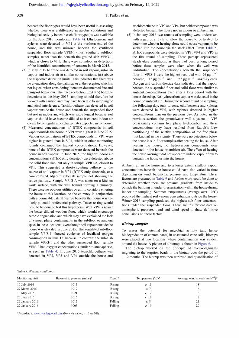
To assess the potential for microbial activity (and hencebiodegradation of contaminants) in unsaturated zone soils, biotrapswere placed at two locations where contamination was evidentaround the house. A picture of a biotrap is shown in Figure 6.
The biotrap worked on the principle of micro-organismsmigrating to the sorption beads in the biotrap over the period of1 – 2 months. The biotrap was then retrieved and quantification of
Table 9. Weather conditions
Monitoring visit Barometric pressure (mbar)* Trend* Temperature (°C)* Average wind speed (km h−1)*
10 July 2014 1015 Rising c. 15 1827 March 2015 1017 Rising c. 7 1616 May 2015 1021 Rising c. 12 1823 June 2015 1016 Rising c. 10 1226 January 2016 1012 Falling c. 8 2127 January 2016 1005 Falling c. 10 29
*According to www.wunderground.com (Norwich station, c. 10 km NE).
328 T. Parker et al.
by guest on February 14, 2022http://qjegh.lyellcollection.org/Downloaded from
the specific functional genes responsible for both aerobic andanaerobic biodegradation of BTEX, polycyclic aromatic hydro-carbons (PAHs) and a variety of short- and long-chain alkanes wasperformed. The QuantArray® included a suite of assays targetingthe initial oxygenase genes of the known pathways for aerobicBTEX biodegradation. Aerobic biodegradation of aromatic hydro-carbons has been intensively studied and multiple catabolicpathways have been characterized. The range of compoundsbiodegraded via each pathway is largely determined by thespecificity of the initial oxygenase enzyme. For example, theenzyme toluene/benzene dioxygenase (TOD) incorporates bothatoms of molecular oxygen directly into the aromatic ring. Althoughcommonly called toluene dioxygenase, the substrate specificity ofthis enzyme is relaxed, allowing growth on toluene and benzenealong with co-oxidation of a variety of compounds includingethylbenzene, o-xylene, m-xylene and trichloroethene (TCE).Another example is naphthalene dioxygenase (NAH), whichincorporates both atoms of molecular oxygen into naphthalene toinitiate aerobic metabolism of the compound. However, the broadsubstrate specificity of naphthalene dioxygenase has also beenwidely noted. When expressed, naphthalene dioxygenase is capableof catalysing the oxidation of larger PAHs such as anthracene,phenanthrene, acenaphthylene, fluorene and acenaphthene.
Discussion
This section looks at the discrete phases (groundwater, soil and soilvapour) and how they related to one another and indoor air. Tables5 – 7 data indicate that the source–pathway–receptor ‘system’ neverreached a ‘steady state’ or equilibrium whereby there was a constantrelationship between soil vapour outside the house, vapour beneaththe house and indoor air. This may have been due to a system thatincorporated a short-circuiting mechanism (June 2015) wherebysoil vapour was drawn up the outside of the chimney, or due to acombination of factors such as soil moisture content, atmosphericconditions, the capillary fringe and/or biodegradation that couldhave affected this contaminant linkage to varying degrees atdifferent times. Models such as BioVapor, a steady-state 1Danalytical model, can be used to improve understanding of thepotential effect of unsaturated zone aerobic biodegradation on thevapour intrusion pathway. Studying the ratio of BTEX compoundsto chlorinated compounds did not help the assessment because theyappeared to be from two different source zones and did not appeartogether beneath the house. Of note is that although nocontaminants were detected in indoor air in most samplingrounds, when they were detected in May and June 2015 they werepresent at similar concentrations to soil vapour, with limitedattenuation. Although the double glazed and unoccupied nature ofthe house limited air exchange, some dilution as the soil vapourmigrated into ambient air would have been expected.
Measured v. predicted vapour concentrations usinggroundwater concentrations
Standard UK industry models CLEA and P20 do not directlyinclude the ‘volatilization from groundwater to indoor air’ pathway,so Risk-Based Corrective Action (RBCA) v2.5 software was usedinstead to derive water screening values (WSV), with exposurescenarios modified according to the Environment Agency ScienceReport SC050021/SR3 residential conceptual exposure model(Environment Agency 2009). Use of WSV allows identificationof contaminants that may pose an unacceptable risk to on-siteresidents through inhalation of vapours from groundwater. Acomparison of WSV with maximum groundwater concentrations inBH4 is presented in Table 10. Groundwater concentrations fromBH4 were chosen because it was the closest well to the house andwas the well containing greatest dissolved concentrations.
The naphthalene concentrations in groundwater were typicallyjust above the WSV, whereas the benzene concentrations weretypically orders of magnitude above the screening value. If themodel accurately models migration from dissolved phase to indoorair for this site scenario, then there would have been elevatedconcentrations of both naphthalene and more especially benzene inthe indoor air near BH4, where the maximum naphthalene andbenzene concentrations in groundwater were measured. However,these contaminants were not observed in indoor air except forbenzene in May 2015 (noting that data readings should be used withcaution in this round), when vapour well concentrations in VP4 didnot contain benzene. Noting also that the highest indoor airconcentrations (in June 2015) appeared to be linked to vapour inVP1 where groundwater samples from adjacent BH1 in previoussampling rounds had been below detection limits, the groundwaterto vapour model appeared to be over-conservative, as has beensuggested by researchers such as Provoost et al. (2009) and Lahviset al. (2013). Biodegradation was likely to be the main factorinfluencing these results, with the biotrap results in Table 11providing evidence of aerobic BTEX degradation with some aerobicnaphthalene degradation in the unsaturated zone.
Measured v. predicted vapour concentrations using soilconcentrations
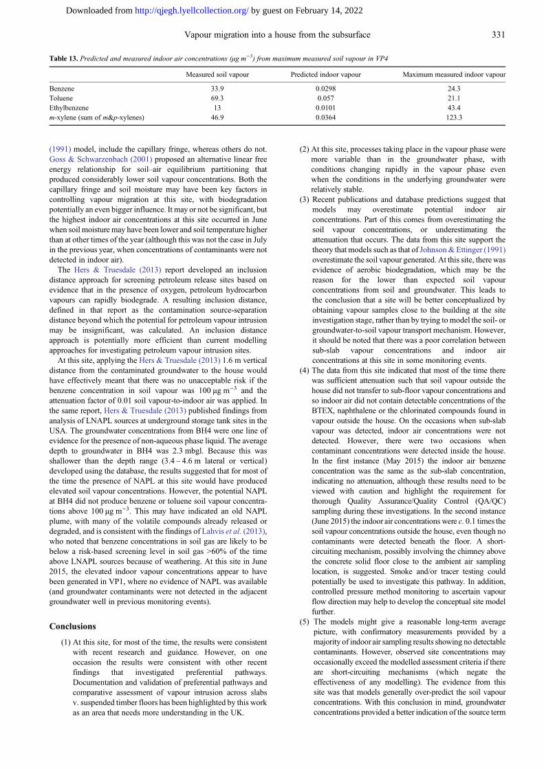
The current UK regulatory tool (CLEA 1.071) software(Environment Agency 2015), which includes the Johnson &Ettinger (1991) model to predict vapour concentrations, has beenused to provide context to the soil results. Selecting a residentialscenario for a female child receptor aged 0–6 years in a smallterraced house on sand geology, using the highest contaminant soilconcentrations from VP4, and using default CLEA values (whichinclude a depth to contamination of 65 cm and a soil organic mattercontent of 6%), the results in Table 12 have been predicted. Table 12also includes a comparison with the maximum soil vapour andambient air values measured in Tables 5 and 7.
Although for the half of the house underlain by a ground bearingslab the site conceptual model was similar to the Johnson & Ettinger(1991) model, the measured soil vapour concentrations in vapourwells immediately outside the house were much lower than those
Table 10. Exceedances of groundwater screening values (µg l−1) for vapourpathway
WSV
BH4,August2013
BH4,September
2013
BH4,July2014
BH4,March2015
Naphthalene 952 1600 2500 580 1200Benzene 88.8 17800 31000 40900 6340
Fig. 6. Biotrap. QuantArray® petroleum study.
329Vapour migration into a house from the subsurface
by guest on February 14, 2022http://qjegh.lyellcollection.org/Downloaded from
predicted by the CLEA model. Beneath the house (both the sectionon a ground bearing slab and the section underlain by a suspendedtimber floor), measured contaminant concentrations were generallyeven lower. The results suggest that the soil vapour concentrationswere over-predicted at this site if soil concentrations were used andthis agrees with McAlary et al. (2011), who suggested that using asoil concentration as starting point, instead of groundwaterconcentration, is not recommended for assessing subsurfacevapour intrusion into a building. However, the maximum observedindoor air concentrations of BTEX compounds on one occasionwere higher than those predicted by almost an order of magnitude.Therefore, the modelling for vapour ingress into buildings may havebeen under-predicting potential maximum indoor air concentrationsif preferential pathways exist.
Measured v. predicted indoor air concentrations using soilvapour concentrations
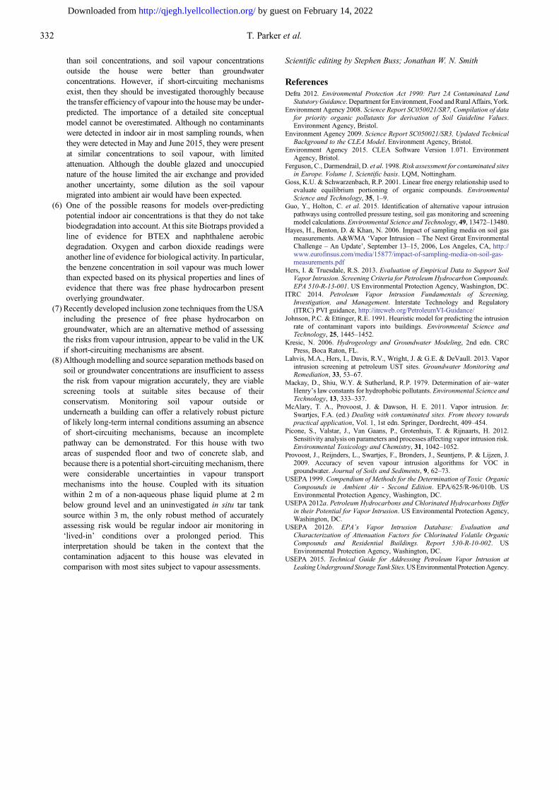
Using the current UK regulatory tool (CLEA 1.071) software butentering soil vapour concentrations from close to the house(excluding VP5, which is c. 15 m from the house) directly intothe model provided the predictions shown in Table 13. Using soilvapour concentrations close to the house is the approach likely to be
taken by many risk assessment practitioners in the UK, becausegoing into a house and taking subfloor samples has the potential tocause blight.
Use of CLEA in this way combines several processes, but insimple terms represented an estimation of the dilution between near-building soil vapour and the house itself. Although most of themonitoring round results agreed with the predictions in Table 13(i.e. no contaminants were routinely detected in indoor air, evenwhen concentrations were detected beneath the house), themaximum observed indoor values exceeded those predicted onone occasion (two for benzene). The results confirmed the soilconcentration modelling that suggested that the model under-predicted the worst-case transport of vapour from the subsurfaceinto this particular house, although at this house there may havebeen a short-circuiting mechanism via the chimney flue above theconcrete floor that meant that modelling was not appropriate.
For an alternative approach to modelling, the USEPA hasassembled a database of empirical sub-slab-to-indoor vapourattenuation factors (USEPA 2012a,b). Although most of the datain this EPA database are for chlorinated solvents, the sub-slabattenuation factors can be applied to petroleum hydrocarbonsbecause little bio-attenuation is expected between sub-slab andindoor air. Sub-slab attenuation factors in the USEPA (2012b)database vary over several orders of magnitude because of spatialand temporal variability in both indoor air and sub-slab vapourconcentrations and background sources of chemicals in indoor air.In the USEPA (2012b) database, the 50th and 95th percentiles of thesub-slab attenuation factor are 5.0 × 10⁻³ and 1.8 × 10⁻¹ respect-ively, when the data are limited to indoor air concentrations above a90th percentile background concentration found in the literature.When the data are limited to sub-slab vapour concentrations greaterthan 100 times the literature background, the 50th and 95thpercentiles of the sub-slab attenuation factor are 2.5 × 10⁻³ and2.0 × 10−2 respectively (USEPA 2012b). Therefore, a shallow soilvapour-to-indoor air attenuation factor of 0.01 is considered areasonably conservative attenuation factor for hydrocarbon andchlorinated contaminants.
At this site the sub-slab vapour concentrations were eitheraccompanied by an absence in the indoor air samples, or a similarconcentration in the indoor air samples (May 2015, but data shouldbe treated with caution). The soil vapour concentrations thereforevaried from more than 100 times higher than the indoor airconcentration to less than 10 times the indoor air concentration. Insummary, although the 0.01 attenuation factor was valid for most ofthe time, in June 2015 the attenuation factor was closer to 0.1.
As noted by Provoost et al. (2009), the inclusion or exclusion of acapillary fringe or temperature correction for the Henry constant inthe mathematical concept could be significant. Volatilization fromthe groundwater could be limited by the diffusion rate through thecapillary fringe, which, besides soil air, also contains porewater.Diffusion coefficients in water are two to four orders of magnitudelower than in air, and some models, like the Johnson & Ettinger
Table 12. Predicted and measured vapour concentrations from maximum measured soil data
Soil values(mg kg−1)
Predicted soilvapour (µg m−3)
Maximum measuredsoil vapour (µg m−3)
Predicted indoorvapour (µg m−3)
Maximum measuredindoor vapour (µg m−3)
Benzene 1.0 44900 33.9 3.94 24.3Toluene 11 172000 69.3 14.2 21.1Ethylbenzene 6.7 59000 13 4.58 43.4m-xylene (sum ofm&p-xylenes)
130 843000 46.9 65.4 123.3
Phenol 730 1970 Not measured 3.03 Not measured
Results from VP5 are not included because this well was c. 15 m from house.
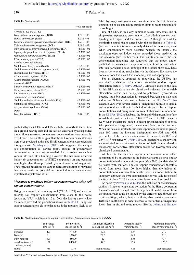
Table 11. Biotrap results
(cells per bead)
Aerobic BTEX and MTBEToluene/benzene dioxygenase (TOD) 1.52E + 05Phenol hydroxylase (PHE) 1.27E + 03Toluene 2 monooxygenase/phenol hydroxylase (RDEG) 1.73E + 03Xylene/toluene monooxygenase (TOL) 1.69E + 03Ethylbenzene/isopropylbenzene dioxygenase (EDO) <2.50E + 02Biphenyl/isopropylbenzene dioxygenase (BPH4) <2.50E + 02Methylibium petroliphilum PM1 (PM1) <2.50E + 02TBA monooxygenase (TBA) <2.50E + 02Aerobic PAHs and alkanesNaphthalene dioxygenase (NAH) 3.25E + 03Naphthalene-inducible dioxygenase (NidA) <2.50E + 02Phenanthrene dioxygenase (PHN) <2.50E + 02Alkane monooxygenase (ALK) <2.50E + 02Alkane monooxygenase (ALMA) <2.50E + 02Anaerobic BTEXBenzoyl coenzyme A reductase (BCR) <2.50E + 02Benzylsuccinate synthase (BSS) <2.50E + 02Benzene carboxylase (ABC) <2.50E + 02Anaerobic PAHs and alkanesNaphthylmethylsuccinate synthase (MNSSA) <2.50E + 02Naphthalene carboxylase (ANC) <2.50E + 02Alklysuccinate synthase (ASSA) <2.50E + 02OtherTotal Eubacteria (EBAC) 6.46E + 06
330 T. Parker et al.
by guest on February 14, 2022http://qjegh.lyellcollection.org/Downloaded from
(1991) model, include the capillary fringe, whereas others do not.Goss & Schwarzenbach (2001) proposed an alternative linear freeenergy relationship for soil–air equilibrium partitioning thatproduced considerably lower soil vapour concentrations. Both thecapillary fringe and soil moisture may have been key factors incontrolling vapour migration at this site, with biodegradationpotentially an even bigger influence. It may or not be significant, butthe highest indoor air concentrations at this site occurred in Junewhen soil moisture may have been lower and soil temperature higherthan at other times of the year (although this was not the case in Julyin the previous year, when concentrations of contaminants were notdetected in indoor air).
The Hers & Truesdale (2013) report developed an inclusiondistance approach for screening petroleum release sites based onevidence that in the presence of oxygen, petroleum hydrocarbonvapours can rapidly biodegrade. A resulting inclusion distance,defined in that report as the contamination source-separationdistance beyond which the potential for petroleum vapour intrusionmay be insignificant, was calculated. An inclusion distanceapproach is potentially more efficient than current modellingapproaches for investigating petroleum vapour intrusion sites.
At this site, applying the Hers & Truesdale (2013) 1.6 m verticaldistance from the contaminated groundwater to the house wouldhave effectively meant that there was no unacceptable risk if thebenzene concentration in soil vapour was 100 µg m−3 and theattenuation factor of 0.01 soil vapour-to-indoor air was applied. Inthe same report, Hers & Truesdale (2013) published findings fromanalysis of LNAPL sources at underground storage tank sites in theUSA. The groundwater concentrations from BH4 were one line ofevidence for the presence of non-aqueous phase liquid. The averagedepth to groundwater in BH4 was 2.3 mbgl. Because this wasshallower than the depth range (3.4 – 4.6 m lateral or vertical)developed using the database, the results suggested that for most ofthe time the presence of NAPL at this site would have producedelevated soil vapour concentrations. However, the potential NAPLat BH4 did not produce benzene or toluene soil vapour concentra-tions above 100 µg m−3. This may have indicated an old NAPLplume, with many of the volatile compounds already released ordegraded, and is consistent with the findings of Lahvis et al. (2013),who noted that benzene concentrations in soil gas are likely to bebelow a risk-based screening level in soil gas >60% of the timeabove LNAPL sources because of weathering. At this site in June2015, the elevated indoor vapour concentrations appear to havebeen generated in VP1, where no evidence of NAPL was available(and groundwater contaminants were not detected in the adjacentgroundwater well in previous monitoring events).
Conclusions
(1) At this site, for most of the time, the results were consistentwith recent research and guidance. However, on oneoccasion the results were consistent with other recentfindings that investigated preferential pathways.Documentation and validation of preferential pathways andcomparative assessment of vapour intrusion across slabsv. suspended timber floors has been highlighted by this workas an area that needs more understanding in the UK.
(2) At this site, processes taking place in the vapour phase weremore variable than in the groundwater phase, withconditions changing rapidly in the vapour phase evenwhen the conditions in the underlying groundwater wererelatively stable.
(3) Recent publications and database predictions suggest thatmodels may overestimate potential indoor airconcentrations. Part of this comes from overestimating thesoil vapour concentrations, or underestimating theattenuation that occurs. The data from this site support thetheory that models such as that of Johnson & Ettinger (1991)overestimate the soil vapour generated. At this site, therewasevidence of aerobic biodegradation, which may be thereason for the lower than expected soil vapourconcentrations from soil and groundwater. This leads tothe conclusion that a site will be better conceptualized byobtaining vapour samples close to the building at the siteinvestigation stage, rather than by trying to model the soil- orgroundwater-to-soil vapour transport mechanism. However,it should be noted that there was a poor correlation betweensub-slab vapour concentrations and indoor airconcentrations at this site in some monitoring events.
(4) The data from this site indicated that most of the time therewas sufficient attenuation such that soil vapour outside thehouse did not transfer to sub-floor vapour concentrations andso indoor air did not contain detectable concentrations of theBTEX, naphthalene or the chlorinated compounds found invapour outside the house. On the occasions when sub-slabvapour was detected, indoor air concentrations were notdetected. However, there were two occasions whencontaminant concentrations were detected inside the house.In the first instance (May 2015) the indoor air benzeneconcentration was the same as the sub-slab concentration,indicating no attenuation, although these results need to beviewed with caution and highlight the requirement forthorough Quality Assurance/Quality Control (QA/QC)sampling during these investigations. In the second instance(June 2015) the indoor air concentrations were c. 0.1 times thesoil vapour concentrations outside the house, even though nocontaminants were detected beneath the floor. A short-circuiting mechanism, possibly involving the chimney abovethe concrete solid floor close to the ambient air samplinglocation, is suggested. Smoke and/or tracer testing couldpotentially be used to investigate this pathway. In addition,controlled pressure method monitoring to ascertain vapourflow direction may help to develop the conceptual site modelfurther.
(5) The models might give a reasonable long-term averagepicture, with confirmatory measurements provided by amajority of indoor air sampling results showing no detectablecontaminants. However, observed site concentrations mayoccasionally exceed the modelled assessment criteria if thereare short-circuiting mechanisms (which negate theeffectiveness of any modelling). The evidence from thissite was that models generally over-predict the soil vapourconcentrations. With this conclusion in mind, groundwaterconcentrations provided a better indication of the source term
Table 13. Predicted and measured indoor air concentrations (µg m−3) from maximum measured soil vapour in VP4
Measured soil vapour Predicted indoor vapour Maximum measured indoor vapour
Benzene 33.9 0.0298 24.3Toluene 69.3 0.057 21.1Ethylbenzene 13 0.0101 43.4m-xylene (sum of m&p-xylenes) 46.9 0.0364 123.3
331Vapour migration into a house from the subsurface
by guest on February 14, 2022http://qjegh.lyellcollection.org/Downloaded from
than soil concentrations, and soil vapour concentrationsoutside the house were better than groundwaterconcentrations. However, if short-circuiting mechanismsexist, then they should be investigated thoroughly becausethe transfer efficiency of vapour into the housemay be under-predicted. The importance of a detailed site conceptualmodel cannot be overestimated. Although no contaminantswere detected in indoor air in most sampling rounds, whenthey were detected in May and June 2015, they were presentat similar concentrations to soil vapour, with limitedattenuation. Although the double glazed and unoccupiednature of the house limited the air exchange and providedanother uncertainty, some dilution as the soil vapourmigrated into ambient air would have been expected.
(6) One of the possible reasons for models over-predictingpotential indoor air concentrations is that they do not takebiodegradation into account. At this site Biotraps provided aline of evidence for BTEX and naphthalene aerobicdegradation. Oxygen and carbon dioxide readings wereanother line of evidence for biological activity. In particular,the benzene concentration in soil vapour was much lowerthan expected based on its physical properties and lines ofevidence that there was free phase hydrocarbon presentoverlying groundwater.
(7) Recently developed inclusion zone techniques from the USAincluding the presence of free phase hydrocarbon ongroundwater, which are an alternative method of assessingthe risks from vapour intrusion, appear to be valid in the UKif short-circuiting mechanisms are absent.
(8) Althoughmodelling and source separationmethods based onsoil or groundwater concentrations are insufficient to assessthe risk from vapour migration accurately, they are viablescreening tools at suitable sites because of theirconservatism. Monitoring soil vapour outside orunderneath a building can offer a relatively robust pictureof likely long-term internal conditions assuming an absenceof short-circuiting mechanisms, because an incompletepathway can be demonstrated. For this house with twoareas of suspended floor and two of concrete slab, andbecause there is a potential short-circuiting mechanism, therewere considerable uncertainties in vapour transportmechanisms into the house. Coupled with its situationwithin 2 m of a non-aqueous phase liquid plume at 2 mbelow ground level and an uninvestigated in situ tar tanksource within 3 m, the only robust method of accuratelyassessing risk would be regular indoor air monitoring in‘lived-in’ conditions over a prolonged period. Thisinterpretation should be taken in the context that thecontamination adjacent to this house was elevated incomparison with most sites subject to vapour assessments.
Scientific editing by Stephen Buss; Jonathan W. N. Smith
ReferencesDefra 2012. Environmental Protection Act 1990: Part 2A Contaminated Land
StatutoryGuidance. Department for Environment, Food andRuralAffairs,York.Environment Agency 2008. Science Report SC050021/SR7, Compilation of data
for priority organic pollutants for derivation of Soil Guideline Values.Environment Agency, Bristol.
Environment Agency 2009. Science Report SC050021/SR3, Updated TechnicalBackground to the CLEA Model. Environment Agency, Bristol.
Environment Agency 2015. CLEA Software Version 1.071. EnvironmentAgency, Bristol.
Ferguson, C., Darmendrail, D. et al. 1998. Risk assessment for contaminated sitesin Europe. Volume 1, Scientific basis. LQM, Nottingham.
Goss, K.U. & Schwarzenbach, R.P. 2001. Linear free energy relationship used toevaluate equilibrium portioning of organic compounds. EnvironmentalScience and Technology, 35, 1–9.
Guo, Y., Holton, C. et al. 2015. Identification of alternative vapour intrusionpathways using controlled pressure testing, soil gas monitoring and screeningmodel calculations. Environmental Science and Technology, 49, 13472–13480.
Hayes, H., Benton, D. & Khan, N. 2006. Impact of sampling media on soil gasmeasurements. A&WMA ‘Vapor Intrusion – The Next Great EnvironmentalChallenge – An Update’, September 13–15, 2006, Los Angeles, CA, http://www.eurofinsus.com/media/15877/impact-of-sampling-media-on-soil-gas-measurements.pdf
Hers, I. & Truesdale, R.S. 2013. Evaluation of Empirical Data to Support SoilVapor Intrusion. Screening Criteria for Petroleum Hydrocarbon Compounds.EPA 510-R-13-001. US Environmental Protection Agency, Washington, DC.
ITRC 2014. Petroleum Vapor Intrusion Fundamentals of Screening,Investigation, and Management. Interstate Technology and Regulatory(ITRC) PVI guidance, http://itrcweb.org/PetroleumVI-Guidance/
Johnson, P.C. & Ettinger, R.E. 1991. Heuristic model for predicting the intrusionrate of contaminant vapors into buildings. Environmental Science andTechnology, 25, 1445–1452.
Kresic, N. 2006. Hydrogeology and Groundwater Modeling, 2nd edn. CRCPress, Boca Raton, FL.
Lahvis, M.A., Hers, I., Davis, R.V., Wright, J. & G.E. & DeVaull. 2013. Vaporintrusion screening at petroleum UST sites. Groundwater Monitoring andRemediation, 33, 53–67.
Mackay, D., Shiu, W.Y. & Sutherland, R.P. 1979. Determination of air–waterHenry’s law constants for hydrophobic pollutants. Environmental Science andTechnology, 13, 333–337.
McAlary, T. A., Provoost, J. & Dawson, H. E. 2011. Vapor intrusion. In:Swartjes, F.A. (ed.) Dealing with contaminated sites. From theory towardspractical application, Vol. 1, 1st edn. Springer, Dordrecht, 409–454.
Picone, S., Valstar, J., Van Gaans, P., Grotenhuis, T. & Rijnaarts, H. 2012.Sensitivity analysis on parameters and processes affecting vapor intrusion risk.Environmental Toxicology and Chemistry, 31, 1042–1052.
Provoost, J., Reijnders, L., Swartjes, F., Bronders, J., Seuntjens, P. & Lijzen, J.2009. Accuracy of seven vapour intrusion algorithms for VOC ingroundwater. Journal of Soils and Sediments, 9, 62–73.
USEPA 1999. Compendium of Methods for the Determination of Toxic OrganicCompounds in Ambient Air - Second Edition. EPA/625/R-96/010b. USEnvironmental Protection Agency, Washington, DC.
USEPA 2012a. Petroleum Hydrocarbons and Chlorinated Hydrocarbons Differin their Potential for Vapor Intrusion. US Environmental Protection Agency,Washington, DC.
USEPA 2012b. EPA’s Vapor Intrusion Database: Evaluation andCharacterization of Attenuation Factors for Chlorinated Volatile OrganicCompounds and Residential Buildings. Report 530-R-10-002. USEnvironmental Protection Agency, Washington, DC.
USEPA 2015. Technical Guide for Addressing Petroleum Vapor Intrusion atLeakingUndergroundStorageTankSites.USEnvironmentalProtectionAgency.
332 T. Parker et al.
by guest on February 14, 2022http://qjegh.lyellcollection.org/Downloaded from