Embed Size (px)
Citation preview

Real Time Positioning; Construction and implementation of a GPS-Communicator.
Master’s thesis in Control and Communication
By
Christian Darnell Christian Wilczoch
Report no. LITH-ISY-EX-3246-2002
Linköping 2002-06-07
Real Time Positioning; Construction and implementation of a GPS-Communicator.
Master’s thesis in Control and Communication
By
Christian Darnell Christian Wilczoch
Report no. LITH-ISY-EX-3246-2002
Linköping 2002-06-07
Supervisors: Mikael Göthammer KORDAB Examiner: Ulf Henriksson LiTH

Avdelning, Institution Division, Department
Institutionen för Systemteknik 581 83 LINKÖPING
Datum
2002-06-07
Språk Language
RapporttypReport category
ISBN
Svenska/Swedish X Engelska/English
Licentiatavhandling X Examensarbete
LITH-ISY-EX-3246-2002
C-uppsats D-uppsats
Serietitel och serienummer Title of series, numbering
Övrig rapport
URL för elektronisk versionhttp://www.ep.liu.se/exjobb/isy/2002/3246/
Titel Title
Realtidspositionering; Utveckling av en GPS-kommunikator. Real Time Positioning; Construction and implementation of a GPS-Communicator.
Författare Author
Christian Darnell Christian Wilczoch
Abstract The first half of this Master’s thesis is the result of a survey made on the behalf of the Swedish company KORDAB International AB. The survey includes an overview of different positioning systems and some wireless communication techniques available on the market today. The positioning systems discussed are GPS, DGPS, AGPS and GSM. Mobile Internet connections through mobile phones and communication via radio modems are mentioned and described as examples of wireless communication techniques. Examples of techniques described are HSCSD, GPRS, UMTS and MOBITEX. KORDAB is in the starting blocks and ready to implement a real time positioning feature into their own technical information system GEOSECMA. This survey will give them a foundation that will help them to decide on which system to use for this feature. The second half of the thesis includes sections dealing with a prototype made to exemplify how KORDAB could implement the real time positioning feature into GEOSECMA. The NMEA 0183 protocol, reference systems and transformation are described to give the necessary background knowledge for the construction and functionality of the prototype. The prototype is a GPS-communicator made as an interface between a GPS-receiver and GEOSECMA and its functionality is also described in this second half of the thesis. Feasible applications are also discussed to show the possibilities real time positioning gives. One application discussed is “Zoom and Auto Highlighting”. This application is designed to help the user of GEOSECMA to zoom in the map and highlight the nearest object at the current location.
Keyword GPS, RTK, DGPS, AGPS, GSM-positioning, Real Time Positioning, TOA, TDOA, EOTD, AOA, GSM, HSCSD, GPRS, UMTS, Mobitex, NMEA 0183, GGA, GSV, WGS84, SWEREF99, RT90, GPS-Communicator

Real Time Positioning; Construction and implementation of a GPS-Communicator
ii
Abstract The first half of this Masters thesis is the result of a survey made on the behalf of the Swedish company KORDAB International AB. The survey includes an overview of different positioning systems and some wireless communication techniques available on the market today. The positioning systems discussed are GPS, DGPS, AGPS and GSM positioning. Mobile Internet connections through mobile phones and communication via radio modems are mentioned and described as examples of wireless communication techniques. Examples of techniques described are HSCSD, GPRS, UMTS and MOBITEX.
KORDAB is in the starting blocks and ready to implement a real time positioning feature into their own technical information system GEOSECMA. This survey will give them a foundation that will help them to decide which system to use for this feature.
The second half of the thesis includes sections dealing with a prototype made to exemplify how KORDAB could implement the real time positioning feature into GEOSECMA. The NMEA 0183 protocol, reference systems and transformation of coordinates are described to give the necessary background knowledge for the construction and functionality of the prototype. The prototype is a GPS-communicator made as an interface between a GPS-receiver and GEOSECMA and its functionality is also described in this second half of the thesis. Feasible applications are also discussed to show the possibilities real time positioning gives. One application discussed is “Zoom and Auto Highlighting”. This application is designed to help the user of GEOSECMA to zoom in the map and highlight the nearest object at the current location.
Real Time Positioning; Construction and implementation of a GPS-Communicator
iii
Acknowledgements We would like to thank our tutor Ulf Henriksson (Head of Department at ISY, Linköping University) for his support and help during our work. He has given us the moral support to finish this report and above all ideas, viewpoints and comments to improve our thesis. We would also like to thank our opponents Per Klintenstedt and Mattias Engberg for their comments.
We are grateful for the opportunity KORDAB has given us by letting us work with this project. A thanks to our supervisor Mikael Göthammer and all the others at KORDAB who have supported us during the work there.
A special thanks to Lindy Gustavsson for her help with the proofreading.

Real Time Positioning; Construction and implementation of a GPS-Communicator
iv
Table of contents 1 Introduction 1
1.1 Aims ....................................................................................................... 2
1.2 Goals....................................................................................................... 3
1.3 Limitations .............................................................................................. 3
1.4 Disposition.............................................................................................. 3
2 Positioning methods 5
2.1 GPS......................................................................................................... 5
2.1.1 GPS Satellites ..................................................................................................... 6
2.1.2 Technical overview............................................................................................. 7
2.1.3 Necessary equipment, accuracy, price and output.............................................. 14
2.1.4 Future of the GPS system.................................................................................. 15
2.2 Differential GPS.................................................................................... 16
2.2.1 Typical Equipment ........................................................................................... 18
2.2.2 Economic aspects ............................................................................................. 19
2.2.3 RTK GPS ......................................................................................................... 20
2.2.4 Real Time Services ........................................................................................... 23
2.2.5 Post processing ................................................................................................. 26
2.2.6 Network RTK................................................................................................... 26
2.3 AGPS.................................................................................................... 28
2.3.1 System structure ............................................................................................... 28
2.3.2 Accuracy .......................................................................................................... 28
2.4 Mobile Positioning System ................................................................... 29
2.4.1 Cell Global Identity-Timing Advance ............................................................... 29
2.4.2 Time Of Arrival................................................................................................ 30
2.4.3 Time Difference of Arrival ............................................................................... 30
2.4.4 Enhanced Observed Time Difference................................................................ 31
2.4.5 Angle Of Arrival............................................................................................... 32
Real Time Positioning; Construction and implementation of a GPS-Communicator
v
3 Communication links 33
3.1 Mobile Internet Connection................................................................... 33
3.1.1 GSM................................................................................................................. 33
3.1.2 HSCSD............................................................................................................. 33
3.1.3 GPRS ............................................................................................................... 34
3.1.4 UMTS .............................................................................................................. 35
3.2 Mobitex (radio modem) ........................................................................ 36
3.2.1 Narrowband...................................................................................................... 36
3.2.2 Dedicated data .................................................................................................. 36
3.2.3 Packet-switched system .................................................................................... 36
3.3 Internal radio modem network .............................................................. 37
4 NMEA 0183 protocol 38
4.1 NMEA electrical interface..................................................................... 38
4.2 General sentence format........................................................................ 39
4.2.1 Talker sentence................................................................................................. 39
4.2.2 Proprietary sentences ........................................................................................ 39
4.2.3 Query sentence ................................................................................................. 39
4.3 Talker identifiers ................................................................................... 40
4.4 Sentence identifier and formats ............................................................. 40
4.4.1 ALM GPS Almanac Data ................................................................................. 40
4.4.2 BWC Bearing and Distance to Waypoint .......................................................... 41
4.4.3 GGA Global Positioning System Fix Data ........................................................ 42
4.4.4 GSV Satellites in view...................................................................................... 43
4.5 Proprietary sentences ............................................................................ 44
4.5.1 $PGRMC Sensor Configuration Information .................................................... 44
4.5.2 $PGRME Estimated Position Error................................................................... 45
5 Reference systems and transformation 46
5.1 Reference systems................................................................................. 46
Real Time Positioning; Construction and implementation of a GPS-Communicator
vi
5.1.1 WGS84............................................................................................................. 46
5.1.2 ETRS89............................................................................................................ 47
5.1.3 SWEREF 99 ..................................................................................................... 47
5.1.4 RT90 ................................................................................................................ 47
5.1.5 RH70................................................................................................................ 47
5.2 Transformation...................................................................................... 48
5.2.1 Horizontal......................................................................................................... 48
5.2.2 Vertical............................................................................................................. 51
6 Possible applications 52
6.1 Restricted users ..................................................................................... 52
6.2 Public users ........................................................................................... 54
7 Recommendations 56
7.1 Positioning methods to use.................................................................... 56
7.2 Communication link to use.................................................................... 56
7.3 Interface ................................................................................................ 57
7.4 Application ........................................................................................... 57
8 Prototype 58
8.1 Init(port,baud) ....................................................................................... 60
8.2 AutoInit() .............................................................................................. 61
8.3 GetGPSdata(x,y,z,ns,ew) ...................................................................... 62
8.4 Free ....................................................................................................... 64
8.5 Typical uses of the interface.................................................................. 65
9 Conclusions 66
10 Tips 67
10.1 Simulate a GPS .................................................................................. 67
10.2 GPS utilities ....................................................................................... 68
10.3 GPS satellite prediction ...................................................................... 68
11 References 70
Real Time Positioning; Construction and implementation of a GPS-Communicator
vii
12 Appendix 74
12.1 Simulate a GPS with a terminal program............................................ 74
12.1.1 Physical Connection ...................................................................................... 74
12.1.2 Setup connection ........................................................................................... 75
12.1.3 Send file ........................................................................................................ 78
12.1.4 Log file.......................................................................................................... 79
12.2 Classes specific to the prototype package ........................................... 81
12.2.1 Class CGPSReadData.................................................................................... 81
12.2.2 Class GGA .................................................................................................... 82
12.2.3 Class GPSdata ............................................................................................... 84
12.2.4 Class RS232_COM ....................................................................................... 84
12.2.5 Class SENTENCE......................................................................................... 86
12.3 Transformation: SWEREF99 to RT90................................................ 88
12.4 Test measurement............................................................................... 90
Real Time Positioning; Construction and implementation of a GPS-Communicator
1
1 Introduction
The Swedish company KORDAB International AB is the parent company of the KORDAB group. The group was founded in 1982 and also includes some smaller totally owned affiliated companies in Poland and Lithuania.
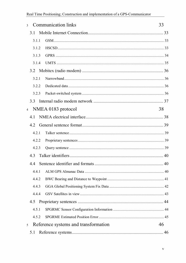
Through their own technical information system GEOSECMA, KORDAB has developed and become the leading Swedish software development company within the field of community planning. GEOSECMA is a modern tool for those who – with the map as the basis – plan, project, construct and manage landscaping installations.
GEOSECMA is an open system and has a Windows environment, routines for data communication and an easily-accessed database. This means that interaction between colleagues, business partners and other software is easily accomplished. The program is built as a modular program system consisting of 13 program packages and the common basis is a central database. The system is also a multi-user system, which implies that many users are allowed to simultaneously create and edit data within the same area. Each user can choose the frequency at which the screen image should be updated with current data from the database. Colleagues in different departments will in this way always have access to updated information.
Figure 1.1 – Illustration of GEOSECMA
The figure above is an illustration of GEOSECMA and shows its basic structure. The I-core running through the middle is the base to which the core functions are connected.
This thesis is the result of the RTPG (Real Time Positioning in GEOSECMA) project performed at KORDAB. The following chapter will give you a brief introduction to the KORDAB company. We will also introduce the criteria and contents of the project.

Real Time Positioning; Construction and implementation of a GPS-Communicator
2
There are, at this time, twelve base functions that can be connected, each with its specific orientation towards a special area with its own functionality. The specialised functionality required by each application is developed individually.
The bottom of the figure shows that the base functions communicate with a database and that they are capable of interaction between other softwares like MS Office, ArcView etc.
The top of the figure shows the two different types of layers for presentation. The first is the main layer used to present information to the user. A second layer is also available, the web layer. This layer makes it possible for field workers to use GEOSECMA on any field computer connected to the Internet. It is also possible to access the database and share the same information as the colleagues at office.
It is now also desirable to get real-time positioning data to the web application. The position is required to either update or create a new object or just to give the field worker an idea about where he/she is located. This means that some extra equipment and some additional code to the software in GEOSECMA are needed. This is what this Master thesis is all about. In this report we will give a survey of which positioning systems there are available and also try to find the lowest common dominator for the position data that they deliver. We will also describe how to send the position data to GEOSECMA.
1.1 Aims
KORDAB wants a survey of which positioning system that can be connected with the web application of GEOSECMA. They also want to know which communication link to use to provide GEOSECMA with the position data. The lowest common dominator of the delivered position data are also of interest. In other words, how shall they build the interface to receive the position data? Another interesting question is what kind of usage real-time positioning could lead to. The figure below tries to summarise the main questions asked by KORDAB.
Figure 1.2 – Graphical summation of questions asked by KORDAB.
Real Time Positioning; Construction and implementation of a GPS-Communicator
3
This Master’s thesis will hopefully give the answer to KORDAB’s questions in a satisfactory way.
1.2 Goals
The main goal with this Master’s thesis is to answer KORDAB’s questions. We will at least give answer to the questions they ask and give them an idea of what they want. We will also try to implement an interface to receive position data into GEOSECMA.
1.3 Limitations
We have decided to only make an interface for a positioning system that has a world wide standard. KORDAB is not interested in implementing an interface that does not follow any accepted standardisation. That could in the long run give expensive extra costs when changes must be made. Another reason is that they do not want to be dependent on a specific product. Each product will probably have its own interface and it would require too much work to implement support for all possible interfaces.
1.4 Disposition
Chapter 1 Introduction This thesis is the result of the RTPG (Real Time Positioning in GEOSECMA) project performed at KORDAB. The following chapter will give you a brief introduction to the company KORDAB. We will also introduce the criteria and contents of the project.
Chapter 2 Positioning methods The Positioning methods chapter will give a survey of different possible positioning methods. The methods might be of interest to use in GEOSECMA. The enumeration methods are GPS, DGPS, GSM-positioning and AGPS.
Chapter 3 Communication links The Communication links chapter will describe different communication links that might be used to establish a connection with the field application. The communication links described here are the ones we think are most suitable today or in the near future. Of course there are other possible techniques that might be used, such as Wireless LAN (802.11b) or a satellite modem using the ORBCOMM satellite network (global coverage). These systems/techniques will not be described here.
Chapter 4 NMEA 0183 protocol The NMEA 0183 protocol chapter will discuss the NMEA protocol. We will give a few examples of different messages to show the typical structure. Positioning units like GPS- and DGPS receivers use this protocol.
Chapter 5 Reference systems and transformation The Reference systems and transformation chapter will describe different reference systems and discuss why different systems exist. It will also describe how to transfer coordinates from SWEREF99 (WGS84) to RT90 and RH70, which are local references systems used in Sweden. This chapter will not discuss or elaborate

Real Time Positioning; Construction and implementation of a GPS-Communicator
4
on the meaning of the following conceptions: ellipsoid, geoid, geodetic coordinates, geocentric coordinates, plane coordinates, semi-major axis, inverse flattening, isometric latitude, first eccentricity squared and radius of curvature in the prime vertical.
Chapter 6 Possible applications The ability to get a position in real time gives many opportunities for applications. We will here point out some examples to show the enormous potentials this could give GEOSECMA.
Chapter 7 Recommendations The Recommendations chapter includes our recommendations to KORDAB based on the results during the preliminary study on existing positioning units, communication alternatives and usable applications.
Chapter 8 Prototype The Prototype chapter will describe our prototype interface for GPS and DGPS-receivers. The prototype was made as an example to show how an interface might be constructed. The prototype is, at the moment, only working on computers with Windows 9x- and NT-based operating systems. Implementation for Windows CE is not yet implemented.
Chapter 9 Conclusions The conclusion chapter includes our conclusions based on our survey and work. It is basically a summery of chapter 7 and 8.
Chapter 10 Tips The Tips chapter will give a few tips that can be useful for those who are new to GPS-receivers.
Chapter 11 Reference Chapter 12 Appendix

Real Time Positioning; Construction and implementation of a GPS-Communicator
5
2 Positioning methods
2.1 GPS
In the early 1970's, the United States military began to develop a satellite navigation-system, originally for military purposes. This system replaced the old system called TRANSIT because of two major shortcomings in that system (large time gaps in coverage and low navigation accuracy). The Global Positioning System (GPS) was developed by the US Department of Defense (DoD) as a worldwide navigation and positioning facility. The first satellite was launched on February 22 in 1978 and was called NAVSTAR 1. The satellite type used in the Global Positioning System today is also called NAVSTAR and it stands for Navigation Satellite Time and Ranging Global Positioning System.
GLONASS (GLObal NAvigation Satellite System) is, like GPS, a satellite-based radio-navigation system. The system is developed and maintained by the Russian Space Forces. GLONASS has, like GPS, two types of navigation signal: a standard precision navigation signal (SP) and a high precision navigation signal (HP). SP positioning and timing services are available to civilian users and provide a horizontal positioning accuracy within 57-70 meters (99.7% confidence interval), and vertical positioning accuracy within 70 meters (99.7 confidence interval).
Unlike the GPS system each GLONASS satellite has its own frequency, though satellites can have the same frequencies if they are placed in antipodal slots of the orbit planes (so they not appear at the same time in the user’s view).
The GLONASS satellites are placed in three orbital planes whose ascending nodes are 120 degrees apart and orbiting earth in 11 hours and 15 minutes. The GLONASS system should contain 24 satellites when fully operational, but the current status (2002-08-19) of the system is seven operational satellites in orbit. Due to this the coverage is not global and depending on economic aspects it might never be.
Galileo is planned to be Europe's own global satellite navigation system. The system will provide a highly accurate, guaranteed global positioning service for civilian users and the system will also stand under civilian control. The system will be inter-operable with the GPS- and the GLONASS system.
By offering dual frequencies as standard, the system will be able to deliver real time positioning down to four metres. A new feature in the Galileo system is that the user will be informed within six seconds of the failure of any satellite.
When the system is fully operational (probably in 2008) it will consist of 30 satellites positioned in three orbital planes. There will be 27 operational satellites and three active
This chapter will give a survey of different possible positioning methods. The methods might be of interest to use in GEOSECMA. The enumeration methods are GPS, DGPS, GSM-positioning and AGPS. The following references are of interest for this chapter: GPS[1, 2, 4, 26, 27, 28] DGPS[3, 14, 29-33, 38-40, 44-46], AGPS[10], GSMpos[41-43].

Real Time Positioning; Construction and implementation of a GPS-Communicator
6
spares. These active spare satellites will ensure that a loss of one satellite has no discernible effect on the user. The first satellite is planned to be launched in late 2004.
Due to the optimisation of the constellation for this large number of satellites the system will have good coverage even at latitudes up to 75 degrees north (North Cape and beyond).
Only the GPS system will be discussed further because of the uncertain future of the GLONASS system and the fact that the Galileo is system not yet operational.
2.1.1 GPS Satellites
The Global Positioning System contains 31 satellites orbiting the earth at a height of 20200 kilometres. These satellites are placed in six different orbital planes with an inclination of 55 degrees with respect to the equatorial plane. The satellites circulate earth in 12 hours (sidereal). Thus the satellites are moving at a speed of approximately 10 500 km/h. Each satellite weighs about 1 800 kg to 2 200 kg. The width between the satellites wingspan is from 5 to 10 metres. The solar panels of the satellite generate about 800 Watts. Replacement satellites are constantly launched into orbit, a GPS satellite’s life time is from 7.5 to 10 years.
The transmit power for the NAVSTAR satellite is 50 Watts or less. Each satellite has an extremely accurate atomic clock that is synchronized to all other satellite clocks and to the ground control stations. These clocks are very expensive (about $100 000 each) and each satellite has two cesium clocks and two rubidium clocks.
2.1.1.1 Satellite signal The GPS satellites produce the fundamental L-band frequency of 10.23 MHz. From this fundamental frequency the L1 and L2 signals are created, multiplying the fundamental frequency by 154 and 120 respectively gives:
MHzLMHzL
60.1227242.15751
==
Due to the spread spectrum characteristic of the signals, the system has a large margin of resistance to interference.
2.1.1.2 PRN code Each satellite uses two PRN (Pseudo Random Noise) codes, they are called the C/A-code and P-code. The P-code is only for military use so it will only be mentioned shortly. These codes have the characteristics of random noise but they are in fact very precisely defined. There are 37 PRN sequences used for the C/A-code and each satellite has its own. The satellite broadcasts its code over and over again. This code contains no data; it is just an identifier.
On the L1 frequency the Standard Positioning Service (SPS) will be provided. SPS is a positioning and timing service that contains the two codes. The C/A-code is available for civilian use. SPS is available worldwide without any charges. From the year 2003 the C/A-code will also be available on the L2 frequency. Three years after that there will be a new third frequency L5 for civilian use. The military frequencies will be separated from civilian frequencies in the new system. A new GPS receiver is required to use this system, thus with a old GPS receiver one cannot achieve the benefits of the new system. With the new
Real Time Positioning; Construction and implementation of a GPS-Communicator
7
system, using two frequencies and Differential GPS (See Chapter 2.2 Differential GPS) the position assurance will be approximately 30 centimetres.
The P-code is transmitted on both L1 and L2 frequencies. On these frequencies the Precise Positioning Service (PPS) will be provided. With PPS it is possible to achieve a positioning accuracy of 22 metres horizontally, 27.7 metres vertically and time transfer accuracy within 200 ns.
The satellites transmit a navigation message that essentially is the satellite clock, system time, its orbital elements, various correction data and health status. The total message contains 1 500 bits (transmission rate for the message is 50 bits/s) and it is divided into five sub frames. Sub frame number one contains the GPS week number, a prediction of the user range accuracy, the satellite health, clock correction, the age of the data and an estimation of the signal group delay. The second and third sub frame contains orbital data (ephemeris data parameters) for the transmitting. The contents of the fourth and fifth sub frame are changed in every message. It can for example contain information about the ionosphere (this will be mentioned later), various flags and almanac data for all 31 satellites in orbit. Each satellite therefore broadcasts the fourth and fifth sub frames. Almanac data of all other satellites in orbit are therefore obtained once the first satellite has been acquired.
2.1.1.3 Selective Availability (SA) Selective Availability is the term used to describe the intentional degradation of the GPS signals that are sent by the satellites. This function was imposed by DoD to reduce the inherent accuracy of GPS signals for defense reasons. To lower the accuracy of the C/A-code the DoD added noise to the satellite clock and truncation of the orbital information in the transmitted navigation message, so that the coordinates of the satellites could not be accurately calculated.
With SA enabled the SPS provides a positioning accuracy of 100 metres (95% confident interval) horizontally, 156 metres (95% confident interval) vertically and a time transfer accuracy within 340 ns (95% confident interval).
On May 1st, 2000 president Bill Clinton announced that the United States will stop the intentional degradation of the SPS signals available to the public. This means that after May 1st 2000, civilians can get a positioning accuracy like that in the PPS system.
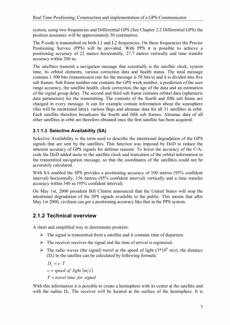
2.1.2 Technical overview
A short and simplified way to determinate position:
The signal is transmitted from a satellite and it contains time of departure. The receiver receives the signal and the time of arrival is registered.
The radio waves (the signal) travel at the speed of light (3*108 m/s), the distance (Ds) to the satellite can be calculated by following formula:
( )signalfortimetravelT
smlightofspeedcTcDs
==
⋅=
With this information it is possible to create a hemisphere with its center at the satellite and with the radius Ds. The receiver will be located at the surface of the hemisphere. It is

Real Time Positioning; Construction and implementation of a GPS-Communicator
8
possible to get a 2D position if this is repeated with three satellites and with use of four satellites a 3D position.
Real Time Positioning; Construction and implementation of a GPS-Communicator
9
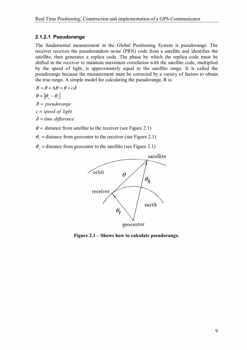
2.1.2.1 Pseudorange The fundamental measurement in the Global Positioning System is pseudorange. The receiver receives the pseudorandom noise (PRN) code from a satellite and identifies the satellite, then generates a replica code. The phase by which the replica code must be shifted in the receiver to maintain maximum correlation with the satellite code, multiplied by the speed of light, is approximately equal to the satellite range. It is called the pseudorange because the measurement must be corrected by a variety of factors to obtain the true range. A simple model for calculating the pseudorange, R is:
differencetimelightofspeedc
epseudorangR
cR
rs
===
−=+=∆+=
δ
θθθδθθθ
=θ distance from satellite to the receiver (see Figure 2.1)
=rθ distance from geocenter to the receiver (see Figure 2.1)
=sθ distance from geocenter to the satellite (see Figure 2.1)
Figure 2.1 – Shows how to calculate pseudorange.

Real Time Positioning; Construction and implementation of a GPS-Communicator
10
2.1.2.2 Triangulation GPS receivers on earth use GPS satellites as reference points for triangulating a precise position on earth. Two satellite measurements determine an intersection of two spheres. This intersection will be a circle and the receiver will be located somewhere on this circle. See Figure 2.2.
Figure 2.2 – The receiver will be located somewhere inside the black circle created by the intersection between the two spheres.
A third satellite’s sphere cuts through the circle created by the first two spheres, in this way we get two intersection points. See Figure 2.3. The receiver is located on either of these two points. These two points are actually enough to determine the position (2D position) of the receiver. This is because one of the points is not reasonable. With a fourth satellite there is no problem to determine the exact point of the receiver (3D position).
Figure 2.3 – A third satellite’s sphere intersects with the verge of the circle created by the other two satellites at two points. The receiver is located at one of these points.

Real Time Positioning; Construction and implementation of a GPS-Communicator
11
2.1.2.2.1 Example triangulation
The following example shows how to determine a 2D position with three satellites. Though in reality the GPS can deliver a 3D position.
The clock in the GPS receiver is not perfect, actually it is often an inexpensive quartz crystal clock. Assume that the receiver’s clock is one second fast. Let us say for the sake of simplicity that the receiver is located one second from satellite S1 and two seconds from satellite S2 (hence in reality the time is shorter). The receiver is located at the point X, see Figure 2.4.
Figure 2.4 – The actual location of the receiver is at point X.
Because the receiver’s clock is one second fast, the two circles will intersect at a different point Y (see Figure 2.5). This is not the actual location of the receiver but because of the time delay it seems as though it would be the correct location.
Figure 2.5 – Due to the clock drift it seems as though the receiver is located at point Y.
If one more satellite S3 is used and if the receiver is three seconds away from it, the intersection point will be X, see Figure 2.6.
Figure 2.6 – A third satellite intersecting at the actual location X.

Real Time Positioning; Construction and implementation of a GPS-Communicator
12
Because the receiver’s clock is one second fast satellites S1 and S2 will still intersect at point Y, satellite S3 will not intersect at the same point as S1 and S2 (see Figure 2.7). The receiver calculates all series of measurements and realizes that something must be wrong. The receiver can manage to calculate the location by adding or subtracting time to find its actual location. Thus, by using a fourth satellite it is possible to cancel out any consistent clock errors the receiver may have.
Figure 2.7 – Due to the clock drift the third satellite will not intersect with point Y.
Real Time Positioning; Construction and implementation of a GPS-Communicator
13
2.1.2.3 Control segment The Operational Control System (OCS) consists of a master control station, monitor stations and ground control stations. The tasks of OCS are:
Tracking the satellites in orbit.
Time synchronization of the satellites. Clock determination and prediction.
Uploading data and messages to the satellites. The OCS also used to impose the SA signal on the broadcast signals.
2.1.2.3.1 Master control station
The master control station is located at the Consolidated Space Operations Center (CSOC) in Colorado Springs, Colorado, USA. CSOC collects data from the monitor stations around the world and calculates the clock parameters and the satellites orbit. The results of these calculations are passed to ground control stations (there are three) for eventual upload to the satellites. CSOC also handle the satellite control and system operation. If a satellite stops working the CSOC have the responsibility for what should be done.
2.1.2.3.2 Monitor stations
There are five monitor stations located around the world. These are located at Hawaii, Colorado Springs, the Ascension Islands in the South Atlantic Ocean, Diego Garcia in the Indian Ocean and Kwajalein in the North Pacific Ocean. These stations are equipped with a precise cesium time. This is used to measure pseudoranges to all satellites in view. The data are transmitted to the master control station.
2.1.2.3.3 Ground control stations
The ground control stations are located at the monitor stations at the Ascension Islands, Diego Garcia and Kwajalein. They are communication links to the satellites and have ground antennas. They upload data received from the master control station to the satellites via S-band radio links.
2.1.2.4 Bias Errors Bias errors can accrue by clock errors uncorrected by Control Segment and can result in up to one metre errors in position.
2.1.2.4.1 Atmospheric effects
GPS satellite signals are slowed by the Earth's atmosphere, which results in a delay in the arrival time of the transmitted signal from that expected if there were no intervening media.
2.1.2.4.1.1 Ionosphere
In the ionosphere about 50 to 1 000 kilometres above earth there is a blanket of electrically charged particles. These particles actually affect the speed of light and therefore also the speed of the GPS radio signals. It is possible to predict what the typical speed variation
Real Time Positioning; Construction and implementation of a GPS-Communicator
14
will be on an average day, under average ionospheric conditions and then apply a correction factor to all measurements.
2.1.2.4.1.2 Troposphere
In the earth’s troposphere (8 to 13 kilometres above earth) water vapour, temperature, pressure etc. can also affect the signals. The errors are similar in size to those caused by the ionosphere, but this kind of error is easier to correct. Most GPS receivers have ionospheric and tropospheric delay models that normally eliminate at least 50% of the error. The troposphere contains a dry and a wet layer. About 90% of the tropospheric refraction arises from the dry and about 10% from the wet component.
2.1.2.4.2 Multipath
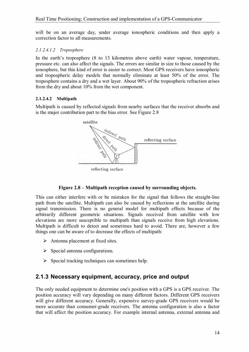
Multipath is caused by reflected signals from nearby surfaces that the receiver absorbs and is the major contribution part to the bias error. See Figure 2.8
Figure 2.8 – Multipath reception caused by surrounding objects.
This can either interfere with or be mistaken for the signal that follows the straight-line path from the satellite. Multipath can also be caused by reflections at the satellite during signal transmission. There is no general model for multipath effects because of the arbitrarily different geometric situations. Signals received from satellite with low elevations are more susceptible to multipath than signals receive from high elevations. Multipath is difficult to detect and sometimes hard to avoid. There are, however a few things one can be aware of to decrease the effects of multipath:
Antenna placement at fixed sites.
Special antenna configurations.
Special tracking techniques can sometimes help.
2.1.3 Necessary equipment, accuracy, price and output
The only needed equipment to determine one's position with a GPS is a GPS receiver. The position accuracy will vary depending on many different factors. Different GPS receivers will give different accuracy. Generally, expensive survey-grade GPS receivers would be more accurate than consumer-grade receivers. The antenna configuration is also a factor that will affect the position accuracy. For example internal antenna, external antenna and
Real Time Positioning; Construction and implementation of a GPS-Communicator
15
antenna position will affect the accuracy. Antenna position is important due to surrounding objects that may block reception of the satellite signal and also cause multipath reception.
Other things that might affect the accuracy are the earlier mentioned bias errors and satellite constellation status. Dilution of precision (DOP) is the mathematical representation of the quality of GPS data being received from satellites. DOP is mainly controlled by the number of visible satellites and their relative positions in the sky (constellation status). The most commonly used dilution of precision is position dilution of precision (PDOP), which is the combination of horizontal dilution of precision (HDOP) and vertical dilution of precision (VDOP). A PDOP value of 1 indicates an optimum satellite constellation and high-quality data. The quality of the data decreases as the PDOP value increases. PDOP values of around 8 are considered poor.
The position accuracy with a consumer-grade GPS receiver is today some where between 5 metres and 25 metres (horizontal position accuracy). Though the accuracy is often within a radius of ten metres (95% confidence interval) with a consumer-grade GPS.
A receiver costs from 3 000 SEK and upwards depending on the quality and brand. Although the low price does not necessarily mean that the accuracy is poor.
The output from the GPS is the NMEA 0183 protocol that is a worldwide standard. Read more about NMEA in Chapter 4 NMEA 0183 protocol
2.1.4 Future of the GPS system
There will be more frequencies in the future, both civilian and military. These frequencies will be separated from each other. The benefits of this system will be better accuracy, for example with two frequencies and DGPS correction the accuracy will be approximately 30 centimetres. This system requires new GPS receivers and will hopefully be in operation in about five years from the year this is written.

Real Time Positioning; Construction and implementation of a GPS-Communicator
16
2.2 Differential GPS
Differential GPS (DGPS) is a system that depends on at least two GPS receivers, at least one stationary receiver and another one that is mobile. The mobile receiver is the one that actually is making position measurements for the end user. The stationary receiver is, on the other hand, the key in the system. It receives signals from all GPS satellites that are visible from the station and performs position measurements on those signals. Correction data for each satellite can then be calculated, hence the reference station’s exact location is known. The calculated correction data are then broadcast on a data link to the end users GPS receiver. The mobile GPS receiver can, with help from the correction data, improve the accuracy of the measured position.
Figure 2.9 - Overview of the DGPS system.
As mentioned earlier, GPS receivers use timing signals from at least four satellites to establish a 3D position and three for a 2D position. Each of those timing signals is going to have some errors and delays. These errors and delays can vary a lot depending on the situation, for example the atmosphere and clock bias etc. cause the inaccuracy in the GPS position measurements. The errors and delays can partly be corrected with the use of the reference station However the reference station cannot correct all kind of errors. Errors contributed from for example multipath signals cannot be corrected, hence the nearby surroundings cause this kind of error which cannot be predicted by the reference station.
There is more than one possible way to use a reference point to correct the position. The most basic and by far the most ineffective way is to calculate the difference in the measured position and the known reference point.
knownmeasured LatitudeLatitudeLatitude −=∆
knownmeasured LongitudeLongitudeLongitude −=∆
knownmeasured AltitudeAltitudeAltitude −=∆
Real Time Positioning; Construction and implementation of a GPS-Communicator
17
The deltas are then subtracted from the measured position given by the mobile GPS receiver to correct the position. This is of course not a good solution. The most obvious reason for that is that the mobile receiver and reference station might not be seeing the same satellites. Hence the contributed errors are not the same for each satellite. This method would have worked better if all the satellites, used in the measurement of the position had been the same both at the stationary- and mobile receiver. There are several reasons to why different satellites might be seen at nearby locations.
The receiver criterion for selecting satellites might differ.
Terrain or earth’s curvature might block a satellite with low elevation angle for users or reference station.
The user receiver might employ an all-in-view strategy, wherein all visible satellites are used to determine position.
Satellites available at user location might differ from those available at reference location.
A better way to calculate correction data is to measure the error in the pseudorange to each satellite. The signals to two different receivers on earth, located at a distance of a few kilometres apart, will have a very small angle between them. One can almost assume that the signals are parallel. With this assumption one will realise that the received signal from one satellite will suffer from almost the same errors and delays at both receiving points. As a reminder, errors that have their origin from atmospheric disturbance, clock bias can partly be corrected with the help from the reference station. Multipath errors will however not be the same at the different locations and cannot be corrected with the help from the reference station.
The accurate position where the stationary reference receiver is located and the true distance to the satellites is known, hence the satellite sends its almanac. This means that it is possible to calculate how long time it should take for the signal to arrive. This calculated time is then compared with the actual time for the signal to arrive, giving an error correction time factor. This factor can be used to correct the pseudorange.
The GPS corrects the pseudorange to the satellite as:
( )factorcorrectionmeasured ttcepseudorangCorrected −⋅=
Where
factorcorretiontimetarrivetosignalthefortimemeasuredt
lightofspeedc
factorcorrection
measured
==
=
The mobile receivers are served with this correction data on a continuous basis through a data link. The correction data are sent out on the data link as a broadcast message. The reference station cannot know which satellites that one specific mobile GPS receiver sees. It therefore sends out correction data for all satellites in view. In this way it increases the chance for the mobile receiver to get correction data for all those satellites that it sees. The mobile receiver can then make a choice and pick up information for those satellites it uses for the measurement. The receiver adds these corrections as shown above to improve the pseudorange before the actual calculation of the position is made.
The correction data are sent out in a standard format called RTCM 104. The messages have a structure similar to the GPS-message format. It has the same word length of 30 bits. One

Real Time Positioning; Construction and implementation of a GPS-Communicator
18
big difference though is that the length of the message varies in the RTCM 104 standard. There can also be up to 64 different types of messages in RTCM 104. Each message always starts with two words partly telling which type of message it is and how long it is (how many words that follow). Within the two words, one will also find information about the reference stations ID-number and health status. The health status is indicated with three bits that lead to eight different conditions. Two of the conditions are standardised and tell that the reference station is not working or that the transmission is not monitored. The bit pattern for these conditions is “111” and “110” respectively. The remaining six conditions are left open for the providers to decide their meaning.
The 64 different types of messages are numbered from Type1 to Type64. Only 26 of them are defined. These defined messages can either be fixed or tentative, retired or reserved. The ones with a fixed form are considered to be in their final form and need not be changed. The tentatively messages are still in an experimental phase and might need some changes. The retired messages are no longer in use and the remaining messages are reserved for future use.
The two most commonly used message types are Type1 and Type9, which both are in a fixed form. The Type1-message “Differential GPS Corrections” contains correction data to all visible satellites in view at the reference station. The Type9-message “Partial Satellite Set Differential Corrections” serves the same purpose as the Type1 message. The difference is that it only contains information of a selected part of all satellites in view. The reason as to why this shorter message type exists is because of the shortness. This means that one does not need to wait for the entire Type1-message to arrive if only interested in corrections for a few satellites.
2.2.1 Typical Equipment
The following picture shows the block structure of the reference station equipment and the mobile equipment. As an end user one must have a GPS receiver that is prepared to receive and handle correction data sent out by the reference station. To do this one will also need a DGPS receiver that is capable of receiving the correction data sent out by the reference stations or DGPS provider.

Real Time Positioning; Construction and implementation of a GPS-Communicator
19
Figure 2.10 – Mobile equipment block structure.
Figure 2.11 – The reference station equipment block structure.
2.2.2 Economic aspects
The economic aspect of a DGPS system varies, depending on which provider one chooses. Some of the providers charge per licence and time interval. For example one can subscribe to a service for a year. The user will then have a fixed price as an annual fee. There will be no other fees added to this. One can also in some cases subscribe for more occasional and shorter periods if a longer subscription is of no interest.
Other providers do not charge for the service at all. They are often run by the government as a public service. The Swedish Maritime Administration, which provides a DGPS-service in Sweden, is an example of this. The only cost will be the cost of the needed equipment.
Real Time Positioning; Construction and implementation of a GPS-Communicator
20
Another economic aspect is of course the cost of the necessary equipment needed. As mentioned earlier, one must have a GPS-receiver that can handle DGPS-correction data. The receiver also must be capable of receiveing the actual correction data. This equipment is dependent on the provider and must correspond to the system used. This equipment will thereby also vary in cost and appearance depending on the provider.
2.2.3 RTK GPS
GPS-receivers for ordinary consumers are quite common today due to low prices and simple use. There are also other types of GPS-receivers that are more sophisticated available on the market. One type of receiver is called carrier phase GPS, an often used term for these receivers is Real Time Kinematics (RTK).
A RTK GPS uses the PRN code, as an ordinary GPS-receiver does, to find a fairly accurate position and then measure the phase of the carrier frequency. The phase is then compared with the phase of a generated carrier inside the receiver to determine a more accurate position. This technique is quite dependent on reduced errors to be accurate, hence the wavelength is quite small. To obtain any gain from this technique one must use correction data from a reference station.
2.2.3.1 Overview Relation between wavelength (λ), frequency (f) and the speed of light (c) in vacuum is:
λcf =
The frequency f defines the number of cycles the phase ϕ changes in one second. The relation between frequency and phase is:
∫ ⋅=⇒⋅=⇒= dtfdtfddtdf ϕϕϕ
An expression for the phase difference between two points will then be:
( ) { } [ ] ( )00 0
0
constant )( ttftffdtftt tt
t
t
−=⋅==⋅=− ∫ϕϕ
Now assume ( ) 00 =tϕ and 00 =t . This gives:
( ) tft ⋅=ϕ
The phase can in this way be calculated at different instants of time at a certain point in space, if the assumption above is valid.
The phase Sϕ of the received carrier at the time t will be the same as it was at the satellite at the time tt ∆− + Sdt , where t∆ is the travel time c
ρ and Sdt is the clock error in the satellite clock. (p is the code measured distance).

Real Time Positioning; Construction and implementation of a GPS-Communicator
21
( ) ( )( ) SScSSScSS dtfftfdttft +−=+−= ρρϕ
The phase Rϕ for the phase carrier generated by the receiver is:
( ) ( )RRR dttft +=ϕ
Where Rdt is the clock error in the receiver.
This gives the phase difference SRϕ
( ) ( ) ( ){ } ( )RScRS
RRRSScSSRSSR
dtdtfffff
dtftfdtfftfttt
−+−====
=−−+−=−=ρ
ρϕϕϕ
2.2.3.1.1 Measurable phase difference
Assume that the receiver is turned on at the time t0. Only the phase difference within a cycle between the received phase and the phase generated by the receiver can be measured. The number of whole cycles N it takes for the signal to arrive at the receiver will be unknown and must be determined separately. The measurable phase difference denotes
ttSR 0
ϕ∆ .∆ϕ1
Figure 2.12 – Shows the relation between the phase differences SRϕ , the measurable
phase difference ttSR 0
ϕ∆ and N.
( ) Nt ttSRSR +∆=0
ϕϕ
Initiating ttSR 0
ϕ∆−=Φ gives:
( ) NdtdtffN RScttSR +−−=+−=Φ ρϕ0

Real Time Positioning; Construction and implementation of a GPS-Communicator
22
Insert λcf = gives:
( ) Ndtdt RSc +−−=Φ λλ
ρ
Φ is given with the unit cycles. Multiplying the expression with the wavelength λ gives the unit metres and this will be the pseudorange R to the satellite
( ) NdtdtcR RS λρ +−−=
Real Time Positioning; Construction and implementation of a GPS-Communicator
23
2.2.4 Real Time Services
We will here enumerate available DGPS-services in Sweden. Information on prices, accuracy, coverage, needed equipment and name of the service will also be pointed out.
There are, at this time, a number of companies that can offer real time services with respect to DGPS.
2.2.4.1 Cartesia Cartesia offers two DGPS services: EPOS and Ciceron. The correction data are taken from SWEPOS. SWEPOS is a national network of permanent reference stations provided and served by the Swedish Land Survey.
2.2.4.1.1.1 EPOS
EPOS is one of the services offered by Cartecia. It broadcasts correction data through the national and local radio network. The coverage is almost nation-wide because of the carrier used. The data are broadcast in a sub-channel called RDS (Radio Data System) on the FM programme channels P3 and P4.
There are several other providers in countries around Europe that use the same carrier. The countries in Europe that offer DGPS through RDS are Belgium, Denmark, Finland, Great Britain, Holland, Hungary, Italy, Luxembourg, Slovakia, Switzerland and Turkey. France has evaluated the system and will soon have a fully operating system. Austria, Germany, Norway, Poland, Portugal and Spain are still evaluating this system and have not yet decided whether or not they will go ahead with it. There are also a few countries outside Europe that offer the same service with the same technique. One can also find the service in Australia, Canada, Israel, Singapore, Taiwan and in the United States.
Necessary equipment:
A GPS-receiver supporting corrections via DGPS data An EPOS-receiver (for example AZTEK RXMAR2) with an antenna.
An EPOS Premium Subscription. Price / Subscriptions / Accuracy:
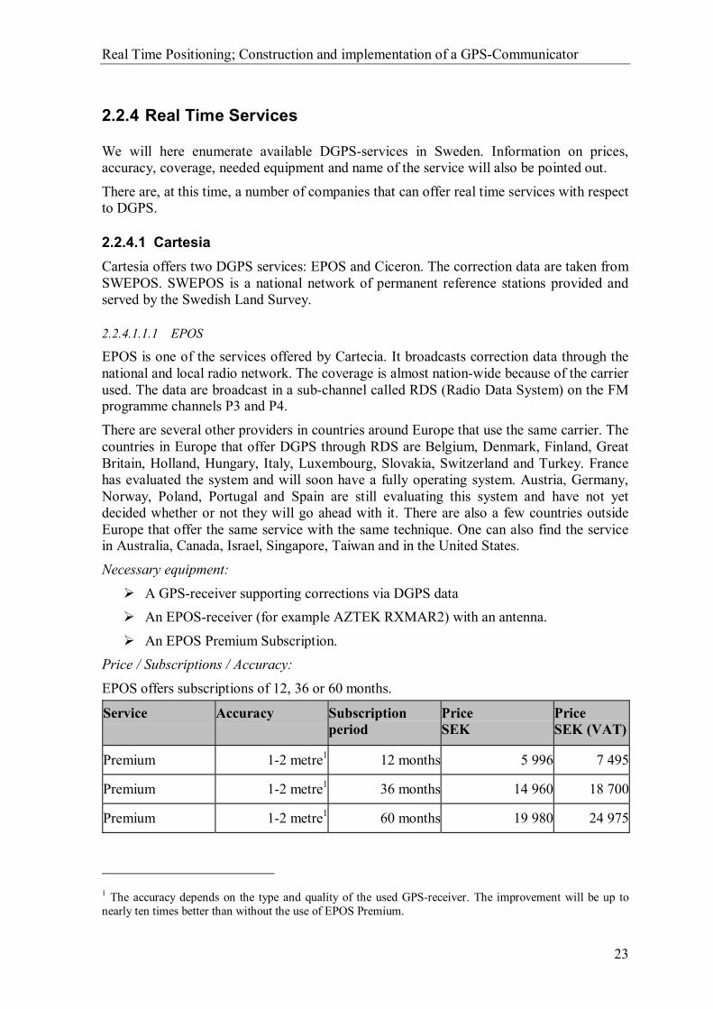
EPOS offers subscriptions of 12, 36 or 60 months.
Service Accuracy Subscription period
Price SEK
Price SEK (VAT)
Premium 1-2 metre1 12 months 5 996 7 495
Premium 1-2 metre1 36 months 14 960 18 700
Premium 1-2 metre1 60 months 19 980 24 975
1 The accuracy depends on the type and quality of the used GPS-receiver. The improvement will be up to nearly ten times better than without the use of EPOS Premium.
Real Time Positioning; Construction and implementation of a GPS-Communicator
24
Coverage: The coverage is quite large because of the carrier used. The FM radio network is often very widely built out. One can for example receive radio signals in the FM-band in 99.8 percent of the Swedish territory. The needed equipment can also be used in other countries that offer the same kind of service. The only thing one must arrange is a subscription corresponding to EPOS service in the specific country.
2.2.4.1.2 Ciceron
Ciceron is one of the services offered by Cartesia. The service delivers correction data to RTK GPS-receivers. The data are broadcast through the FM radio network in a sub channel called DARC (Digital Audio Radio Communication), which is almost equal to RDS but with wider bandwidth.
Necessary equipment:
A GPS/RTK-receiver that supports RTCM 104 v2.2. A Ciceron-receiver (can be borrowed from Ciceron).
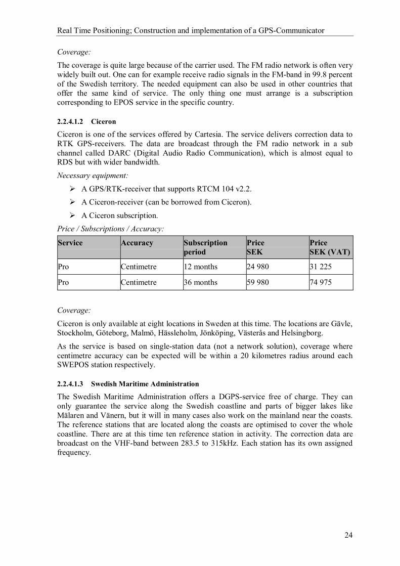
A Ciceron subscription. Price / Subscriptions / Accuracy:
Service Accuracy Subscription period
Price SEK
Price SEK (VAT)
Pro Centimetre 12 months 24 980 31 225
Pro Centimetre 36 months 59 980 74 975
Coverage:
Ciceron is only available at eight locations in Sweden at this time. The locations are Gävle, Stockholm, Göteborg, Malmö, Hässleholm, Jönköping, Västerås and Helsingborg.
As the service is based on single-station data (not a network solution), coverage where centimetre accuracy can be expected will be within a 20 kilometres radius around each SWEPOS station respectively.
2.2.4.1.3 Swedish Maritime Administration
The Swedish Maritime Administration offers a DGPS-service free of charge. They can only guarantee the service along the Swedish coastline and parts of bigger lakes like Mälaren and Vänern, but it will in many cases also work on the mainland near the coasts. The reference stations that are located along the coasts are optimised to cover the whole coastline. There are at this time ten reference station in activity. The correction data are broadcast on the VHF-band between 283.5 to 315kHz. Each station has its own assigned frequency.

Real Time Positioning; Construction and implementation of a GPS-Communicator
25
Necessary equipment:
A GPS-receiver supporting corrections via DGPS data (for example Trimble AgGPS122)2
A DGPS-receiver capable to receive correction data on the VHF-band (for example Trimble AgGPS122)
Price / Subscriptions / Accuracy: The obtainable accuracy with this system varies from one to ten metres depending on the used equipment, the availability of the correction data and the provider. If provided with correction data for all satellites, used in measurement, the accuracy will be within one metre 95 % of the time.
Service Accuracy Subscription period
Price SEK
Price SEK (VAT)
SMA 1-(10) Metre None Free Free
Coverage: Along the Swedish coastline and parts of the lakes Mälaren and Vänern.
2.2.4.1.4 MobiPos
MobiPos is a DGPS service offered by the Swedish company Generic Mobile Systems. DGPS data are delivered by using data cast on a data channel of the Swedish Broadcasting Corporation’s FM P3. The channel called DARC (Digital Audio Radio Communication) is developed according to an international standard.
2.2.4.2 DGPS via GEO GEO satellites (GEO-stationary satellites) can be used to provide DGPS corrections over large areas of the world. The GEO satellites are placed in orbit over the equator and with an orbital period of one sidereal day, which is approximately 4 minutes shorter than a solar day (24h). Due to this orbital period and satellite positioning the satellite will appear in the same place in the sky when observed from the same point on the earth (at different times).
2.2.4.2.1 OmniSTAR
OmniSTAR is a service provide by Fugro. The service uses GEO satellites for distributing DGPS data and local reference stations (for example in Sweden OmniSTAR uses SWEPOS reference stations). Totally 86 reference stations are used and this gives a system that covers 90% of the world. However it can be difficult to receive the DGPS corrections from the GEO satellites near the poles due to the low elevation angels. OmniSTAR claims position accuracy to be 1-2.5 metres.
2 Integrated GPS receiver and a radio Beacon receiver.

Real Time Positioning; Construction and implementation of a GPS-Communicator
26
Figure 2.13 – OmniSTAR coverage map.
With this accuracy one will have a number of choices for the area of usage. For example this service can be used on seas far from coasts or in the wilderness (where no land-based stations that provide DGPS corrections are available).
2.2.4.2.2 WAAS
WAAS (Wide Area Augmentation System) consists of approximately 25 ground reference stations positioned across the United States. Therefore the DGPS corrections provided by WAAS are only useful to users in (or around) the United States. WAAS satellite covers North America and South America, though at the moment there are no reference stations available in South America for the WAAS system. It is possible to obtain accuracy beneath 3 metres with the WAAS system.
2.2.4.2.3 Others GEO DGPS
Europe has the project EGNOS which is a joint project of ESA, the European Commission and Eurocontrol, the European Organisation for the Safety of Air Navigation. In Asia there is the Japanese Multi-Functional Satellite Augmentation System (MSAS).
2.2.5 Post processing
SWEPOS provides GPS data for post-processing. These data are in RINEX (Receiver INdependent EXchange) format. The format is independent of receiver type/brand. RINEX can be seen as a standard transfer format for GPS data. Post processing has several disadvantages, to mention some: post-processing takes time, one cannot observe possible errors (thus one has to redo measurements).
2.2.6 Network RTK
Network RTK uses a network of stationary reference stations to calculate correction data. These stations are placed at 60-80 kilometres distance from each other. Network RTK also provides an ionosphere model to correct the ionosphere effect.
Real Time Positioning; Construction and implementation of a GPS-Communicator
27
In Sweden SWEPOS together with local actors, has done or still does research on Network RTK in different parts of the country. The projects are: NeW-RTK, Väst-RTK (West coast and western part of Sweden), Skan-RTK (Southern Sweden, Skåne) and Position Stockholm-Mälaren. SWEPOS today has reference stations all over Sweden, which are placed approximately 200 kilometres from each other. These stations together with new stations are used in these projects.

Real Time Positioning; Construction and implementation of a GPS-Communicator
28
2.3 AGPS
The Assisted GPS (AGPS) system takes advantage of different methods to determine position. AGPS uses GMS positioning techniques and GPS positioning to determine a position.
AGPS improves the performance of the GPS receiver unit by providing it with data that otherwise had to be downloaded from the satellites. Using this technique time to first fix (TTFF) can be shortened. Conventional GPS receivers need to search the entire frequency/code space to get the first fix (cold start). Thus position can be determined faster with AGPS technology.
We have unfortunately not been able to obtain information about the way position data are delivered to the end user. It is quite likely that the AGPS unit can deliver position data through the NMEA protocol but this is something that we have not had confirmed.
2.3.1 System structure
The system contains a wireless handset (mobile phone) with a partial GPS receiver, an AGPS server with a reference GPS receiver that sees the same satellites as the handset and a wireless infrastructure containing base stations and mobile switching centre (MSC).
The network can predict the GPS signal that the handset will receive and send this information to the handset. This will shorten the TTFF from minutes to a second or less and reduce the search space size. An AGPS receiver is also able to detect and demodulate weaker signals than conventional GPS receivers. AGPS receivers can use scaled-down GPS receivers because the network performs the location calculations.
Figure 2.14 – Overview of the AGPS system.
2.3.2 Accuracy
AGPS achieves about 50 metres accuracy for indoor use and about 15 metres for outdoor use.

Real Time Positioning; Construction and implementation of a GPS-Communicator
29
2.4 Mobile Positioning System
The position of a GSM mobile phone can be determined using information from the GSM radio network. The accuracy with which the location can be determined depends on the network cell3 plan and the status of the phone. The best accuracy will be obtained in cities and other places were the size of the cells is small. Cells covering the countryside are larger and will give a poorer accuracy. One talks about an accuracy of 150 metres inside cities and 1.5 kilometres in the countryside.
There are several methods to use for positioning a mobile phone, some of them are described below. Unfortunately no worldwide standard exists for how the position is delivered to the end user. The position is often delivered through an SMS and not all mobile phones have the availability to extract the SMS to a connected unit. The mobile phone must support this if the position is to be imported into GEOSECMA.
2.4.1 Cell Global Identity-Timing Advance
CGI-TA is a combination of two positioning methods used to determine the position of a mobile phone. Not so surprisingly the methods are CGI and TA.
Cell Global Identity (CGI) uses the identity of each cell to position the mobile phone. Hence one knows where the base station is located and one knows which area it covers. But with the identity of the cell the position will only known in a quite wide area. One will roughly know the location inside a big circle covered by the base station, see Figure 2.15.
Figure 2.15 – CGI-TA method, the mobile is located somewhere in the gray circle.
Time Advance (TA), which is an integrated parameter in the GSM-standard, basically tells how long time it takes for the signal to arrive to the base station. TA is normally used in the GSM-system to determine how much in advance the mobile phone must transmit in an uplink burst in order to be received at the base station at the corresponding time slot. This parameter is not seen by the daily user, instead it is a parameter only used inside the system.
The time precision of TA is however not good enough to calculate the exact distance from the base station to the mobile phone. Combining TA and CGI makes it possible to narrow
3 Area covered by the base station

Real Time Positioning; Construction and implementation of a GPS-Communicator
30
down the radius if the circle of which one is located inside and thereby also gives a better accuracy of the position than without TA.
The accuracy depends on the size of the cell. Smaller cells give of course better accuracy than bigger cells.
One big advantage of CGI – TA is that no extra equipment is needed. It works with all GSM-phones and the base station needs no hardware rebuilding. The only thing needed is some changes in the software at the base stations. This makes the method cheap and easy to implement and is the reason that the method is used by most providers.
2.4.2 Time Of Arrival
This technique measures time of arrival of signals from the mobile phone at different base stations. The position is determined by calculating the intersection of the range circles, see Figure 2.16. The radii of the circles are given by the absolute time for the signal to arrive.
Figure 2.16 – Illustration of the TOA method.
This requires that at least three different base stations receive signals from the same mobile phone if a unique fixed position is desirable. Two base stations will only give an ambiguous fix. Further requirements are that the base stations must be able to force the mobile phone to make handovers. The reason for this is to obtain more than one range circle. The base stations must also be able to share time of arrival information among themselves.
TOA involves major changes at the base stations because of the requirements mentioned above. Both the hardware and the software must be changed, which results in heavy expenses. No changes must, on the other hand be made in the mobile phones.
2.4.3 Time Difference of Arrival
This technique determines the position based on triangulation. Instead of measuring the absolute time of arrival like TOA does, TDOA measures the difference of time of arrival between different base stations. The time difference is converted to a constant distance difference between two base stations. This defines a hyperbolic curve, see Figure 2.17, indicating possible locations of the mobile phone. If a second base station is used to define yet another hyperbolic curve, it is possible to calculate the intersection between the two curves and find a unique position.

Real Time Positioning; Construction and implementation of a GPS-Communicator
31
The requirements are almost the same as for TOA. At least three base stations are needed and they must be able to communicate among themselves. They must also have synchronised time to be able to calculate the difference of time of arrival.
Even this method requires major changes in the base stations leading to heavy expenses.
Figure 2.17 – Shows the hyperbolic curves used to calculate the position with TDOA.
2.4.4 Enhanced Observed Time Difference
In Enhanced Observed Time Difference (E-OTD) the mobile phone uses the surrounding base stations to measure the time difference between the earliest arriving signal components from the different base stations. These measurements are sent by the mobile phone to a mobile location centre (MLC). The MLC performs the location calculations through triangulation, hence the exact locations of the base stations are known. E-OTD also requires synchronisation between base stations, which is achieved through measuring timing differences with a similar technique as used with the mobile phone. These real time differences (RTDs) are then sent to the MLC.
Disadvantages of this technique are the need of new software in the mobile phone and additional software and hardware at the base stations.

Real Time Positioning; Construction and implementation of a GPS-Communicator
32
2.4.5 Angle Of Arrival
The AOA technique measures the phase difference in arriving signals from the mobile phone at the base station. This is possible by using an antenna array at the base station, which consists of many antenna elements placed less than a wavelength away from each other. These antenna elements can be used to determine the phase different on the received signal. The phase difference makes it possible to calculate the angle θ (See Figure 2.18) of the mobile phone relative to the base station. The intersection between two or more base stations “angle lines” provide the mobile phone’s location. Thus using only two base stations might be a problem if the mobile phone is located somewhere on a line between the two base stations. This technique can be used with existing mobile phones, although an antenna array has to be installed at each base station.
.
Figure 2.18 – AOA uses angle lines to determine the mobiles position
Real Time Positioning; Construction and implementation of a GPS-Communicator
33
3 Communication links
3.1 Mobile Internet Connection
3.1.1 GSM
GSM is a circuit-switched system and was designed for speech calls. Therefore the uplink and downlink channels need to be allocated for a user for the entire call period. In other words, to transfer data via GSM a connection has to be established and the user needs to constantly be connected during data transfers. Using either a GSM phone with a built-in modem or a standalone GSM modem makes it possible to establish such a connection. The connection establishment time to a standard modem (analogue) in a GSM system is approximately 20-25 seconds. By connecting to an ISDN modem (this system is digital) this time can be shortened to approximately five seconds. A subscription from the operator that supports data transfers is also needed for GSM communication. It is possible to achieve a maximum transfer rate of 9.6 kbit/s with a GSM connection.
To connect to the Internet using a GSM connection an ISP subscription is needed in most cases. It is also possible to use dialup connections at local offices, if available. In our case, with GEOSECMA, this might be a good idea to guarantee bandwidth and safety (when using ISP it is possible that someone can sniff the traffic).
3.1.2 HSCSD
High Speed Circuit Switched Data (HSCSD) is as the GSM circuit-switched but it has a different coding scheme with less error protection capabilities. HSCSD has the possibility to fallback to lower transfer rates and get better error protection. The maximum transfer rate per timeslot with HSCSD is 14.4 kbit/s (some systems supports only 9.6 kbit/s per timeslot). A user can use a maximum of four timeslots. It is also possible to define how many timeslots should be used for downlink and uplink. For example one might use 3+1 that means three timeslots for downlink and one for uplink. This combination gives the highest possible downlink speed with HSCSD, which is 43.2 kbit/s (14.4 kbit/s *3).
This chapter will describe different communication links that might be used to establish a connection with the field application. The communication links descried here are the ones we think are most suitable today or in the near future. Of course there are other possible techniques that might be used such as Wireless LAN (802.11b) or satellite modem using ORBCOMM satellite network (global coverage). These systems/techniques will however not be described here. The following references are of interest for this chapter: [20-25, 34-36].

Real Time Positioning; Construction and implementation of a GPS-Communicator
34
The cost for HSCSD for two Swedish providers:
Provider Service Subscription fee
Monthly fee
Minute fee
Max transfer rate
Vodafone Vodafone Data 43 K
(375) (320) + 31.25 2.48 43.2 kbit/s
Telia Mobiltel företag 250 175 3 28.8 kbit/s
All fees and transfer rates are topical from 2002-05-17 and are given in SEK including VAT. The fees within parenthesis are fees for base subscriptions that are needed for using the service.
3.1.3 GPRS
GPRS stands for General Packet Radio Service and the technique is packed-switched instead circuit-switched as for GSM. This means that the data stream is divided into small packages that are routed through the network. To make this possible each package contains a destination address. This type of connection between a sender and a receiver is called connectionless, unlike the circuit-switched system where it is called dedicated. With a connectionless connection the user can be “connected” all the time without taking up any bandwidth. Bandwidth is only used when the user sends or receives data. With a dedicated connection the user uses bandwidth even if not sending or receiving any data. When using dedicated connection the user pays for the whole connection time even if no data are sent or received, with GPRS the user only pays for the amount of data transferred. Some providers do charge for connections that last more then 24 hours.
The transfer rate is higher with GPRS than with GSM (CSD). Using four different channel coding schemes (CS) does this. CS1 is 9.05 kbit/s per timeslot, CS2 is 13.4 kbit/s per timeslot, CS3 is 15.6 kbit/s per timeslot and CS4 is 21.4 kbit/s per timeslot. Today’s systems only use CS1 or CS2 with a maximum of four timeslots. This gives a maximum transfer rate of 36.2 kbit/s (9.05 kbit/s * 4) for C1 and 53.6 kbit/s (13.4 kbit/s * 4) for CS2. As for HSCSD it is possible to specify how many timeslots that should be used for downlink and uplink (hardware/software dependent). The transfer rate can vary from transfer to transfer, the reason for this is that the system is designed for speech and speech data have priority in the system. GPRS also reduces the time it takes to establish a connection.
With GPRS the user do not need a subscription at an ISP for Internet connection. The Internet connection is “built in” with GPRS and the user gets the Internet connection through the provider for the GPRS service. GPRS supports Internet Protocol (IP) and X.25 protocol that makes the connection to the Internet easier.

Real Time Positioning; Construction and implementation of a GPS-Communicator
35
The cost for GPRS for two Swedish providers:
Provider Service Subscription fee
Monthly fee
Fee per MB
Include MB/month
Max transfer rate
Vodafone Vodafone Data GPRS
(250) (319) + 65 12.50 2.0 53.6 kbit/s
Telia Telia Mobile OnLine
(250)+100 300 18.00 25.0 36.2 kbit/s
All fees and transfer rates are topical from 2002-05-17 and are given in SEK including VAT. The fees within parenthesis are fees for subscriptions that are needed for using the service.
3.1.4 UMTS
Universal Mobile Telecommunications System (UMTS) is intended to provide global mobility (global radio coverage and worldwide roaming) with a wide range of services including telephony, Internet, messaging, paging and broadband data. The global radio coverage is achieved with satellites covering the whole world. The system will offer different services, for example telephony service (like speech and SMS), and bearer service. The bearer service provides information transfers between access points. Both connection less and connection oriented services are offered for Point-to-Point and Point-to-Multipoint communication. Bearer service will have different transfer speeds depending on where the user is located. Indoors and in very small cells outdoor the maximum transfer speed is 2048 kbits/s (ideal conditions), outdoors in urban areas 384 kbit/s as best and for satellite and outdoors in the countryside the maximum transfer speed is 144 kbit/s.
3.1.4.1 Classes UMTS network services provide different classes for four types of traffic.
Conversational class (voice, video telephony).
Streaming class (multimedia, video on demand). Interactive class (web browsing, database access).
Background class (email, SMS).
3.1.4.2 Network architecture The UMTS network consists of three interacting domains: the radio access network (UTRAN), the core network (CN) and user equipment (UE). The UTRAN consists of a mobile station (MS), a base station (BS) and the radio interface between these. The core network consists of nodes and connecting lines that are used to connect the base stations and provide gateways to other networks (the Internet for example). The core network is an evolution of the present GSM-core network and will use Asynchronous Transfer Mode (ATM) for transmission. Therefore there will be a common core network (GSM and UMTS uses the same) and two independent radio access networks. The radio access network in UMTS uses lager bandwidth (5 MHz) then GSM (200 kHz) and a different

Real Time Positioning; Construction and implementation of a GPS-Communicator
36
access method, Wide band Code Division Multiple Access (WCDMA) is used. WCDMA has two basic modes of operation: Time Division Duplex (TDD) and Frequency Division Duplex (FDD). FDD operation mode is assigned for macro- and micro cells while TDD is assigned for pico cells.
3.1.4.3 Spectrum UMTS uses a spectrum between 1900 MHz to 2025 MHz and 2110 MHz to 2200 MHz. For the satellite service a sub-band is reserved in the UMTS spectrum, for uplink 1980 MHz to 2010 MHz and for downlink 2170 MHz to 2200 MHz.
3.2 Mobitex (radio modem)
Mobitex is a narrowband data-only network developed by Ericsson. The network consists of base stations (which cover a cell) that provide wireless access for the mobile users in the network. The base stations are connected with each other using fixed links. The system uses packet switching (based on open international standard) to transfer data in the network.
3.2.1 Narrowband
Mobitex uses narrowband radio technology and the communication channels in the network have a bandwidth of 12.5 kHz. Mobitex therefore does not require such a wide radio spectrum as for example GSM (CSD) that has a bandwidth of 30 kHz. Mobitex networks can operate on different frequencies, the most common are these four: 80 MHz, 400 MHz, 800 MHz or 900 MHz.
3.2.2 Dedicated data
Mobitex was designed to carry data traffic and therefore the data transfers cannot be blocked by voice calls. For example about 400 Mobitex users can share a single communications channel without any deterioration in service.
3.2.3 Packet-switched system
The system is packet switched which means that the data stream is divided into small packages that can be sent individually through the network. Each packet contains a destination address and can be routed dynamically through the network, therefore no dedicated connection is needed.
There are 30 Mobitex networks around the world in 23 different countries, however some networks are only for private use. In Sweden there are two public networks, one provided by Telia and one by MOWIC. Telia’s network uses 80 MHz and covers 90% of Sweden’s area.
To connect to a Mobitex network one needs a modem, it can be a mobile one or a stationery modem that is directly connected to a Mobitex exchange (MOX). A subscription from a Mobitex network provider is also needed.
Real Time Positioning; Construction and implementation of a GPS-Communicator
37
3.3 Internal radio modem network
There are many different configuration possibilities with an internal radio modem network, because of the many companies that provide different solutions. For example radio modems use different frequencies, different speeds to communicate and have different transmitter output effect.
A solution with an internal radio modem network requires an internal base station or base stations. The coverage of the network depends on many different factors, to mention some: transmitter output effect, antenna used, antenna placement and frequency. The most common transfer speed today with a radio modem solution is 19.2 kbit/s.
It is hard to show the exact costs for a radio modem network because it depends on which solution one chooses. First of all there is the cost to establish the network, hardware and installation costs (both for mobile users and base station). There might also be a fee for a license to use the radio frequency. The costs for transferring data when the network is established are the operating costs for the system.

Real Time Positioning; Construction and implementation of a GPS-Communicator
38
4 NMEA 0183 protocol
NMEA 0183 is an industry standard from the National Marine Electronics Association that defines an electrical interface and a data protocol for communications between marine instrumentation. The standard defines electrical signal requirements, data transmission protocol, timing and specific sentence formats. The National Marine Electronics Association is an association of manufactures, dealers, educational institutions, distributors and others that are interested in peripheral marine electronics communication between marine instrumentation. The standard is today also used together with non-marine instrumentation, for example to navigate on roads with a GPS receiver.
There are different versions of the NMEA 0183 standard and new standards have been developed, for example there is a NMEA 2000 standard (The network standard for interfacing marine electronics devices).
4.1 NMEA electrical interface
NMEA 0183 devices are designed either as listeners or talkers (some devices can be both). NMEA allows a single talker and several listeners on one circuit. The devices use an asynchronous serial interface to communicate. The most common parameters for the serial interface are:
Baud rate: 4800 bps (NMEA 0183 supports up to 38400 bps) Number of data bits: 8 (bit 7 is 0) Stop bits: 1 (or more) Parity: None Handshake: None
There are however devices that use other baud rates to communicate. For example on many Garmin GPS’s there is a possibility for the user to change the GPS’s baud rate.
The serial interface often follows the EIA RS-232 standard that specifies the signal voltages, signal timing, signal function, a protocol for information exchange, and mechanical connectors.
There are GPS today that only have a single line with 5V CMOS or TTL compatible signal level. Though the standard recommends that the talker output complies with EIA RS-422.
The following chapter will discuss the NMEA 0183 protocol. We will give a few examples of different messages to show the typical structure. Positioning units like GPSand DGPS receivers use this protocol. The following references are of interest for thischapter: [5, 47, 48].

Real Time Positioning; Construction and implementation of a GPS-Communicator
39
4.2 General sentence format
All data transmitted with NMEA is in the form of sentences. Only printable ASCII4 characters are allowed with the exception of CR5 and LF6. The sentences always start with a $ sign and end with <CR><LF>. A sentence may contain up to 80 characters excluding $, CR and LF. There are three basic kinds of sentences: proprietary-, talker- and query sentences (there are 85 different sentences in NMEA 0183 v 3.0).
4.2.1 Talker sentence
A talker sentence starts with a $ followed by two characters (tt) that are the talker identifier. The next three characters are the sentence identifier (sss), followed by a number of data fields (d1, d2, …, dn) separated by commas. If data for a field are not available the commas are still sent but with no spaces between them. An optional checksum is followed after the data fields and then the sentence is ended with CR and LF. The general format for a talker sentence is:
$ttsss,d1,d2, ...,dn,*hh,<CR><LF>
4.2.2 Proprietary sentences
The NMEA standard allows manufactures to define their own sentences. These sentences are called proprietary sentences and start with $P followed by a three letter manufacturer ID. This is followed by data that the manufacture decides, following the general format of the standard sentences.
4.2.3 Query sentence
A query sentence is a sentence used by the listener to request a specific sentence from a talker device. The first two characters after the $ are the talker identifier (tt) of the requester; the next two characters are the talker identifier (ll) of the listener (device being queried). The fifth character is always a Q defining that the message is a query. The next field contains three characters, these are the sentences identifier (sss) for the requested sentence. The general format for a query sentence is:
$ttllQ,sss,<CR><LF>
4 ASCII –American Standard Code for Information Interchange. ASCII code is the numerical representation of a character such as 'a' or '@' or an action of some sort
5 CR – Carriage return
6 LF – Line feed

Real Time Positioning; Construction and implementation of a GPS-Communicator
40
4.3 Talker identifiers
Talker identifiers give information about who the talker is and are specified in the first one or two characters in the sentence $--. One example of talker identifiers is:
GP Global Positioning System (GPS)
4.4 Sentence identifier and formats
The sentence identifier also gives information about sentence type, thus the format of the sentence is then known. The most common sentence identifier is GGA (Global Positioning System Fix Data) and it is transmitted by all GPS’s.
Here follow a few examples of sentence identifiers and their sentence structure.
4.4.1 ALM GPS Almanac Data
The ALM message gives information of the satellites health status and orbital data. The message is not supported by all GPS receivers and is not necessary to the end user if the only required data are the position. The complete contents of the message are shown below.
1 2 3 4 5 6 7 8 9 10 11 12 13 14 15 16 | | | | | | | | | | | | | | | | $--ALM,x.x,x.x,xx,x.x,hh,hhhh,hh,hhhh,hhhh,hhhhhh,hhhhhh,hhhhhh,hhhhhh,hhh,hhh,*hh
1) Total number of messages
2) Message Number 3) Satellite PRN number (01 to 32)
4) GPS Week Number: Date and time in GPS is computed as number of weeks from 6 January 1980 plus number of seconds into the week.
5) SV health, bits 17-24 of each almanac page 6) Eccentricity
7) Almanac Reference Time 8) Inclination Angle
9) Rate of Right Ascension 10) Root of semi-major axis
11) Argument of perigee 12) Longitude of ascension node
13) Mean anomaly 14) F0 Clock Parameter
15) F1 Clock Parameter

Real Time Positioning; Construction and implementation of a GPS-Communicator
41
16) Checksum
4.4.2 BWC Bearing and Distance to Waypoint
Some GPS receivers can handle and create waypoints to make navigation easier. This message can be used to feed another unit connected to the GPS with information about bearing, distance and coordinates to the next waypoint. Note that not all GPS receivers support this message. The complete contents and structure of the message are shown below.
1 2 3 4 5 6 7 8 9 10 11 12 13
| | | | | | | | | | | | | $--BWC,hhmmss.ss,llll.ll,a,yyyyy.yy,a,x.x,T,x.x,M,x.x,N,c--c*hh
1) Time (UTC) 2) Waypoint Latitude
3) N = North, S = South 4) Waypoint Longitude
5) E = East, W = West 6) Bearing, True
7) T = True 8) Bearing, Magnetic
9) M = Magnetic 10) Nautical Miles
11) N = Nautical Miles 12) Waypoint ID
13) Checksum
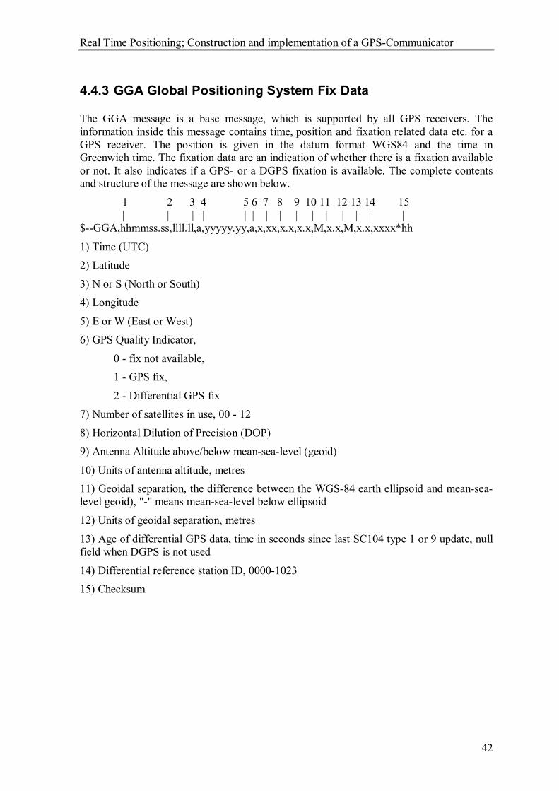
Real Time Positioning; Construction and implementation of a GPS-Communicator
42
4.4.3 GGA Global Positioning System Fix Data
The GGA message is a base message, which is supported by all GPS receivers. The information inside this message contains time, position and fixation related data etc. for a GPS receiver. The position is given in the datum format WGS84 and the time in Greenwich time. The fixation data are an indication of whether there is a fixation available or not. It also indicates if a GPS- or a DGPS fixation is available. The complete contents and structure of the message are shown below.
1 2 3 4 5 6 7 8 9 10 11 12 13 14 15 | | | | | | | | | | | | | | | $--GGA,hhmmss.ss,llll.ll,a,yyyyy.yy,a,x,xx,x.x,x.x,M,x.x,M,x.x,xxxx*hh
1) Time (UTC) 2) Latitude
3) N or S (North or South) 4) Longitude
5) E or W (East or West) 6) GPS Quality Indicator,
0 - fix not available, 1 - GPS fix,
2 - Differential GPS fix 7) Number of satellites in use, 00 - 12
8) Horizontal Dilution of Precision (DOP) 9) Antenna Altitude above/below mean-sea-level (geoid)
10) Units of antenna altitude, metres 11) Geoidal separation, the difference between the WGS-84 earth ellipsoid and mean-sea-level geoid), "-" means mean-sea-level below ellipsoid
12) Units of geoidal separation, metres
13) Age of differential GPS data, time in seconds since last SC104 type 1 or 9 update, null field when DGPS is not used
14) Differential reference station ID, 0000-1023 15) Checksum
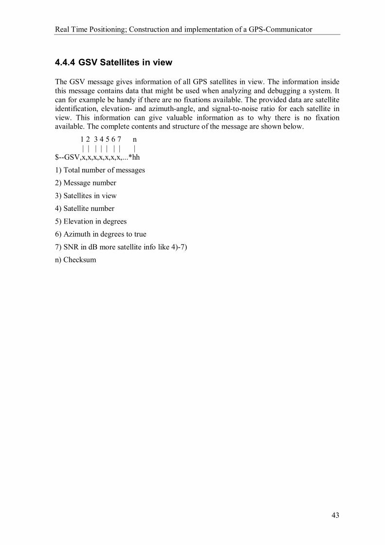
Real Time Positioning; Construction and implementation of a GPS-Communicator
43
4.4.4 GSV Satellites in view
The GSV message gives information of all GPS satellites in view. The information inside this message contains data that might be used when analyzing and debugging a system. It can for example be handy if there are no fixations available. The provided data are satellite identification, elevation- and azimuth-angle, and signal-to-noise ratio for each satellite in view. This information can give valuable information as to why there is no fixation available. The complete contents and structure of the message are shown below.
1 2 3 4 5 6 7 n | | | | | | | | $--GSV,x,x,x,x,x,x,x,...*hh
1) Total number of messages 2) Message number
3) Satellites in view 4) Satellite number
5) Elevation in degrees 6) Azimuth in degrees to true
7) SNR in dB more satellite info like 4)-7) n) Checksum
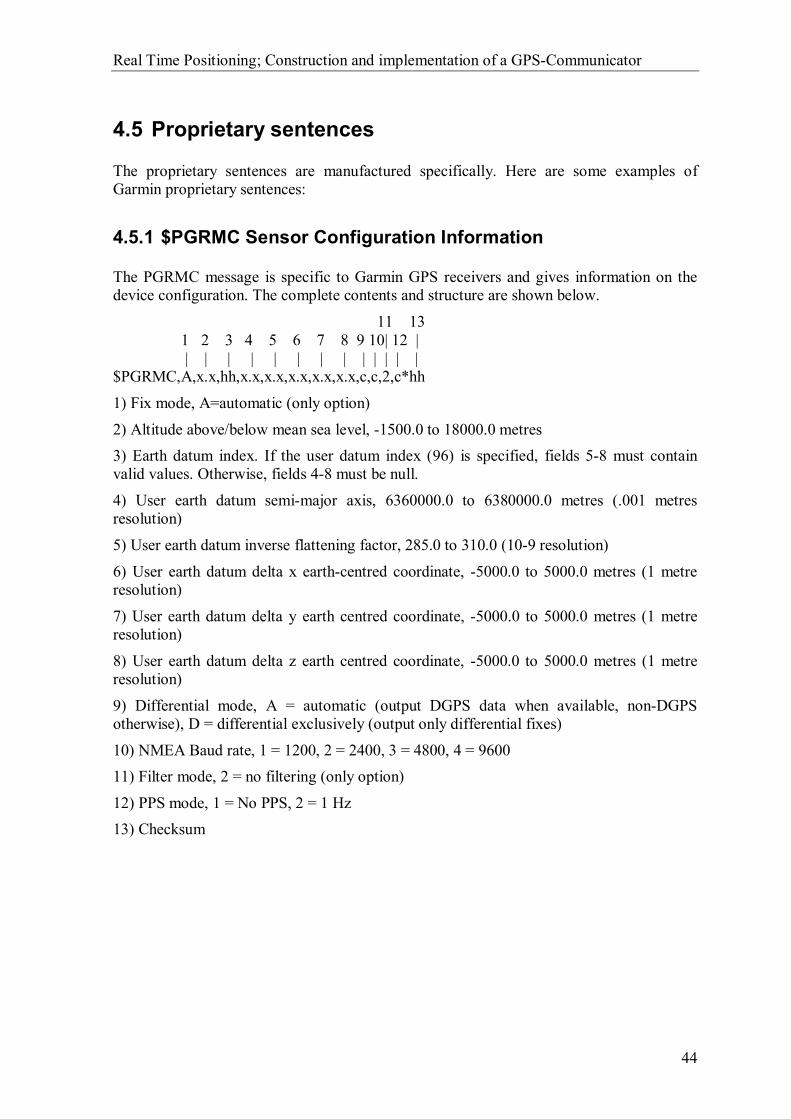
Real Time Positioning; Construction and implementation of a GPS-Communicator
44
4.5 Proprietary sentences
The proprietary sentences are manufactured specifically. Here are some examples of Garmin proprietary sentences:
4.5.1 $PGRMC Sensor Configuration Information
The PGRMC message is specific to Garmin GPS receivers and gives information on the device configuration. The complete contents and structure are shown below.
11 13 1 2 3 4 5 6 7 8 9 10| 12 | | | | | | | | | | | | | | $PGRMC,A,x.x,hh,x.x,x.x,x.x,x.x,x.x,c,c,2,c*hh
1) Fix mode, A=automatic (only option)
2) Altitude above/below mean sea level, -1500.0 to 18000.0 metres 3) Earth datum index. If the user datum index (96) is specified, fields 5-8 must contain valid values. Otherwise, fields 4-8 must be null.
4) User earth datum semi-major axis, 6360000.0 to 6380000.0 metres (.001 metres resolution)
5) User earth datum inverse flattening factor, 285.0 to 310.0 (10-9 resolution)
6) User earth datum delta x earth-centred coordinate, -5000.0 to 5000.0 metres (1 metre resolution)
7) User earth datum delta y earth centred coordinate, -5000.0 to 5000.0 metres (1 metre resolution)
8) User earth datum delta z earth centred coordinate, -5000.0 to 5000.0 metres (1 metre resolution)
9) Differential mode, A = automatic (output DGPS data when available, non-DGPS otherwise), D = differential exclusively (output only differential fixes)
10) NMEA Baud rate, 1 = 1200, 2 = 2400, 3 = 4800, 4 = 9600 11) Filter mode, 2 = no filtering (only option)
12) PPS mode, 1 = No PPS, 2 = 1 Hz 13) Checksum

Real Time Positioning; Construction and implementation of a GPS-Communicator
45
4.5.2 $PGRME Estimated Position Error
The PGRME message is also unique for Garmin receivers. The contents of the message can be quite useful hence it contains estimated errors in the position. Though one must note that it just is an estimated error and not the true error. The complete contents and structure of the message are shown below.
1 2 3 4 5 6 7 | | | | | | | $PGRME,x.x,M,x.x,M,x.x,M*hh
1) Estimated horizontal position error (HPE) 2) Unit, metres
3) Estimated vertical error (VPE) 4) Unit, metres
5) Overall spherical equivalent position error 6) Unit, metres
7) Checksum The $PGRME message an estimated error, thus this is not the real error.
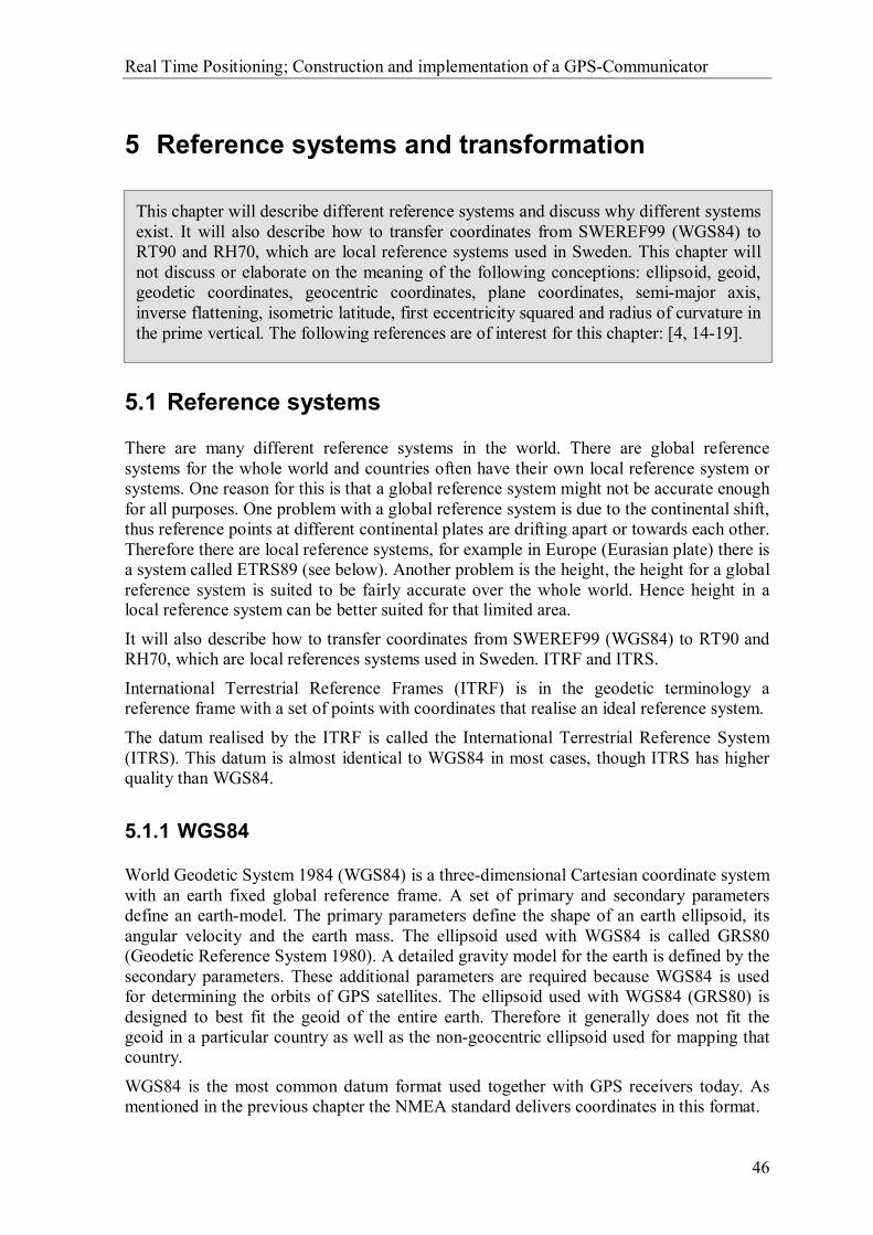
Real Time Positioning; Construction and implementation of a GPS-Communicator
46
5 Reference systems and transformation
5.1 Reference systems
There are many different reference systems in the world. There are global reference systems for the whole world and countries often have their own local reference system or systems. One reason for this is that a global reference system might not be accurate enough for all purposes. One problem with a global reference system is due to the continental shift, thus reference points at different continental plates are drifting apart or towards each other. Therefore there are local reference systems, for example in Europe (Eurasian plate) there is a system called ETRS89 (see below). Another problem is the height, the height for a global reference system is suited to be fairly accurate over the whole world. Hence height in a local reference system can be better suited for that limited area.
It will also describe how to transfer coordinates from SWEREF99 (WGS84) to RT90 and RH70, which are local references systems used in Sweden. ITRF and ITRS.
International Terrestrial Reference Frames (ITRF) is in the geodetic terminology a reference frame with a set of points with coordinates that realise an ideal reference system.
The datum realised by the ITRF is called the International Terrestrial Reference System (ITRS). This datum is almost identical to WGS84 in most cases, though ITRS has higher quality than WGS84.
5.1.1 WGS84
World Geodetic System 1984 (WGS84) is a three-dimensional Cartesian coordinate system with an earth fixed global reference frame. A set of primary and secondary parameters define an earth-model. The primary parameters define the shape of an earth ellipsoid, its angular velocity and the earth mass. The ellipsoid used with WGS84 is called GRS80 (Geodetic Reference System 1980). A detailed gravity model for the earth is defined by the secondary parameters. These additional parameters are required because WGS84 is used for determining the orbits of GPS satellites. The ellipsoid used with WGS84 (GRS80) is designed to best fit the geoid of the entire earth. Therefore it generally does not fit the geoid in a particular country as well as the non-geocentric ellipsoid used for mapping that country.
WGS84 is the most common datum format used together with GPS receivers today. As mentioned in the previous chapter the NMEA standard delivers coordinates in this format.
This chapter will describe different reference systems and discuss why different systemsexist. It will also describe how to transfer coordinates from SWEREF99 (WGS84) to RT90 and RH70, which are local reference systems used in Sweden. This chapter willnot discuss or elaborate on the meaning of the following conceptions: ellipsoid, geoid,geodetic coordinates, geocentric coordinates, plane coordinates, semi-major axis, inverse flattening, isometric latitude, first eccentricity squared and radius of curvature inthe prime vertical. The following references are of interest for this chapter: [4, 14-19].

Real Time Positioning; Construction and implementation of a GPS-Communicator
47
5.1.2 ETRS89
European Terrestrial Reference System 89 (ETRS89) is the European datum format, introduced to unify national reference systems in Europe. The system is used for monitoring tectonic and geodynamic motions in Europe and it also integrates vertical datum in Europe.
ETRS89 is a geocentric reference system that is fixed to the stable part of the Eurasian plate. With geographical coordinates based on the GRS80 ellipsoid the system is identical to ITRS89 at the epoch 1989.0. The system is defined to one centimetre accuracy and is consistent with the global ITRS. Therefore coordinates and velocities given in any ETRS89 year can be transformed into ITRS and vice versa.
5.1.3 SWEREF 99
SWEREF 99 is a Swedish realisation of ETRS 89 that is based on ITRF 97 epoch 1999. It coincides with WGS 84 within some decimetres, thus for most cases in Sweden WGS84 and SWEREF 99 can be seen as the same thing. The ellipsoid used with SWEREF 99 is the same as for WGS84 (GRS 80).
5.1.4 RT90
RT 90 (Rikets koordinatsystem 1990) is a local geodetic datum for Sweden. The national maps in Sweden are based on a Transverse Mercator grid of this datum, denoted: RT 90 2.5 gon V 0:-15. In RT90 the ellipsoid used is Bessel 1841.
5.1.5 RH70
RH 70 (Rikets höjdsystem 1970) is a local height system for Sweden.

Real Time Positioning; Construction and implementation of a GPS-Communicator
48
5.2 Transformation
Transformation is used to transform coordinates given in a specific reference system to another reference system’s coordinates. How this is done depends on which reference systems one is dealing with and even in what way one would like to transform the coordinates matters.
5.2.1 Horizontal
Coordinates measured by GPS in SWEREF 99 or WGS 84 can be transformed to the Swedish coordinate datum RT 90 using a 7-parameter transformation (estimated accuracy 7 centimetres, 1 sigma, 2D). SWEREF 99 latitude, longitude and height over the ellipsoid is transformed into plane coordinates in RT90 using the following transformation chain:
( ) ( ) ( ) ( ) 90909079999 ,),(,,,,,, RTprojectionRTRTPARSWEREFSWEREF yxZYXZYXh ⇒⇒⇒⇒ − λφλφ
First one needs to convert the SWEREF 99 (WGS84) geodetic coordinates ( )h,,λφ to decimal degrees, hence NMEA delivers the coordinates in degrees and decimal minutes. The following formula does this:
60MinutesDecimal
DegreesDegreesDecimal
βαα +=
Then the decimal degrees are converted to radians:
180πα
α∗
= DegreesDecimalRadians
As mentioned before the ellipsoid used with SWEREF 99 is GRS 80, and it has the following parameters: semi-major axis a = 6378137 metres (equatorial radius) and inverse flattening 1/f = 298.257222101. These parameters are used to calculate e2 (first eccentricity squared) and N’ (radius of curvature in the prime vertical) which is done by using these formulas:
ϕ22
2
sin1'
)2(
e
aN
ffe
−=
−=
It is now possible to transform the SWEREF 99 geodetic coordinates ( )h,,λφ to SWEREF 99 geocentric coordinates ( )ZYX ,, . The relationship between these two is:
( ) ( ) ( )( ) ( ) ( )
( )( ) ( )ϕλϕλϕ
sin1sincoscoscos
2 heNZhNYhNX
+−′=+′=+′=
The next step is to perform the transformation from SWEREF 99 geocentric coordinates ( ) 99,, SWEREFZYX to RT 90 geocentric coordinates ( ) 90,, RTZYX . This formula is used to perform the transformation:

Real Time Positioning; Construction and implementation of a GPS-Communicator
49
( )9990
1
SWEREFRTZYX
ZYX
ZYX
++
∆∆∆
=
Rδ
Where ZYX ∆∆∆ ,, are the translations between the systems, δ is the scale correction and R is the rotation matrix. R can be written as the product of the rotation matrices RX, RY and RZ (see below), which in proper order perform the rotations ZYX ωωω ,, around the x-, y- and z-axis.
( ) ( )( ) ( )
( ) ( )
( ) ( )( ) ( )( ) ( )
−
−
−==
XX
XX
YY
YY
ZZ
ZZ
XYZ
ωωωω
ωω
ωωωωωω
cossin0sincos0
001
cos0sin010
sin0cos
1000cossin0sincos
RRRR
The transformation parameters are:
mm/km 000.00000000seconds arc 516-7.0227209seconds arc 852.14134651seconds arc 314-0.8550434
metres 77516-603.06271metres 9658-41.338148
metres 67149-414.09785
==
+===∆=∆=∆
δωωω
Z
Y
X
ZYX
The arc seconds need to be converted into radians, this is done using following formula:
3600180
∗∗
=πωω ArcSeconds
Radians
It is possible to obtain the geodetic coordinates in RT 90 when one has the geocentric coordinates in RT 90. To do this one needs to use the Bessel 1841 ellipsoid with the following parameters: semi-major axis a =6377397.155 metres (equatorial radius) and inverse flattening 1/f = 299.1528128. One uses the formulas above to calculate e2 and N’ for the RT 90 system. Then it is possible to calculate the geodetic coordinates:
( )
( )
( )
−
−+
=
′−=
=
θ
θϕ
ϕ
λ
32
3
2
2
90
90
90
90
9090
cos
sin1arctan
cos
arctan
aepe
aeZ
Nph
XY
RT
RT
RT
RT
RTRT
Real Time Positioning; Construction and implementation of a GPS-Communicator
50
Where
−=
+=
2
90
902
902
1arctan
ep
Z
YXp
RT
RTRT
θ
The plane coordinate system RT 90 2.5 gon V 0:-15 used in Sweden is obtained by a Transverse Mercator (Gauss-Krüger) projection of the RT 90 latitudes and longitudes (geodetic coordinates):
( ) ( ) ( ) ( ) ( ) ( ) ( ) ( )( )( ) ( ) ( ) ( ) ( ) ( ) ( ) ( )( )ηξβηξβηξβηξβη
ηξβηξβηξβηξβξ′′+′′+′′+′′+′=′′+′′+′′+′′+′=
8sinh8cos6sinh6cos4sinh4cos2sinh2cosˆ8cosh8sin6cosh6sin4cosh4sin2cosh2sinˆ
43210
43210
akyakx
10 =k (enlargement factor)
( )
++
+=
−=
42
641
411
1ˆ
2
nnn
aa
ffn
( )( )( ) ( )( )δλϕη
δλϕξ
sincostanh
costanarctan
1 ∗−
∗
=′
=′
44
433
4322
4321
16128049561
140103
24061
1440557
53
4813
18041
165
32
21
n
nn
nnn
nnnn
=
−=
+−=
++−=
β
β
β
β
( ) ( ) ( ) ( ) ( )( )
∗=−=
+++−=∗
radians
DCBA
RT
RTRTRTRTRTRT
180777777815.8082777
sinsinsincossin
0090
906
904
902
909090
πλλλδλ
ϕϕϕϕϕϕϕ
∗ϕ is the isometric latitude and 0λ is the longitude central meridian for RT 90 2.5 gon V 0:-15 relative Greenwich (Easting).

Real Time Positioning; Construction and implementation of a GPS-Communicator
51
5.2.2 Vertical
The height ( 90RTh ) in the 7-parameter transformation described above is not accurate and should therefore not be used. To obtain an accurate height one needs to do a transformation from the height in SWEREF 99 to height in RH 70. Using a height correction model called SWEN01L does this. The height in SWEREF 99 refers to the height over the ellipsoid (h) and the height in RH 70 refers to the height over sea level (H). To obtain the height over sea level one needs to know the geoid height (N).
To obtain the accurate height in RH 70 from SWEREF 99 one uses the latitude and longitude coordinates from SWEREF 99 (decimal degrees) to interpolate a geoid height in SWEN01L. Then by using following formula one gets the height in RH 70:
LSWENSWEREFRT NhH 019970 −=

Real Time Positioning; Construction and implementation of a GPS-Communicator
52
6 Possible applications
First of all we would like to divide the applications into two separated areas. The reason is that the users in the two different groups most likely will have different needs.
Restricted users: Applications for a restricted user group such as municipal workers etc.
Public users: Applications of interests to the public.
6.1 Restricted users
The suggestions of applications given here are probably only of interest for a restricted group of users. The reasons as to why one might want to limit the number of users can be of different kind. It can for example be a question of information secrecy. It can also be such a simple reason as the application giving no value to other users than a smaller selection.
Manage and control a fleet of workers: The ability to follow all workers’ position gives a great overview and enables the possibility to direct the closest worker to the scene of action. Advisable position methods: GPS GPS does, in most cases, give sufficient accuracy on street level in cities. Though multipath and poor reception of satellite signals can interfere and give poor accuracy due to high buildings and other blocking objects. DGPS The accuracy is enough to navigate at street level inside cities without any trouble. GSM The accuracy with GSM might be enough in those situations where the workers are widely spread. The accuracy is approximately 150 metres in cities and 1.5 kilometres on the countryside.
Logging locations: It can be of interest to know where you have been. Take business travellers for example, they can easily get the “exact” route of their business trip and a calculated cost. Another interesting idea of an application could be to log workers over a longer period and determine if there are any unnecessary routines that can be eliminated or have “proof” of presence at a location at a certain time. Take
The ability to get a position in real time gives many opportunities for applications. Wewill here point out some examples to show the enormous potential this could add toGEOSECMA. The following references are of interest for this chapter: [11, 12, 49].

Real Time Positioning; Construction and implementation of a GPS-Communicator
53
sandtrucks as an example. If someone calls the highway department complaining about the lack of gritting on a particular street, then it is easy to check if or when the sandtruck was gritting the street. Advisable position methods: GPS The accuracy of GPS is sufficient because of the longer period of measurements. DGPS Gives better accuracy and is therefore also usable. The question is if the extra cost pays off.
Find the right position: In some cases it is necessary to find a location were no physical landmarks could help you. An example of this is when lime washing lakes. It is quite easy to mark the finished areas and to find those locations not yet lime washed. Advisable position methods: GPS Depends on the situation. If the accuracy is of no greater importance (lees than ten metres) GPS is advisable. DGPS In those situations when high precision is required DGPS is more advisable.
Zoom, Auto highlighting This application intends to help the user by zooming the map and highlighting the nearest object/objects. It makes it easier to find the right object on the map. Advisable position methods: GPS Depends on the situation. If the accuracy is of no greater importance GPS is advisable. For example, street corners might not require a better precision than ten metres hence the distance to the next corner is probably longer. DGPS In those situations when high precision is required DGPS is more advisable.
Alarm In those situations when a worker is alone and out of range from a nearby helping hand, an alarm feature is valuable. It can for example, be of use for forestry workers and other workgroups with isolated and lonely workplaces. Their only hope of rescue in case of an accident can be the alarm feature. One can only imagine how long it would take for someone to find them otherwise. Other thinkable minor alarm features can also be of interest. For instance the ability to report the location where you left a broken-down car will decrease the time for help to arrive.

Real Time Positioning; Construction and implementation of a GPS-Communicator
54
Advisable position methods: GPS The GPS is sufficient to give a position accurate enough to find the person in need. DGPS Gives better accuracy than GPS and is therefore also usable. GSM Can give an estimated position and can at least give a hint of the exact location.
6.2 Public users
The suggestions of public applications given here are just a selection of possible applications that we came up with during the project. They are probably of interest for a larger group of users.
I am here, what is around me? It can be quite handy to have information about the surroundings when one is at a place never visited before. Perhaps one might want to find all the restaurants in the neighbourhood. A GPS or some other positioning unit can quite simply locate your position and information on the surroundings can easily be collected from a database when the location is known. Advisable position methods: GPS The GPS is sufficient for this kind of application, hence the area of interest is the surroundings and not the exact position. DGPS Gives better accuracy than GPS and is therefore also usable. The question is if the extra cost is worth its price. GSM Can give an estimated position and perhaps give information of objects in a wider area.
Show me the best way to a chosen point if I am standing here. This application would be a great help for people who are not sure about the way. It can also be used to find the best way if there are optional ways. This requires on the other hand optimisation algorithms that can be quite resource demanding. An example of an algorithm that solves this problem is Bellman-Ford [11]. Advisable position methods: GPS In most cases gives GPS sufficient accuracy on street level in cities. Multipath and poor reception of satellite signals can however interfere and give poor accuracy due to high buildings and other blocking objects. DGPS Gives better accuracy than GPS and is therefore also usable. The question is if the extra cost is worth its price.
Real Time Positioning; Construction and implementation of a GPS-Communicator
55
GSM Can give an estimated position and perhaps give information of objects in a wider area.
Give me the best route if I want to visit a number of different locations. It is sometimes important to optimise a route. The reason can for instance be the need of decreased travel time and/or cost, which often is linked to the travel distance. The problem of optimising the distance in a route is often known as the travelling salesman problem (TSP). The problem can be quite tricky to solve if the number of locations to visit is large. Hence the number of possible routes increases dramatically for every extra location to visit and the solving time thereby also increases. There exist heuristic methods that decrease the solve time at the cost of the solution. This means that the solution might not be the best possible solution, but the solution will be good enough with respect to the solve time. Two examples of heuristic methods are “Neighbourhood search” [49] and “Simulated Annealing” [12]. A GPS or some other positioning unit can then be used to find the first/nearest location where the route will start. Advisable position methods: GPS In most cases gives GPS sufficient accuracy on street level in cities. Multipath and poor reception of satellite signals can however interfere and give poor accuracy due to high buildings and other blocking objects. The required accuracy is of course dependent on the distances between the locations to visit. DGPS Gives better accuracy than GPS and is therefore also usable. The question is if the extra cost is worth its price. GSM Can give an estimated position and might be used when the locations to visit are cities or some other destinations with large distances between them.

Real Time Positioning; Construction and implementation of a GPS-Communicator
56
7 Recommendations
7.1 Positioning methods to use
We can only recommend KORDAB to use GPS- and DGPS-receivers as positioning units. GPS has a standardised protocol NMEA 0183, see Chapter 4, that sets the norm for how position data are delivered. DGPS is only an additional complement to an ordinary GPS so the same protocol is therefore used for the final output within a DGPS-system.
All other methods mentioned in Chapter 2 have no corresponding standardisation for the delivered position data. It would not be a good idea to invest both time and money in a project that might have new conditions tomorrow. It is better to wait and see what will happen in the future and then enlarge the interface when a standardisation is set for those methods.
7.2 Communication link to use
We think that an Internet connection through an existing ISP with a GSM modem or some other mobile data telecommunication system like GPRS as carrier would be the best solution as communication link. There already is an existing web layer in GEOSECMA that uses an ordinary Internet connection for communication between the local server and the field computer. This solution will not require too much work to implement and has the advantage of none dependency on suppliers. Any provider that can offer an Internet connection will do. Another big advantage is the possibility to use new and faster carriers when they become available in the future. This would not require any changes in the software, as it is only the carrier that has changed and not the method of communicating.
If on the other hand the connection was established with a Mobitex solution there would be only a few suppliers to choose from. Only Telia and MOWIC can provide Mobitex services in Sweden at the present. They cannot offer any connection to the Internet today, so rules for the communication must be specified for this to work.
An internal radio modem network requires major construction investments and will also require maintenance during the usage. This will be very costly and is nothing we can recommend as a standard solution. We mentioned this alternative just to show that more than one alternative already exists. This could though be a good solution if the users already have a fully working radio modem network. The traffic costs will then only be dependent on the operational cost and will not be dependent on the quantity of traffic.
This chapter includes our recommendations to KORDAB based on the results obtained during the preliminary study on existing positioning units, communication alternatives and usable applications.
Real Time Positioning; Construction and implementation of a GPS-Communicator
57
7.3 Interface
The recommendation for the interface can only go in one direction. Hence we recommend KORDAB to use only GPS- and DGPS-receivers as positioning units. Our recommendation is therefore to implement NMEA 0183 capabilities into the interface that is supposed to communicate with the position unit.
We also recommend using the GGA sentence in NMEA as information source, since the current position is the only desired data from the positioning unit. GGA provides all desired data and is guaranteed as output by all GPS-receivers on the market, see Chapter 4 NMEA 0183 for more information. The interface can then be enlarged with the GSV message to increase the information given to the user.
7.4 Application
We think that KORDAB should make one or two small and simple applications that use real time positioning to begin with. They can in this way test the market and get a response and sense of what the market wants before larger efforts are made. A smaller application is most likely simpler and not too expensive to implement. Low costs give cheaper products and cheaper products are probably more easily accepted on the market. Once the users have accepted and learned to use the product, they will also hopefully realise that it is a product that they need.
A bigger and more advanced application might be more suitable later on, when the market has accepted the first implementations. The chance is also quite large that a user will come up with an own idea and new suggestions of suitable applications never thought of before, when testing the first application.
The chance of a total failure of the project can be the result if KORDAB starts with a bigger and more advanced application to begin with. A first and more advanced application can be too hard to sell in the market and the opportunity might slip through their fingers.
Our recommendations for applications are:
A zoom function to the current location in the map where you are standing. A print function that prints a map-object on the current location in the map where
you are standing.
These applications are quite simple to implement and will not scare away potential users on the market. The functionality is easy to understand and we think that they are good candidates for applications that can encourage new ideas.

Real Time Positioning; Construction and implementation of a GPS-Communicator
58
8 Prototype
To be able to connect a GPS receiver to GEOSECMA or to a webapplication, or any other software program, some extra program packages must be developed. As mentioned earlier, the GPS receiver uses a serial interface to communicate with external devices. NMEA sentences are sent through this link containing the desired position information. This chapter will describe the program package developed to communicate with the GPS. The components and functions used in the program package to handle the communication and to analyse the NMEA sentences will be described one by one in Chapter 12.2 Classes specific to the prototype package.
The package is made as an MFC7 extension DLL8 “GPS.dll”. The main source code is taken from the test program that we have developed earlier. The test program is a standalone MFC program and was made as a first step in the process to approach the program package. The reason as to why we made a standalone program to begin with is that we wanted to make sure that the needed components worked before testing them in another program like GEOSECMA. Another reason is that we did not have enough knowledge about the structure in GEOSECMA to start making changes in it.
A big disadvantage with an MFC extension DLL is that it is quite large. With large we mean that it requires four other packages to work. The four packages are:
MFC42.DLL
MSVCRT.DLL KERNEL32.DLL
USER32.DLL The MFC extension gives more features than are really needed for this GPS communication interface, such as user interface functionality and interaction etc. The package can be rebuilt however so that it does not need all of these extra packages and in that way also decrease the “size”. We decided to go through with the MFC extension even though there was a the big disadvantage. In this why we could reuse the old code from the test program without too many changes. The time factor was a big motive for this decision. It would have taken more work and time than it would have given profit to rewrite the code. The prototype is only developed to show that it is possible to collect position data into GEOSECMA.
7 MFC – Microsoft Foundation Classes
8 DLL – Dynamic Link Library
This chapter will describe our prototype interface for GPS- and DGPS-receivers. The prototype was made as an example to show how an interface might be constructed. The prototype is, at the moment, only working on computers with Windows 9x- and NT-based operating systems. Implementation for Windows CE is not yet implemented. Thefollowing references are of interest for this chapter: [37]
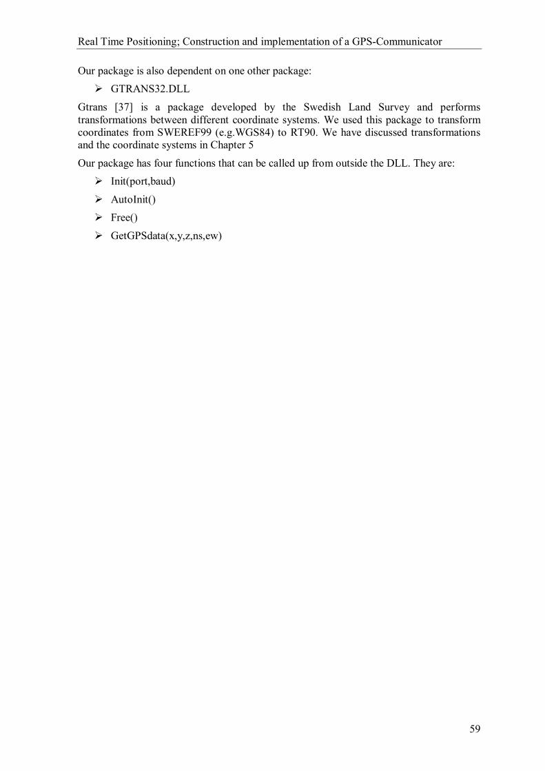
Real Time Positioning; Construction and implementation of a GPS-Communicator
59
Our package is also dependent on one other package: GTRANS32.DLL
Gtrans [37] is a package developed by the Swedish Land Survey and performs transformations between different coordinate systems. We used this package to transform coordinates from SWEREF99 (e.g.WGS84) to RT90. We have discussed transformations and the coordinate systems in Chapter 5
Our package has four functions that can be called up from outside the DLL. They are: Init(port,baud)
AutoInit() Free()
GetGPSdata(x,y,z,ns,ew)
Real Time Positioning; Construction and implementation of a GPS-Communicator
60
8.1 Init(port,baud)
The function Init initialises a serial communication port with the given input parameters port and baud, it then scans it for a GPS receiver. A worker thread starts reading GGA9 messages from the port if a GPS is actually found. It is then possible to use GetGPSdata(x,y,z,ns,ew) to collect position data from the GPS from outside the DLL.
Is GPS connected? Star thread
ReturnThread
already running
ReturnPort occupied
Threadinactive?
ReturnGPS not connected
Returnok
Flag threadactive
Is port available?
Setup Port
No
Yes Yes
No No
Yes
Init
Figure 8.1 - Flow diagram for Init (Port,Baud).
The function returns a status value to indicate the result of the call. There are four status values that can be returned:
0 – Everything OK. A GPS receiver was found at the requested port and reading from the GPS has started. GetGPSdata can now deliver data from the GPS
1 – The requested port was occupied. GetGPSdata cannot be used. 2 – No GPS was connected at the requested port. GetGPSdata cannot be used.
3 – A worker thread reading from the communication port is already running. No new thread can therefore be started. GetGPSdata can probably be used but there are no guaranties for the delivered data if any are given at all.
9 GGA – NMEA sentence with Time, Position and Fix related data for a GPS receiver.

Real Time Positioning; Construction and implementation of a GPS-Communicator
61
8.2 AutoInit()
The AutoInit function does the same thing as Init(port,baud), with the difference that it scans every available serial communication port for a GPS receiver. A worker thread starts reading GGA messages if a GPS actually is found on one of the ports. It is then possible to use GetGPSdata(x,y,z,ns,ew) to collect position data from the GPS from outside the DLL.
AutoInit
PortIndex = 0
BaudIndex = 0
BaudIndex<
Max
Init(PortIndex,BaudIndex)
OK?
ReturnOK
BaudIndex++
PortIndex++
PortIndex<
Max
ReturnFAIL
Yes
Yes
YesNo
No
No
Figure 8.2 - Flow diagram for AutoInit().
The function returns a status value to indicate the result of the call. There are two status values that can be returned:
0 – Everything OK. A GPS receiver was found at one of the ports and reading from the GPS has started. GetGPSdata can now deliver data from the GPS.
1 – No GPS was found.
Real Time Positioning; Construction and implementation of a GPS-Communicator
62
8.3 GetGPSdata(x,y,z,ns,ew)
The GetGPSdata function collects, transforms and returns position data if there are any new valid data available. The in-parameters are references to the memory bank so the returned data will be located inside those parameters inserted in the call of the function. The parameters ns and ew are no longer asserted. They are a remainder from the test program when we did not transform the coordinates. So the contents of them can be rejected after the function call.
The position coordinates are transformed from SWEREF99 (e.g. WGS84) to RT90 2.5 gon V 0:-15 using the program package Gtrans32 from the Swedish Land Survey. Gtrans can be used as a component in an application, and such applications may be developed freely, although the end user must obtain a license to use Gtrans. In other words, Gtrans may not be freely distributed along with the application. The license costs 1000 SEK.
We use Gtrans for the transformation from SWEREF99 to RT90. The position given in the NMEA sentence GGA is in the WGS84 datum given as degrees and minutes. SWEREF99 and WGS84 are almost identical. So the difference between them is minor and will not affect transformations of position given with accuracy no better than a metre. The accuracy of the position measured by the GPS is not better than a metre so we can therefore use the transformation from SWEREF99 instead of WGS84. Gtrans requires SWEREF99 however to be in the format decimal degrees to be able to execute the transformation. So a simple transformation from degrees and minutes to decimal degrees must first be done. Every degree is 60 minutes so the transformation from degrees and minutes to decimal degrees is quite simple. See Chapter 5 for more information about transformation and reference systems.
The idea is to move this transformation outside the package later on. The reason to why it is placed inside the package at this time is the lack of corresponding functionality in GEOSECMA today. Appendix 12.3 shows an example of how this transformation could be done without Gtrans. The code in the appendix is written for MATLAB but it would not be too hard to convert it into C++ code. One can either convert it by hand or use the “mcc” command in MATLAB. Mcc is a command that automatically converts MATLAB-code into “C”- or “C++”-code.

Real Time Positioning; Construction and implementation of a GPS-Communicator
63
GetGPSdata
New dataavailable? &
GPS fix?
GetGPSData()
Transform WGS84 to RT90
ReturnNo valid fix
ReturnNo new data
ReturnOK
Set postiondata
Yes
No fixNo new data
Figure 8.3 - Flow diagram for GetGPSdata.
The function returns a status value to indicate the result of the call. There are three status values that can be returned:
0 – Everything OK. New valid data from the GPS are available in the parameters x ,y, z
1 – New data where available but it had no valid fix.
2 – No new data are available.
Real Time Positioning; Construction and implementation of a GPS-Communicator
64
8.4 Free
The Free function ends the thread that reads the data from the GPS and closes the serial communication port. GetGPSdata(x,y,z,ns,ew) can no longer be used to get position data. A flow diagram is not necessary to explain this function. It would only consist of one block showing the variable that tells that the thread should end.

Real Time Positioning; Construction and implementation of a GPS-Communicator
65
8.5 Typical uses of the interface
We will here show some typical uses of the package. The examples are partly written in pseudocode and all function calls to the packages are written in real C++ code. Contents inside [] are pseudocode and text written in bold is real C++ code.
[Import the package and associate the functions in the package. Check if the package got imported ok.] . . Insert own code for graphical interface and interaction with the user. .
******Create the following action event handlers****** if ([button connect2GPS clicked]) { if(AutoInit() = = 0) { [GPS is connected, Set GetGPSdata available.] } else { [No GPS is connected, Set GetGPSdata not available. Try to connect again or make user aware of the situation.] } } if ([getPosition button clicked and GetGPSdata is available]) { if(GetGPSdata(x,y,z,ns,ew) = = 0) { [Present the given position data in x , y, z to the user.] } else { [Inform the user that no new valid position was retrieved.] } } If ([disconnect from GPS button clicked]) { Free(); [Set GetGPSdata not available.] } ******END action event handlers******

Real Time Positioning; Construction and implementation of a GPS-Communicator
66
9 Conclusions
The recommendations given in chapter 7 are based on the survey in chapter 2 and 3 and on our own opinions of their out-coming, future and reliability. The GPS-system has been in function for a long time and the future of the system seems secure and reliable. Furthermore, the development of the European project Galileo strengthens the use of a satellite-based positioning system. Other positioning systems like GSM-positioning are still in the developmental stage and at this moment there is no worldwide-standardization available. Several different methods exist for how the position data are delivered to the end user. We can therefore not see how this system can be secure and reliable in the future. A worldwide-standard would on the other hand put this system in a stronger position. Mobile phones are common in today’s society and would be a good complement to the GPS-system that has no coverage indoors.
Mobile Internet connections are very secure and reliable with respect to future existence. We believe that several different kinds of mobile Internet connections will exist in the future to choose from. If provided through a cellular phone company or some other type of provider does not matter; it is just the connection to the Internet that is important and not the carrier.
The prototype is made to exemplify that real time positioning in GEOSECMA is possible. We have not tried to make the prototype as optimised as possible. The main target was to prove that real time positioning is possible. Therefore we have only made sure that the necessary functions worked in a satisfactory way. The functionality of the prototype has shown good results and is working fully. The first implemented application in GEOSECMA was a “print a map-object at current position” feature. Tests with this application have shown that the map-objects are placed in the map within acceptable radii from the true position.
We hope and feel that our work has answered KORDAB’s questions in a satisfying way. The result will hopefully lead to the implantation of a real time positioning feature in GEOSECMA in the future, which will be available for KORDAB’s customers.
This chapter includes our conclusions based on our survey and work. It is basically asummery of chapter 7 and 8.

Real Time Positioning; Construction and implementation of a GPS-Communicator
67
10 Tips
10.1 Simulate a GPS
During the development stage we realised that we needed to simulate a GPS. The GPS cannot be used indoors without an external antenna outside, because of the need of a free line of sight to the satellites. One problem with an external antenna hanging out from a window is that it still can be difficult to get signals from a sufficient number of satellites.
Instead of using a real GPS receiver as source for the GPS data, we used an ordinary terminal program. The terminal program is fully capable of emulating a GPS receiver. The only thing needed is a text file with the same information that a GPS outputs. Logging the outgoing data from a GPS connected to a terminal program easily makes this file. This requires, on the other hand, that one has access to a portable computer to take outside, where the GPS can receive signals from at least 3 satellites and get a fix. The file can also be made by hand but this would take much longer time and is not something we recommend unless the content is repeated. The lines can then easily be copied.
For more information on how to establish a serial communication and how to send or log files with a terminal program, see chapter 12.1 Simulate a GPS with a terminal program.
You can also find a number of different programs that simulate a GPS receiver on the Internet. Although we did not find any that were much better than an ordinary terminal program and all of those that we found were so called shareware10. Here is one example of those GPS simulation programs we tested.
RecSim III [7]
10 Shareware is software that is distributed free on a trial basis
This chapter will give a few tips that can be useful for those who are new to GPS-receivers. The following references are of interest for this chapter: [7-9, 13]

Real Time Positioning; Construction and implementation of a GPS-Communicator
68
10.2 GPS utilities
There are several useful GPS utility software programs that can be good to know about. We find them useful in those situations when the GPS cannot get a fixed position. The programs often give information on which satellites the GPS can see and which of them is being used for measurement. From this information you can often from this information diagnose why GPS cannot get a fixed position. The following software programs are a selection of many existing utilities:
GPSClient: This is our own test program developed during the project.
GPSDiag [9]: This is a very useful program that shows all available information on each satellite in view. You can also log the NMEA output from the GPS into files.
Visual GPS [8]: Possibility to see a graphic representation of current satellites in view.
10.3 GPS satellite prediction
It can be useful to know in advance how the conditions will be at a certain point while measuring the position with a GPS receiver. The Swedish Land survey runs a service on their website [13] that can predict the satellite constellation at a specific time seen from a predestinated location. The table below shows the number of expected satellites which will have an elevation angle greater than ten degrees between one and two o'clock on May 28 2002 at the coordinates 56°10' N latitude and Lon=15°36' E longitude. The figure below the table shows the satellites’ constellation. With the help of this service one can determine the best time for measurement and avoid the risk of ending up in a situation when very few satellites will be available for measurement.
Time Number of satellites
13:00 6
13:10 6
13:20 6
13:30 5
13:40 6
13:50 6
14:00 6
Real Time Positioning; Construction and implementation of a GPS-Communicator
69
Figure 10.1 – Shows the predicted GPS Satellite constellation.

Real Time Positioning; Construction and implementation of a GPS-Communicator
70
11 References [1] Guide to GPS positioning Davids Wells Canadian GPS association, 1987 ISBN 0-920-114-73-3
[2] Fundamentals of global positioning system receivers: a software approach Tsui, James Bao-yen New York, Wiley, cop. 2000 ISBN 0471381543
[3] RTCM paper 194-93/SC104-STD, Version 2.1 RTCM Special Committee NO. 104 Radio Technical Commission For Marine Services, January 3, 1994
[4] Handbok Geodesi, GPS Lantmäteriverket, Gävle, 1993, 1996 ISBN 91-7774-061-0
[5] The NMEA 0183 Protocol Klaus Betke, May 2000, Revised August 2001 http://longwave.bei.t-online.de/0183.pdf 2002-05-09
[6] Tera Term, a terminal program. http://hp.vector.co.jp/authors/VA002416/teraterm.html 2002-05-27
[7] RecSim, a NMEA simulation program. http://www.effective-solutions.co.uk/recsim.html 2002-05-27
[8] VisualGPS, a GPS utility. http://www.apollocom.com/VisualGPS/default.htm 2002-05-27
[9] GPSDiag, a GPS utility. http://asia.cnet.com/downloads/pc/swinfo/0,39000587,20048924s,00.htm 2002-05-27
[10] Geolocation and Assisted GPS Goran M. Djuknic and Robert E. Richton Bell Laboratories, Lucent Technologies http://www.cs.huji.ac.il/~postPC/Geolocation_assistedGPS.pdf 2002-05-04
[11] Shortest path algorithm, Bellman-Ford http://www.ece.nwu.edu/~guanghui/Transportation/spt/spt.html 2002-05-27
[12] Travelling salesman problem algorithm, Simulated Annealing http://serendipity.magnet.ch/hermetic/misc/ts3/ts3demo.htm 2002-05-27

Real Time Positioning; Construction and implementation of a GPS-Communicator
71
[13] GPS satellite prediction http://swepos.lmv.lm.se/pre/in.asp 2002-05-27
[14] New Approach on The Improvement of DGPS Positioning Accuracy Using the RLSLFs and a Kalman Filter http://www.icspat.com/papers/94mfi.pdf 2002-04-26
[14] Coordinate transformations http://www.lm.se/geodesi/refsys/transform/transform.htm 2002-05-23
[15] Transformation SWEREF 99 to RT 90 http://www.lm.se/geodesi/refsys/sweref-rt/sweref99-rt90.htm 2002-05-23
[16] LMV-rapport 2001:07 Transformationssamband mellan SWEREF 99 och RT 90/RH 70. Jivall L, Lidberg M, Lilje M, Reit B-G 2002-05-24
[17] Geodetic reference systems http://www.lm.se/geodesi/refsys/geod_refsyst.htm 2002-05-22
[18] World geodetic system 1984 http://www.wgs84.com/wgs84/wgs84.htm 2002-05-22
[19] European Terrestrial Reference System 89 http://www.euref-iag.org/ 2002-05-21
[20] UMTS Overview http://www.umtsworld.com/technology/overview.htm 2002-05-17
[21] UMTS http://www.nt.tuwien.ac.at/mobile/projects/UMTS/en/ 2002-05-17
[22] Nokia GPRS http://www.nokia.com/gprs/qa_starting.html 2002-05-15
[23] GPRS presentations in HUT http://www.cs.hut.fi/~hhk/GPRS/lect/telecomforum/ppframe.htm 2002-05-15
[24] Ericsson GC75 technical specification http://www.communica.se/ericsson/sonyericsson_gc75.pdf 2002-05-12
[25] Conventional GSM data service (how GSM data works) http://www.cs.hut.fi/~hhk/GPRS/lect/gsmdata/ppframe.htm 2002-05-13

Real Time Positioning; Construction and implementation of a GPS-Communicator
72
[26] LMV-rapport 1991:4 Kort introduktion till GPS Jonsson Bo Lantmäteriverket, Gävle 1991
[27] How GPS Works http://www.mercat.com/QUEST/HowWorks.htm 2002-04-14
[28] SWEPOS Produkter http://swepos.lmv.lm.se/index_prod.htm 2002-04-27
[29] SWEPOS OmniSTAR http://swepos.lmv.lm.se/omnistar.htm 2002-05-27
[30] OmniSTAR http://www.omnistar.nl/ 2002-04-27
[31] SWEPOS Mobipos http://swepos.lmv.lm.se/generic.htm 2002-04-27
[32] What is WAAS? http://www.garmin.com/aboutGPS/waas.html 2002-04-28
[33] SWEPOS utveckling, RTK http://swepos.lmv.lm.se/utveckling.htm 2002-04-23
[34] Ericsson Mobitex http://www.ericsson.com/network_operators/mobitex/ 2002-05-09
[35] MOWIC kommunikation http://www.mowic.se/kommunikation.htm 2002-05-10
[36] Telia Mobitex http://www.mobitex.telia.com/ 2002-05-10
[37] Program Beskrivning, Exporterade subrutinanrop (exported function calls) Hans Granegård National Land Survey if Sweden 2000-02-23
[38] Föreläsning 2a, GPS-observationer och felkällor Lotti Jivall Lecture Notes Högskolan i Gävle 2001-02-08
[39] Carrier phase GPS http://www.trimble.com/gps/codevscarrier.html 2002-05-10
Real Time Positioning; Construction and implementation of a GPS-Communicator
73
[40] DGPS http://www.trimble.com/gps/dgps.html 2002-04-13
[41] GSM positioning http://location.vtt.fi/source/technologies.html 2002-04-29
[42] Localization of mobile devices of mobile devices Seminar: Mobile Computing IFW C42 Roger Zimmermann Tuesday, 29th May 2001 http://www.inf.ethz.ch/vs/edu/SS2001/MC/slides/07-location.pdf
[43] Overview of 2G LCS Technologies and Standards 3GPP TSG SA2 LCS Workshop LCS-010019 London, UK, 11 – 12 January 2001 http://www.3gpp.org/ftp/workshop/Archive/0101LCS/Docs/PDF/LCS-010019.pdf 2002-04-29
[44] Ciceron DGPS http://www.cartesia.se/produkter.asp?Namn=Ciceron 2002-04-27
[45] Epos DGPS http://www.cartesia.se/produkter.asp?Namn=Epos 2002-04-27
[46] Sjöfartsverket DGPS http://www.sjofartsverket.se/tabla-a/pdf/a175_1.pdf 2002-04-27
[47] NMEA 0183 http://www.kh-gps.de/nmea-faq.htm 2002-05-10
[48] NMEA 0183 http://www.nolandengineering.com/nmeainfo.html 2002-05-10
[49] Travelling salesman problem algorithm, Neigbourhood search http://www.ida.liu.se/~TDTS01/lectures/lec8.pdf 2002-05-10

Real Time Positioning; Construction and implementation of a GPS-Communicator
74
12 Appendix
12.1 Simulate a GPS with a terminal program
It is quite simple to simulate a GPS-receiver with the use of an ordinary terminal program. The only requirements are that the terminal program is able to send text files as ASCII11-code. You will also need a text file containing the same information as GPS-receiver outputs. The GPS-application will see no difference between a real GPS-receiver and the simulated GPS through the terminal program.
The terminal program used in this example is Tera Term, which can be freely downloaded from Tera Term’s homepage [6]. A simulation could be done with any other terminal program that can send text files as ASCII. We recommend though that you do not use Microsoft’s Hyper Terminal. We have experienced some trouble with this program. It has some tendencies to send strange characters when it does not recognise the actual character to be sent. This can lead to unwanted behaviour in the GPS application.
12.1.1 Physical Connection
There are two alternatives to achieve the physical connection. You could either run the terminal program and the GPS-application on two different computers or on the same computer. Use Alternative 1 if you run them on two different computers and Alternative 2 if you run them on the same computer, see figure below. The communication ports declared in the figure are only suggestions. You might need to change to other ports better suiting your computer’s configuration.
11 ASCII – American Standard Code for Information Interchange. ASCII code is the numerical representation of a character such as 'a' or '@' or an action of some sort

Real Time Positioning; Construction and implementation of a GPS-Communicator
75
12.1.2 Setup connection
1) Open Tera Term and select the radio button ”Serial” in the opened dialogue. Then select the port where you have connected your device.
Now click OK
2) Open the “Setup”-menu and choose “Serial port”

Real Time Positioning; Construction and implementation of a GPS-Communicator
76
3) Change the fields in the opened dialogue as has been done below. Note that the Port must be the same as you selected in step 1. You will most likely only need to change the “Baud rate”-field. If you only want to send one type of message like GGA, we recommend that you set the transmit delay parameter to 1000 mesc/line. An ordinary GPS does not send all messages at continuous flow. It actually makes small delays between each set of messages it sends. If there were many messages per set, there would be no noticeable delay. The delay will on the other hand be more obvious when only a few messages per set are sent. The terminal program can only handle delays per line so do not set this parameter if there are more than one message per set.
Now click OK.

Real Time Positioning; Construction and implementation of a GPS-Communicator
77
4) Open the “Setup”-menu and choose Terminal.
5) Change the fields in the “New-line” section as shown below.
Now click OK.
6) You have now configured the serial communication and are ready to send or log files.

Real Time Positioning; Construction and implementation of a GPS-Communicator
78
12.1.3 Send file
1) Open the “File”-menu and choose Send file.
2) Select the file that you want to send in the browser dialogue that has opened. The transfer will start as soon as you press the “Open”-button.
3) A dialogue opens when you have pressed the “Open”-button showing the transfer. You can Close or Pause the transfer by pressing the respectively button in the dialogue.

Real Time Positioning; Construction and implementation of a GPS-Communicator
79
12.1.4 Log file
1) Open the “File”-menu and choose log…
2) Select the location and filename for the log file in the browser dialogue that has opened. The logging will start as soon as you press the “Open”-button.
3) A new dialogue opens in minimized mode when the logging has started. You can Pause and Close the log by pressing the respective button in the dialogue.
Real Time Positioning; Construction and implementation of a GPS-Communicator
80
Real Time Positioning; Construction and implementation of a GPS-Communicator
81
12.2 Classes specific to the prototype package
12.2.1 Class CGPSReadData
Description: The class CGPSReadData is the thread-object that handles the reading from the GPS.
Defining h-file: CGPSReadData.hpp
Attributes: Public
CWinThread * m_thread;
A worker thread
UINT newvalue;
Flag that indicates if new GPS data has been set since last GetGPSdata call.(0 = new data has been set and 1 = no new data since last call)
Methods: Public
void Reset(void);
Resets the thread to NULL.
Returns: -
UINT GetGPSdata(GPSdata &g1);
Set g1 with new GPS data if it has been updated since last call.
Returns: 0 : if new data where available.
1 : if no new data where available.
void SetGPSdata(GPSdata g1);
Sets new GPSdata.
Returns: -

Real Time Positioning; Construction and implementation of a GPS-Communicator
82
12.2.2 Class GGA
Description: The class GGA is a data object corresponding to the GGA message in NMEA 0183.
Field Number: 11 1 2 3 4 5 6 7 8 9 10 | 12 13 14 15 | | | | | | | | | | | | | | | $--GGA,hhmmss.ss,llll.ll,a,yyyyy.yy,a,x,xx,x.x,x.x,M,x.x,M,x.x,xxxx*hh<CR><LF>
Defining h-file: GGA.hhp
Attributes: Public
CString UTCTime;
Field 1: Holds the UTCTime. Formatted as “hhmmss.ss” hours, minutes and seconds.
CString Latitude;
Field 2: Holds the Latitude. Formatted as “llll.ll” First two ll is Degrees, the following two ll is in minutes and the last two .ll is decimal minutes.
CString NS;
Field 3: Tells if the position is on the Northern or Southern hemisphere. Can be either N = North or S = South.
CString Longitude;
Field 4: Holds the Longitude. Formatted as “yyyyy.yy” First three yyy is Degrees, the following two yy is minutes and the last two .yy is decimal minutes.
CString EW;
Field 5: Tells if the position is on the Eastern or Western hemisphere. Can be either E = East or W = West.
CString GPSQuality;
Filed 6: Holds a GPS Quality Indicator. It has three different states:0 – Fix not available. 1 – GPS fix. 2 – Differential GPS fix.
CString NumberOfSatellitesInUse;
Field 7: Indicates the number of satellites being used for the measurement. Note that this is not the number of satellites in view.
CString HorizontalDilutionOfPrecision;
Field 8: Holds the horizontal dilution of precision.
CString AntennaAltitudeMetres;
Field 9: Holds the antenna altitude above/below geoid.
CString UnitsOfAntennaAltitude;

Real Time Positioning; Construction and implementation of a GPS-Communicator
83
Field 10: Indicates the unit to associate with field 9.
CString GeoidalSeparationMetres;
Field 11: Holds the Geoidal separation, the difference between the WGS-84 earth ellipsoid and geoid, "-" means mean-sea-level below ellipsoid.
CString UnitsOfGeoidalSeparationMetres;
Field 12: Holds the Units of geoidal separation, metres.
CString AgeOfDifferentialGPSDataSeconds;
Field 13: Holds the age of the differential GPS data. Is given as time in seconds since last RTCM SC104 type 1 or 9 where updated. Null field when DGPS is not used.
CString DifferentialReferenceStationID;
Field 14: Holds the differential reference station ID. [0000-1023]
CString Checksum;
Field 15: Holds the Checksum. Starts with an * followed by a hexadecimal value
Methods: Public
void Empty( void );
Sets the object as an empty object.
Returns: -
int Parse(SENTENCE&);
Parses the provided sentence and sets the GGA attributes.
Returns: 0 : if successfully parsed as a GGA message. 1 : otherwise.

Real Time Positioning; Construction and implementation of a GPS-Communicator
84
12.2.3 Class GPSdata
Description: The class GPSdata is the data object that contains the messages read from the GPS. At this time only a GGA object is inserted. The idea is to insert other attributes when or if they are needed later on.
Defining h-file: GPSdata.hpp Attributes: Public
GGA gga;
NMEA sentence with Time, Position and Fix related data for a GPS receiver
Methods: Public
void Empty( void );
Removes the contents of gga
Returns: -
void Set(GGA g1);
Sets the GGA attribute gga to the same as g1
Returns: -
12.2.4 Class RS232_COM
Description: The class RS232_COM is a component that supplies a serial communication link. The object has attributes that set the serial communication parameters. It has a number of functions to handle the communication as well. The bold attribute alternatives are set as default in the table below.
Defining h-file: RS232_COM.hhp
Attributes: Protected
LPCTSTR Port;
Holds the communication port to be used. {COM1 , COM2 , COM3 , COM4 }
DWORD BaudRate;
Holds the baud rate to be used. {110,300,600,1200,2400,4800,9600,14400,19200,38400,56000,57600,115200,128000,25600}
BYTE ByteSize;
Holds the byte size to be used.
Real Time Positioning; Construction and implementation of a GPS-Communicator
85
{7,8}
BYTE Parity;
Holds the parity to be used. { EVENPARITY , MARKPARITY , NOPARITY , ODDPARITY , SPACEPARITY }
BYTE StopBits;
Holds the number of stop bits to be used. { ONESTOPBIT , ONE5STOPBITS , TWOSTOPBITS }
BYTE isopen;
Holds information of if the connection is open or not.
{ IsOpen=0 , NotOpen=1 }
HANDLE hCom;
Holds a handle for the connection.
Methods:
DWORD RS232_open();
Opens the serial communication link with the above attributes as parameters.
Returns: 0 : if successful opened.
1 : if requested port is busy. 2 : if communication parameters can not be set.
void RS232_close();
Closes the communication link.
Returns: -
DWORD RS232_set(LPCTSTR port,DWORD baudrate, BYTE bytesize, BYTE parity, BYTE stopbits);
This function sets the serial communication parameters.
Returns: 0 : when the parameters are set.
DWORD RS232_read(unsigned char *c);
This function reads one character on the connected port.
Returns the length of the character 0 : if no character was collected. The variable c cannot be trusted.
1 : if a character was collected. The variable c contains the collected character.
Real Time Positioning; Construction and implementation of a GPS-Communicator
86
DWORD RS232_send(unsigned char c);
This function sends a character on the connected port. Returns:
0 : when the character has been sent.
DWORD RS232_isOpen();
This function checks if there is an active connection.
Returns: 0 : if there is an active connection.
1 : otherwise.
UINT IsGPSconnected(LPCTSTR &port,DWORD &baudrate);
This function checks if there is a GPS-receiver on the connected port.
Returns: 0 : if there is a GPS connected. 1 : otherwise
DWORD RS232_search(LPCTSTR &port, DWORD &baudrate);
This function scans the ports with different baud rates. Searching for a connected GPS-device.
Returns:
0 : if a GPS-device is detected. The variables port and baudrate will then contain the correct values to use to establish a connection with the device. The connection will not be remaining after detection in this function.
1 : if no communication ports were available. The variables port and baudrate are not to trust.
2 : No device were found. The variables port and baudrate are not to be trusted
12.2.5 Class SENTENCE
Description: The class SENTENCE is a general sentence object. It can contain all sentences delivered in NMEA. The object has one attribute that contains the sentence. It has a number of functions to handle and operate on the sentence as well.
Defining h-file: SENTENCE.hpp Attributes: Protected
CString Sentence;
Holds the sentence. Should start with a ‘$’-character to indicate that it is a proper sentence.

Real Time Positioning; Construction and implementation of a GPS-Communicator
87
Methods:
int ComputeChecksum( void );
This function computes the checksum of the attribute Sentence.
Returns: the computed value as an integer.
CString Field( int field_number );
This function selects the filed object corresponding to field_number in the attribute Sentence.
Returns: the selected field as a CString.
int GetNumberOfDataFields( void );
This function counts the number of fields in the attribute Sentence.
Returns: the counted number as an integer.
void Set_Sentence(CString &s1);
This function sets the attribute Sentence to s1.
Returns: -
DWORD ReadSentence(CString &messagetype,RS232_COM &com, bool multimessage);
This function reads a sentence from the connection established in com. The type of message to read is defined by messagetype and the result is set to the attribute Sentence. Some messages might need to be divided into more than one sentence. Sentences that require more than 80 characters fall under this category, hence each sentence can only contain 80 characters. The parameter multimessage indicates if the sentence can be divided into one or more sentence. The value true indicates that more than one sentence might be used if needed. Do not set this parameter to true unless the desired message type can be divided into several sentences.
Returns : 0 : if desired sentence was found. 1 : if the desired sentence was not found or no connection was established.
void SendSentence(RS232_COM &com);
This function sends the attribute Sentence on the connection established in com.
Returns : -
Real Time Positioning; Construction and implementation of a GPS-Communicator
88
12.3 Transformation: SWEREF99 to RT90 %MATLAB source code
%Transformation from SWEREF99 to RT90 gon V 0:-15
function p=sweref99_rt90(x_grad, y_grad, z)
x = x_grad*pi/180; % radians y = y_grad*pi/180; % radians
a = 6378137; % metres f = 1/298.257222101; e_2 = f*(2-f); N = a / ( sqrt( 1-e_2*sin(x)*sin(x) ) );
% Geocentric coordinates SWEREF99 X_sweref99 = ( N+z )*cos(x)*cos(y); Y_sweref99 = ( N+z )*cos(x)*sin(y); Z_sweref99 = ( N*( 1-e_2 )+z )*sin(x);
delta_X = -414.0978567149; % metres delta_Y = -41.3381489658; % metres delta_Z = -603.0627177516; % metres
w_X_tmp = -0.8550434314/3600; % degrees w_Y_tmp = 2.1413465185/3600; % degrees w_Z_tmp = -7.0227209516/3600; % degrees
w_X = w_X_tmp*pi/180; % radians w_Y = w_Y_tmp*pi/180; % radians w_Z = w_Z_tmp*pi/180; % radians
R_Z = [cos(w_Z) sin(w_Z) 0; -sin(w_Z) cos(w_Z) 0; 0 0 1]; R_Y = [cos(w_Y) 0 -sin(w_Y); 0 1 0; sin(w_Y) 0 cos(w_Y)]; R_X = [1 0 0; 0 cos(w_X) sin(w_X); 0 -sin(w_X) cos(w_X)]; R = R_Z * R_Y * R_X;
X_Y_Z_RT90 = [delta_X; delta_Y; delta_Z] + R * [X_sweref99; Y_sweref99; Z_sweref99];
% Geocentric coordinates RT90 X_RT90 = X_Y_Z_RT90(1); Y_RT90 = X_Y_Z_RT90(2); Z_RT90 = X_Y_Z_RT90(3);
a = 6377397.155; % metres f = 1/299.1528128; e_2 = f*(2-f); N = a / ( sqrt( 1-e_2*sin(x)*sin(x) ) );
y_RT90 = atan(Y_RT90/X_RT90); p = sqrt( (X_RT90^2+Y_RT90^2) ); theta = atan( Z_RT90 / ( p * sqrt( (1-e_2) ) ) );
tmp = ( Z_RT90 + ( (a*e_2)/sqrt( (1-e_2) ) )*sin(theta)*sin(theta)*sin(theta) ); tmp2 = p-a*e_2*cos(theta)*cos(theta)*cos(theta);
x_RT90 = atan( tmp/tmp2 );
% Geodetic coordinates RT90 (decimal degrees) x_RT90_grad = x_RT90*180/pi; y_RT90_grad = y_RT90*180/pi; z_RT90 = p/cos(x_RT90) – N;
A = e_2; B = (1/6) * (5*e_2^2-e_2^3);
Real Time Positioning; Construction and implementation of a GPS-Communicator
89
C = (1/120) * (104*e_2^3 - 45*e_2^4); D = (1/1260) * (1237*e_2^4);
delta_lamdba = y_RT90 - (15.80827777777778*pi/180); fi = x_RT90 - sin(x_RT90)*cos(x_RT90)*(A+B*(sin(x_RT90))^2+C*(sin(x_RT90))^4+D*(sin(x_RT90))^6); G = atan((tan(fi)/cos(delta_lamdba))); N = atanh((cos(fi)*sin(delta_lamdba)));
k=1; n = f/(2-f); a_tak = (a/(1+n)) * (1 + (1/4)*n^2 + (1/64)*n^4);
B_1 = (1/2)*n - (2/3)*n^2 + (5/16)*n^3 + (41/180)*n^4; B_2 = (13/48)*n^2 - (3/5)*n^3 + (557/1440)*n^4; B_3 = (61/240)*n^3 - (103/140)*n^4; B_4 = (49561/161280)*n^4;
x_RT90_plan=k*a_tak*(G+(B_1*sin(2*G)*cosh(2*N))+(B_2*sin(4*G)*cosh(4*N))+(B_3*sin(6*G)*cosh(6*N))+(B_4*sin(8*G)*cosh(8*N)));
y_RT90_plan=k*a_tak*(N+B_1*cos(2*G)*sinh(2*N)+B_2*cos(4*G)*sinh(4*N)+B_3*cos(6*G)*sinh(6*N) +B_4*cos(8*G)*sinh(8*N))+1500000;
% Plane Geodetic coordinates RT 90 2.5 gon V 0:-15 (x, y) p=[x_RT90_plan y_RT90_plan z_RT90];

Real Time Positioning; Construction and implementation of a GPS-Communicator
90
12.4 Test measurement
SA Watch is a software used to monitor and analyse the results from your GPS receiver when it is placed at a fixed location. You will normally get different position results form your GPS receiver even though it has not moved, one usually calls this wandering. Originally, this wandering was largely the result of SA (Selective Availability). Now when the SA signal is no longer in use one still experience a small wandering.
We have made some test measures to see how big this wandering is. The measures are made at one exact known location given by the Swedish land survey. The time period for each test measures is approximately eight minutes. The number of satellites during the tests have been four to six at each measurement.
The picture below shows the results of one of these measurements. The weighted mean value (the pink circle) of the error is placed within 1.2 metre radius from the real location. The outer circle has a diameter of 6.3 metre and shows that the error never exceeds this limit.

På svenska Detta dokument hålls tillgängligt på Internet – eller dess framtida ersättare – under en längre tid från publiceringsdatum under förutsättning att inga extra-ordinära omständigheter uppstår.
Tillgång till dokumentet innebär tillstånd för var och en att läsa, ladda ner, skriva ut enstaka kopior för enskilt bruk och att använda det oförändrat för ickekommersiell forskning och för undervisning. Överföring av upphovsrätten vid en senare tidpunkt kan inte upphäva detta tillstånd. All annan användning av dokumentet kräver upphovsmannens medgivande. För att garantera äktheten, säkerheten och tillgängligheten finns det lösningar av teknisk och administrativ art.
Upphovsmannens ideella rätt innefattar rätt att bli nämnd som upphovsman i den omfattning som god sed kräver vid användning av dokumentet på ovan beskrivna sätt samt skydd mot att dokumentet ändras eller presenteras i sådan form eller i sådant sammanhang som är kränkande för upphovsmannens litterära eller konstnärliga anseende eller egenart.
För ytterligare information om Linköping University Electronic Press se förlagets hemsida http://www.ep.liu.se/ In English The publishers will keep this document online on the Internet - or its possible replacement - for a considerable time from the date of publication barring exceptional circumstances.
The online availability of the document implies a permanent permission for anyone to read, to download, to print out single copies for your own use and to use it unchanged for any non-commercial research and educational purpose. Subsequent transfers of copyright cannot revoke this permission. All other uses of the document are conditional on the consent of the copyright owner. The publisher has taken technical and administrative measures to assure authenticity, security and accessibility.
According to intellectual property law the author has the right to be mentioned when his/her work is accessed as described above and to be protected against infringement.
For additional information about the Linköping University Electronic Press and its procedures for publication and for assurance of document integrity, please refer to its WWW home page: http://www.ep.liu.se/ © Christian Darnell och Christian Wilczoch