Embed Size (px)
Citation preview
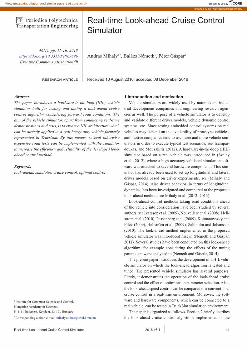
11Real-time Look-ahead Cruise Control Simulator 2018 46 1
AbstractThe paper introduces a hardware-in-the-loop (HIL) vehicle simulator built for testing and tuning a look-ahead cruise control algorithm considering forward road conditions. The aim of the vehicle simulator, apart from conducting real-time demonstrations and tests, is to create a HIL architecture which can be directly applied to a real heavy-duty vehicle formerly represented in TruckSim. By this means, several otherwise expensive road tests can be implemented with the simulator to increase the efficiency and reliability of the developed look-ahead control method.
Keywordslook-ahead, simulator, cruise control, optimal control
1 Introduction and motivationVehicle simulators are widely used by automakers, indus-
trial development companies and engineering research agen-cies as well. The purpose of a vehicle simulator is to develop and validate different driver models, vehicle dynamic control systems, etc. Since testing embedded control systems on real vehicles may depend on the availability of prototype vehicles, automotive companies tend to use more and more vehicle sim-ulators in order to execute typical test scenarios, see Tsampar-doukas, and Mouzakitis (2012). A hardware-in-the-loop (HIL) simulator based on a real vehicle was introduced in (Szalay et al., 2012), where a high-accuracy validated simulation soft-ware was attached to several hardware components. This sim-ulator has already been used to set up longitudinal and lateral driver models based on driver experiments, see (Mihály and Gáspár, 2014). Also driver behavior, in terms of longitudinal dynamics, has been investigated and compared to the proposed look-ahead method, see Mihály et al. (2012; 2013).
Look-ahead control methods taking road conditions ahead of the vehicle into consideration have been studied by several authors, see Ivarsson et al. (2009), Nouveliere et al. (2008), Hell-ström et al. (2010), Passenberg et al. (2009), Kolmanovszky and Filev (2009), Hellström et al. (2009), Sahlholm and Johansson (2010). The look-ahead method implemented in the proposed vehicle simulator was introduced first in (Németh and Gáspár, 2011). Several studies have been conducted on this look-ahead algorithm, for example considering the effects of the tuning parameters were analyzed in (Németh and Gáspár, 2014).
The present paper introduces the development of a HIL vehi-cle simulator on which the look-ahead algorithm is tested and tuned. The presented vehicle simulator has several purposes. Firstly, it demonstrates the operation of the look-ahead cruise control and the effect of optimization parameter selection. Also, the look-ahead speed control can be compared to a conventional cruise control in a real-time environment. Moreover, the soft-ware and hardware components, which can be connected to a real vehicle, can be tested in TruckSim simulation environment.
The paper is organized as follows. Section 2 briefly decribes the look-ahead cruise control algorithm implemented in the
1 Institute for Computer Science and Control, Hungarian Academy of Sciences, H-1111 Budapest, Kende u. 13-17., Hungary* Corresponding author, e-mail: [email protected]
46(1), pp. 11-16, 2018https://doi.org/10.3311/PPtr.9896Creative Commons Attribution b
research article
PP Periodica PolytechnicaTransportation Engineering
Real-time Look-ahead Cruise Control Simulator
András Mihály1*, Balázs Németh1, Péter Gáspár1
Received 16 August 2016; accepted 08 December 2016
brought to you by COREView metadata, citation and similar papers at core.ac.uk
provided by SZTAKI Publication Repository

12 Period. Polytech. Transp. Eng. A. Mihály, B. Németh, P. Gáspár
simulator. Sections 3 introduces the logical and physical archi-tecture of the complete HIL simulator with all of the hardware components involved. Section 4 deals with the high-fidelity TruckSim/Simulink real-time vehicle simulation environment, the linearized vehicle model, the speed controller design and shows the possible different driving modes. Finally, some con-cluding remarks are presented in Section 5.
2 Look-ahead control algorithmThe optimal velocity calculation for given road characteris-
tics has already been introduced in (Németh and Gáspár, 2013), thus here only a short description is given. The look-ahead dis-tance is divided into n number of sections as depicted in Fig. 1.
0 4321 5 6 n
vref0 vref1
original reference velocities:vref2 vref3 vref4 vref5 vref6 vrefn
modified reference velocity:ξ̇0
α1
α1
α4
Fl1
s1 s2
s3
Fig. 1 Division of predicted road
Assuming that road slope angle and the speed limit are known at each endpoints, the optimal velocity can be calcu-lated as:
λ ϑ ξ α= − −( ) +( ).2 11 0s Q g sin
where
ϑ γ γ= + +
., ,
=,
==∑ ∑∑Qv v
ms Fref i ref i
i
n
i di r jj i
n
i
n
0
22
1 1
2
where si i ∈ [1, n] is the length of the road section (L = ∑si), vref , i is the speed limit at each section point, Fdi , r = mgsin αi is the disturbance force from road inclinations, Q and γi are weights for the current and look-ahead reference velocities given as: γ1 + γ2 + ... + γn + Q = 1.
Two optimization problems must be solved: the longitudi-nal control force and the deviation from the reference veloc-ity must be minimized. The two optimization criteria provide different solutions, hence a balance should be achieved. First, minimization of control force Fl1
2 → min can be achieved by solving the following quadratic optimization problem:
F Q Q Ql n n1
2
0 1 1
2
= ( ) + ( ) + + ( )( ) →β β γ β γ min
with the following constrains 0 1≤ , ≤Q i γ and Q i+ =∑γ 1. Second, the minimization of the speed differences from the
speed limits must be formulated as:
vref , − →0 0
ξ min
The optimal solution for the latter is selecting
Q = 1 and
i i nγ = , ∈ ,[ ]0 1 . The appropriate balance is set by two performance weights
R1 and R2 . Performance weight R1 (0 ≤ R1 ≤ 1) shows the importance of energy minimization, while performance weight R2 (0 ≤ R2 ≤ 1) is connected to the minimization of travel time, where R1 + R2 = 1. Hence, a balance between the optimizations tasks can be achieved by using the performance weights R1 and R2 as follows:
Q RQ R Q R Q= + = − −( )1 2 11 1
γ γ γ γi i i iR R R i n= + = ∈ ,..,{ }1 2 11
,
Note, that in order to increase computational efficiency an analytical solution is given for the look-ahead optimiza-tion algorithm. The flowchart of the look-ahead algorithm is depicted in Fig. 2. Here, the vehicle physical details are consid-ered as constant parameters, while the tuning parameters (look-ahead distance: L, performance weight: R1 , number of division points: n) are set by the driver as detailed in Section 3. These tuning parameters are the inputs for the optimization algorithm, which uses the vehicle actual position in the calculation of the disturbance forces. Note, that the algorithm cycle time depends on the n parameter set by the driver. The constraining is neces-sary, because MicroAutobox II has limited computing capacity.
The look-ahead control algorithm shown in Fig. 2 is evalu-ated as follows. First, the tuning parameters given by the driver and received from TruckSim are set. Next, the resistance forces Fdi i ∈ [1, n] depending on the angle of the road for each of the look-ahead segments are calculated, where n represents the number of division points and L stands for the total look-ahead distance. The next cycle calculates all of the longitudinal drive/brake forces Fli i ∈ [1, n] for each road segment, by which the reference velocities vref , i i ∈ [1, n] (speed limits) can be reached . If all of the longitudinal forces have the same sign, the absolute minimal value is chosen, else the longitudinal force is set to be zero. The optimal acceleration is then given by dividing the optimal control force with the vehicle mass, while the optimal velocity is finally calculated by integrating the optimal acceleration.
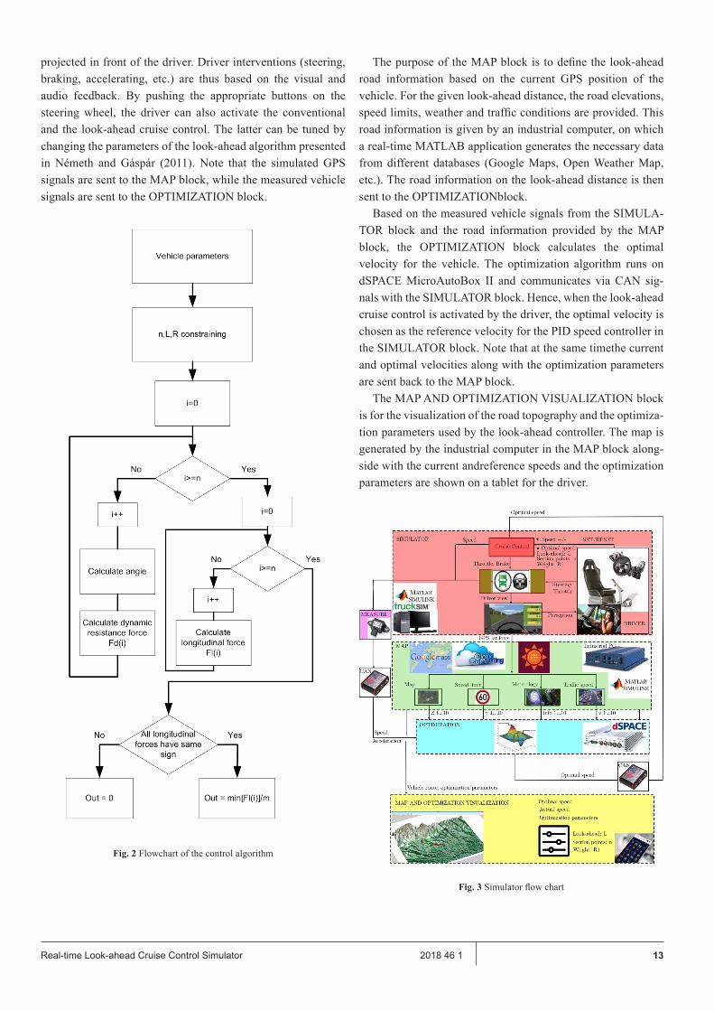
3 Architecture of the vehicle simulatorThe logical structure of the simulator is shown in Fig. 3.
The top SIMULATOR block includes the driver environment, which has the following hardware elements: a gaming steering wheel with force feedback, a pedal set and a gearbox appliedto a gaming driver seat, a projector used for visualization and a computer on which the real-time version of TruckSim soft-ware is running. The driver sits on the simulator seat operating the steering wheel and pedals, thus controlling the simulated vehicle in TruckSim. Hence, TruckSim generates the vehicle dynamics and the visualization of the environment, which is
(1)
(2)
(3)
(4)
(5b)
(5a)
13Real-time Look-ahead Cruise Control Simulator 2018 46 1
projected in front of the driver. Driver interventions (steering, braking, accelerating, etc.) are thus based on the visual and audio feedback. By pushing the appropriate buttons on the steering wheel, the driver can also activate the conventional and the look-ahead cruise control. The latter can be tuned by changing the parameters of the look-ahead algorithm presented in Németh and Gáspár (2011). Note that the simulated GPS signals are sent to the MAP block, while the measured vehicle signals are sent to the OPTIMIZATION block.
Fig. 2 Flowchart of the control algorithm
The purpose of the MAP block is to define the look-ahead road information based on the current GPS position of the vehicle. For the given look-ahead distance, the road elevations, speed limits, weather and traffic conditions are provided. This road information is given by an industrial computer, on which a real-time MATLAB application generates the necessary data from different databases (Google Maps, Open Weather Map, etc.). The road information on the look-ahead distance is then sent to the OPTIMIZATIONblock.
Based on the measured vehicle signals from the SIMULA-TOR block and the road information provided by the MAP block, the OPTIMIZATION block calculates the optimal velocity for the vehicle. The optimization algorithm runs on dSPACE MicroAutoBox II and communicates via CAN sig-nals with the SIMULATOR block. Hence, when the look-ahead cruise control is activated by the driver, the optimal velocity is chosen as the reference velocity for the PID speed controller in the SIMULATOR block. Note that at the same timethe current and optimal velocities along with the optimization parameters are sent back to the MAP block.
The MAP AND OPTIMIZATION VISUALIZATION block is for the visualization of the road topography and the optimiza-tion parameters used by the look-ahead controller. The map is generated by the industrial computer in the MAP block along-side with the current andreference speeds and the optimization parameters are shown on a tablet for the driver.
Fig. 3 Simulator flow chart

14 Period. Polytech. Transp. Eng. A. Mihály, B. Németh, P. Gáspár
The technical architecture of the simulator is shown in Fig. 4. The real-time TruckSim simulation running on the desktop com-puter generates the virtual GPS signals (longitude, latitude, alti-tude), which are sent to the industrial computer via RS-232 serial port. Note that in the real vehicle these signals are provided by the on-board GPS device. The desktop computer sends the veloc-ity and acceleration data to Microsoft dSPACE Autobox II via CAN messages, which are handled by a CANcaseXL card built in the desktop computer. The industrial computer is connected via Ethernet and WiFi Router to the internet databases (Google Maps)and sends the predicted road information to the Microsoft dSPACE Autobox II via RS-232 serial port. The current and opti-mal velocities, the road map and the optimization parameters are sent to a tablet application via WiFi communciation. Note that in the technical architecture shown in Fig. 4 it is clearly visible how the hardware components can be isolated from the vehicle simulator and installed on a real vehicle.
Fig. 4 Simulator technical architetcure
4 Real-time TruckSim simulator4.1 Simulation environment
The real-time version of TruckSim software is used for the vehicle simulations and it contains high complexity models of trucks, lorries, buses and other heavy-duty vehicles. TruckSim contains several validated models of powertrains, braking sys-tems, steering systems, wheels, etc. TruckSim also creates a package consisting of multiple files based on a set of vehicle parameters, traffic environment, weather parameters, which are passed to MATLAB. The Simulink model file contains an S-function block, which receives the file package from Truck-Sim and runs the S-functions related to the simulated vehicle. Thus, the simulation can be run with the file package gener-ated by TruckSim, while a real-time animation of the vehicle motion is produced.
The simulation environment is shown in Fig. 5. The road inclinations and curves are defined in TruckSim based on real data provided by different databases. The driver sitting in the
driver seat operates the gaming steering wheel and defines the inputs based on the visual perception. Note that when thecruise control (conventional or look-ahead) is switched on, only steer-ing input is needed from the driver. TruckSim/Simulink gener-ates the vehicle dynamics and the visualization of the simula-tion. Here, a conventional two-axle tour bus is simulated with a 150 kW engine, 5 speed automatic transmission.
Fig. 5 Real-time simulation with TruckSim
4.2 Vehicle modelFor the longitudinal control of the simulated vehicle a sim-
plified vehicle model is introduced. Since the output of PI speed controller is a positive or negative longitudinal force, the low-level controllers must address the corresponding physical actu-ators (see Fig. 6). Thus, for setting the desired acceleration the throttle angle of the engine must be adjusted, while for braking the brake pressure must be set. Hence, by linearizing the vehi-cle model around the operation points, the actuator inputs can be defined accurately to meet the desired acceleration given by the reference longitudinal force of the speed controller.
Fig. 6 Vehicle model
4.3 Design of PI speed controllerThe PI speed controller has been tuned by simulations for a
specific vehicle in the following steps: Requirement definition: minimum overshoot and steady-
state error, minimal value of regulatory power. During the PI control design a feedback linearization method
has been applied, as already introduced in (Mayr, 1994). Thus,

15Real-time Look-ahead Cruise Control Simulator 2018 46 1
the highly non-linear components of the vehicle dynamics (aerodynamic drag, road slope resistance, rolling resistance) are calculated by using measurement data. These non-linear resistance forces are added to those provided by the speed con-troller. The method has the advantage that by separating the calculated nonlinearities a simple linear PID controller can be realized for the highly non-linear system.
The feedback linearized PI speed controller and the vehicle model have been created in MATLAB/Simulink and connected to TruckSim environment (see Fig. 7). A predefined hilly route has been provided with a jump in the reference speed signal. Also, a performance function has been defined as a weighted (Q,R) amount of the square integral, the longitudinal force and the velocity tracking error.
The simulation is run by calling a MATLAB function. For a given performance weighting Q and R related to the impor-tance of velocity tracking error minimization or longitudinal control force minimization, an optimization routine is called and the TruckSim simulation is run with the given value of P and I parameters. The TruckSim simulation is run cyclically while P and I parameters are altered until the previously defined performance function is minimized. Hence, by the appropriate selection of Q and R weightings, the PI controller can be tuned to guarantee both minimal overshooting and steady state error while the control force is kept small.
Note that in the performance weighing selection (Q,R) in the controller tuning process listed above, engineering and practi-cal considerations are used.
Fig. 7 Speed controller design
4.4 Simulation modesThe vehicle simulator can be driven in three different driv-
ing modes, which can be selected by pushing different buttons on the steering wheel.
When the real-time simulation starts, the vehicle can be driven manually with the manipulation of the steering wheel and the brake/accelerator pedals (see Fig. 8(a)). In this mode, the speed of the vehicle only depends on the driver’s intention and vehicle capability.
By pushing the SET/RESET button the conventional cruise control detailed in Section 3 is activated and the current speed of the vehicle is set as the reference velocity (see Fig. 8(b)). Note
that this reference velocity can be incremented/decremented with 1km/h steps by pulling the paddles behind the steering wheel. In this driving mode, only steering intervention is required by the driver while the vehicle generally follows the speed limit.
Finally, by pushing the OPTIMAL button on the steering wheel the look-ahead cruise control is activated (see Fig. 8(c)). In this mode, based on the given road information (speed lim-its, road inclinations) the bus follows an optimal velocity pro-file with the consideration of both energy and traveling time minimization. Note that on the gearbox console further buttons
(a) Conventional driving mode
S D
(b) Conventional cruise control mode
(c) Look-ahead cruise control mode
Fig. 8 Simulator driving modes

16 Period. Polytech. Transp. Eng. A. Mihály, B. Németh, P. Gáspár
are selected for tuning the look-ahead algorithm in real-time driving mode. Hence, with gearbox console buttons the look-ahead distance L ∈ [0,5000] can be modified by 550 m steps, the number of look-ahead section points n ∈ [0,100] can be incremented/decremented with 10 steps, while the optimization parameter R1 ∈ [0,1] can also be modified by 0.1 steps. Note, that R1 + R2 = 1 implies that defining optimization parameter R1 also determines R2 , since R2 = 1 − R1 . In this driving mode only steering intervention is needed by the driver while the effect of look-ahead parameter tuning can be tested in realtime.
5 ConclusionIn the paper a real-time HIL driving simulator has been pre-
sented with the aim of testing and tuning a look-ahead cruise controller. The simulator has been built in such a way that the hardware components can easily be isolated from the real-time TruckSim simulation environment and installed on a real vehi-cle for road testing. The vehicle modeling and speed control design have been described, as well as the different driving modes provided by the simulator. The main contribution of the HIL simulator is that the look-ahead controller can be tested and tuned in a real-time environment.
AcknowledgmentThe research was supported by the National Research,
Development and Innovation Fund through the project „SEP-PAC: Safety and Economic Platform for Partially Automated Commercial vehicles” (VKSZ 14-1-2015-0125). This paper was partially supported by the János Bolyai Research Scholar-ship of the Hungarian Academy of Sciences.
ReferencesHellström, E., Ẳslund, J., Nielsen, L. (2010). Horizon length and fuel equivalents
for fuel-optimal look-ahead control. In: 6th IFAC Symposium Advances in Automatic Control. IFAC Proceedings Volumes. 43(7), pp. 360-368.
https://doi.org/10.3182/20100712-3-DE-2013.00114Hellström, E., Ivarsson, M., Ẳslund, J., Nielsen, L. (2009). Look-ahead control
for heavy trucks to minimize trip time and fuel consumption. Control Engineering Practice. 17(2), pp. 245–254.
https://doi.org/10.1016/j.conengprac.2008.07.005Ivarsson, M., Ẳslund, J., Nielsen, L. (2009). Look ahead control - consequenc-
es of a non-linear fuel map on truck fuel consumption. Proceedings of the Institution of Mechanical Engineers, Part D, Journal of Automobile Engineering. 223(10), pp. 1223–1238.
https://doi.org/10.1243%2F09544070JAUTO1131Kolmanovsky, I. V., Filev, D. P. (2009). Stochastic optimal control of systems
with soft constraints and opportunities for automotive applications. In: 18th IEEEConference on Control Applications. Part of 2009 IEEE Multi-conference on Systems and Control. Saint Petersburgh, Russia, Jul. 8-10, 2009, pp. 1265-1270.
https://doi.org/10.1109/CCA.2009.5280822
Mayr, R. (1994). Intelligent cruisec on trol for vehicles based on feedback lin-earization. In: Proceedings of the 1994 American Control Conference, 1, pp. 16–20
https://doi.org/10.1109/ACC.1994.751684Mihály, A., Gáspár, P. (2014). Identification of a linear driver modelbased on
simulator experiments. 2014 IEEE 9th International Symposium on Ap-plied Computational Intelligence and Informatics. Timisoara,Romania, May 15-17. pp. 13-18. https://doi.org/10.1109/SACI.2014.6840057
Mihály, A., Németh, B., Gáspár, P. (2012). Analysis of driver behavior related to look-ahead control. IFAC Proceedings Volumes. 45(24), pp. 268-273. https://doi.org/10.3182/20120912-3-BG-2031.00056
Mihály, A., Németh, B., Gáspár, P. (2013). Enhancement of driver speed based on multi-criteria optimization. Periodica Polytechnica Transportation Engineering. 41(1), pp. 71-76.
https://doi.org/10.3311/PPtr.7103Németh, B., Gáspár, P. (2011). Road inclination sin the design of LPV-based
adaptive cruise control. In: Proceedings of 18th IFAC World Congress. Milano, Italy, Aug. 28-Sep. 02, 2011, pp. 2202-2207.
https://doi.org/10.3182/20110828-6-IT-1002.00932Németh, B., Gáspár, P. (2013). Design of vehicle cruise control using road in-
clinations. International Journal of Vehicle Autonomous Systems. 11(4), pp. 313–333.
https://doi.org/10.1504/IJVAS.2013.056651Németh, B., Gáspár, P. (2014). Model-based sensitivity analysis of the look-
ahead cruise control. In: 15th IEEE International Symposium on Com-putational Intelligence and Informatics. Budapest, Hungary. Nov. 19-21. 2014. pp. 103-108.
https://doi.org/10.1109/CINTI.2014.7028657Nouveliere, L., Braci, M., Menhour, L., Luu, H. T., Mammar, S. (2008). Fuel
consumption optimization for a city bus. In: UKACC Control Conference.Passenberg, B., Kock, P., Stursberg, O. (2009). Combined time and fuel opti-
mal driving of trucks based on a hybridmodel. In: 2009 European Con-trol Conference Budapest, Hungary. Aug. 23-26. 2009. pp. 4955-4960.
Sahlholm, P., Johansson, K. H. (2010). Road grade estimation for look-ahead measurement runs. Control Engineering Practice. 19(11), pp. 1328-1341.
https://doi.org/10.1016/j.conengprac.2009.09.007Szalay, Z., Gáspár, P., Kánya, Z., Nagy. D. (2012). Development of vehicle
simulator based on a real car for research and education purposes. In: Proceedingsof the FISITA 2012 World Automotive Congress. 196, pp. 1301–1312.
https://doi.org/ 10.1007/978-3-642-33738-3_31Tsampardoukas, G., Mouzakitis, A. (2012). Deployment of full vehicles im-
ulator for electrical control system validation. In: Proceedings of 2012 UKACC International Conference on Control. pp. 551–556.
https://doi.org/10.1109/CONTROL.2012.6334689