Embed Size (px)
Citation preview
REAL TIME DATA ACQUISITION SYSTEM FOR HIGH ALTITUDE BALLOON
LAUNCH AT ADLER PLANETERIUM-A FAR HORIZONS PROJECT
Vidya Gopalakrishnan (A20249496)
Chaitanya Erande (A20249250)
Department of Electrical Engineering
Illinois Institute of Technology
Abstract – High Altitude balloon launches are
experimental projects undertaken by students, volunteers
or amateur astronomers so as to engage in understanding
of near space using mathematics science and technology.
Most of the circuits for the onboard experimental setups
are which hand crafted or off the shelf hence the projects
have come to be termed as the “ poor mans space
program”. Chicago’s Adler Planetarium, the first
planetarium in the United States of America , gives such
an opportunity through the Far Horizons project ,
helping students and volunteers to work side by side with
the planetariums’ astronomy faculty .The requirement for
Adler Far Horizons project is to design a wireless
communication system to have real time data acquisition
of the data collected by the experiments ,launched in many
of its high altitude balloon launches . This paper gives a
detailed report on the high level design requirements, link
budget analysis, transceiver selection, antenna
considerations and interfacing requirements of this
wireless data communication system design.
Index Terms— Ham Radio, IF Filter, J-pole Antenna
Micro strip Patch Antenna ,Yagi-Uda Antenna, Parabolic
Reflector Antenna
1. INTRODUCTION-FAR HORIZONS OFADLER
PLANETERIUM
Far Horizons is a Backend Research Division of Chicago
Adler Planetarium. Interns, high schools students and
volunteers get hands on experience in designing, executing
and testing live project. These projects include sending
experimental payloads to the edge for space by using high
altitude balloons. These balloons go as high as 100,000 feet an
collects very informative data such pressure temperature as
well as reading of photons in the upper atmosphere. The
circuits for the experimental setups are hand crafted by the
students and/or volunteers thus making this a highly
informative experience.
The process of launching balloon from start to finish is as
follows. Experimental Setups which are to be send with the
payload are as explained , designed and tested in the Far
Horizons lab .The tested setups are launched using a balloon
into the upper atmosphere from a suitable location .The
balloon used for these launches are filled with helium for
liftoffs. These balloons reach altitudes of 100000 feet and are
hence called Near Space Projects. The balloon is tracked
throughout its flight using a GPS tracker that sends beacons
every two minutes, with the exact latitude and longitude
coordinates of the balloon.
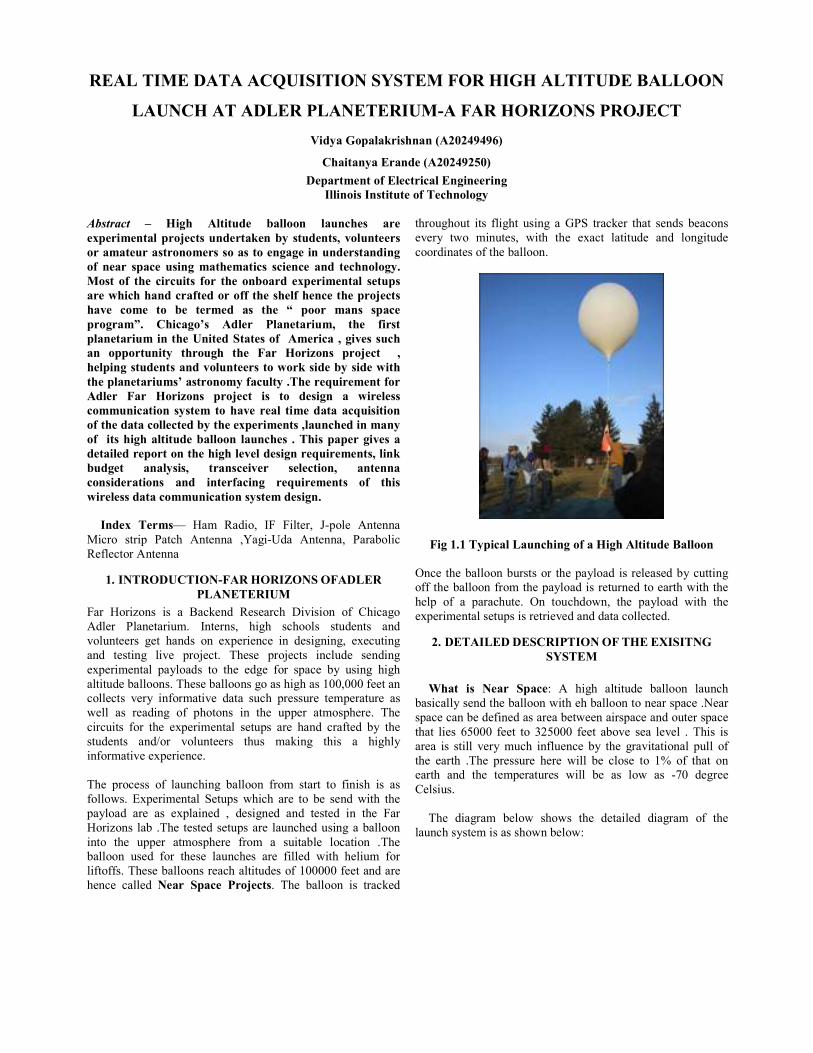
Fig 1.1 Typical Launching of a High Altitude Balloon
Once the balloon bursts or the payload is released by cutting
off the balloon from the payload is returned to earth with the
help of a parachute. On touchdown, the payload with the
experimental setups is retrieved and data collected.
2. DETAILED DESCRIPTION OF THE EXISITNG
SYSTEM
What is Near Space: A high altitude balloon launch
basically send the balloon with eh balloon to near space .Near
space can be defined as area between airspace and outer space
that lies 65000 feet to 325000 feet above sea level . This is
area is still very much influence by the gravitational pull of
the earth .The pressure here will be close to 1% of that on
earth and the temperatures will be as low as -70 degree
Celsius.
The diagram below shows the detailed diagram of the
launch system is as shown below:

Fig 2.1 High Altitude Balloon Components
Balloon: The balloon is made highly flexible latex material
and itself provides the lift that is required when it is filled with
helium. The balloon can reach heights of up to 100,000 feet
until it burst due to pressure differences.
Recovery System: The parachutes that are used for the
recovery of the payload come with a loop seen at the apex to
which the payload is attached.
Payloads: Payloads consists of experimental setups such as
pressure sensor, temperature sensor, Geiger counter etc which
is used to take measurements in the upper atmosphere. These
retrieve highly valuable data. But this data is currently stored
on to an EEPROM or a USB stick and can only been accessed
once the payload is retrieved
GPS System: There are two GPS [Global Positioning System]
trackers that are launched along with the payloads. These GPS
trackers send APRS[Automatic Packet Reporting System]
tracking data to Receiver which will be in a van which will be
used to track the balloon. Currently this van according to the
GPS data will chase the balloon throughout its flight to
retrieve the payload as soon as it has landed. The GPS tracker
system works in the two meter band which covers the 144.000
to 148.000 Mhz. Smart beaconing can also be enabled in this
system for periodic operation and this is what is used by Far
Horizons to receive the regular APRS data from the balloon
once its launched. In addition to the APRS data the GPRS
data also provides NMEA strings. These strings can be used
to design a balloon release or cut down system based on
distance or altitude The GPS system currently used by Adler
is from Big Red BEE and is shown below.
Fig 2.2 GPS System Used By Far Horizons
Camera: A camera is also launched along with the
experimental payloads with the high altitude system to take
pictures or video of the scend as well as descend of the
balloon. Video and photographs retrieved from this system is
highly educational as well as very beautiful .The still cameras
are timed to take pictures every five seconds.
Cut down System: Every high altitude balloon launch has an
emergency cut down system to release the balloon. This cut
down system is currently triggered based on time. When
triggered the cut down system discharges a small electrical
current which melts a nichrome wire. This wire is connected
to a string which is attached to the balloon hence release the
balloon when the string burns. The cut down system can also
triggered based on distance or altitude.
Microcontrollers, A/D convertors and EEPROMS:
Microcontrollers known as Basic Stamp II is used for all the
programming purposes such as taking measurements from
pressure sensor, temperature sensor as well as triggering the
cut down system. The A/ D[Analogue to Digital] convertor is
used to convert the analog pressure and temperature readings
to digital data which is then stored in the EEPROM
Helium Balloon
Parachute
Payload 1
Payload 2
GPS Tracker 1
GPS Tracker 2
Cut Down String

Fig 2.3 Basic Stamp II – MCU used in experimental
Setups
Restrictions By FAA: The FAA [Federal Aviation
Administration] Regulations state that the entire payload
including the camera, experimental circuits and the parachute
which is used for the descend once the balloon has released
should not weigh more than 12 pounds.
Restrictions by FCC: According to the FCC [Federal
Communication Commission] regulations, amateur balloon
launches from high altitude can transmit not more than 19.2
kbps. Hence for the time being the proposed bandwidth is not
more than 19.2 kbps. The idea is to transmit small amounts of
data or snapshots from the onboard camera.
2.1. Requirements By Far Horizons
All the data collected by the payload and a lot he photographs
taken by the camera are currently stored in EEPROMS,USB
sticks and memory sticks .The data collected can only be
retrieved when the payload have been recovered . The
requirements of Far Horizon was to explore the possibility of
a real time data acquisition system .The communication
system design will be done in stages consisting of :
a). Stage 1: High Level Design of the Real Time Data
Acquisition System including link budget analysis , frequency
selection, transceiver option, suitable antenna.
b), Stage 2: Design of data collection and interface system to
the communication system .
c). Stage 3: Implementation of the downlink Communication
System
d). Stage 4: Implementation of uplink communication system
This paper details the Stage 1 of the project. This paper will
also have a brief description into the calculations and
interfacing requirements in Stage 2.
3. HIGH LEVEL DESIGN OF THE COMMUNICATION
SYSTEM
Fig 3.1Communication System Block Diagram – Balloon
Station
A wireless live data acquisition system will make the data
acquiring a real time process. This can also make control for
some of the systems a lot easier like the cut down.
Fig 3.1 Communication System Block Diagram –
Mobile/Ground Station
Data Interfacing System
To laptop/ PC
Transmitter/Receiver
System
Preamplifier
RECEIVER ANTENNAS YAGI UDA OR
PARABOLIC REFLECTOR
Experimental Payload-1
Experimental Payload -2
Microcontroller Unit-1
Microcontroller Unit-2
Data Arbitration/Interfacing
System
Transmitter/Receiver
System
RS232
Camera
J-POLE/PATCH
ANTENNAS AT
433MHZ
Serial
Connection
to collect
Data

The proposed system is as follows:
1).The frequency considered for uplink and downlink is in the
70cm band range between 430 to 440 MHz. This is in the
Amateur Radio Frequency Band and the operator will require
a license to use the equipments transmitting an receiving in
this frequency
2). There will be a 2 /MHz difference between the uplink and
the downlink
3). The proposed modulation for this system is FSK
[frequency shift keying].
4). The data will be connected on to a EEPROM using a
suitable MCU[Micro Controller Unit] that will programmed
to be capable of arbitrating data from various experimental
setup as well as from an onboard camera .
5). This will be a line of sight communication system with a
vertical distance of about 100000 feet and max horizontal
distance of not less than 5 miles but not more than 20 miles at
a time .This horizontal distance is so less because the
receiving system will be currently mobile van chasing the
balloon . The maximum of 20 miles occurs when the ball0on
has already been launched, and due to the time taken by the
team to pack the equipments and board the chase van .
4. FREQUENCY SELECTION
Two Frequency bands were considered when selecting the
appropriate frequency for this project.
ISM Frequency Bands: The ISM [Industrial, Scientific or
Medical] band also known as the unlicensed band as most of
the users in the frequency band must be tolerant of other
frequencies which might cause interference from other ISM
equipments. .WDCT is one of the well known examples of
applications and equipments using ISM band in the 2.4GHz
range. According to the ITU [International
Telecommunication Union] - R these bands include:
Frequency
Range (HZ)
Center
Frequency(Hz) Availability
6.765 – 6.795
MHz 6.78 MHz
Subject to local
Acceptance
13.553 - 13.567
MHz 13.560 MHz
26.957 - 27.283
MHz 27.120 MHz
40.66 - 40.70
MHz 40.68 MHz
433.05 -434.79
MHz 433.92MHz
Region1 only and
subject to local
acceptance
902 - 928 MHz 915 MHz Region 2 only
2.400 - 2.500
GHz 2.450 GHz
5.725 - 5.875
GHz 5.800 GHz
24 -24.25 GHz 24.125 GHz
61-61.5 GHz 61.25 GHz
Subject to local
Acceptance
122 -123 GHz 122.5 GHz
Subject to local
Acceptance
244 -246 GHz 245 GHz
Subject to local
Acceptance
Table 4.1 ISM Bands [10]
HAM Radio Frequency Bands: Used by amateur radio
enthusiasts for recreation, experimentation, training and
communication in case of emergencies. To use any of the
frequencies allocated for this band a special license is required
by the user. To acquire this license a test is taken by the Ham
radio specialists. Amateur Radio Frequency bands are
allocated ITU .ITU sets aside a part of every spectrum for
Ham radios .ITU also regulates the technical and operational
characteristics in HAM radio bands. This is done by dividing
the world into regions .Each Region ahs its own allocated set
of frequencies in for HAM radio specialists’ .United Stated of
America lies in ITU regions 2 and the table for the allocation
of these license are shown below:
Frequencies (MHz)
ITU band Band name Lower
end
Upper
end
5 – LF 2200 meters 135.7 kHz 137.8 kHz
6 – MF 160 meters 1.8 2
80 meters 3.5 4
60 meters
Channelized - 5.332,
5.348, 5.368, 5.373,
5.405 (USB only)
40 meters 7 7.3
30 meters 10.1 10.15
20 meters 14 14.35
17 meters 18.068 18.168
15 meters 21 21.45
12 meters 24.89 24.99
7 – HF 10 meters 28 29.7
6 meters 50 54
2 meters 144 148
219 220
8 – VHF 1.25 meters 222 225
70
centimeters 420 450
33
centimeters 902 928
23
centimeters 1240 1300
2300 2310
9 – UHF
13
centimeters 2390 2450

9
centimeters 3300 3500
5
centimeters 5650 5925
3
centimeters 10000 10500
10 – SHF
1.2
centimeters 24000 24250
6
millimeters 47000 47200
4
millimeters 75500 81000
2.5
millimeters 119980 120020
2
millimeters 142000 149000
11 – EHF 1 millimeter 241000 250000
Table 4.2 ITU Region2 HAM Frequency Bands [11]
433MHz used for this project lies in the 70 cm UHF
frequency band of the Amateur Radio allocated for the ITU
Region 2.
Choice of 70cm Frequency Band: The frequency
allocation in the 70 cm radio band for Ham radio lies from
420MHz to 450MHz .70 cm band propagation characteristics
that works to its advantage include penetration through
buildings, low noise floor and good tolerance to natural and
artificial interference .70 cm band is the lowest frequency and
in which ionospheric reflection is observed .It is greatly
helped by reflections from buildings, airplanes etc..
Topospheric refraction also helps to extend the range of the
signal of this frequency.
5. LINK BUDGET ANALYSIS
Link budget calculation is primary analysis required while
designing the wireless system Analysis helps to determine the
feasibility of the entire system .It also give a heads up on the
tradeoffs required to obtain the a complete working system as
per the given cost budget and the requirements of the
customers .Suitable data rate , effects of range and the
modulation methods as well as how they will effect the
system can also be determined by this simple calculation .The
factors that will come into consideration while determining
the link budget will be permitted output power, output power
of the transmitter ,antenna gains, free space loss, fading if any,
receiver sensitivity , signal to noise ratio, environmental
conditions etc .The link budget formula is given below :
Received Power (dBm) = Transmitted Power (dBm) +
Gains (dB) − Losses (dB)
Formula 5.1 Link Budget Formula
For the High Altitude balloon communication system the
following parameter were considered for the link budget
analysis:
1). Transmitter Output Power
2).Gain of the Transmitter Antenna
3).Free space Loss
4). Gain of the Receiver Antenna
4). Receiver Sensitivity
This basically gives the relationship between the output power
of the transmitter and the power of the signal at the receiving
antennas. This being a line of sight radio system the most
prominent loss to expect for this communication will be the
FSPL [Free Space Path Loss] .
FSPL is proportional to the square of the distance between the
transmitter and the receiver and also proportional to the
square of the frequency of the radio signal. In the case of the
balloon communication the distance considered will be the
slant distance as shown in the figures below. This is called the
slant distance calculated using Pythagoras theorem and has
been used for calculating FSPL.
Fig 5.1 Distance Calculation for FSPL
Large number transceivers were considered in the range of
433MHZ to use for this project which had power levels in the
range in 10mW.The link budget calculations have been given
in the Appendix [1] of the report for reference. From the link
budget analysis shown in Appendix [1] it can be observed that
there will be a requirement of an amplifier at the transmitter
side to boost the signal before sending it. But FAA regulations
clearly states that the payload(s) should not exceed more than
12 pounds for a balloon launch. In order to solve this problem
it was decided to add a preamplifier at the receiver the link
budget analysis after addition of the preamplifier
Appendix[ 2] .Please Refer Appendix [1] and Appendix [2]
for link budget analysis and clarification on requirements of
preamplifier
FSPL FORMULA = (λ/4πd)^2
Slant Distance = 31524 m
8024m
30480m

6. TRANSCEIVER SPECIFICATIONS
The transceiver chosen for the communication system come
from a large range of TI [Texas Instruments] sub 1GHz
transmitters. This transceiver generally used for ISM and SRD
(Short Range Distance) applications also has the 433 MHZ
ham band frequency that has been chosen for this project .The
transmitter which allows this range is the CC1101 from TI.
The transmitter pair also comes with the development kit and
is known as the CC1101DK433 :
Fig 6.1 CC1101DK433-Development Kit
The advantages of CC1101 transmitter over its predecessors
are as follows as quoted from the user manual are as follows:
• Improved spurious response
• Better close-in phase noise thus improved Adjacent
Channel Power (ACP) performance
• Higher input saturation level
• Improved output power ramping
• Extended frequency bands of operation in the case of
CC1101 387-464MHz and 779 – 928MHz
The transceiver comes with a built in baseband modem which
supports various kinds modulation basically in FSK ,The
transmitter FIFO[First In First Out] and 64 byte transmitter/
receiver pair can be controlled using an SPI interface . The
circuit n diagram of the CC1101 with a few external
components is as shown below. The CC1101 can also be used
in conjunction with a MCU such as a basic stamp II, Arduino
or PIC32 for data input and arbitration between various.
Performance Features of CC1101 Transceiver:
The RF performance features of the TI CC1101 are as follows:
• -116dbm with a 1% error rate at 0.6kBaud at 433
MHz
• Programmable output power at +12dbm
• Programmable data rate up to 0.6 to 600kbaud
• The digital channel filter bandwidth ranges from 58
to 812 KHz
• Low Power consumption
The Integrated modulator Features are:
• Supports 2-FSK, 4-FSK, GFSK, and MSK
• AFC can be used to align the frequency synthesizer
to the received signal centre frequency
• Integrated analog temperature sensor
Low Power Consumption Features:
• 200nA sleep mode feature; while 200 microseconds
from sleep mode to RX or TX operations as required
• Separate 64 byte RX/TX data FIFO
• The operating temperature of the transceiver lies
between -40 to 85 degree Celsius
At 433MHZ the data transfer characteristics is as given below:
• 0.6 k Baud data rate, Receiver sensitivity -116
dbm
• 1.2 k Baud data rate, Receiver Sensitivity -112dbM
• 38.4 k Baud data rate, Receiver Sensitivity -
104dbm
• 250 k Baud data rate, Receiver sensitivity -95 dbm
Fig 6.2 Block Diagram of CC1101
Working Characteristics of CC1101:
As shown in the block diagram above ,CC1101 has a low
IF[Intermediate Frequency]-receiver .The signal received
from he preamplifier will be amplified by the LNA[Low
Noise Amplifier] and down converted to IF to be used by the
IF receiver of CC1101.AGC, filter channelling and
demodulation / synchronization of bits are all digitally
performed by CC1101.

In the transmitter part the frequency is directly synchronised
by the frequency synthesizer. The reference frequency of the
synthesizer is obtained from the crystal oscillator .The digital
baseband includes support for channel configuration, packet
handling and data buffering.
Fig 6.3 Application Circuit of 433MHzCC1101
Receiver Sensitivity, Bandwidth and Baud rates:
When looking at the link budget analysis in the parameter of
the receiver is given as follows.
Receiver Characteristic: 0.6kbaud data rate, GFSK, 14.3 KHz deviation, 58 KHz digital filter bandwidth
These parameters say that the bandwidth of the digital filter
used to transmit the 0.6 kbaud is about 58 kHz. That is a very
large bandwidth transfer such small amount of data and will
reduce the SNR of the receiver. But the deviation of the
central frequency is given as 14.3 KHz. This states that the
central frequency fluctuates between 14.3 KHz and -
14.3KHZ .This means that receiver sensitivity fluctuates
between these frequencies at 58 KHz bandwidth. It’s due to
this deviation that the bandwidth used to transfer such a small
amount of data is about 58 KHz
7. ANTENNA CONSIDERATIONS
A communication is not complete with out an antenna system,
which converts electrical signal to RF electromagnetic waves
at the transmitter end propagates through free space. At the
receiver end it converts these RF signal to electrical signals.
Considering the fact that the balloon position and direction
cannot be predicted the use of a directional antenna will not
serve the purpose at the balloon .An Omni directional antenna
with an ground plane will be appropriate for the high altitude
balloon .Ground plane is an electrically conductive surface
that allow an antenna to function properly .But the receiver
antenna can be highly directive antenna like a yagi antenna
or a parabolic reflector type antenna ,which will point to the
approximate direction of the balloon .The factors of the
antenna that has to be considered is radiation pattern,
polarization and impedance matching ,
Two types of antennas have been considered which will be
mounted on the balloon:
1).J-pole antenna
2).Patch antenna
J-pole Antenna:
A J-pole antenna is the first antenna to be considered for this
project because of its almost Omni-directional radiation
pattern and integrated ground plane This antennas were
invented by the Germans for use with light weight air balloons
and is currently very popular with amateur radio
operators .This antenna is very simple to construct .There are
a number advantages over the usual normal vertical antennas.
Another attributes of this antenna that are very important are
that this antenna does not require radials and also provides
more gain than normal antennas over a quarter wave
vertical .This antenna is ideally suited for VHF and above .
J-pole antenna is normally end fed .The J-pole antenna is end
fed using a quarter wave stub of open wire or 300 ohm
balance feeder to match the impedance of a normal 50 ohm
coaxial cable which will be connected to the transmitting
device. The polarization of this antenna is vertical .For a
433MHZ J-pole antenna the dimensions will be:
The J-pole antenna consists the parts show below and along
with it are the dimensions of a 433MHz J-pole antenna
A -a long radiating element -19.54 inches
B- a short stub element – 6.48 inches
C- Distance to feed connections – 0.64 inches
D- Distance between elements – 0.61 inches
Fig 7.1 Dimensions of 433MHz J-pole antenna
The radiation pattern of the J-pole antenna is as shown below.

Fig 7.2 Radiation Pattern of J-pole Antenna
This antenna gives an approximate gain between 2.5 to 3 dBi.
The disadvantages of this antenna can be noticed from tis
radiation pattern. Even if this antenna is Omni-directional this
antenna has a vertical polarization. This makes null right
below the antenna. At the time of ascend the transmitter
waves will not be propagated properly because of its null
directly below it. Another disadvantage is that even at 3db
gain the angle of orientation of this antenna will only transmit
the signal at an angle of 25 degrees would only be useful if
the transmitter is at a farther distance from the receiver.
Patch Antenna:
Due to some of the above mentioned disadvantages of j-pole
antennas, one more antenna is being considered for
communication from the balloon. This is the patch antenna.
This is a very low profile antenna but with many advantages
such as it is light weight inexpensive and very easy to
integrate .This antenna like the j-pole also has an integrated
ground plane. Another advantage of this antenna over the j-
pole antenna is that it can be vertically or horizontally
mounted .This is because the polarization is not effected like
that of a j-pole antenna when it is horizontally mounted.
Fig 7.3 Parts of Micro strip Patch Antenna
The drawing shown above gives brief description of the
architecture of the patch antenna. Simply put its flat plate over
a ground plane which is usually a PC Board .The centre
conductor of the coax serve as the feed of the antenna. This
couples the electromagnetic energy in and out of the
patch .The electromagnetic filed is zero at the centre of the
patch, maximum and minimum on either side.
Since the patch antenna can be mounted because the
polarization of it can be mounted horizontally at the bottom of
the balloon hence helping to better signal to ratio at 3db gain.
The radiation pattern of the patch antenna is as shown below
is much better than that of the j-pole. In a horizontal mount
the radiation pattern will have no null directly below and also
when the balloon in flight, it has an angular width of 69
degrees at a 3db gain.
Fig 7.4 Radiation Pattern of Micro-strip Patch Antenna
Receiver Antennas:
As explained before the antenna at the receiver side should be
a good directive antenna. A directive antenna can be used to
pick up weak RF signals by pointing it to the approximate
location of the balloon which can be easily determined by the
on board GPS system. The two antennas under consideration
for the receiver mobile or base station is the Yagi - Uda
antenna and the parabolic reflector type antenna. More
investigation on the most suitable type, impedance matching
between the transmitter and the receiver antennas etc are

required for complete fool proof design of the communication
system.
8. BRIEF INTRODUCTION AND CHALLENGES ON
INTERFACING THE COMMUNICATION SYSTEM-
STAGE 2
As explained earlier the paper, the project is divided into
stages and above gives a detailed explanation of the Stage 1 –
proposal and design of the Communication System. The
second stage of the project is interfacing this communication
system with the already existing experimental setups and the
camera.
Camera Interfacing System:
A brief calculation of the bit rate, data transfer rate, buffering
requirements were performed assuming the communication of
transferring only still images from an RS232 camera. Below
shown is a brief block diagram of the Camera Interfacing
System:
Fig 8.1 Assumed Block Diagram for Camera Interfacing
The formatting of the images taken by the camera was
assumed to be 640 x 480 with a 40% compression. This
compression and images size was assumed so that images will
be comparatively good quality. Currently, the camera on
board the high altitude balloon is set to take images every 5
seconds. The images will be transferred from the camera to a
MCU using a UART [Universal Asynchronous Transmitter
Receiver]. From the camera specification, the camera can
transfer a single image at 115.2kbps to the MCU. MCU will
be used to store these images. At this compression the entire
images will be about 23Kbytes which is about 184kbits per
image.
As per the FCC regulations, an amateur wireless system
cannot transfer at more than 19.2 kbps. Thus the image cannot
be transferred in one go between the transmitter and the
receiver station even the transceiver is capable of high data
rates at the expense of receiver sensitivity. There will have to
be buffering mechanism either at the MCU or at the
transceiver. Assuming that the MCU is programmed to buffer
and send the images at 19.2 kbps per second.MCU will send
these images via an SPI interface to the transceiver. The
transceiver will modulate these images and send it to the
receiver at 19.2 kbps per second. So the entire images of
186kbits will take about 9 – 11 seconds for the image to be
displayed on a screen on the receiver .This is will be a very
high latency for a camera that is set to shoot pictures at every
5 seconds.
Challenges likely during Interfacing:
1). Very few off the shelf systems available for interfacing
2). Camera will not the be the only data that will be
transmitted to the receiver .Data form the experimental setup
should also be transmitted along with the images
3).A data arbitrating system would be designed inoterd to
collect the data alternating format various setups and the
camera and transferred to the MCU.
4). MCU, on the whole should be designed or available off the
sheld that will be able to store the data. At the same time this
MCU should be programmed to buffer the data so as tot
transfer at 19.2 kbps per second.
5).At the receiver side, there should be yet another buffering
mechanism to store the data and the bits of images that have
already received, to wait for the rest of the bits before
displaying the data or the image.
6).Another challenge will be to reduce the latency between the
images that are clicked and the images that will be displayed,
either by increasing the compression or by increasing the data
rate of the transceiver.
9. CONCLUSION
Stage 1 of the project for real time data acquisition of
system for Far Horizons is currently under test. These are test
are conducted using the CC1101 transceiver and the
development kit in order to check the range of the system and
the distance that can be covered with out loss of
coverage ,without an amplifier. Line of sight is extremely
important to achieve good data transmission which is easily
achievable. Stage 2, of which a brief introduction has been
given in Section 8, will be the most challenging part of the
project.
Implementing Stage 1 of this project has covered all parts
on how to propose design a full fledged wireless system. It
gave hands on approach to practically applying all concepts of
a wireless communication system design. The most
challenging part was choosing a suitable transceiver system
with the frequency that is least effected by interference at the
same time will able to transfer data through approximately
40000 meters. The link budget analysis was used to determine
the efficiency of using a 433MHz transceiver over this
distance under free space loss. Another constraint which is
also a challenge. is the fact that FSS allows only 12 pounds
for the entire payload. Hence it was important add a
preamplifier to the Receiver system instead of an amplifier to
the transmitter system at the balloon. Last but not the least the
antennas for this project are yet to be chosen after testing the
j-pole and the patch antennas.
19.2kbps 115.2kbps
UART
MCU-Includes Data Storing and
Buffering
SPI Interface to
Connect to
Transceiver
CC1101-
Trasnmit/Receive
System
19.2kbps

10. REFERENCES
[1]http://www.zetatalk.com/nonproft/radio/propagation.htm
[2].http://www.cs.wright.edu/balloon/images/8/8f/FINAL_PA
PER_CHUTES_AND_GIGGLES.pdf
[3]http://en.wikipedia.org/wiki/Amateur_radio_frequency_all
ocations
[4].Texas Instruments CC1101 Transceiver Datasheet
[5].D.Orban, G.J.K MoerNaut, “The Basics of Path Antenna”
[6].www.radio-electronics.com/info/antennas/j_antenna/
j_pole_antenna.php
[7]. http://national.spacegrant.org/archives.html
[8]. http://www.criticalpast.com/video/65675031242_Space-
Communications_power-transmitted_communication-
waves_Inverse-Square-Law
[9]. http://showcase.netins.net/web/wallio/LINKbudget.html
[10]. http://en.wikipedia.org/wiki/ISM_band
[11]. http://www.arrl.org/files/file/Hambands_color.pdf
[12]. http://www.arrl.org/files/file/Hambands_color.pdf
[13]. http://focus.ti.com/lit/ml/swru126a/swru126a.pdf

APPENDIX-1 –LINK BUDGET ANALYSIS WITH OUT PREAMPLIFIER
Receiver Characteristic: 0.6kbaud data rate,GFSK,14.3KHz deviation,58Khz digital filter bandwidth
Receiver Antenna Gain (Gr) ( approx) 0 0
Preamplifier Gain 0 0
Receiver Noise Figure(Assumed) 10 10
Receiver Sensitivity at 58Hz -116
Signal to Noise Ratio( Assumed ) 23
Required Signal Power -83
Transmitter Frequency (MHz) 433 1000000 433000000
Speed of light 3 100000000 300000000
Wavelength (meter) 0.692840647
Wavelength (db)) -1.593666416
Distance ( On the Ground)(m) 8046.72 8046.72
Distance (Altitude of the Balloon)(m) 30480 30480
Slant Distance (m) 31524.27799
4*pi*d 395944.9315
Free Space Path Loss -113.5463622
Transmitter Antenna Gain 0 0
Transmitter EIRP 30.54636218
Transmitter Power Required 30 Dbm
This is the power provided by the transmitter/This link budget is calculated with out Antenna Gain

APPENDIX-2–LINK BUDGET ANALYSIS WITH 18dB PREAMPLIFIER
Receiver Characteristic: 0.6kbaud data rate,GFSK,14.3KHz deviation,58Khz digital filter bandwidth
Receiver Antenna Gain (Gr) ( approx) 0 0
Preamplifier Gain 18 18
Receiver Noise Figure(Assumed) 10 10
Receiver Sensitivity at 58Hz -116
Signal to Noise Ratio( Assumed ) 23
Required Signal Power -101
Transmitter Frequency (MHz) 433 1000000 433000000
Speed of light 3 100000000 300000000
Wavelength (meter) 0.692840647
Wavelength (db)) -1.593666416
Distance ( On the Ground)(m) 8046.72 8046.72
Distance (Altitude of the Balloon)(m) 30480 30480
Slant Distance (m) 31524.27799
4*pi*d 395944.9315
Free Space Path Loss -113.5463622
Transmitter Antenna Gain 0 0
Transmitter EIRP 12.54636218
Transmitter Power Required 12 Dbm
This is the power provided by the transmitter/This link budget is calculated with out Antenna Gain

APPENDIX-3–QUICK START GUIDE FOR CC1101DK433 [13]