Embed Size (px)
Citation preview
ASPRS 2011 Annual Conference Milwaukee, Wisconsin ���� May 1-5, 2011
REAL-TIME CREATION AND DISSEMINATION OF DIGITAL ELEVATION MAPPING PRODUCTS USING TOTAL SIGHT™ FLASH LiDAR
Eric Coppock
Dennis Nicks Jr Roy Nelson
Ball Aerospace & Technologies Corp 1600 Commerce St Boulder, CO 80301 [email protected]
[email protected] [email protected]
Stephen L. Schultz
Pictometry International Corp 100 Town Centre Drive Rochester, NY 14623
[email protected] ABSTRACT The Ball Aerospace Total Sight™ Flash LiDAR and real time processing system provides real-time digital elevation map creation and dissemination. This unique capability is critical for mapping applications where data latency cannot be tolerated. These applications include rapid response disaster relief efforts, improved battlefield characterization and more timely and accurate military targeting. The creation of real time digital elevation maps from LiDAR data is also beneficial in streamlining production mapping jobs such as corridor mapping. The Total Sight™ system is the result of 5 years of development of sensor and processing technologies. The system has been flown on multiple airborne platforms for missions including landing hazard mapping and identification, urban and mountain terrain mapping and characterization, power line mapping, 3-dimensional target tracking and foliage penetration. The system is highly configurable to meet a variety of customer and mission requirements. The Ball Aerospace Total Sight™ sensor, processing chain, and resulting imagery are discussed. KEYWORDS: flash LiDAR, ladar, digital elevation map, DEM, real-time processing, active imaging
INTRODUCTION
The use of LiDAR data has been limited due to the system cost and complexity, the magnitude of data and the intense processing that can be required to transform raw LiDAR data into point clouds and eventually digital elevation maps (DEMs) and other data products. The Ball Aerospace Total Sight™ flash LiDAR system combines the benefits of flash LiDAR with real-time processing hardware and algorithms to provide real-time 3-dimensional (3D) mapping and analysis products. The system expedites the entire data lifecycle, from collection, to analysis and dissemination. The result is enhanced effectiveness of airborne LiDAR data where time critical information is required. The creation of real-time DEMs can enable a number of new applications such as geographical change detection, rapid assessment and response in disaster relief efforts, faster corridor mapping, improved battlefield characterization, and more timely and more accurate military targeting. The Total Sight™ system has been field tested in a number of aircraft environments and can be modified to suit customer and mission requirements. Ball Aerospace has been developing flash LiDAR technologies for over 5 years has conducted numerous tests for various customers interested in a applications ranging from autonomous lunar landing and space-based rendezvous and docking systems, enhanced Intelligence Surveillance Reconnaissance (ISR), day/night 3D mapping, and foliage characterization and penetration.
(Craig, 2005; Gravseth, 2009; Nicks, 2010; Staple, 2005)
ASPRS 2011 Annual Conference Milwaukee, Wisconsin ���� May 1-5, 2011
FLASH LiDAR DESCRIPTION
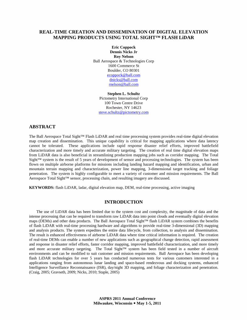
Flash LiDAR operates similarly to a camera and flashbulb (flood illumination), with the flash being provided by laser illumination and a detector that measures both intensity of the reflected target illumination and the time of flight of the reflected laser pulse. The specialized detector produces an intensity and range measurement for each pixel of the detector array. The entire scene within the sensor field of view (FOV) is imaged with a single flash of the laser, creating a 3D image cube. The resulting point cloud data is then connected to create a digital wire mesh. The wire mesh is then converted into a surface. The context image (in this case a visible image) is then draped over the surface. This entire processing chain is done in real-time. An example of a 3D image from the Ball Flash LiDAR and the sequence of image processing steps are shown in Figure 1.
The resulting 3-dimensional imagery has each pixel of the array correlated in time, which makes the processing insensitive to relative motion between the sensor and target and eliminates the need for complex processing algorithms that account for relative motion or laser scan time of the FOV. This is in contrast to a scanning LiDAR where a laser beam is raster scanned over the sensor field of view and each pixel intensity and range must be separately correlated with platform motion. The flash LiDAR system has an advantage in that the platform relative motion can be applied to the entire array of pixels, greatly reducing processing requirements and enabling real-time processing and the closed loop systems that depend on these calculations.
Figure 1. Ball’s real-time LIDAR image processing combines a visible image (A) with a 3D point cloud (B) and a wire frame surface (C) to create a fused visible / 3D draped image (D).
Flash LiDAR systems have a number of other advantages over scanning systems. Scanning systems require a
mechanism to steer the laser beam across the field of regard as well as precise pointing information for the laser. This laser pointing mechanism increases complexity, mass, power and volume requirements of the scanning LiDAR system. The flash LiDAR floods the entire scene with laser light and does not require this laser scanning system. Flash LiDAR is generally more rugged, more reliable, and requires less maintenance than a comparable scanning LiDAR system. Another notable advantage of flash systems over scanning is the reduced data volumes and processing overhead. In flash systems, a single set of state variables (position and attitude) is required for a full frame of pixels (128 x 128, or 16384 pixels). Because scanning systems build up an image over thousands of laser pulses, a set of state variables is required for each pulse. This increase in data volume from scanning systems increases the processing requirements with no improvement in the data fidelity. The Ball Aerospace Total Sight™ system exploits the reduced data volume of flash LiDAR to provide real-time processing and mapping products for civil and military time critical applications, such as disaster relief, battlefield characterization, and targeting.
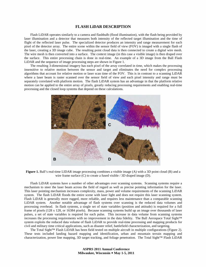
The Total Sight™ Flash LiDAR has been field tested on multiple aircraft in multiple configurations (Figure 2). These tests included landing hazard mapping and identification, urban and mountain terrain mapping and characterization, power line mapping, 3D target tracking, and foliage penetration. The Total Sight™ Flash LiDAR
A
D
C
B
ASPRS 2011 Annual Conference Milwaukee, Wisconsin ���� May 1-5, 2011
has been integrated with context cameras including visible, SWIR and MWIR allowing for multispectral scene interrogation. The most recent airborne testing was with Pictometry International Corp. (Rochester, NY) and their oblique imaging system on board a Piper Aztec, as shown in the lower three images of Figure 2.
Figure 2. The Ball Aerospace Total SightTM Flash LiDAR system has been flown on multiple platforms and in multiple configurations to meet customer and mission requirements.
REAL-TIME 3D LIDAR IMAGERY
The use of LiDAR data has been limited due to the cost and complexity of LiDAR systems, the magnitude of data and the intense processing that can be required to transform raw LiDAR data into point clouds and eventually DEMs and other data products. As mentioned previously, flash LiDAR systems reduce complexity and reduce the overall data and processing requirements, while preserving the fidelity of the 3D image data. Ball Aerospace Internal Research and Development (IRAD) efforts have been focused on converting these advantages into useable data products through proprietary algorithms and processing hardware configurations. These data products are unique in that they are created in real-time (milliseconds to a few seconds). The real-time processing is enabled by a combination of FPGA, embedded and non-embedded processing hardware and algorithms optimized for that hardware.
The overarching challenge is to get useful information to the user to support real-time or near-real-time decisions. In some scenarios, this means embedded data processing to the point of a processed DEM, performed at the sensor and at the frame rate of the sensor. In other scenarios, this might mean basic pixel processing and color fusion at the sensor to decrease the data bandwidth, followed by a radio frequency (RF) downlink, with further non-embedded processing on the ground. In either case, the latency to produce a georegistered DEM or other actionable intelligence products is on the order of a few seconds. Data can be output to storage or other processing ‘consumers’ at any intermediate point in the processing chain. Ball is well versed in implementing and optimizing the real-time processing chain to meet the requirements of any given operational scenario.
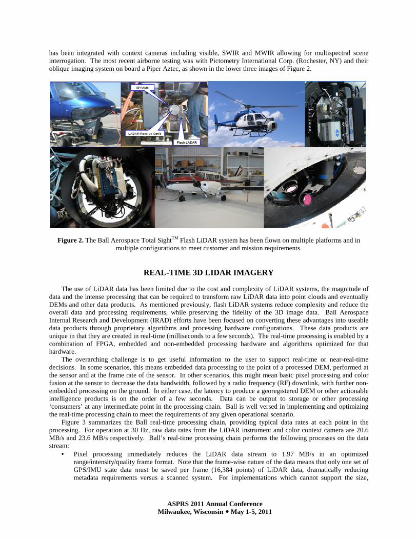
Figure 3 summarizes the Ball real-time processing chain, providing typical data rates at each point in the processing. For operation at 30 Hz, raw data rates from the LiDAR instrument and color context camera are 20.6 MB/s and 23.6 MB/s respectively. Ball’s real-time processing chain performs the following processes on the data stream:
• Pixel processing immediately reduces the LiDAR data stream to 1.97 MB/s in an optimized range/intensity/quality frame format. Note that the frame-wise nature of the data means that only one set of GPS/IMU state data must be saved per frame (16,384 points) of LiDAR data, dramatically reducing metadata requirements versus a scanned system. For implementations which cannot support the size,
ASPRS 2011 Annual Conference Milwaukee, Wisconsin ���� May 1-5, 2011
weight, and power for further onboard processing, this (or after optional Color Fusion) is the optimum point for an RF downlink in this case.
• Orthorectification expands the data stream from a frame-wise format to a point cloud form. In this form it is possible to drape high-resolution color imagery over the 3D surface sampled by the LiDAR, and present full motion 3D video in real-time to a user on an off-the-shelf PC running the Ball LiDAR Viewer.
• Geolocation maintains the point-cloud format of the data but georeferences the points, so that they are suitable for output to LAS format or for accumulation into an extended-area map. Up to this point in the processing , the latency introduced to the data stream is << 1 sec.
• Scene stitching is an enhancement to Geolocation that is uniquely available to Flash LiDAR data due to its frame-wise nature. Intra-scene features can be utilized to improve the alignment of points from one frame to its neighbors.
• Regridding involves downsampling the LiDAR data to a predefined grid resolution specified by the mission requirements. This can result in dramatic reductions in data volume. For example, in one set of Ball test flights, a multiple-pass data collection coupled with the collection geometry and airspeed resulted in significant oversampling of the area of interest. Not only did this enable improved alignment of the data frames with each other, but when the data was resampled to a 30 cm fixed grid, the total data volume was reduced by over 90% while at the same time realizing a significant improvement (reduction) in range noise.
Figure 3. The Ball Aerospace Total Sight™ real-time processing chain enables map as you fly capability and reduces data downlink bandwidth requirements for real-time delivery. The processing chain and outputs are
configurable based on mission and data requirements; data rates shown are for operation at 30 Hz, uncompressed.
ASPRS 2011 Annual Conference Milwaukee, Wisconsin ���� May 1-5, 2011
APPLICATION OF REAL-TIME DEMS FROM FLASH LIDAR
The integration of flash LiDAR systems with real-time processing hardware and algorithms enables a number of new missions and markets for our customers. Some examples of the utility of real-time processing and dissemination are discussed below. Map As You Fly
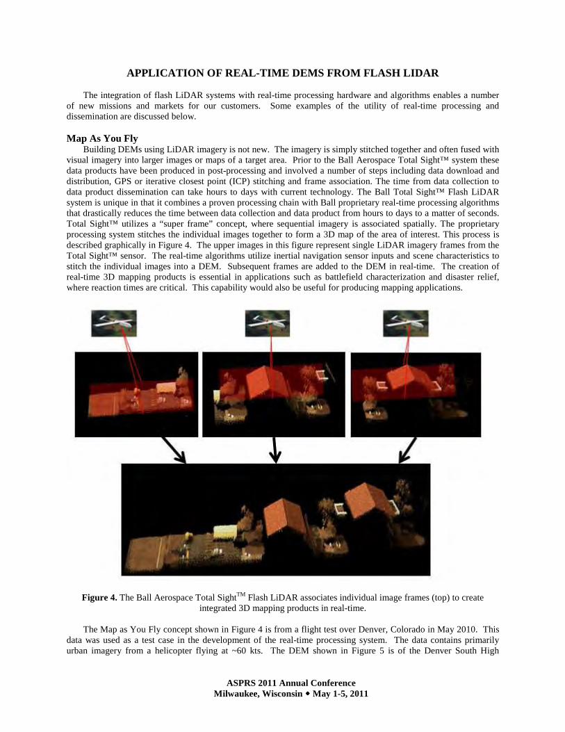
Building DEMs using LiDAR imagery is not new. The imagery is simply stitched together and often fused with visual imagery into larger images or maps of a target area. Prior to the Ball Aerospace Total Sight™ system these data products have been produced in post-processing and involved a number of steps including data download and distribution, GPS or iterative closest point (ICP) stitching and frame association. The time from data collection to data product dissemination can take hours to days with current technology. The Ball Total Sight™ Flash LiDAR system is unique in that it combines a proven processing chain with Ball proprietary real-time processing algorithms that drastically reduces the time between data collection and data product from hours to days to a matter of seconds. Total Sight™ utilizes a “super frame” concept, where sequential imagery is associated spatially. The proprietary processing system stitches the individual images together to form a 3D map of the area of interest. This process is described graphically in Figure 4. The upper images in this figure represent single LiDAR imagery frames from the Total Sight™ sensor. The real-time algorithms utilize inertial navigation sensor inputs and scene characteristics to stitch the individual images into a DEM. Subsequent frames are added to the DEM in real-time. The creation of real-time 3D mapping products is essential in applications such as battlefield characterization and disaster relief, where reaction times are critical. This capability would also be useful for producing mapping applications.
Figure 4. The Ball Aerospace Total SightTM Flash LiDAR associates individual image frames (top) to create integrated 3D mapping products in real-time.
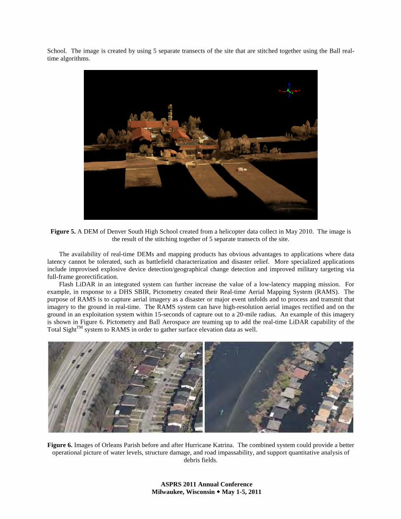
The Map as You Fly concept shown in Figure 4 is from a flight test over Denver, Colorado in May 2010. This
data was used as a test case in the development of the real-time processing system. The data contains primarily urban imagery from a helicopter flying at ~60 kts. The DEM shown in Figure 5 is of the Denver South High
ASPRS 2011 Annual Conference Milwaukee, Wisconsin ���� May 1-5, 2011
School. The image is created by using 5 separate transects of the site that are stitched together using the Ball real-time algorithms.
Figure 5. A DEM of Denver South High School created from a helicopter data collect in May 2010. The image is the result of the stitching together of 5 separate transects of the site.
The availability of real-time DEMs and mapping products has obvious advantages to applications where data
latency cannot be tolerated, such as battlefield characterization and disaster relief. More specialized applications include improvised explosive device detection/geographical change detection and improved military targeting via full-frame georectification.
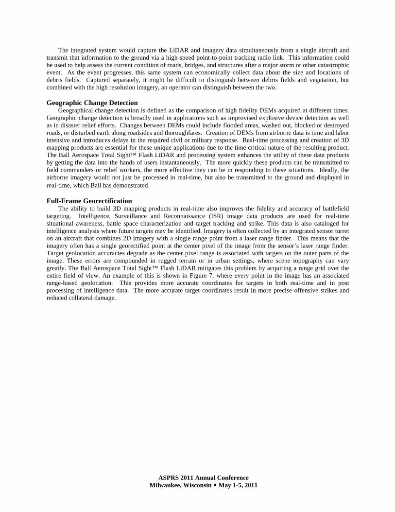
Flash LiDAR in an integrated system can further increase the value of a low-latency mapping mission. For example, in response to a DHS SBIR, Pictometry created their Real-time Aerial Mapping System (RAMS). The purpose of RAMS is to capture aerial imagery as a disaster or major event unfolds and to process and transmit that imagery to the ground in real-time. The RAMS system can have high-resolution aerial images rectified and on the ground in an exploitation system within 15-seconds of capture out to a 20-mile radius. An example of this imagery is shown in Figure 6. Pictometry and Ball Aerospace are teaming up to add the real-time LiDAR capability of the Total SightTM system to RAMS in order to gather surface elevation data as well.
Figure 6. Images of Orleans Parish before and after Hurricane Katrina. The combined system could provide a better
operational picture of water levels, structure damage, and road impassability, and support quantitative analysis of debris fields.
ASPRS 2011 Annual Conference Milwaukee, Wisconsin ���� May 1-5, 2011
The integrated system would capture the LiDAR and imagery data simultaneously from a single aircraft and transmit that information to the ground via a high-speed point-to-point tracking radio link. This information could be used to help assess the current condition of roads, bridges, and structures after a major storm or other catastrophic event. As the event progresses, this same system can economically collect data about the size and locations of debris fields. Captured separately, it might be difficult to distinguish between debris fields and vegetation, but combined with the high resolution imagery, an operator can distinguish between the two. Geographic Change Detection
Geographical change detection is defined as the comparison of high fidelity DEMs acquired at different times. Geographic change detection is broadly used in applications such as improvised explosive device detection as well as in disaster relief efforts. Changes between DEMs could include flooded areas, washed out, blocked or destroyed roads, or disturbed earth along roadsides and thoroughfares. Creation of DEMs from airborne data is time and labor intensive and introduces delays in the required civil or military response. Real-time processing and creation of 3D mapping products are essential for these unique applications due to the time critical nature of the resulting product. The Ball Aerospace Total Sight™ Flash LiDAR and processing system enhances the utility of these data products by getting the data into the hands of users instantaneously. The more quickly these products can be transmitted to field commanders or relief workers, the more effective they can be in responding to these situations. Ideally, the airborne imagery would not just be processed in real-time, but also be transmitted to the ground and displayed in real-time, which Ball has demonstrated. Full-Frame Georectification
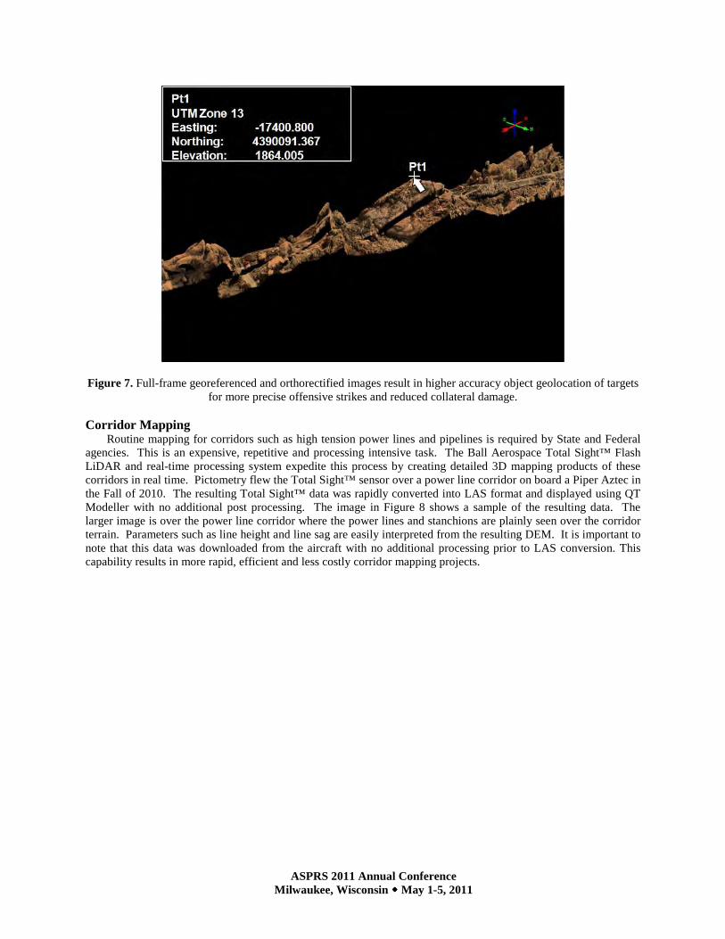
The ability to build 3D mapping products in real-time also improves the fidelity and accuracy of battlefield targeting. Intelligence, Surveillance and Reconnaissance (ISR) image data products are used for real-time situational awareness, battle space characterization and target tracking and strike. This data is also cataloged for intelligence analysis where future targets may be identified. Imagery is often collected by an integrated sensor turret on an aircraft that combines 2D imagery with a single range point from a laser range finder. This means that the imagery often has a single georectified point at the center pixel of the image from the sensor’s laser range finder. Target geolocation accuracies degrade as the center pixel range is associated with targets on the outer parts of the image. These errors are compounded in rugged terrain or in urban settings, where scene topography can vary greatly. The Ball Aerospace Total Sight™ Flash LiDAR mitigates this problem by acquiring a range grid over the entire field of view. An example of this is shown in Figure 7, where every point in the image has an associated range-based geolocation. This provides more accurate coordinates for targets in both real-time and in post processing of intelligence data. The more accurate target coordinates result in more precise offensive strikes and reduced collateral damage.
ASPRS 2011 Annual Conference Milwaukee, Wisconsin ���� May 1-5, 2011
Figure 7. Full-frame georeferenced and orthorectified images result in higher accuracy object geolocation of targets for more precise offensive strikes and reduced collateral damage.
Corridor Mapping
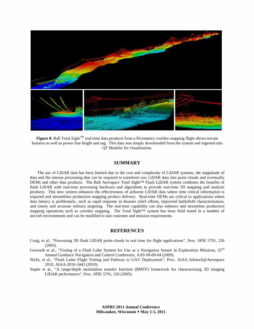
Routine mapping for corridors such as high tension power lines and pipelines is required by State and Federal agencies. This is an expensive, repetitive and processing intensive task. The Ball Aerospace Total Sight™ Flash LiDAR and real-time processing system expedite this process by creating detailed 3D mapping products of these corridors in real time. Pictometry flew the Total Sight™ sensor over a power line corridor on board a Piper Aztec in the Fall of 2010. The resulting Total Sight™ data was rapidly converted into LAS format and displayed using QT Modeller with no additional post processing. The image in Figure 8 shows a sample of the resulting data. The larger image is over the power line corridor where the power lines and stanchions are plainly seen over the corridor terrain. Parameters such as line height and line sag are easily interpreted from the resulting DEM. It is important to note that this data was downloaded from the aircraft with no additional processing prior to LAS conversion. This capability results in more rapid, efficient and less costly corridor mapping projects.
ASPRS 2011 Annual Conference Milwaukee, Wisconsin ���� May 1-5, 2011
Figure 8. Ball Total SightTM real-time data products from a Pictometry corridor mapping flight shows terrain features as well as power line height and sag. This data was simply downloaded from the system and ingested into
QT Modeler for visualization.
SUMMARY
The use of LiDAR data has been limited due to the cost and complexity of LiDAR systems, the magnitude of data and the intense processing that can be required to transform raw LiDAR data into point clouds and eventually DEMs and other data products. The Ball Aerospace Total Sight™ Flash LiDAR system combines the benefits of flash LiDAR with real-time processing hardware and algorithms to provide real-time 3D mapping and analysis products. This new system enhances the effectiveness of airborne LiDAR data where time critical information is required and streamlines production mapping product delivery. Real-time DEMs are critical to applications where data latency is problematic, such as rapid response in disaster relief efforts, improved battlefield characterization, and timely and accurate military targeting. The real-time capability can also enhance and streamline production mapping operations such as corridor mapping. The Total Sight™ system has been field tested in a number of aircraft environments and can be modified to suit customer and mission requirements.
REFERENCES Craig, et al., “Processing 3D flash LIDAR point-clouds in real time for flight applications”, Proc. SPIE 5791, 226
(2005). Gravseth et al., “Testing of a Flash Lidar System for Use as a Navigation Sensor in Exploration Missions, 32nd
Annual Guidance Navigation and Control Conference, AAS 09-09-04 (2009). Nicks, et al., “Flash Ladar Flight Testing and Pathway to UAV Deployment”, Proc. AIAA Infotech@Aerospace
2010, AIAA-2010-3443 (2010). Staple et al., “A range/depth modulation transfer function (RMTF) framework for characterizing 3D imaging
LIDAR performance”, Proc. SPIE 5791, 226 (2005).