Embed Size (px)
Citation preview
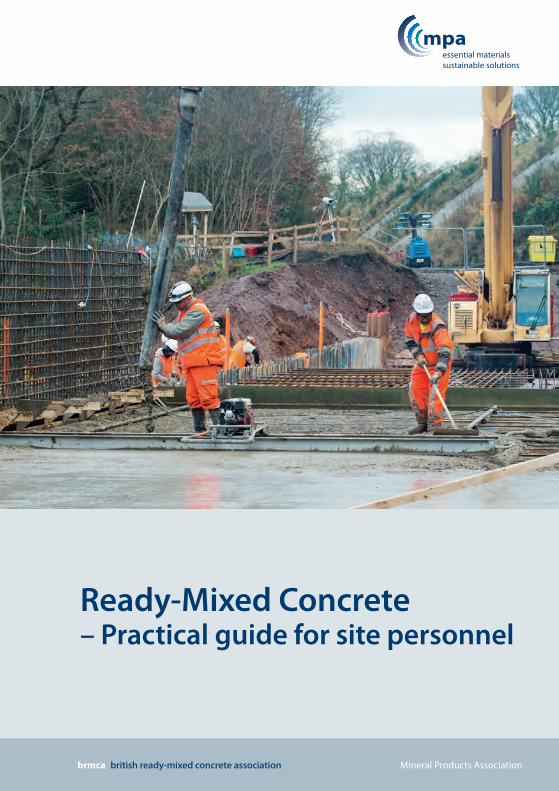
Ready-Mixed Concrete– Practical guide for site personnel
brmca british ready-mixed concrete association Mineral Products Association

2
Health and SafetyHealth and safetyAll construction sites include potential hazards where appropriate precautions are required, and where the legal responsibility for health and safety is likely to be the project manager or those responsible for the construction work. However, everyone working on a construction site, including those delivering goods and services, is responsible for their safety and the safety of those around them. The Health and Safety Executive provides a wide range of useful guidance, downloadable at no cost from www.hse.gov.uk, and include:
¡ Managing health and safety in construction. Construction (Design and Management) Regulations 2015. Guidance on regulations. Health and Safety Executive, L153, April 2015.
¡ Health and safety in construction. Health and Safety Executive, HSG150, Third edition. 2006.
¡ Personal protective equipment (PPE) at work. Health and Safety Executive, INDG174(rev2), August 2013.
¡ HSE information sheet – Cement. CIS26(rev2). 2002.
¡ HSE information sheet – Construction dust. CIS36(rev2). 2013
Cement burnsThere are particular concerns where skin comes
into contact with fresh concrete, skin irritations are likely to occur owing to the alkaline nature of cement. The abrasive effects of sand and aggregate in the concrete can aggravate the condition. Potential effects range from dry skin, irritant contact dermatitis, to – in cases of prolonged exposure – severe burns.
Take precautions to avoid dry cement entering the eyes, mouth and nose when mixing mortar or concrete by wearing suitable protective clothing. Take care to prevent fresh concrete from entering boots and use working methods that do not require personnel to kneel in fresh concrete.Unlike heat burns, cement burns might not be felt for some time after contact with fresh concrete, so there might be no warning of damage occurring.
If cement or concrete enters the eye, immediately wash it out thoroughly with clean water and seek medical treatment without delay. Wash wet concrete off the skin immediately. Barrier creams may be used to supplement protective clothing but are not an alternative means of protection.
This booklet is available for download from www.brmca.org
Sampling and testing procedures are included as appendices in this document.
A - Sampling concrete B - Consistence tests C - Air content tests D - Strength test specimens
For hard copies please refer to the contact page of the BRMCA website: www.brmca.org.uk
Personal Protective Equipment (PPE) for working with concrete.
3
Health and safety
1 Introduction .............................................................. 4
2 Specifying concrete ................................................ 5
2.1 General
2.2 Consistence
2.3 Designated concretes
2.4 Ordering
3 Delivery ....................................................................... 8
3.1 Site preparation
3.2 Receiving
3.3 Sampling and testing
4 Placing concrete ....................................................10
4.1 General
4.2 Time limits
4.3 Hot weather
4.4 Cold weather
4.5 Formwork
4.6 Placing concrete
4.7 Deep beams and columns
4.8 Slab formwork
4.9 Cold joints in mass concrete
5. Compacting concrete ...........................................13
5.1 Entrapped air
5.2 Poker vibrators
5.3 External vibrators
5.4 Vibrating beams
5.5 Plastic settlement and voids
6. Finishing concrete ..................................................16
6.1 General
6.2 Formed surface finishes
6.3 Unformed surface finishes
7. Curing concrete ......................................................18
7.1 General
7.2 Polythene sheeting
7.3 Sprayed membrane
Appendices
A Sampling concrete ..............................................22
A.1 General
A.2 Composite sample
A.3 Spot sample from initial discharge
B Consistence tests ..................................................24
B.1 Slump test
B.2 Flow test
B.3 Slump-flow test
B.4 Consistence retention testing
C Air content tests ....................................................31
C.1 General
C.2 Water column method
C.3 Pressure gauge method
D Strength test specimens ....................................34
D.1 General
D.2 Cubes – normal consistence concrete
D.3 Cube specimens, cement bound concrete
or granular mixes
D.4 Stripping and storing
Standards ......................................................................39
Contents
4
Practical guide for site personnel
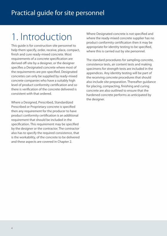
1. IntroductionThis guide is for construction site personnel to help them specify, order, receive, place, compact, finish and cure ready-mixed concrete. Most requirements of a concrete specification are derived off-site by a designer, or the designer specifies a Designated concrete where most of the requirements are pre-specified. Designated concretes can only be supplied by ready-mixed concrete companies who have a suitably high level of product conformity certification and sothere is verification of the concrete delivered is consistent with that ordered.
Where a Designed, Prescribed, Standardized Prescribed or Proprietary concrete is specified then any requirement for the producer to have product conformity certification is an additional requirement that should be included in the specification. This requirement may be specified by the designer or the contractor. The contractor also has to specify the required consistence, that is the workability, of the concrete to be delivered and these aspects are covered in Chapter 2.
Where Designated concrete is not specified and where the ready-mixed concrete supplier has no product conformity certification then it may be appropriate for identity testing to be specified, where this is carried out by site personnel. The standard procedures for sampling concrete, consistence tests, air content tests and making specimens for strength tests are included in the appendices. Any identity testing will be part of the receiving concrete procedures that should also include site preparation. Thereafter guidance for placing, compacting, finishing and curing concrete are also outlined to ensure that the hardened concrete performs as anticipated by the designer.
5
Specifying concrete
2. Specifying concrete2.1 GeneralThe concrete specification given to the ready-mixed concrete producer should include all the required properties. Although the designer specifies those properties of concrete required to ensure it remains serviceable during its working life it is up to the contractor to complete the specification. Where the designer has not included a requirement for the ready-mixed concrete producer to have product conformity certification then the contractor should take this option to ensure the concrete delivered is of the required performance.
Product conformity certification.QSRMC and BSI Kitemark Scheme for ready-mixed concrete set the required product conformity certification level standards for producers to supply Designated concretes. Companies awarded QSRMC or BSI Kitemark certification are licensed to use the Certification Mark on literature and documentation, including quotations and delivery dockets.
The contractor also adds the additional properties required for transportation after delivery, placing, compaction and any requirement for early age strength. In most cases the contractor only needs to specify the required consistence where this is added to the designer’s specified requirements to complete the specification that goes to the ready-mixed concrete producer.
2.2 ConsistenceConsistence is the European and British Standard word for workability. For the most common applications consistence is specified by slump class, where consistence is measured using the slump test as described in Appendix B.1. For more workable concrete consistence should be specified by slump-flow class, where the test is described in Appendix B.3.
Specifying and ordering the highest consistence class concrete possible will minimise the time required to place and compact concrete. In general this will minimise the cost of construction as the cost of extra manpower to place low workability concrete generally exceeds the extra cost of higher workability concrete.
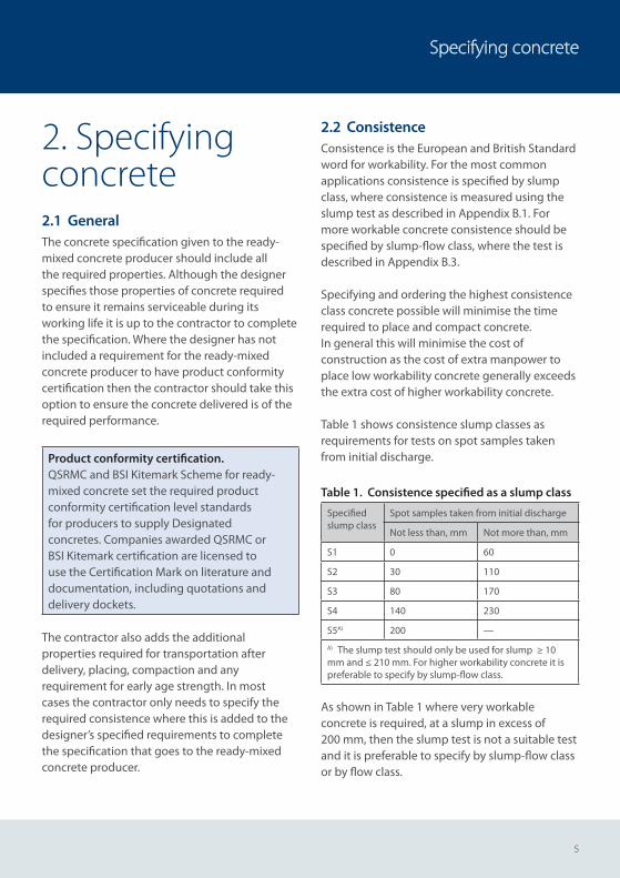
Table 1 shows consistence slump classes as requirements for tests on spot samples taken from initial discharge.
Table 1. Consistence specified as a slump class
Specified slump class
Spot samples taken from initial discharge
Not less than, mm Not more than, mm
S1 0 60
S2 30 110
S3 80 170
S4 140 230
S5A) 200 —
A) The slump test should only be used for slump ≥ 10 mm and ≤ 210 mm. For higher workability concrete it is preferable to specify by slump-flow class.
As shown in Table 1 where very workable concrete is required, at a slump in excess of 200 mm, then the slump test is not a suitable test and it is preferable to specify by slump-flow class or by flow class.
6
Practical guide for site personnel
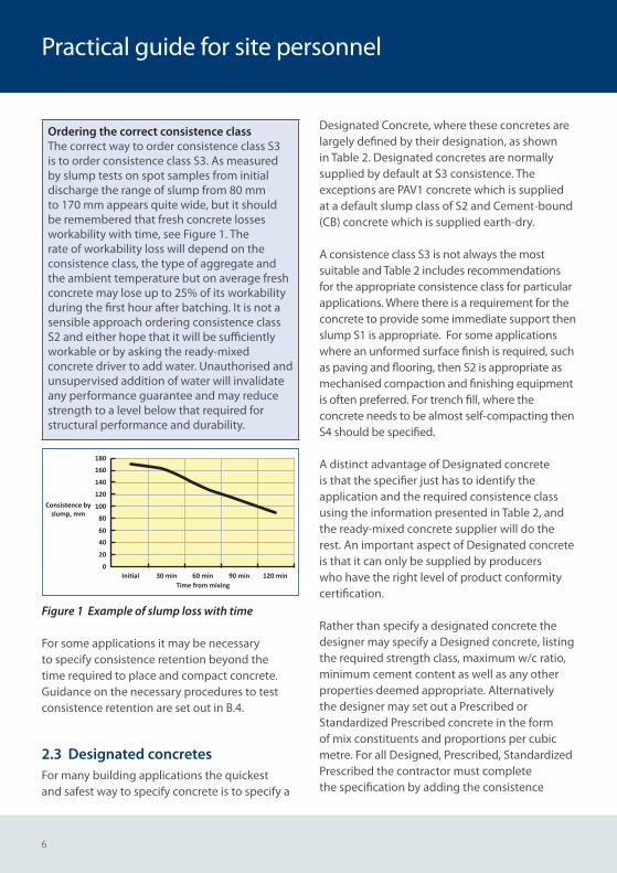
Ordering the correct consistence classThe correct way to order consistence class S3 is to order consistence class S3. As measured by slump tests on spot samples from initial discharge the range of slump from 80 mm to 170 mm appears quite wide, but it should be remembered that fresh concrete losses workability with time, see Figure 1. The rate of workability loss will depend on the consistence class, the type of aggregate and the ambient temperature but on average fresh concrete may lose up to 25% of its workability during the first hour after batching. It is not a sensible approach ordering consistence class S2 and either hope that it will be sufficiently workable or by asking the ready-mixed concrete driver to add water. Unauthorised and unsupervised addition of water will invalidate any performance guarantee and may reduce strength to a level below that required for structural performance and durability.
180
Initial 30 min 60 minTime from mixing
Consistence byslump, mm
90 min 120 min
160
140
120
100
80
60
40
20
0
Figure 1 Example of slump loss with time
For some applications it may be necessary to specify consistence retention beyond the time required to place and compact concrete. Guidance on the necessary procedures to test consistence retention are set out in B.4.
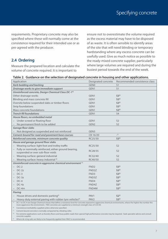
2.3 Designated concretesFor many building applications the quickest and safest way to specify concrete is to specify a
Designated Concrete, where these concretes are largely defined by their designation, as shown in Table 2. Designated concretes are normally supplied by default at S3 consistence. The exceptions are PAV1 concrete which is supplied at a default slump class of S2 and Cement-bound (CB) concrete which is supplied earth-dry.
A consistence class S3 is not always the most suitable and Table 2 includes recommendations for the appropriate consistence class for particular applications. Where there is a requirement for the concrete to provide some immediate support then slump S1 is appropriate. For some applications where an unformed surface finish is required, such as paving and flooring, then S2 is appropriate as mechanised compaction and finishing equipment is often preferred. For trench fill, where the concrete needs to be almost self-compacting then S4 should be specified.
A distinct advantage of Designated concrete is that the specifier just has to identify the application and the required consistence class using the information presented in Table 2, and the ready-mixed concrete supplier will do the rest. An important aspect of Designated concrete is that it can only be supplied by producers who have the right level of product conformity certification.
Rather than specify a designated concrete the designer may specify a Designed concrete, listing the required strength class, maximum w/c ratio, minimum cement content as well as any other properties deemed appropriate. Alternatively the designer may set out a Prescribed or Standardized Prescribed concrete in the form of mix constituents and proportions per cubic metre. For all Designed, Prescribed, Standardized Prescribed the contractor must complete the specification by adding the consistence
7
Specifying concrete
requirements. Proprietary concrete may also be specified where these will normally come at the consistence required for their intended use or as pre-agreed with the producer.
2.4 OrderingMeasure the prepared location and calculate the volume of concrete required. It is important to
ensure not to overestimate the volume required as the excess material may have to be disposed of as waste. It is often sensible to identify areas of the site that will need blinding or temporary hardstanding where any excess concrete can be usefully used. Give as much notice as possible to the ready-mixed concrete supplier, particularly where large volumes are required and during the busiest period towards the end of the week.
Table 2. Guidance on the selection of designated concrete in housing and other applications.Application Designated concrete Recommended consistence classKerb bedding and backing GEN0 S1Drainage works to give immediate support GEN1 S1Unreinforced concrete, Design Chemical Class DC-1A)
Other drainage works GEN1 S3B)
Blinding and mass concrete fill GEN1 S3B)
Oversite below suspended slabs or timber floors GEN1 S3B)
Strip foundations GEN1 S3B)
Mass concrete foundations GEN1 S3B)
Trench fill foundations GEN1 S4House floors, no embedded metal – Under screed or floating floor GEN1 S2– No permanent finish to be added GEN2 S2Garage floor slabs– Not designed as suspended and not reinforced GEN3Cement-bound for road and pavement base courses CB 16/20 -C)
Reinforced concrete, minimum concrete quality RC25/30 S3B)
House and garage ground floor slabs– Wearing surface: light foot and trolley traffic RC25/30 S2– Fully or nominally reinforced, either ground bearing, suspended or over sub-floor voids
RC28/35 S2
– Wearing surface: general industrial RC32/40 S2– Wearing surface: heavy industrial D) RC40/50 S2Unreinforced concrete in aggressive chemical environment A)
– DC-2 FND2 S3B)
– DC-2z FND2Z S3B)
– DC-3 FND3 S3B)
– DC-3z FND3Z S3B)
– DC-4 FND4 S3B)
– DC-4z FND4Z S3B)
– DC-4m FND4M S3B)
Paving – House drives and domestic parkingE) PAV1 S2B)
– Heavy-duty external paving with rubber tyre vehiclesD) PAV2 S3B)
A) DC-1 to DC-4 are Design Chemical classes that define a resistance level for concrete exposed to aggressive chemical environments, where the higher the number the more aggressive the environment. FND concretes are supplied at a minimum strength class of C25/30.
B) Consistence/workability supplied unless otherwise specified.C) Cement-bound concrete is normally compacted by vibrating roller. D) For extreme applications such as foundry floors and busy public roads then special high performance concrete may be required. Seek specialist advice and consult
concrete supplier.E) Where de-icing salts are likely to be frequently applied then PAV2 is recommended.
8
Practical guide for site personnel
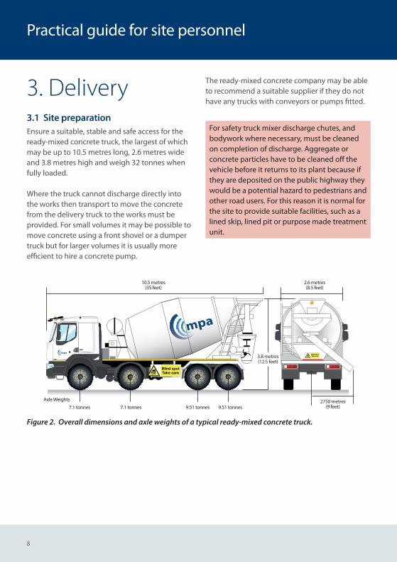
3. Delivery3.1 Site preparation Ensure a suitable, stable and safe access for the ready-mixed concrete truck, the largest of which may be up to 10.5 metres long, 2.6 metres wide and 3.8 metres high and weigh 32 tonnes when fully loaded.
Where the truck cannot discharge directly into the works then transport to move the concrete from the delivery truck to the works must be provided. For small volumes it may be possible to move concrete using a front shovel or a dumper truck but for larger volumes it is usually more efficient to hire a concrete pump.
The ready-mixed concrete company may be able to recommend a suitable supplier if they do not have any trucks with conveyors or pumps fitted.
For safety truck mixer discharge chutes, and bodywork where necessary, must be cleaned on completion of discharge. Aggregate or concrete particles have to be cleaned off the vehicle before it returns to its plant because if they are deposited on the public highway they would be a potential hazard to pedestrians and other road users. For this reason it is normal for the site to provide suitable facilities, such as a lined skip, lined pit or purpose made treatment unit.
EXAMPLE WARNING TEXT
Axle Weights
7.1 tonnes 7.1 tonnes 9.51 tonnes 9.51 tonnes
10.5 metres(35 feet)
2750 metres(9 feet)
2.6 metres(8.5 feet)
3.8 metres(12.5 feet)
Figure 2. Overall dimensions and axle weights of a typical ready-mixed concrete truck.
9
Delivery
3.2 Receiving
For health and safety it is necessary for the contractor to carry out a risk assessment to cover the delivery, receipt, discharge and release of ready-mixed concrete delivery vehicles. Most importantly there is a requirement to provide a banksman to supervise the safe movement and positioning of the ready-mixed concrete truck.
The delivery docket should be checked to ensure it is the correct ready-mixed concrete truck delivering the specified concrete – particularly where a number of deliveries for different parts of the site are expected. The driver should be directed to where the concrete is to be discharged and told where the chute cleaning facilities are located.
3.3 Sampling and testingWhere the ready-mixed concrete supplier has the right level of product conformity certification then sampling and testing concrete at delivery should not be necessary.
Where the ready-mixed concrete supplier has no product conformity certification or just a low level quality management system, or where site sampling and testing is specified, then it is appropriate to carry out sampling and testing on site. This type of testing is called ‘identity testing’, and is carried out to determine whether selected batches or loads of concrete come from a conforming population of production concrete. These tests are often specified as a spot check on the ready-mixed concrete supplier or where more extensive testing regimes are called up as part of site quality assurance procedures.
Site testing, Inform the ready-mixed concrete supplierIt is important to inform the ready-mixed concrete supplier if site testing is carried out to ensure that it is to an agreed sampling and testing plan in accordance with the Standard requirements.
Sampling and testing of fresh concrete must be carried out in accordance with standard procedures, where these procedures are summarised as appendices;
Appendix A: Sampling
Appendix B: Consistence testing
Appendix C: Air content testing
Appendix D: Specimens for strength tests
10
Practical guide for site personnel
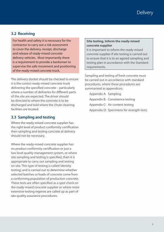
4. Concrete placing4.1 GeneralGood concrete is concrete that has been placed, compacted, fi nished and cured properly. Most problems associated with in-situ concrete are attributable to combinations of poor compaction, fi nishing and curing. Compaction is most effi ciently achieved if the concrete is placed and vibrated as soon as possible after delivery. Curing is particularly important in hot dry weather or in cold weather.
Figure 3. Concrete placing directly from the ready-mixed concrete chute.
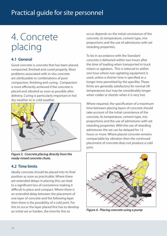
4.2 Time limitsIdeally concrete should be placed into its fi nal position as soon as practicable. Where there are extended delays in placing this can lead to a signifi cant loss of consistence making it diffi cult to place and compact. Where there is an extended delay between the placement of one layer of concrete and the following layer then there is the possibility of a cold joint. For this to occur the layer placed fi rst has to develop an initial set or harden, the time for this to
occur depends on the initial consistence of the concrete, its temperature, cement type, mix proportions and the use of admixtures with set retarding properties.
To be in accordance with the Standard concrete is delivered within two hours after the time of loading when transported in truck mixers or agitators. This is reduced to within one hour where non-agitating equipment is used, unless a shorter time is specifi ed or a longer time permitted by the specifi er. These limits are generally satisfactory for normal UK temperatures but may be considerably longer when colder or shorter when it is very hot.
Where required, the specifi cation of a maximum time between placing layers of concrete should take account of the initial consistence of the concrete, its temperature, cement type, mix proportions and the use of admixtures with set retarding properties. With the use of retarding admixtures the set can be delayed for 12 hours or more. Where placed concrete remains compactable by vibration then the continued placement of concrete does not produce a cold joint.
Figure 4. Placing concrete using a pump
11
Concrete placing
4.3 Concrete in hot weatherHigh temperatures increase the rate at which the concrete loses consistence. Where the loss of consistence is going to make placing and compacting concrete diffi cult it may be necessary to retard concrete setting. This is most readily achieved by the use of suitable chemical admixtures during batching at the concrete plant. Where the specifi cation permits it may also be possible to use a slower setting cement or increase the proportion of addition in the cement.
Unless otherwise specifi ed the temperature of the fresh concrete at delivery should not exceed 35⁰C. It is known that the stability of the entrained air content is reduced at placing temperatures above about 30°C and so a maximum concrete temperature of 30°C is appropriate for air-entrained concrete. Where it is necessary to specify a lower temperature than these levels the possibility should be discussed and agreed with the ready-mixed concrete supplier.
4.4 Concrete in cold weatherIn cold weather it is important to ensure that fresh concrete does not freeze before it has hardened, and this can normally be achieved by providing insulation to cover unformed surfaces or to provide insulated formwork. To be in accordance with British and European Standards the temperature of the fresh concrete should not be less than 5 ⁰C at the time of delivery, and providing the concrete is protected from sharply falling ambient temperatures then the risk of freezing is minimal. During cold weather concrete will take longer to stiff en, harden and gain strength which may delay following construction operations such as fi nishing fl oors or striking formwork.
Where there is a need to specify a minimum delivery temperature higher than 5 ⁰C then this should be discussed and agreed with the ready-mixed concrete supplier.
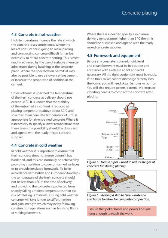
4.5 Formwork and equipmentBefore any concrete is placed, rigid, level and clean formwork must be in position and accessible with a release agent applied if necessary. All the right equipment must be ready. If the truck mixer cannot discharge directly into the forms, you will need skips, barrows or pumps. You will also require pokers, external vibrators or vibrating beams to compact the concrete after placing.
Kicker
Heightof Fall
Reinforcement Cage
Formwork
Tremie
Figure 5. Tremie pipes – used to reduce height of concrete fall during placing.
Figure 6. Striking a slab to level – note the surcharge to allow for complete compaction.
Ensure that poker hoses and power lines are long enough to reach the work.
12
Practical guide for site personnel
4.6 Placing concreteThe rate of delivery should match the rate of placing and compaction which should be high enough to avoid cold joints and low enough to prevent excessive settlement or overloading of the formwork. A thorough inspection of any reinforcement should also be made prior to placing the concrete. Place the concrete in a series of layers of roughly equal depth – normally 300-500 mm – and compact each layer with a vibrator. Never let the concrete pile up in large heaps or sloping layers.
Take care to ensure that the concrete during placing does not strike the face of the formwork; otherwise it may cause segregation, aff ect the surface fi nish or cause displacement of reinforcement. Remember to note the ambient temperatures, and concrete consistence class prior to placement.
4.7 Deep walls and columnsWhen placing concrete in deep walls and columns it should not be allowed to free-fall more than about a metre unless the concrete has been specifi cally designed to do so. Rather than free-fall it is preferable to use a pump, tremie pipe or where access is particularly restricted ‘letterboxes’ through the formwork. For highly consistent fi nishes the rate of placing should not be less than two vertical metres per hour.
The poker should be lifted vertically out then re-inserted to avoid hitting tie-bolts.
Avoid the temptation with small columns to try and place the concrete faster than it can be compacted. Use a board and shovel, and lower the poker down before adding each 300 mm depth of concrete.
Generally there will not be enough room in small columns for more than one poker to be used at a time. For larger columns it may also be sensible to use a single poker, removing and re-inserting as necessary.
4.8 Slab formworkExcept where light mesh is required near the surface slab formwork should be overfi lled, or surcharged, by around 15 mm to allow for settlement in slabs. The height of surcharge used will depend on experience but will be higher the deeper the slab.
Where light mesh is required near the top of the slab tamp the concrete to mesh level with a notched beam, and then lay the reinforcement, cover with more concrete including a little surcharge and then compact and fi nish. Never tread on the mesh.
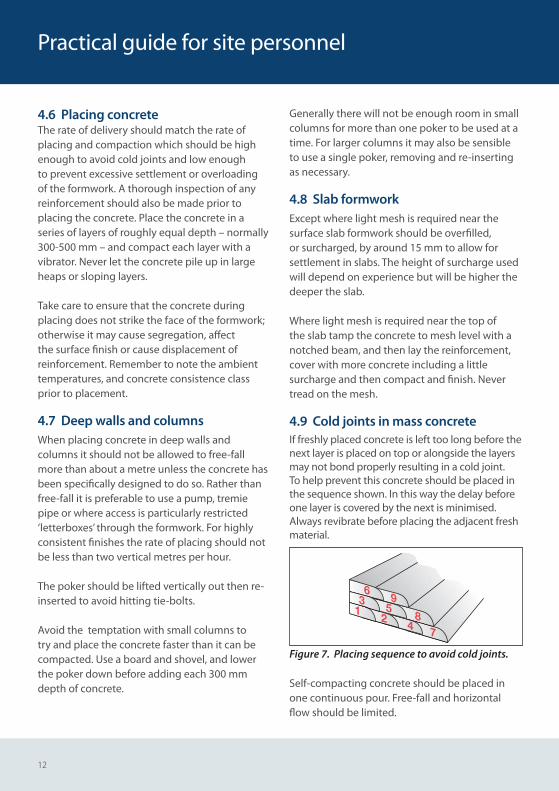
4.9 Cold joints in mass concreteIf freshly placed concrete is left too long before the next layer is placed on top or alongside the layers may not bond properly resulting in a cold joint. To help prevent this concrete should be placed in the sequence shown. In this way the delay before one layer is covered by the next is minimised. Always revibrate before placing the adjacent fresh material.
95
2 84 7
63
1
Figure 7. Placing sequence to avoid cold joints.
Self-compacting concrete should be placed in one continuous pour. Free-fall and horizontal fl ow should be limited.
13
Concrete placing
5. Compacting concrete5.1 Entrapped airAll fresh concrete contains entrapped air that needs to be removed otherwise it forms bubbles, blowholes and other voids within the concrete. These may reduce the bond between the concrete and reinforcement. Before compaction fresh concrete may have up to 20% entrapped air. Every 1% of trapped air reduces the concrete strength by about 5% and so full compaction is very important.
5.2 Poker vibratorsThere are three main types of compacting equipment – poker vibrators, external vibrators and vibrating beams.
Compaction is complete when all but the smallest bubbles stop rising to the surface. This is normally when the sound of the poker stops changing. With non-air-entrained concrete a glistening fi lm of mortar on the concrete surface is a sign of full compaction.
In general, vibrate a bit longer than you think necessary – except for slabs and high workability concrete, where excessive surface mortar may result.
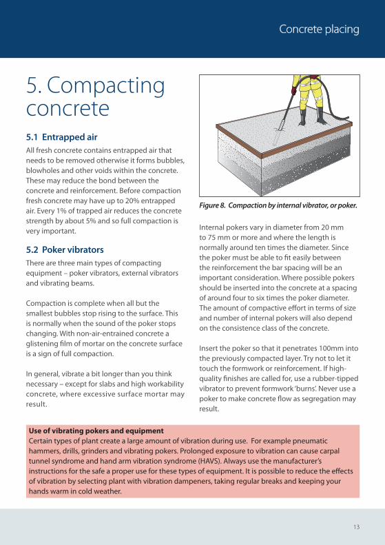
Figure 8. Compaction by internal vibrator, or poker.
Internal pokers vary in diameter from 20 mm to 75 mm or more and where the length is normally around ten times the diameter. Since the poker must be able to fi t easily between the reinforcement the bar spacing will be an important consideration. Where possible pokers should be inserted into the concrete at a spacing of around four to six times the poker diameter. The amount of compactive eff ort in terms of size and number of internal pokers will also depend on the consistence class of the concrete.
Insert the poker so that it penetrates 100mm into the previously compacted layer. Try not to let it touch the formwork or reinforcement. If high-quality fi nishes are called for, use a rubber-tipped vibrator to prevent formwork ‘burns’. Never use a poker to make concrete fl ow as segregation may result.
Use of vibrating pokers and equipmentCertain types of plant create a large amount of vibration during use. For example pneumatic hammers, drills, grinders and vibrating pokers. Prolonged exposure to vibration can cause carpal tunnel syndrome and hand arm vibration syndrome (HAVS). Always use the manufacturer’s instructions for the safe a proper use for these types of equipment. It is possible to reduce the eff ects of vibration by selecting plant with vibration dampeners, taking regular breaks and keeping your hands warm in cold weather.
14
Once air bubbles stop rising, take the poker out slowly and re-insert at the next position, making sure the areas overlap. If in doubt vibrate a little longer.
Figure 9. Pattern of internal vibration, showing overlap of compacted areas.
5.3 External vibratorsWhen reinforcement is too congested or access too diffi cult for pokers, external vibrators off er a solution. The formwork will need to be strong enough to withstand the intense vibration. External vibrators are extremely noisy, so ear protection must be worn.
Compact in 300 mm layers and, where possible, fi nish the top 600 mm with a poker.
Be aware for grout loss through joints, loose vibrators and formwork instability.
Figure 10. External vibrators, often used where there is congested reinforcement.
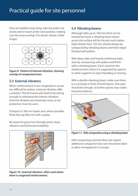
5.4 Vibrating beamsAlthough slabs up to 100 mm thick can be tamped by hand, a vibrating beam drawn across the surface will do the job much better. Slabs thicker than 150 mm should always be compacted by vibrating beams and their edges fi nished with pokers.
With deep slabs and heavily reinforced slabs, start by compacting with pokers and fi nish with a vibrating beam. Don’t stand on the reinforcement unless it is supported by spacers or other supports to stop it bending or moving.
With a double vibrating beam, make sure there is a surcharge in front of both beams. One pass should be enough, as further passes may create excessive laitance.
Figure 11. Slab compaction using a vibrating beam
Self-compacting concrete does not require additional compaction but care should be taken to allow entrapped air to escape.
Practical guide for site personnel
15
Compacting concrete
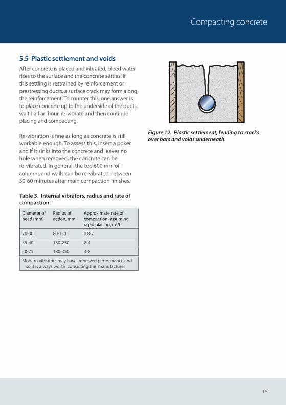
5.5 Plastic settlement and voidsAfter concrete is placed and vibrated, bleed water rises to the surface and the concrete settles. If this settling is restrained by reinforcement or prestressing ducts, a surface crack may form along the reinforcement. To counter this, one answer is to place concrete up to the underside of the ducts, wait half an hour, re-vibrate and then continue placing and compacting.
Re-vibration is fi ne as long as concrete is still workable enough. To assess this, insert a poker and if it sinks into the concrete and leaves no hole when removed, the concrete can bere-vibrated. In general, the top 600 mm of columns and walls can be re-vibrated between 30-60 minutes after main compaction fi nishes.
Table 3. Internal vibrators, radius and rate of compaction.
Diameter of head (mm)
Radius of action, mm
Approximate rate ofcompaction, assuming rapid placing, m3/h
20-30 80-150 0.8-2
35-40 130-250 2-4
50-75 180-350 3-8
Modern vibrators may have improved performance and so it is always worth consulting the manufacturer
Figure 12. Plastic settlement, leading to cracks over bars and voids underneath.
16
Practical guide for site personnel
6. Finishing concrete6.1 GeneralFinishing concrete correctly is a key factor in achieving the in-situ strength and performance characteristics. Good workmanship and the type of formwork used are vital to ensure that the bestfinish is achieved. For unformed surfaces the type of finish will depend on factors such as loading and resistance to impact, abrasion and chemicals.
6.2 Formed surface finishesThere are many types of formed finish. These include: as struck direct from formwork giving plain and smooth finishes, board-marked or ribbed surfaces produced directly from textured or profiled form-faces, and finishes produced indirectly after formwork removal which may include exposed aggregates or tooled finishes.
Any difference in the texture or permeability of the formwork surface will lead to variations in colour. Colour variation will also occur if the release agent has not be applied evenly. Formwork joints must be sealed to prevent leakage.
Care and attention should be given to formwork; checking for alignment levels, tightness of fixings and sealing of joints. The first concrete discharged from a truck-mixer should not be placed against formwork where a high quality finish is required. Spray-on curing membranes rather than damp hessian are the preferred curing method for high-quality concrete.
An exposed aggregate finish may be achieved by abrasive blasting using compressed air or high pressure water, normally after two-days.
Tooled finishes should not be produced until the concrete has achieved a compressive strength of at least 20 N/mm2. This involves removing 5 mm of surface concrete by bush hammering or 10 – 20 mm with point tooling. Applying a tooled finish to hardened concrete means exposure to noise, vibration and dust where it is essential that the correct personal protective equipment is used.
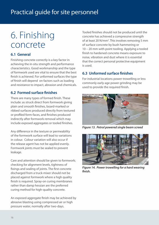
6.3 Unformed surface finishesFor industrial locations power-trowelling or less commonly early-age power grinding may be used to provide the required finish.
Figure 13. Petrol powered single beam screed
Figure 14. Power trowelling for a hard wearing finish.
17
Finishing concrete
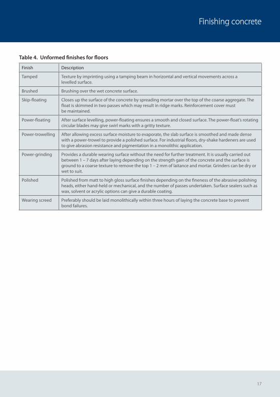
Table 4. Unformed finishes for floors
Finish Description
Tamped Texture by imprinting using a tamping beam in horizontal and vertical movements across a levelled surface.
Brushed Brushing over the wet concrete surface.
Skip-floating Closes up the surface of the concrete by spreading mortar over the top of the coarse aggregate. The float is skimmed in two passes which may result in ridge marks. Reinforcement cover must be maintained.
Power-floating After surface levelling, power-floating ensures a smooth and closed surface. The power-float’s rotating circular blades may give swirl marks with a gritty texture.
Power-trowelling After allowing excess surface moisture to evaporate, the slab surface is smoothed and made dense with a power-trowel to provide a polished surface. For industrial floors, dry-shake hardeners are used to give abrasion resistance and pigmentation in a monolithic application.
Power-grinding Provides a durable wearing surface without the need for further treatment. It is usually carried out between 1 – 7 days after laying depending on the strength gain of the concrete and the surface is ground to a coarse texture to remove the top 1 – 2 mm of laitance and mortar. Grinders can be dry or wet to suit.
Polished Polished from matt to high gloss surface finishes depending on the fineness of the abrasive polishing heads, either hand-held or mechanical, and the number of passes undertaken. Surface sealers such as wax, solvent or acrylic options can give a durable coating.
Wearing screed Preferably should be laid monolithically within three hours of laying the concrete base to prevent bond failures.
18
Practical guide for site personnel
7. Curing concrete7.1 GeneralProper curing is the process of preventing the loss of moisture from the concrete whilst maintaining a satisfactory temperature in the concrete. Concrete cured and protected well in its early life minimises the risk of plastic shrinkage cracking and enhances surface strength, abrasion resistance and resistance to impact damage.
Moist curing is readily achieved by covering with a polythene sheet or using a sprayed membrane. For formed surfaces leaving the formwork is eff ective provided the formwork is not needed for immediate re-use. The exposed surfaces of slabs are particularly vulnerable to poor curing where moderate sunshine or light winds will mean premature drying.
Curing should always start before the concrete begins to dry out and continue for a period depending on the strength gain of the concrete. This process should be closely monitored throughout.
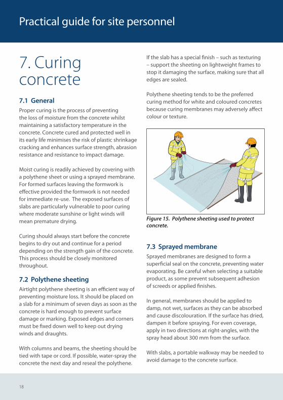
7.2 Polythene sheetingAirtight polythene sheeting is an effi cient way of preventing moisture loss. It should be placed on a slab for a minimum of seven days as soon as theconcrete is hard enough to prevent surface damage or marking. Exposed edges and corners must be fi xed down well to keep out drying winds and draughts.
With columns and beams, the sheeting should be tied with tape or cord. If possible, water-spray the concrete the next day and reseal the polythene.
If the slab has a special fi nish – such as texturing – support the sheeting on lightweight frames to stop it damaging the surface, making sure that alledges are sealed.
Polythene sheeting tends to be the preferred curing method for white and coloured concretes because curing membranes may adversely aff ect colour or texture.
Figure 15. Polythene sheeting used to protect concrete.
7.3 Sprayed membraneSprayed membranes are designed to form a superfi cial seal on the concrete, preventing water evaporating. Be careful when selecting a suitable product, as some prevent subsequent adhesion of screeds or applied fi nishes.
In general, membranes should be applied to damp, not wet, surfaces as they can be absorbed and cause discolouration. If the surface has dried, dampen it before spraying. For even coverage, apply in two directions at right-angles, with the spray head about 300 mm from the surface.
With slabs, a portable walkway may be needed to avoid damage to the concrete surface.
19
Curing concrete
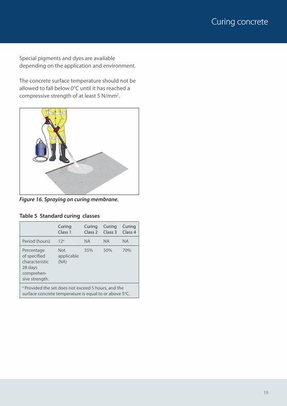
Special pigments and dyes are available depending on the application and environment.
The concrete surface temperature should not be allowed to fall below 0°C until it has reached a compressive strength of at least 5 N/mm2.
Figure 16. Spraying on curing membrane.
Table 5 Standard curing classes
Curing Class 1
Curing Class 2
Curing Class 3
Curing Class 4
Period (hours) 12a NA NA NA
Percentageof specifi edcharacteristic28 dayscomprehen-sive strength.
Not applicable (NA)
35% 50% 70%
a Provided the set does not exceed 5 hours, and thesurface concrete temperature is equal to or above 5oC.

20
Practical guide for site personnel
Sampling, testing and making specimens for strength testsAppendix A: Sampling
Appendix B: Consistence testing
Appendix C: Air content testing
Appendix D: Specimens for strength tests
22
Practical guide for site personnel
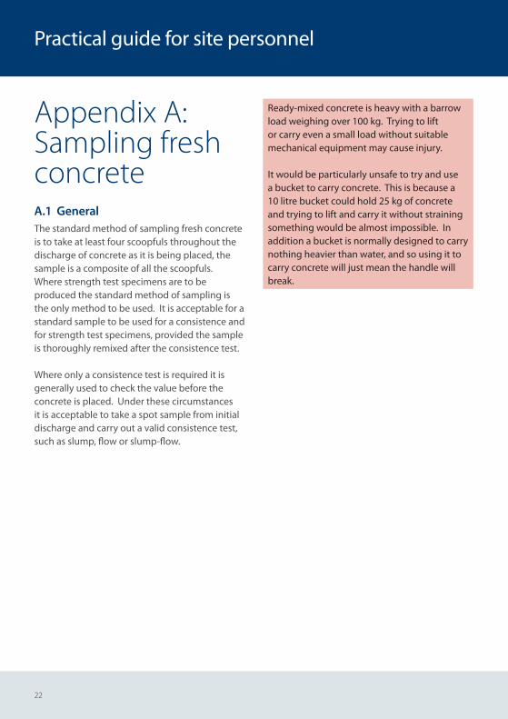
Appendix A: Sampling fresh concreteA.1 GeneralThe standard method of sampling fresh concrete is to take at least four scoopfuls throughout the discharge of concrete as it is being placed, the sample is a composite of all the scoopfuls. Where strength test specimens are to be produced the standard method of sampling is the only method to be used. It is acceptable for a standard sample to be used for a consistence and for strength test specimens, provided the sample is thoroughly remixed after the consistence test. Where only a consistence test is required it is generally used to check the value before the concrete is placed. Under these circumstances it is acceptable to take a spot sample from initial discharge and carry out a valid consistence test, such as slump, flow or slump-flow.
Ready-mixed concrete is heavy with a barrow load weighing over 100 kg. Trying to lift or carry even a small load without suitable mechanical equipment may cause injury.
It would be particularly unsafe to try and use a bucket to carry concrete. This is because a 10 litre bucket could hold 25 kg of concrete and trying to lift and carry it without straining something would be almost impossible. In addition a bucket is normally designed to carry nothing heavier than water, and so using it to carry concrete will just mean the handle will break.
23
Sampling fresh concrete
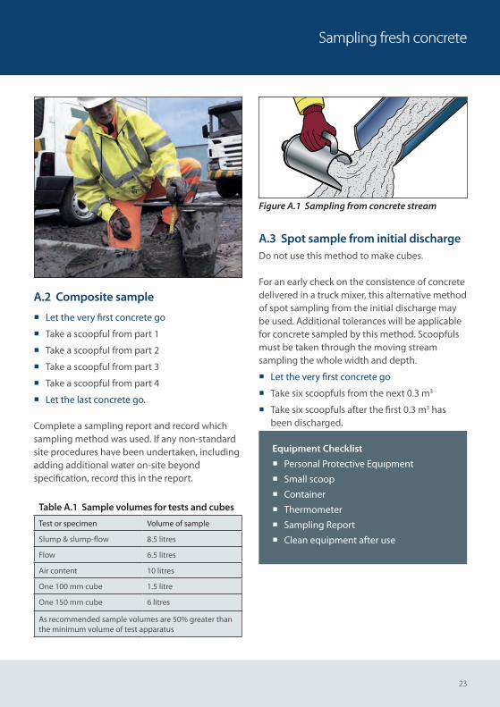
A.2 Composite sample
¡ Let the very fi rst concrete go
¡ Take a scoopful from part 1
¡ Take a scoopful from part 2
¡ Take a scoopful from part 3
¡ Take a scoopful from part 4
¡ Let the last concrete go.
Complete a sampling report and record which sampling method was used. If any non-standard site procedures have been undertaken, including adding additional water on-site beyond specifi cation, record this in the report.
Figure A.1 Sampling from concrete stream
A.3 Spot sample from initial dischargeDo not use this method to make cubes.
For an early check on the consistence of concrete delivered in a truck mixer, this alternative method of spot sampling from the initial discharge may be used. Additional tolerances will be applicable for concrete sampled by this method. Scoopfuls must be taken through the moving stream sampling the whole width and depth.
¡ Let the very fi rst concrete go
¡ Take six scoopfuls from the next 0.3 m3
¡ Take six scoopfuls after the fi rst 0.3 m3 has been discharged.
Equipment Checklist
¡ Personal Protective Equipment
¡ Small scoop
¡ Container
¡ Thermometer
¡ Sampling Report
¡ Clean equipment after use
Table A.1 Sample volumes for tests and cubes
Test or specimen Volume of sample
Slump & slump-fl ow 8.5 litres
Flow 6.5 litres
Air content 10 litres
One 100 mm cube 1.5 litre
One 150 mm cube 6 litres
As recommended sample volumes are 50% greater than the minimum volume of test apparatus
24
Practical guide for site personnel
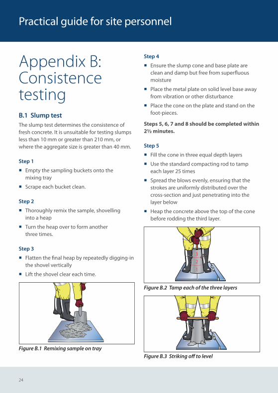
Appendix B:Consistence testingB.1 Slump testThe slump test determines the consistence of fresh concrete. It is unsuitable for testing slumps less than 10 mm or greater than 210 mm, or where the aggregate size is greater than 40 mm.
Step 1
¡ Empty the sampling buckets onto themixing tray
¡ Scrape each bucket clean.
Step 2
¡ Thoroughly remix the sample, shovellinginto a heap
¡ Turn the heap over to form anotherthree times.
Step 3
¡ Flatten the fi nal heap by repeatedly digging-in the shovel vertically
¡ Lift the shovel clear each time.
Figure B.1 Remixing sample on tray
Step 4
¡ Ensure the slump cone and base plate are clean and damp but free from superfl uous moisture
¡ Place the metal plate on solid level base away from vibration or other disturbance
¡ Place the cone on the plate and stand on the foot-pieces.
Steps 5, 6, 7 and 8 should be completed within 2½ minutes.
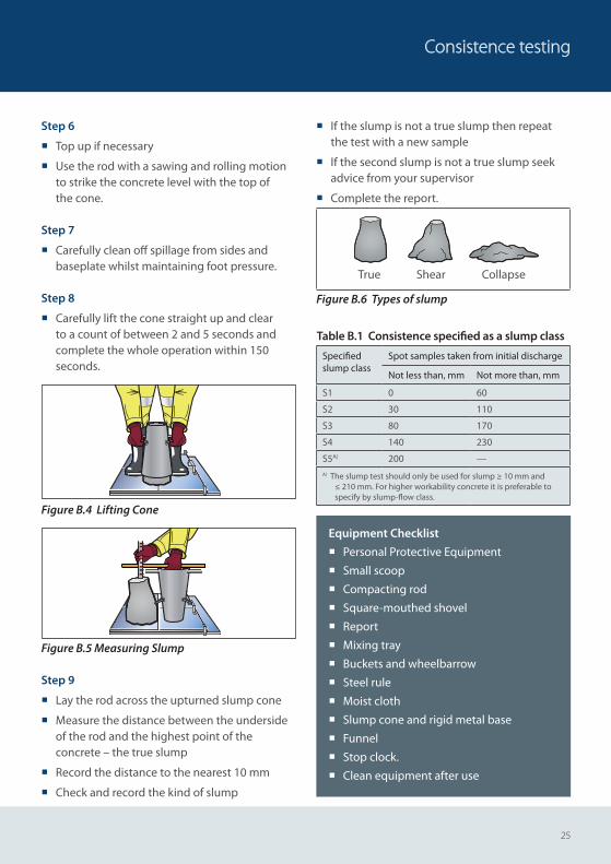
Step 5
¡ Fill the cone in three equal depth layers
¡ Use the standard compacting rod to tamp each layer 25 times
¡ Spread the blows evenly, ensuring that the strokes are uniformly distributed over the cross-section and just penetrating into the layer below
¡ Heap the concrete above the top of the cone before rodding the third layer.
3
2
1
Figure B.2 Tamp each of the three layers
Figure B.3 Striking off to level
25
Consistence testing
Step 6
¡ Top up if necessary
¡ Use the rod with a sawing and rolling motion to strike the concrete level with the top ofthe cone.
Step 7
¡ Carefully clean off spillage from sides and baseplate whilst maintaining foot pressure.
Step 8
¡ Carefully lift the cone straight up and clear to a count of between 2 and 5 seconds and complete the whole operation within 150 seconds.
Figure B.4 Lifting Cone
Figure B.5 Measuring Slump
Step 9
¡ Lay the rod across the upturned slump cone
¡ Measure the distance between the underside of the rod and the highest point of the concrete – the true slump
¡ Record the distance to the nearest 10 mm
¡ Check and record the kind of slump
¡ If the slump is not a true slump then repeat the test with a new sample
¡ If the second slump is not a true slump seek advice from your supervisor
¡ Complete the report.
True Shear Collapse
Figure B.6 Types of slump
Table B.1 Consistence specifi ed as a slump class
Specifi ed slump class
Spot samples taken from initial discharge
Not less than, mm Not more than, mm
S1 0 60
S2 30 110
S3 80 170
S4 140 230
S5A) 200 —A) The slump test should only be used for slump ≥ 10 mm and
≤ 210 mm. For higher workability concrete it is preferable to specify by slump-fl ow class.
Equipment Checklist
¡ Personal Protective Equipment
¡ Small scoop
¡ Compacting rod
¡ Square-mouthed shovel
¡ Report
¡ Mixing tray
¡ Buckets and wheelbarrow
¡ Steel rule
¡ Moist cloth
¡ Slump cone and rigid metal base
¡ Funnel
¡ Stop clock.
¡ Clean equipment after use
26
B.2 Flow TestThe Flow Table test specifi es a method for determining the fl ow of fresh concrete between 340 – 600 mm. It is not applicable to self-compacting concrete, foamed concrete or no-fi nes concrete, or concrete with a maximum aggregate size exceeding 63 mm.
First fi nd a suitable location for the fl ow table. It must be placed on a fi rm, fl at and level surface. It may be necessary to prepare an area for the table.
Step 1
¡ Empty the sampling buckets onto themixing tray
¡ Scrape each bucket clean.
Step 2
¡ Thoroughly remix the sample, shovellinginto a heap
¡ Turn the heap over to form another three times.
Step 3
¡ Flatten the fi nal heap by repeatedly digging-in the shovel vertically
¡ Lift the shovel clear each time
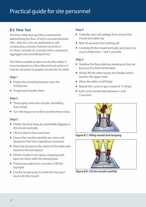
¡ Ensure the mould and table are clean and damp but free from superfl uous moisture
¡ Place the mould on the centre of the table and stand on the foot-pieces
¡ Fill the mould in two layers, tamping each layer ten times with the tamping bar
¡ If necessary add more concrete to fi ll thetop layer
¡ Use the tamping bar to strike the top layer level with the mould.
Step 4
¡ Carefully clean off spillage from around the mould and table top
¡ Wait 30 seconds from striking off
¡ Carefully lift the mould vertically and clear to a count of between 1 and 3 seconds.
Step 5
¡ Stabilise the fl ow table by standing on the toe board at the front of the table
¡ Slowly lift the table top by the handle until it reaches the upper stop
¡ Allow the table to fall freely
¡ Repeat this cycle to give a total of 15 drops
¡ Each cycle should take between 1 and3 seconds.
21
Figure B.7 Filling mould and tamping
Figure B.8 Lift the mould carefully
Practical guide for site personnel
27
Consistence testing
Table B.2 Consistence specifi ed as a fl ow class
Flow class Spot samples taken from initial discharge
Not less than, mm Not more than, mm
F1A) 0 360
F2 330 430
F3 400 500
F4 470 570
F5 540 640
F6A) 610 —
A) The fl ow test should only be used for fl ow ≥ 340 mm and ≤ 620 mm. For higher work-ability concrete it is preferable to specify by slump-fl ow class.
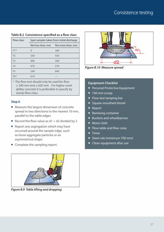
Step 6
¡ Measure the largest dimension of concrete spread in two directions to the nearest 10 mm, parallel to the table edges
¡ Record the fl ow value as d1 + d2 divided by 2
¡ Report any segregation which may have occurred around the sample edge, suchas loose aggregate particles or an asymmetrical shape
¡ Complete the sampling report.
Figure B.9 Table lifting and dropping
d1
Figure B.10 Measure spread
Equipment Checklist
¡ Personal Protective Equipment
¡ 100 mm scoop
¡ Flow-test tamping bar
¡ Square-mouthed shovel
¡ Report
¡ Remixing container
¡ Buckets and wheelbarrow
¡ Moist cloth
¡ Flow table and fl ow cone
¡ Timer
¡ Steel rule (minimum 700 mm)
¡ Clean equipment after use
28
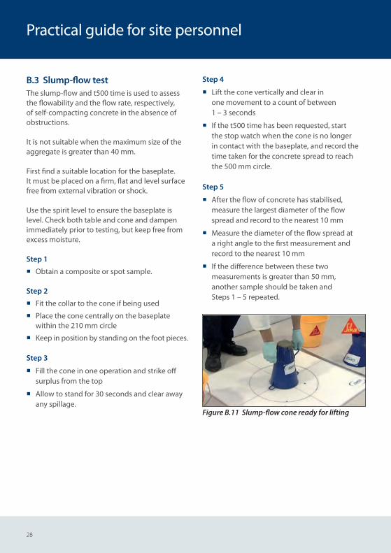
B.3 Slump-flow testThe slump-flow and t500 time is used to assess the flowability and the flow rate, respectively, of self-compacting concrete in the absence of obstructions.
It is not suitable when the maximum size of the aggregate is greater than 40 mm.
First find a suitable location for the baseplate. It must be placed on a firm, flat and level surface free from external vibration or shock.
Use the spirit level to ensure the baseplate is level. Check both table and cone and dampen immediately prior to testing, but keep free from excess moisture.
Step 1
¡ Obtain a composite or spot sample.
Step 2
¡ Fit the collar to the cone if being used
¡ Place the cone centrally on the baseplate within the 210 mm circle
¡ Keep in position by standing on the foot pieces.
Step 3
¡ Fill the cone in one operation and strike off surplus from the top
¡ Allow to stand for 30 seconds and clear away any spillage.
Step 4
¡ Lift the cone vertically and clear in one movement to a count of between 1 – 3 seconds
¡ If the t500 time has been requested, start the stop watch when the cone is no longer in contact with the baseplate, and record the time taken for the concrete spread to reach the 500 mm circle.
Step 5
¡ After the flow of concrete has stabilised, measure the largest diameter of the flow spread and record to the nearest 10 mm
¡ Measure the diameter of the flow spread at a right angle to the first measurement and record to the nearest 10 mm
¡ If the difference between these two measurements is greater than 50 mm, another sample should be taken and Steps 1 – 5 repeated.
Figure B.11 Slump-flow cone ready for lifting
Practical guide for site personnel
29
Consistence testing
Step 6
¡ Complete the Test Report, including ; sample identification, date and time, slump-flow, t500, indication of segregation, deviation from standard test method, age and temperature of concrete and declaration of responsibility.
Please note:
¡ Check for signs of segregation may include a ring of cement paste and segregated coarse aggregate within the central area
¡ This test is not suitable if two consecutive tests fail.
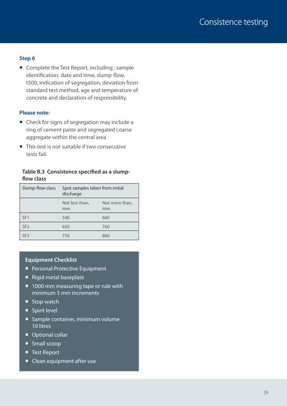
Table B.3 Consistence specified as a slump-flow class
Slump-flow class Spot samples taken from initial discharge
Not less than, mm
Not more than, mm
SF1 540 660
SF2 650 760
SF3 750 860
Equipment Checklist
¡ Personal Protective Equipment
¡ Rigid metal baseplate
¡ 1000 mm measuring tape or rule with minimum 5 mm increments
¡ Stop watch
¡ Spirit level
¡ Sample container, minimum volume 10 litres
¡ Optional collar
¡ Small scoop
¡ Test Report
¡ Clean equipment after use
30
Practical guide for site personnel
B.4 Consistence retention testingSometimes there are requirements for consistence retention times well in excess of that required to place and compact concrete. Where there is such a requirement the method by which consistence is measured should be specified as well as the necessary details for transporting, handling, care and remixing of samples. The containers used for holding the samples should be stored near the point of discharge but protected from direct sunlight. Where there is a specified requirement for consistence retention, e.g. a flow of 450 mm at 5 hours, this requirement should be tested on a sample not used previously, stored in a single container and remixed prior to testing at the specified time.
The difference between standard consistence test results and those obtained from stored and remixed samples is unknown. Due to the potential for moisture and grout loss from stored samples, consideration should be given to increasing the acceptable range of consistence test results.
It may be possible to measure the loss of consistence with time by re-testing a single large sample. Such testing might provide an indication of the concrete’s performance but the results should not be used for conformity assessment.
Containers and sample sizeContainers for storing concrete for delayed testing should be sealable cylindrical containers made from non-absorbent material not readily attacked by cement paste. To minimize the potential loss of mortar, the ratio of height to diameter should be not less than 0.7 or greater than 1.3. The size of the container shall be such that, when filled, the top surface of the concrete shall be within 25 mm to 50 mm of the container
lid. Plastic tubs used for cement storage have been found to be suitable.
For consistence retention testing of single samples the sample should be at least 1.5 times the quantity estimated as being required for the test.
Temperature and test reportThe temperature of the concrete sample and ambient temperature should be recorded at the time of consistence testing. The test report shall include a summary of the delayed testing procedures as well as a record of the consistence test results, temperatures, date and time of testing.
31
Air content tests
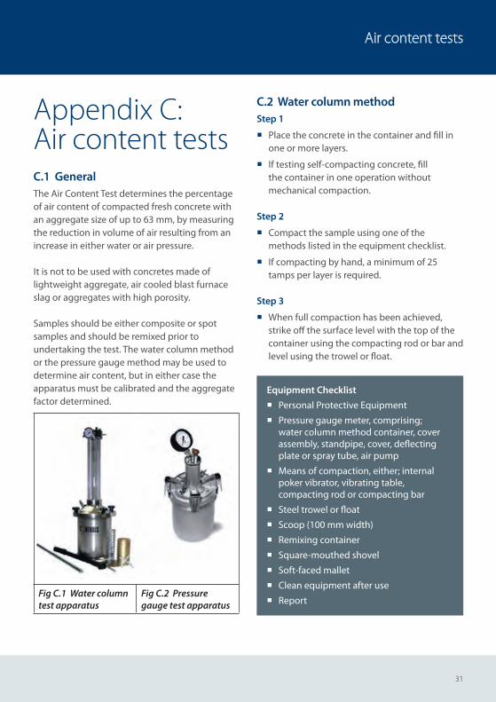
Appendix C: Air content testsC.1 GeneralThe Air Content Test determines the percentage of air content of compacted fresh concrete with an aggregate size of up to 63 mm, by measuring the reduction in volume of air resulting from an increase in either water or air pressure.
It is not to be used with concretes made of lightweight aggregate, air cooled blast furnace slag or aggregates with high porosity.
Samples should be either composite or spot samples and should be remixed prior to undertaking the test. The water column method or the pressure gauge method may be used to determine air content, but in either case the apparatus must be calibrated and the aggregate factor determined.
Fig C.1 Water column test apparatus
Fig C.2 Pressure gauge test apparatus
C.2 Water column methodStep 1
¡ Place the concrete in the container and fill in one or more layers.
¡ If testing self-compacting concrete, fill the container in one operation without mechanical compaction.
Step 2
¡ Compact the sample using one of the methods listed in the equipment checklist.
¡ If compacting by hand, a minimum of 25 tamps per layer is required.
Step 3
¡ When full compaction has been achieved, strike off the surface level with the top of the container using the compacting rod or bar and level using the trowel or float.
Equipment Checklist
¡ Personal Protective Equipment
¡ Pressure gauge meter, comprising; water column method container, cover assembly, standpipe, cover, deflecting plate or spray tube, air pump
¡ Means of compaction, either; internal poker vibrator, vibrating table, compacting rod or compacting bar
¡ Steel trowel or float
¡ Scoop (100 mm width)
¡ Remixing container
¡ Square-mouthed shovel
¡ Soft-faced mallet
¡ Clean equipment after use
¡ Report
32
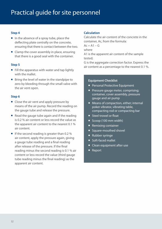
Step 4
¡ In the absence of a spray tube, place the deflecting plate centrally on the concrete, ensuring that there is contact between the two.
¡ Clamp the cover assembly in place, ensuring that there is a good seal with the container.
Step 5
¡ Fill the apparatus with water and tap lightly with the mallet.
¡ Bring the level of water in the standpipe to zero by bleeding through the small valve with the air vent open.
Step 6
¡ Close the air vent and apply pressure by means of the air pump. Record the reading on the gauge tube and release the pressure.
¡ Read the gauge tube again and if the reading is 0.2 % air content or less record the value as the apparent air content to the nearest 0.1 % air content.
¡ If the second reading is greater than 0.2 % air content, apply the pressure again, giving a gauge tube reading and a final reading after release of the pressure. If the final reading minus the second reading is 0.1 % air content or less record the value (third gauge tube reading minus the final reading) as the apparent air content.
CalculationCalculate the air content of the concrete in the container, Ac, from the formula:Ac = A1 – GwhereA1 is the apparent air content of the sample tested;G is the aggregate correction factor. Express the air content as a percentage to the nearest 0.1 %.
Practical guide for site personnel
Equipment Checklist
¡ Personal Protective Equipment
¡ Pressure gauge meter, comprising; container, cover assembly, pressure gauge and air pump
¡ Means of compaction, either; internal poker vibrator, vibrating table, compacting rod or compacting bar
¡ Steel trowel or float
¡ Scoop (100 mm width)
¡ Remixing container
¡ Square-mouthed shovel
¡ Rubber syringe
¡ Soft-faced mallet
¡ Clean equipment after use
¡ Report
33
Air content tests
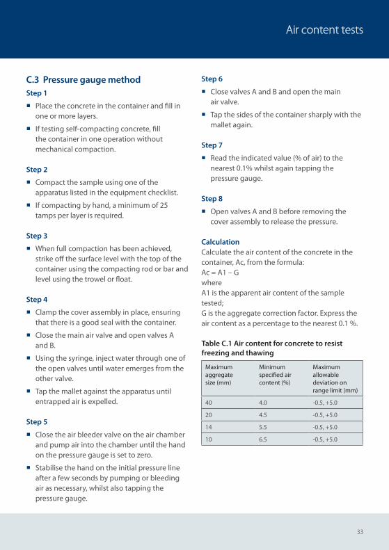
C.3 Pressure gauge methodStep 1
¡ Place the concrete in the container and fill in one or more layers.
¡ If testing self-compacting concrete, fill the container in one operation without mechanical compaction.
Step 2
¡ Compact the sample using one of the apparatus listed in the equipment checklist.
¡ If compacting by hand, a minimum of 25 tamps per layer is required.
Step 3
¡ When full compaction has been achieved, strike off the surface level with the top of the container using the compacting rod or bar and level using the trowel or float.
Step 4
¡ Clamp the cover assembly in place, ensuring that there is a good seal with the container.
¡ Close the main air valve and open valves A and B.
¡ Using the syringe, inject water through one of the open valves until water emerges from the other valve.
¡ Tap the mallet against the apparatus until entrapped air is expelled.
Step 5
¡ Close the air bleeder valve on the air chamber and pump air into the chamber until the hand on the pressure gauge is set to zero.
¡ Stabilise the hand on the initial pressure line after a few seconds by pumping or bleeding air as necessary, whilst also tapping the pressure gauge.
Step 6
¡ Close valves A and B and open the main air valve.
¡ Tap the sides of the container sharply with the mallet again.
Step 7
¡ Read the indicated value (% of air) to the nearest 0.1% whilst again tapping the pressure gauge.
Step 8
¡ Open valves A and B before removing the cover assembly to release the pressure.
CalculationCalculate the air content of the concrete in the container, Ac, from the formula:Ac = A1 – GwhereA1 is the apparent air content of the sample tested;G is the aggregate correction factor. Express the air content as a percentage to the nearest 0.1 %.
Table C.1 Air content for concrete to resist freezing and thawing
Maximum aggregate size (mm)
Minimum specified air content (%)
Maximum allowable deviation on range limit (mm)
40 4.0 -0.5, +5.0
20 4.5 -0.5, +5.0
14 5.5 -0.5, +5.0
10 6.5 -0.5, +5.0
34
Practical guide for site personnel
Appendix D:Strength test specimensD.1 GeneralCubes can only be made from composite samples. This section covers the preparation and filling of moulds, compaction of the concrete, levelling the surface, curing of test specimens and transporting test specimens.
D.2 Cube specimens, normal consistence concreteStep 1
¡ Thoroughly remix the sample using the remixing container and square- mouthed shovel
¡ Check that the moulds are clean and lightly oiled with all bolts tightened so that there will be no leakage
¡ Ensure that the correct halves of the moulds are used and that the corner lifting pins are correctly located.
Step 2
¡ For concretes with a slump class S1 or S2, fill the mould with concrete in 50 mm layers. Using the compacting bar or rod, compact the concrete with no fewer than 25 tamps for each of the two layers in a 100 mm mould and no fewer than 35 tamps for each of the three layers in a 150 mm mould
¡ For concrete with a consistence other than S1 or S2 the moulds shall be filled in one or more layers to achieve full compaction.
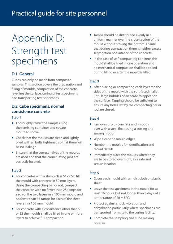
¡ Tamps should be distributed evenly in a uniform manner over the cross-section of the mould without striking the bottom. Ensure that during compaction there is neither excess segregation nor laitance of the concrete.
¡ In the case of self-compacting concrete, the mould shall be filled in one operation and no mechanical compaction shall be applied during filling or after the mould is filled.
Step 3
¡ After placing or compacting each layer tap the sides of the mould with the soft-faced mallet until large bubbles of air cease to appear on the surface. Tapping should be sufficient to ensure any holes left by the compacting bar or rod are closed.
Step 4
¡ Remove surplus concrete and smooth over with a steel float using a cutting and sawing motion
¡ Wipe clean the mould edges
¡ Number the moulds for identification and record details.
¡ Immediately place the moulds where they are to be stored overnight, in a safe and secure location.
Step 5
¡ Cover each mould with a moist cloth or plastic sheet
¡ Leave the test specimens in the mould for at least 16 hours, but not longer than 3 days, at a temperature of 20 ± 5 °C.
¡ Protect against shock, vibration and dehydration particularly where specimens are transported from site to the curing facility.
¡ Complete the sampling and cube making reports.
35
Strength test specimens
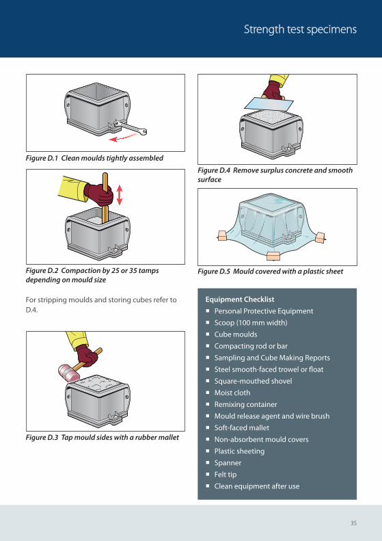
Figure D.1 Clean moulds tightly assembled
Figure D.2 Compaction by 25 or 35 tamps depending on mould size
For stripping moulds and storing cubes refer to D.4.
Figure D.3 Tap mould sides with a rubber mallet
Figure D.4 Remove surplus concrete and smooth surface
Figure D.5 Mould covered with a plastic sheet
Equipment Checklist
¡ Personal Protective Equipment
¡ Scoop (100 mm width)
¡ Cube moulds
¡ Compacting rod or bar
¡ Sampling and Cube Making Reports
¡ Steel smooth-faced trowel or fl oat
¡ Square-mouthed shovel
¡ Moist cloth
¡ Remixing container
¡ Mould release agent and wire brush
¡ Soft-faced mallet
¡ Non-absorbent mould covers
¡ Plastic sheeting
¡ Spanner
¡ Felt tip
¡ Clean equipment after use
36
Practical guide for site personnel
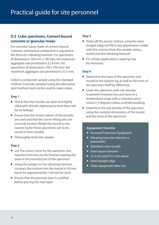
D.3 Cube specimens, Cement bound concrete or granular mixesFor concrete cubes made of cement-bound mixtures, mechanical compaction is required in the form of a vibrating hammer. For specimens of dimensions 100 mm x 100 mm, the maximum aggregate size permitted is 22.4 mm. For specimens of dimensions 150 x 150 mm, the maximum aggregate size permitted is 31.5 mm.
Collect a composite sample using the standard method. Concrete sampled using the alternative spot method must not be used to make cubes.
Step 1
¡ Check that the moulds are clean and lightly oiled with all bolts tightened so that there will be no leakage
¡ Ensure that the correct halves of the moulds are used and that the corner lifting pins are correctly located. Weigh the mould to the nearest 5g for those specimens not to be stored in their moulds.
¡ Thoroughly remix the sample.
Step 2
¡ Use the correct sieve for the specimen size required and only use the fraction passing the sieve in the manufacture of the specimen
¡ Using the tamper on the vibrating hammer, compact the mixture into the mould in 50 mm layers for approximately 1 minute for each.
¡ Ensure that the previous layer is scarified before placing the next layer.
Step 3
¡ Strike off the excess mixture using the steel straight edge and fill in any depressions visible with fine mixture from the sample using a trowel and the vibrating hammer.
¡ For certain applications, capping may be necessary.
Step 4
¡ Determine the mass of the specimen and mould to the nearest 5g, as well as the mass of the specimen itself by difference.
¡ Cover the specimen with wet hessian to prevent moisture loss and store at a temperature range with a tolerance plus/minus 2-5 degrees Celsius until demoulding.
¡ Determine the wet density of the specimen using the nominal dimensions of the mould and the mass of the specimen.
Equipment Checklist
¡ Personal Protective Equipment
¡ Vibrating hammer (electric or pneumatic)
¡ Standard cube moulds
¡ Steel square tampers
¡ 22.5 mm and 31.5 mm sieves
¡ Steel straight edge
¡ Clean equipment after use
37
Strength test specimens
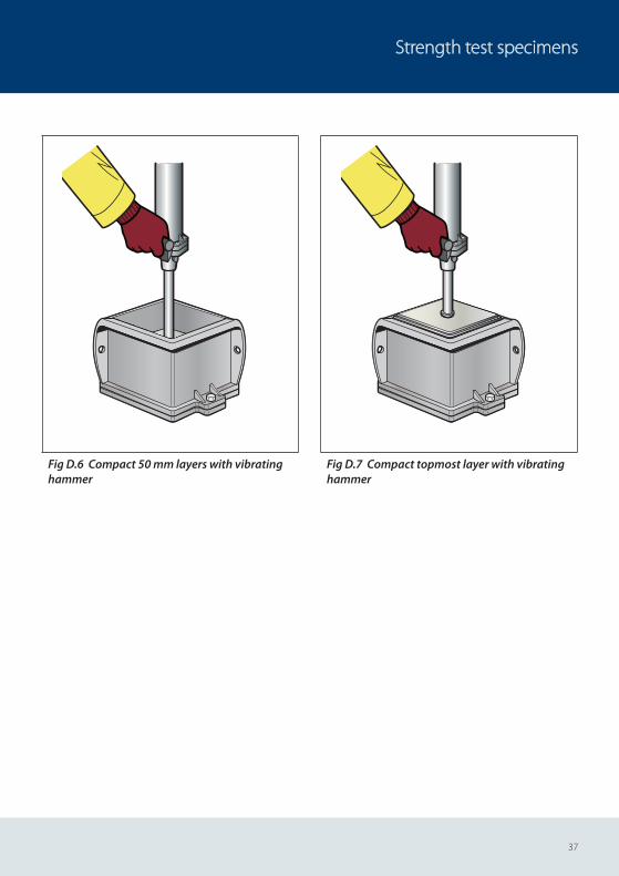
Fig D.6 Compact 50 mm layers with vibrating hammer
Fig D.7 Compact topmost layer with vibrating hammer
38
Practical guide for site personnel
D.4 Stripping and storingStep 1
¡ Having stored the moulds at between 15-25°C, the cubes should be removed from the moulds between 16 – 72 hours after casting.
¡ Record the minimum and maximum overnight storage temperatures on the sampling report.
Step 2
¡ Slacken all nuts
¡ Part the sides of the mould, tapping gently with the soft-faced mallet
¡ Lift off carefully
¡ Remember new cubes are easily damaged so handle with care.
Step 3
¡ Mark each cube with its identifi cation number on two of its cast sides and make a visual inspection of the cube.
Step 4 – Either:a) place the cubes in the curing tank or where
the water temperature is controlled at 20°C ± 2°C, ensuring that each cube remains fully submersed, or
b) place the cubes in a curing room or chamber where the temperature is controlled at 20°C ± 2°C and the relative humidity is maintained at equal to or greater than 95%, or
c) transport the cubes to the testing laboratory with a 72 hour period
Step 5
¡ Clean and reassemble the moulds, using the mould release agent ready for the next time the cube is used
¡ Ensure that the power supply is not turned off day or night
¡ Check and record the temperature range daily using the minimum/maximum thermometer.
Please Note:
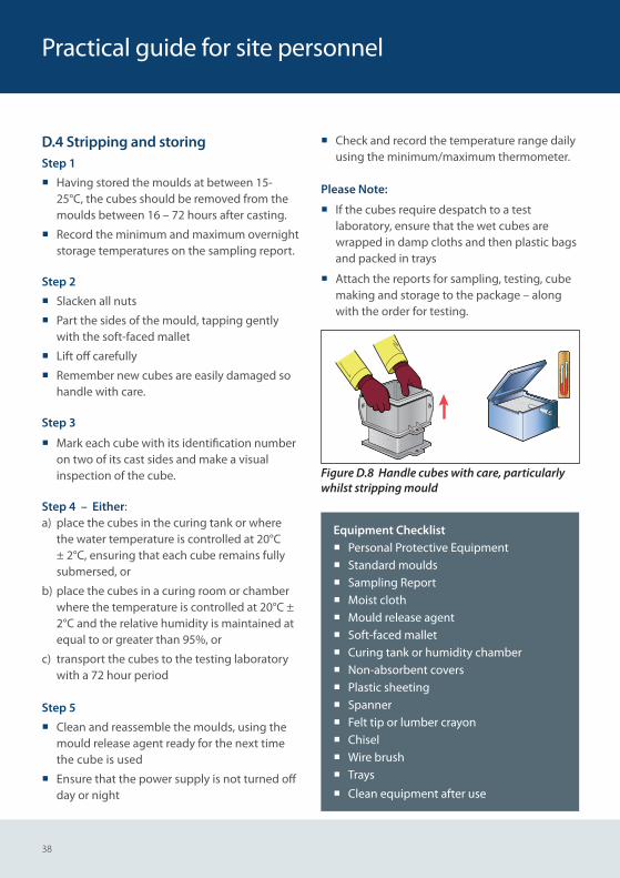
¡ If the cubes require despatch to a test laboratory, ensure that the wet cubes are wrapped in damp cloths and then plastic bags and packed in trays
¡ Attach the reports for sampling, testing, cube making and storage to the package – along with the order for testing.
Figure D.8 Handle cubes with care, particularly whilst stripping mould
Equipment Checklist ¡ Personal Protective Equipment ¡ Standard moulds ¡ Sampling Report ¡ Moist cloth ¡ Mould release agent ¡ Soft-faced mallet ¡ Curing tank or humidity chamber ¡ Non-absorbent covers ¡ Plastic sheeting ¡ Spanner ¡ Felt tip or lumber crayon ¡ Chisel ¡ Wire brush ¡ Trays
¡ Clean equipment after use
39
Standards
Standards1. BRITISH STANDARDS INSTITUTION, BS 8500-
1:2015+A1:2016. Concrete – Complementary British Standard to BS EN 206. Part 1: Method of specifying and guidance for the specifier. BSI, London, August 2016.
2. BRITISH STANDARDS INSTITUTION, BS 8500-2:2015+A1:2016. Concrete – Complementary British Standard to BS EN 206. Part 2: Specification for constituent materials and concrete. BSI, London, May 2016.
3. BRITISH STANDARDS INSTITUTION, BS EN 206: 2013+A1:2016. Concrete – Specification, performance, production and conformity. BSI, London, November 2016.
4. BRITISH STANDARDS INSTITUTION, BS EN 13670:2009. Execution of concrete structures. Specification, performance, production and conformity. BSI, London, February 2010.
5. BRITISH STANDARDS INSTITUTION, BS EN 12350-1: 2009. Testing fresh concrete. Part 1: Sampling. BSI, London, August 2009.
6. BRITISH STANDARDS INSTITUTION, BS EN 12350-2: 2009. Testing fresh concrete. Part 2: Slump-test. BSI, London, June 2009.
7. BRITISH STANDARDS INSTITUTION, BS EN 12350-5: 2009. Testing fresh concrete. Part 5: Flow table test. BSI, London, May 2009.
8. BRITISH STANDARDS INSTITUTION, BS EN 12350-7: 2009. Testing fresh concrete. Part 7: Air content – Pressure methods. BSI, London, May 2009.
9. BRITISH STANDARDS INSTITUTION, BS EN 12350-8: 2010. Testing fresh concrete. Part 8: Self-compacting concrete – Slump-flow test. BSI, London, August 2010.
10. BRITISH STANDARDS INSTITUTION, BS EN 12390-1: 2012. Testing hardened concrete. Part 1: Shape, dimensions and other requirements for specimens and moulds. BSI, London, November 2012.
11. BRITISH STANDARDS INSTITUTION, BS EN 12390-2: 2009. Testing hardened concrete. Part 2: Making and curing specimens for strength tests. BSI, London, September 2009.
12. BRITISH STANDARDS INSTITUTION BS EN 13286-4:2003. Unbound and hydraulically bound mixtures – Part 4. Test methods for laboratory reference density and water content. Vibrating hammer. BSI, London, March 2003.
13. BRITISH STANDARDS INSTITUTION, BS EN 13286-51: 2004. Unbound and hydraulically bound mixtures. Method for the manufacture of test specimens of hydraulically bound mixtures using vibrating hammer compaction. BSI, London, January 2005.

BRMCA is part of the Mineral Products Association, the trade association for the aggregates, asphalt, cement, concrete, dimension stone, lime, mortar and silica sand industries.
BRMCAGillingham House38 - 44 Gillingham StreetLondon SW1V 1HUTel +44 (0)20 7963 8000Fax +44 (0)20 7963 8001www.brmca.org.uk
All advice or information from The British Ready-Mixed Concrete Association is intended for those who will evaluate the significance and limitations of its contents and take responsibility for its use and application. No liability (including that for negligence) for any loss resulting from such advice or information is accepted. Readers should note that all BRMCA publications are subject to revision from time to time and shouldtherefore ensure that they are in possession of the latest version.
First Published 2017© MPA
BRMCA Members
Aggregate Industrieswww.aggregates.com
Batchmix Ltd, Rotherham Sand & Gravelwww.batchmix.co.uk
Breedon Aggregateswww.breedonaggregates.com
Brett Concretewww.brett.co.uk
CEMEX UKwww.cemex.co.uk
Cullimore Groupwww.cullimoregroup.co.uk
F M Conwaywww.fmconway.co.uk
Gallagher Groupwww.gallagher-group.co.uk
Hanson UKhansonready-mixconcrete.co.uk
Hills Quarry Products Ltdwww.hills-group.co.uk
J Clubb Ltdwww.jclubb.co.uk
Kendall Ready-Mixed Concrete, Kendall Groupwww.kendalls.co.uk
London Concretewww.aggregate.com
Morris & Perry Ltdwww.morrisandperry.co.uk
Quattro, ready mix concretewww.quattroukltd.co.uk
Readymix Huddersfield, Myers Groupwww.myersgroup.co.uk
Tarmac www.tarmac.com
Tuck-mix concrete, H Tuckwell & Sonswww.tuckwells.co.uk
Tudor Griffiths Groupwww.tgconcrete.co.uk
Affiliates
Bonnar Sand & Gravelwww.bonar.com
Hillhouse Quarry Group Ltdwww.hillhousegroup.co.uk
Northstone (NI)www.northstone-ni.co.uk
MPA Scotlandwww.mineralproducts.org
MPA Waleswww.mineralproducts.org
Quarry Products Association Northern Ireland (QPANI)www.qpani.org
Printed on recycled paper manufactured at a mill certified with ISO 14001 environmental management standard. The pulp used in this product is bleached using an Elemental Chlorine Free process. M
BL25
504-
2