Embed Size (px)
Citation preview
READSTAR SERIES OPERATOR’S MANUAL
1
ReadStar SeriesOperator’s Manual for:
ReadStar IIReadStar TT
CapStar II
Manual 968-01: Issue 7a
Crane Electronics Ltd
NOTICE
ALL RIGHTS RESERVED. Reproduction of any part of this manual in any form whatsoever,
without the prior permission in writing from Crane Electronics Ltd is forbidden.
Copyright © June 2013 by Crane Electronics Ltd
The contents of this manual are subject to change without prior notice.
READSTAR SERIES OPERATOR’S MANUAL
2
CE MARKING
Manufacturer: Crane Electronics Ltd
Address: Watling Drive
Sketchley Meadows
Hinckley
Leicestershire
LE10 3EY
United Kingdom
Tel: +44 (0)1455 251488
Declares that this product has been assessed and complies with the requirements of the relevant
CE Directives.
READSTAR SERIES OPERATOR’S MANUAL
3
CONTENTS
PAGE
How to use this manual .................................................................... 4
Packing List ...................................................................................... 4
Care and Storage.............................................................................. 4
Batteries ............................................................................................ 4
Overview ........................................................................................... 5
Features and Dimensions ................................................................. 6
Specifications .................................................................................... 7
Controls & Connections .................................................................... 8
Control Panel .................................................................................... 9
Battery Low Indicator ...................................................................... 10
Changing the Batteries ................................................................... 10
Battery Disposal .............................................................................. 10
Mains Operation .............................................................................. 11
Attaching a PC or Printer ................................................................. 11
Powering On / Off ........................................................................... 12
Hardware Reset .............................................................................. 12
Auto Power Off Function ................................................................. 12
Menu Structure ............................................................................... 13
Basic Operating Principles .............................................................. 14
Using the Menu System .................................................................. 15
Connecting a transducer (ReadStar II) ........................................... 16
Built-in transducer (ReadStar TT) ................................................... 16
Attaching the Bottle Top Fixture (CapStar) ..................................... 17
Loading a Bottle (CapStar) ............................................................. 17
Measure Mode (taking a torque reading) ........................................ 18
Setup Menu .................................................................................... 21
Printer Menu ................................................................................... 22
Options Menu ................................................................................. 23
Diagnostics Menu ........................................................................... 24
Troubleshooting Guide ................................................................... 25
Glossary of Terms ........................................................................... 26
READSTAR SERIES OPERATOR’S MANUAL
4
HOW TO USE THIS MANUAL
The following conventions are adopted throughout this manual:
Keys to be pressed will be shown as the key legend - for example
Information displayed on the LCD screen will be shown in italics contained within quotation marks
i.e. “TXD EDIT” or displayed as an actual screenshot.
Refer to the table of contents to find action to be performed.
Follow instructions for key presses required to carry out required action.
PACKING LIST
The following items are supplied with the ReadStar units.
READSTAR II
1 x ReadStar II Digital Torque Reader 1 x User Manual 1x Camera (Neck) Strap
2 x ‘C’ cell batteries
READSTAR TT
1 x ReadStar TT Digital Torque Tester 1 x User Manual 2 x ‘C’ cell batteries
1 x Joint Kit
CAPSTAR II
1 x CapStar II Bottle Top Tester 1 x User Manual 2 x ‘C’ cell batteries
1 x Bottle top/Adjustable component fixture
CARE & STORAGE
This unit is designed for indoor use only
Operating temperature range 5-40 degrees C
Storage temperature range 0-50 degrees C
The membrane keypad may be wiped clean with a soft damp cloth. The unit is not waterproofed
and spillages should be avoided.
THIS UNIT CONTAINS NO USER SERVICEABLE PARTS. ONLY QUALIFIED SERVICE
PERSONNEL SHOULD REPLACE OR FIT PARTS.
BATTERIES
2 type ‘C’ 1.5v Alkaline Manganese type battery cells, or rechargeable batteries.
NOTE: Batteries are not charged by the unit.
INTRODUCTION
READSTAR SERIES OPERATOR’S MANUAL
5
OVERVIEW
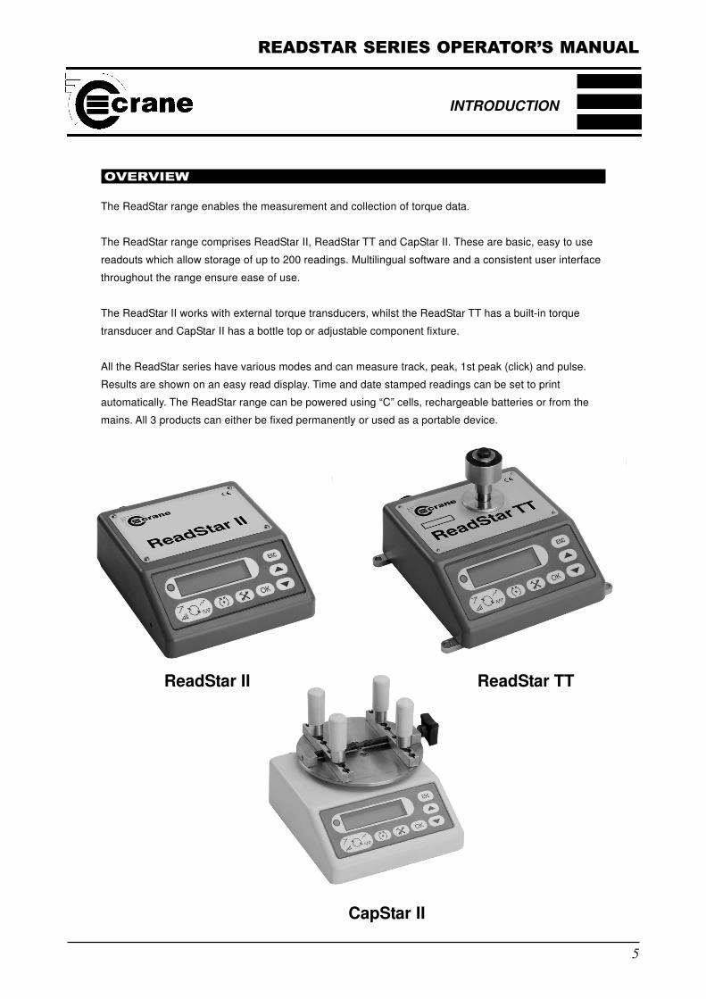
The ReadStar range enables the measurement and collection of torque data.
The ReadStar range comprises ReadStar II, ReadStar TT and CapStar II. These are basic, easy to use
readouts which allow storage of up to 200 readings. Multilingual software and a consistent user interface
throughout the range ensure ease of use.
The ReadStar II works with external torque transducers, whilst the ReadStar TT has a built-in torque
transducer and CapStar II has a bottle top or adjustable component fixture.
All the ReadStar series have various modes and can measure track, peak, 1st peak (click) and pulse.
Results are shown on an easy read display. Time and date stamped readings can be set to print
automatically. The ReadStar range can be powered using “C” cells, rechargeable batteries or from the
mains. All 3 products can either be fixed permanently or used as a portable device.
INTRODUCTION
CapStar II
ReadStar II ReadStar TT
READSTAR SERIES OPERATOR’S MANUAL
6
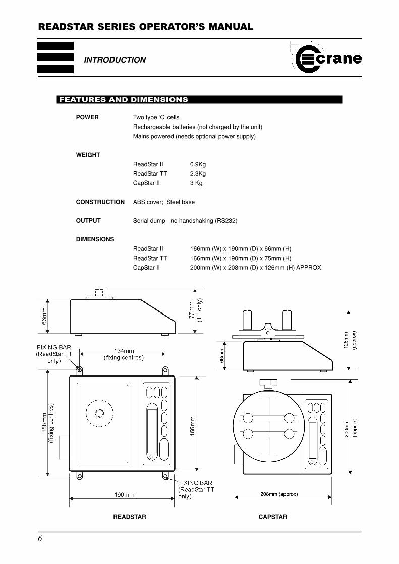
FEATURES AND DIMENSIONS
POWER Two type ‘C’ cells
Rechargeable batteries (not charged by the unit)
Mains powered (needs optional power supply)
WEIGHT
ReadStar II 0.9Kg
ReadStar TT 2.3Kg
CapStar II 3 Kg
CONSTRUCTION ABS cover; Steel base
OUTPUT Serial dump - no handshaking (RS232)
DIMENSIONS
ReadStar II 166mm (W) x 190mm (D) x 66mm (H)
ReadStar TT 166mm (W) x 190mm (D) x 75mm (H)
CapStar II 200mm (W) x 208mm (D) x 126mm (H) APPROX.
INTRODUCTION
READSTAR CAPSTAR
READSTAR SERIES OPERATOR’S MANUAL
7
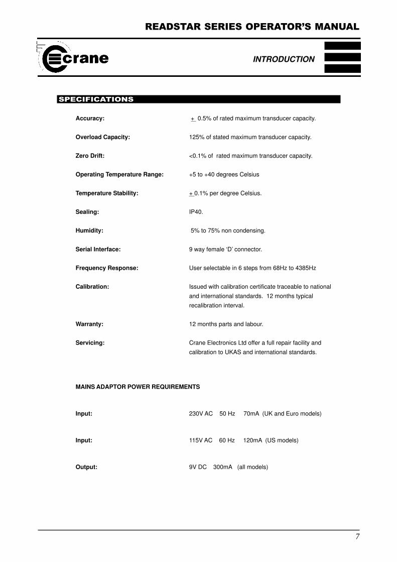
SPECIFICATIONS
Accuracy: + 0.5% of rated maximum transducer capacity.
Overload Capacity: 125% of stated maximum transducer capacity.
Zero Drift: <0.1% of rated maximum transducer capacity.
Operating Temperature Range: +5 to +40 degrees Celsius
Temperature Stability: + 0.1% per degree Celsius.
Sealing: IP40.
Humidity: 5% to 75% non condensing.
Serial Interface: 9 way female ‘D’ connector.
Frequency Response: User selectable in 6 steps from 68Hz to 4385Hz
Calibration: Issued with calibration certificate traceable to national
and international standards. 12 months typical
recalibration interval.
Warranty: 12 months parts and labour.
Servicing: Crane Electronics Ltd offer a full repair facility and
calibration to UKAS and international standards.
MAINS ADAPTOR POWER REQUIREMENTS
Input: 230V AC 50 Hz 70mA (UK and Euro models)
Input: 115V AC 60 Hz 120mA (US models)
Output: 9V DC 300mA (all models)
INTRODUCTION
READSTAR SERIES OPERATOR’S MANUAL
8
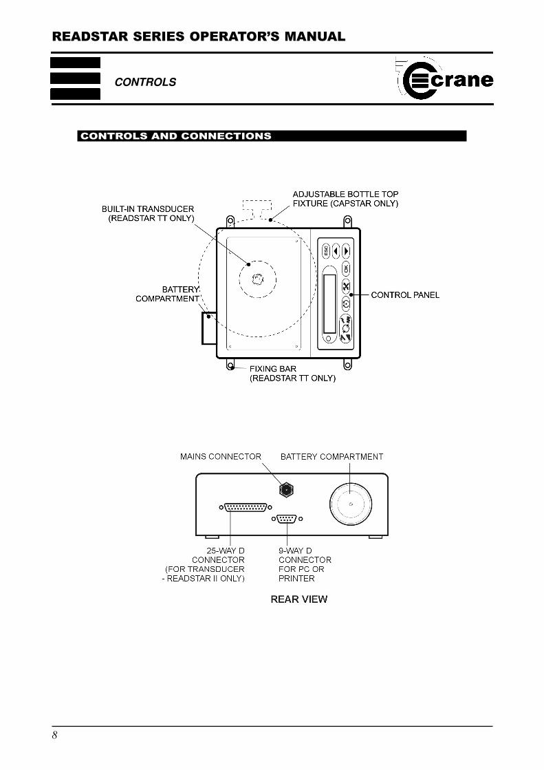
CONTROLS AND CONNECTIONS
CONTROLS
READSTAR SERIES OPERATOR’S MANUAL
9
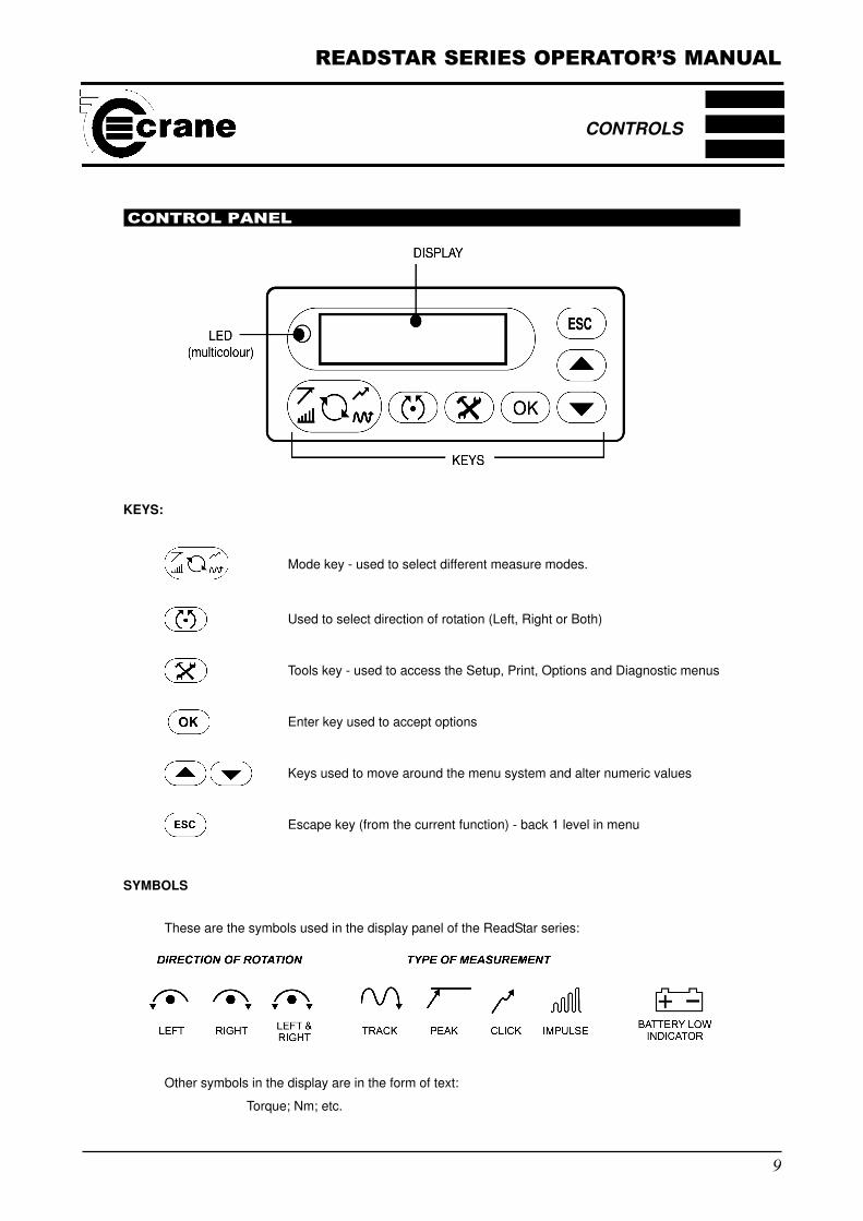
CONTROL PANEL
KEYS:
Mode key - used to select different measure modes.
Used to select direction of rotation (Left, Right or Both)
Tools key - used to access the Setup, Print, Options and Diagnostic menus
Enter key used to accept options
Keys used to move around the menu system and alter numeric values
Escape key (from the current function) - back 1 level in menu
SYMBOLS
These are the symbols used in the display panel of the ReadStar series:
CONTROLS
Other symbols in the display are in the form of text:
Torque; Nm; etc.
READSTAR SERIES OPERATOR’S MANUAL
10
BATTERY LOW INDICATOR
When the batteries are getting low on charge, the battery indicator symbol will show in the bottom
right hand corner of the screen. This indicates to the user the batteries are in need of replacement
or recharging externally if rechargeable batteries are being used. If the batteries are low at switch
on, the display will also show “BATT LOW” in addition to the warning symbol.
When the battery symbol stars to flash, the batteries are almost completely exhausted and auto
shut down is imminent.
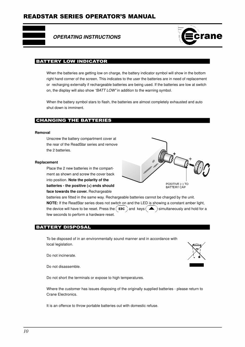
CHANGING THE BATTERIES
Removal
Unscrew the battery compartment cover at
the rear of the ReadStar series and remove
the 2 batteries.
Replacement
Place the 2 new batteries in the compart-
ment as shown and screw the cover back
into position. Note the polarity of the
batteries - the positive (+) ends should
face towards the cover. Rechargeable
batteries are fitted in the same way. Rechargeable batteries cannot be charged by the unit.
NOTE: If the ReadStar series does not switch on and the LED is showing a constant amber light,
the device will have to be reset. Press the and keys simultaneously and hold for a
few seconds to perform a hardware reset.
BATTERY DISPOSAL
To be disposed of in an environmentally sound manner and in accordance with
local legislation.
Do not incinerate.
Do not disassemble.
Do not short the terminals or expose to high temperatures.
Where the customer has issues disposing of the originally supplied batteries - please return to
Crane Electronics.
It is an offence to throw portable batteries out with domestic refuse.
OPERATING INSTRUCTIONS
READSTAR SERIES OPERATOR’S MANUAL
11
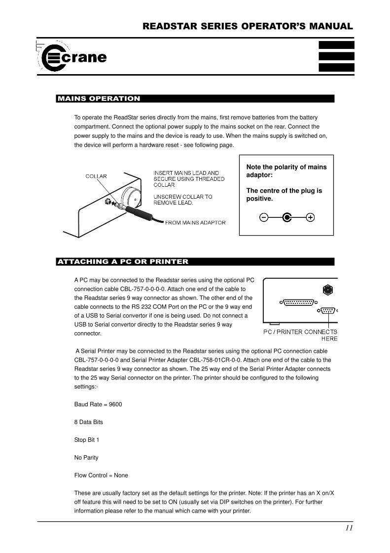
Note the polarity of mainsadaptor:
The centre of the plug ispositive.
MAINS OPERATION
To operate the ReadStar series directly from the mains, first remove batteries from the battery
compartment. Connect the optional power supply to the mains socket on the rear. Connect the
power supply to the mains and the device is ready to use. When the mains supply is switched on,
the device will perform a hardware reset - see following page.
ATTACHING A PC OR PRINTER
A PC may be connected to the Readstar series using the optional PC
connection cable CBL-757-0-0-0-0. Attach one end of the cable to
the Readstar series 9 way connector as shown. The other end of the
cable connects to the RS 232 COM Port on the PC or the 9 way end
of a USB to Serial convertor if one is being used. Do not connect a
USB to Serial convertor directly to the Readstar series 9 way
connector.
A Serial Printer may be connected to the Readstar series using the optional PC connection cable
CBL-757-0-0-0-0 and Serial Printer Adapter CBL-758-01CR-0-0. Attach one end of the cable to the
Readstar series 9 way connector as shown. The 25 way end of the Serial Printer Adapter connects
to the 25 way Serial connector on the printer. The printer should be configured to the following
settings:-
Baud Rate = 9600
8 Data Bits
Stop Bit 1
No Parity
Flow Control = None
These are usually factory set as the default settings for the printer. Note: If the printer has an X on/X
off feature this will need to be set to ON (usually set via DIP switches on the printer). For further
information please refer to the manual which came with your printer.
READSTAR SERIES OPERATOR’S MANUAL
12
OPERATING INSTRUCTIONS
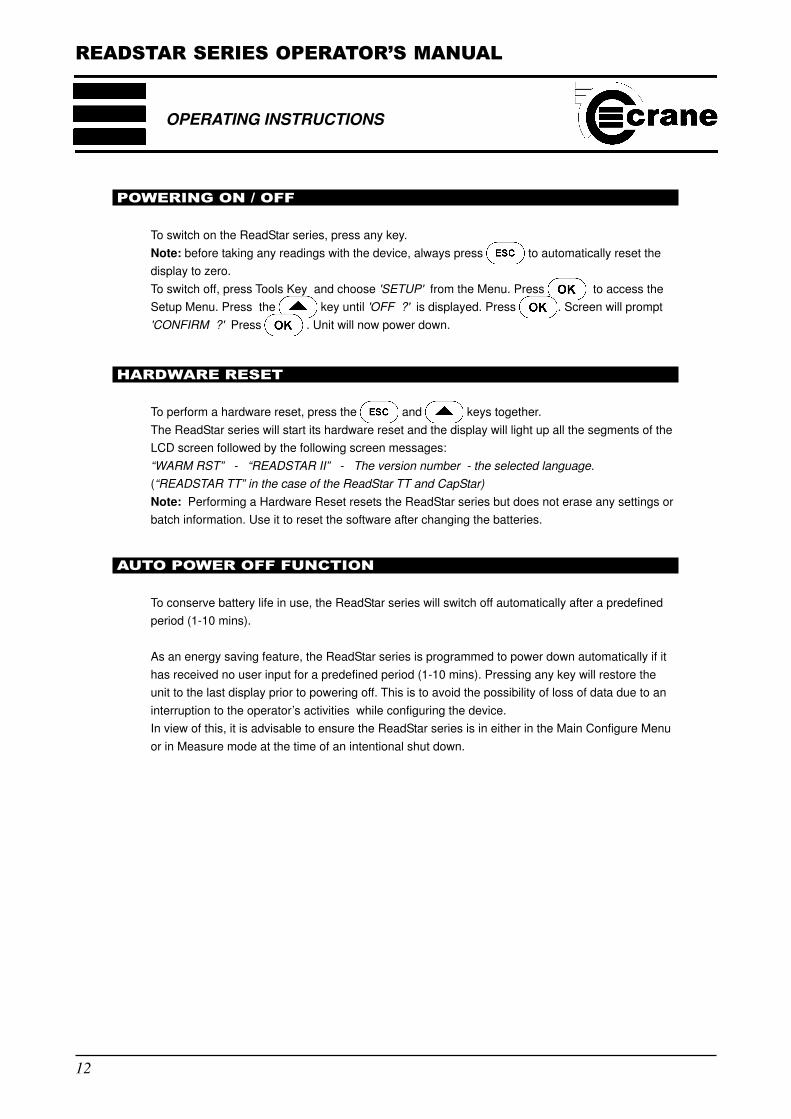
POWERING ON / OFF
To switch on the ReadStar series, press any key.
Note: before taking any readings with the device, always press to automatically reset the
display to zero.
To switch off, press Tools Key and choose 'SETUP' from the Menu. Press to access the
Setup Menu. Press the key until 'OFF ?' is displayed. Press . Screen will prompt
'CONFIRM ?' Press . Unit will now power down.
HARDWARE RESET
To perform a hardware reset, press the and keys together.
The ReadStar series will start its hardware reset and the display will light up all the segments of the
LCD screen followed by the following screen messages:
“WARM RST” - “READSTAR II” - The version number - the selected language.
(“READSTAR TT” in the case of the ReadStar TT and CapStar)
Note: Performing a Hardware Reset resets the ReadStar series but does not erase any settings or
batch information. Use it to reset the software after changing the batteries.
AUTO POWER OFF FUNCTION
To conserve battery life in use, the ReadStar series will switch off automatically after a predefined
period (1-10 mins).
As an energy saving feature, the ReadStar series is programmed to power down automatically if it
has received no user input for a predefined period (1-10 mins). Pressing any key will restore the
unit to the last display prior to powering off. This is to avoid the possibility of loss of data due to an
interruption to the operator’s activities while configuring the device.
In view of this, it is advisable to ensure the ReadStar series is in either in the Main Configure Menu
or in Measure mode at the time of an intentional shut down.
READSTAR SERIES OPERATOR’S MANUAL
13
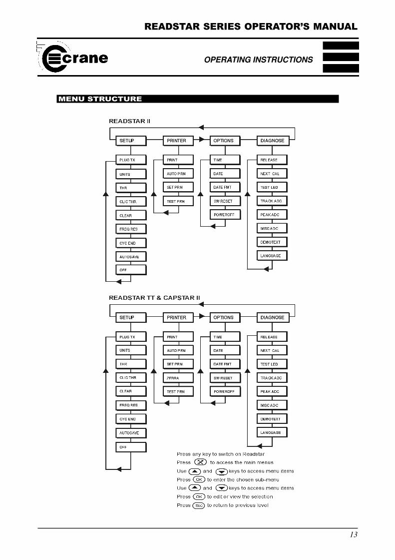
MENU STRUCTURE
OPERATING INSTRUCTIONS
READSTAR SERIES OPERATOR’S MANUAL
14
OPERATING INSTRUCTIONS
BASIC OPERATING PRINCIPLES
The operation of the ReadStar range is basically the same for all 3 units. The only difference is that
ReadStar II requires an external transducer to be attached in order to apply torque, while the
ReadStar TT has a built-in transducer. CapStar II has an adjustable bottle top/component fixture.
The method of operation for both units is based around a simple menu structure for ease of use.
At switch on, the units are in Measure mode, ready to accept torque input.
MEASURE MODE
This is the mode in which the operator applies tightening force to a joint and measures the torque.
Parameters that can be set directly from the Measure Mode are:
Type of Measurement - Peak, Click Dip, Impulse or Track
Direction of Rotation
Press the key repeatedly to toggle between the following options:
Peak Mode
Click Dip Mode
Impulse Mode
Track Mode
Use the Key to toggle between the directions of rotation available (Left, Right or Both)
The following menus are available to change various parameters etc. by pressing the key
on the ReadStar/CapStar and using the and arrow keys to scroll to the required
menu and press .
SET UP MENU (see page 21)
This menu allows the setup of various parameters to be set or viewed. These are; UNITS (Units of
Measurement), THR (Threshold Setting - view only), POWEROFF (see page 10), AUTOSAVE
(Readings automatically added to batch file) and CLEAR (Clear the stored readings).
PRINTER MENU (See page 22)
This menu controls the printer functions - available if a suitable printer is connected using the
optional printer cable. See page 12. The options include printing the stored data, testing the printer,
automatic printing on or off, and setting the printer configuration.
READSTAR SERIES OPERATOR’S MANUAL
15
OPTIONS MENU (See page 23)
The options menu allows the user to set the Time and Date of the unit plus the Date Format. It also
allows the user to change the Power Off settings and to perform a software reset.
DIAGNOSTICS MENU (see page 24)
This menu allows various diagnostics data to be viewed. This includes the product software release
version, the working span of the ReadStar series, the date the next calibration is due, testing the
operation of the LEDs, track A-D converter values, miscellaneous A-D converter values, and a
demonstration text message.
USING THE MENU SYSTEM
Viewing or changing any of the parameters within the menu structure is basically the same.
First, select the tools menu by pressing .
Next use the and arrow keys to scroll to the sub menu containing the menu item to
be viewed or amended.
Press to select the item.
The current item setting will be displayed. If it can be amended by the user, use the and
arrow keys to scroll through the available options and press to select.
If the item requires a numerical input (ie Threshold or Time), the figure will be displayed and the first
field to be edited will be flashing. Use the and arrow keys to increment or
decrement the number and press to select. The next field will now be flashing. Repeat the
process until all the fields have been amended.
In all of these operations, the following rules apply -
and arrow keys to scroll or to increment/decrement numeric values
to select
to escape (back up the menu system 1 level)
OPERATING INSTRUCTIONS
READSTAR SERIES OPERATOR’S MANUAL
16
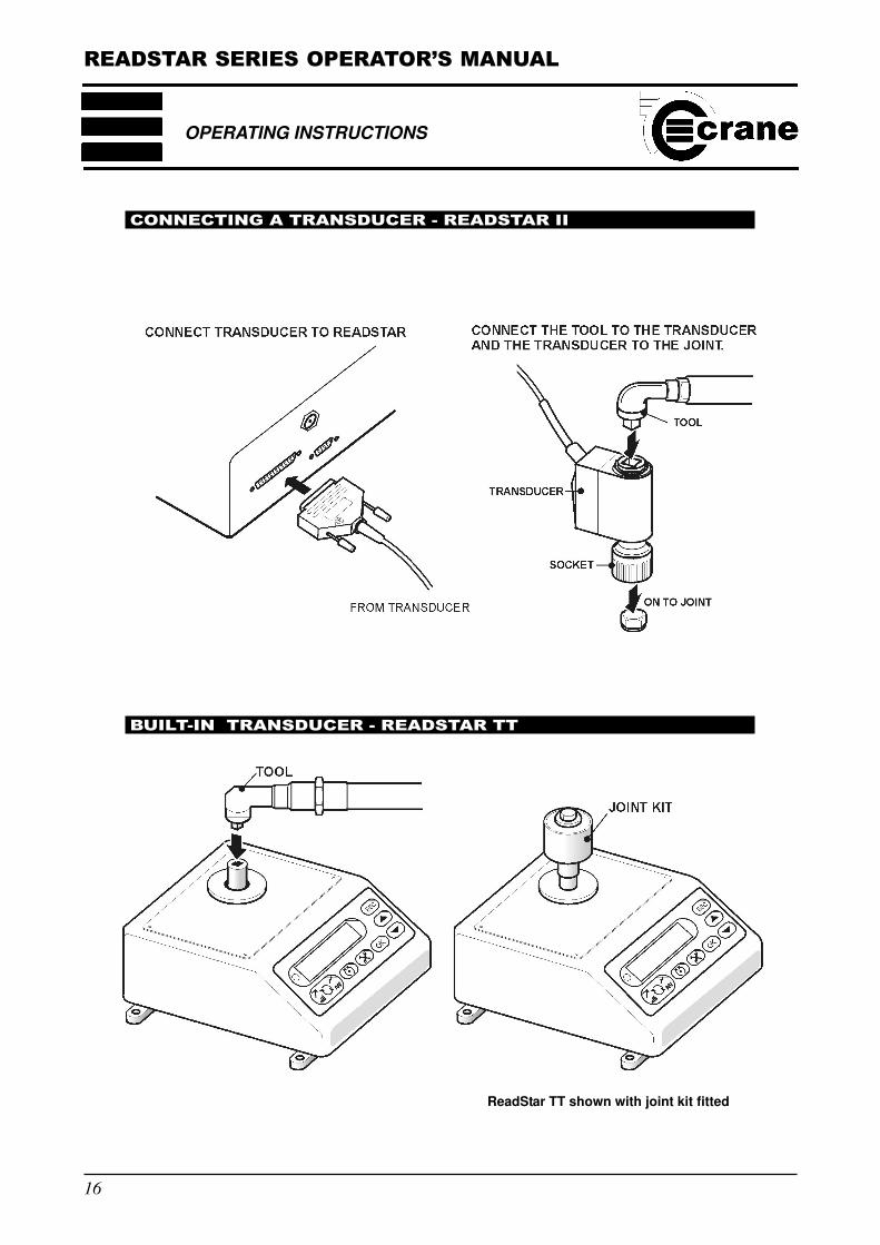
CONNECTING A TRANSDUCER - READSTAR II
BUILT-IN TRANSDUCER - READSTAR TT
ReadStar TT shown with joint kit fitted
OPERATING INSTRUCTIONS
READSTAR SERIES OPERATOR’S MANUAL
17
OPERATING INSTRUCTIONS
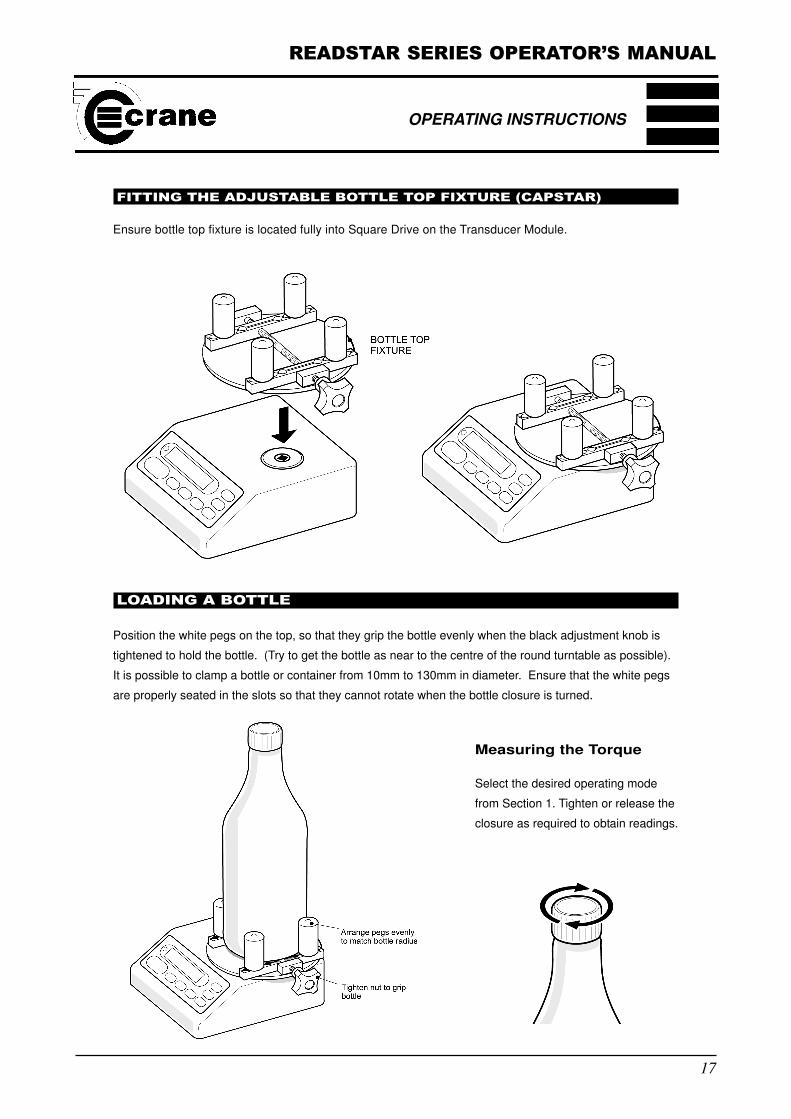
FITTING THE ADJUSTABLE BOTTLE TOP FIXTURE (CAPSTAR)
Ensure bottle top fixture is located fully into Square Drive on the Transducer Module.
LOADING A BOTTLE
Position the white pegs on the top, so that they grip the bottle evenly when the black adjustment knob is
tightened to hold the bottle. (Try to get the bottle as near to the centre of the round turntable as possible).
It is possible to clamp a bottle or container from 10mm to 130mm in diameter. Ensure that the white pegs
are properly seated in the slots so that they cannot rotate when the bottle closure is turned.
MEASURING THE
Measuring the Torque
Select the desired operating mode
from Section 1. Tighten or release the
closure as required to obtain readings.
READSTAR SERIES OPERATOR’S MANUAL
18
OPERATING INSTRUCTIONS
MEASURE MODE (HOW TO TAKE A TORQUE READING)
Switch on the ReadStar series - press any key.
Press to reset the display to zero.
For the ReadStar TT, torque should be applied via a suitable tool to the built-in transducer -
see page 16.
For the ReadStar II, the unit must be connected to a suitable transducer before the torque
can be applied. See page 16.
For the CapStar II, the bottle top fixture must be fitted - see page 17.
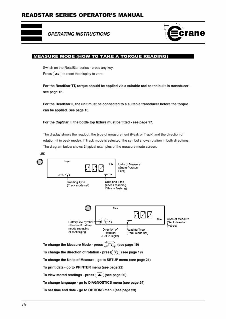
The display shows the readout, the type of measurement (Peak or Track) and the direction of
rotation (if in peak mode). If Track mode is selected, the symbol shows rotation in both directions.
The diagram below shows 2 typical examples of the measure mode screen.
To change the Measure Mode - press (see page 19)
To change the direction of rotation - press (see page 19)
To change the Units of Measure - go to SETUP menu (see page 21)
To print data - go to PRINTER menu (see page 22)
To view stored readings - press (see page 20)
To change language - go to DIAGNOSTICS menu (see page 24)
To set time and date - go to OPTIONS menu (see page 23)
READSTAR SERIES OPERATOR’S MANUAL
19
PEAK MODE SELECTED
If Peak Mode selected, applying torque in the direction selected will cause the peak reading to be
displayed on the screen.
TRACK MODE SELECTED
If Track mode is selected, applying torque in either direction will cause the amount of torque being
applied to be continuously displayed.
CLICK DIP MODE SELECTED
If Click Dip mode is selected, applying torque with a click wrench will cause the click dip reading to
be displayed on the screen.
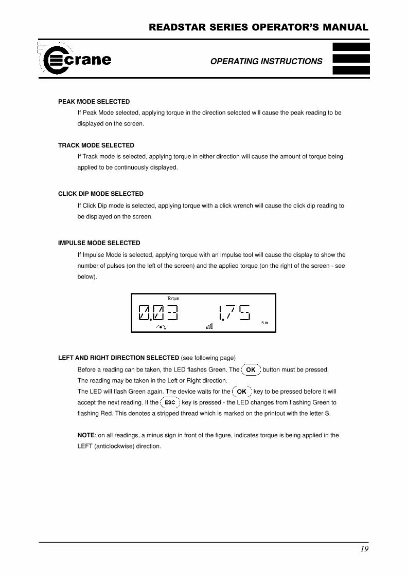
IMPULSE MODE SELECTED
If Impulse Mode is selected, applying torque with an impulse tool will cause the display to show the
number of pulses (on the left of the screen) and the applied torque (on the right of the screen - see
below).
LEFT AND RIGHT DIRECTION SELECTED (see following page)
Before a reading can be taken, the LED flashes Green. The button must be pressed.
The reading may be taken in the Left or Right direction.
The LED will flash Green again. The device waits for the key to be pressed before it will
accept the next reading. If the key is pressed - the LED changes from flashing Green to
flashing Red. This denotes a stripped thread which is marked on the printout with the letter S.
NOTE: on all readings, a minus sign in front of the figure, indicates torque is being applied in the
LEFT (anticlockwise) direction.
OPERATING INSTRUCTIONS
READSTAR SERIES OPERATOR’S MANUAL
20
OPERATING INSTRUCTIONS
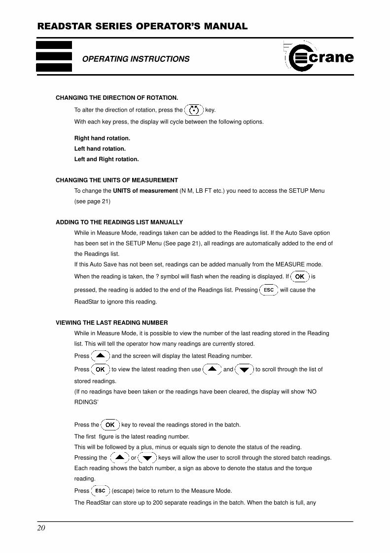
CHANGING THE DIRECTION OF ROTATION.
To alter the direction of rotation, press the key.
With each key press, the display will cycle between the following options.
Right hand rotation.
Left hand rotation.
Left and Right rotation.
CHANGING THE UNITS OF MEASUREMENT
To change the UNITS of measurement (N M, LB FT etc.) you need to access the SETUP Menu
(see page 21)
ADDING TO THE READINGS LIST MANUALLY
While in Measure Mode, readings taken can be added to the Readings list. If the Auto Save option
has been set in the SETUP Menu (See page 21), all readings are automatically added to the end of
the Readings list.
If this Auto Save has not been set, readings can be added manually from the MEASURE mode.
When the reading is taken, the ? symbol will flash when the reading is displayed. If is
pressed, the reading is added to the end of the Readings list. Pressing will cause the
ReadStar to ignore this reading.
VIEWING THE LAST READING NUMBER
While in Measure Mode, it is possible to view the number of the last reading stored in the Reading
list. This will tell the operator how many readings are currently stored.
Press and the screen will display the latest Reading number.
Press to view the latest reading then use and to scroll through the list of
stored readings.
(If no readings have been taken or the readings have been cleared, the display will show ‘NO
RDINGS’
Press the key to reveal the readings stored in the batch.
The first figure is the latest reading number.
This will be followed by a plus, minus or equals sign to denote the status of the reading.
Pressing the or keys will allow the user to scroll through the stored batch readings.
Each reading shows the batch number, a sign as above to denote the status and the torque
reading.
Press (escape) twice to return to the Measure Mode.
The ReadStar can store up to 200 separate readings in the batch. When the batch is full, any
READSTAR SERIES OPERATOR’S MANUAL
21
subsequent readings will wrap around and will begin overwriting the existing readings, starting with
reading 1. To clear the batch, use the CLEAR function in the SETUP Menu - see page 21.
DELETING THE LAST READING NUMBER
Pressing when in Measure Mode will delete the latest reading to be stored in the Reading
list. The LED will glow RED to indicate deletion has taken place. ’CLEAR’ will be shown on the
screen for one second.
NOTE: Only 1 reading may be deleted until another reading has been taken.
SETUP MENU
The following options are available in the SETUP Menu:
PLUG TX (ReadStar II only)
Identifies the transducer attached to the ReadStar II
UNITS
The currently selected Units Of Measurement will be displayed (e.g. NM).
Units available (depending on the span of the ReadStar) are:
N M, KGFCM, KGFM, OZ IN, LB IN, or LB FT,
THR
Threshold - torque level at which to start measurement
CLIC THR
Click threshold - the amount of drop in torque seen when a mechanical wrench clicks. Value set is
dependent on the type of wrench used - usually set to quite a low value.
AUTOSAVE
ON = automatically stores after taking reading
OFF = User must press to store or to disregard reading
If the auto save function is set to OFF, readings can be added manually to the batch list. See
MEASURE mode, page 18.
CLEAR
Deletes all stored readings
FREQ RES
Displays the frequency response
CYC END
Displays the cycle end time
OPERATING INSTRUCTIONS
READSTAR SERIES OPERATOR’S MANUAL
22
OPERATING INSTRUCTIONS
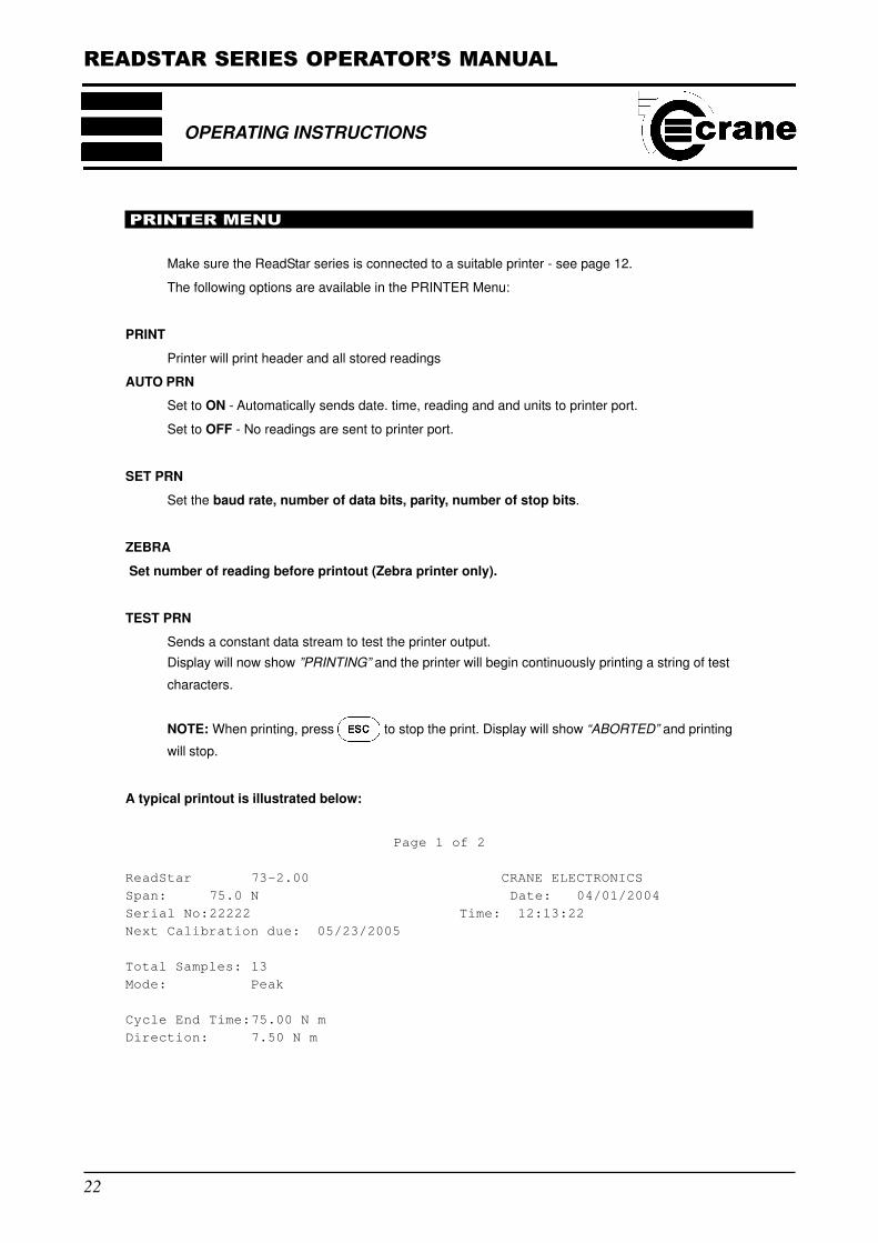
PRINTER MENU
Make sure the ReadStar series is connected to a suitable printer - see page 12.
The following options are available in the PRINTER Menu:
Printer will print header and all stored readings
AUTO PRN
Set to ON - Automatically sends date. time, reading and and units to printer port.
Set to OFF - No readings are sent to printer port.
SET PRN
Set the baud rate, number of data bits, parity, number of stop bits.
ZEBRA
Set number of reading before printout (Zebra printer only).
TEST PRN
Sends a constant data stream to test the printer output.
Display will now show ”PRINTING” and the printer will begin continuously printing a string of test
characters.
NOTE: When printing, press to stop the print. Display will show “ABORTED” and printing
will stop.
A typical printout is illustrated below:
Page 1 of 2
ReadStar 73-2.00 CRANE ELECTRONICS
Span: 75.0 N Date: 04/01/2004
Serial No:22222 Time: 12:13:22
Next Calibration due: 05/23/2005
Total Samples: 13
Mode: Peak
Cycle End Time:75.00 N m
Direction: 7.50 N m
READSTAR SERIES OPERATOR’S MANUAL
23
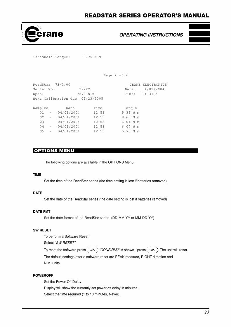
Threshold Torque: 3.75 N m
Page 2 of 2
ReadStar 73-2.00 CRANE ELECTRONICS
Serial No: 22222 Date: 04/01/2004
Span: 75.0 N m Time: 12:13:24
Next Calibration due: 05/23/2005
Samples Date Time Torque
01 - 04/01/2004 12:53 5.38 N m
02 - 04/01/2004 12.53 8.60 N m
03 - 04/01/2004 12:53 6.01 N m
04 - 04/01/2004 12:53 6.07 N m
05 - 04/01/2004 12:53 5.70 N m
OPTIONS MENU
The following options are available in the OPTIONS Menu:
TIME
Set the time of the ReadStar series (the time setting is lost if batteries removed)
DATE
Set the date of the ReadStar series (the date setting is lost if batteries removed)
DATE FMT
Set the date format of the ReadStar series (DD-MM-YY or MM-DD-YY)
SW RESET
To perform a Software Reset:
Select “SW RESET”
To reset the software press “CONFIRM?” is shown - press . The unit will reset.
The default settings after a software reset are PEAK measure, RIGHT direction and
N M units.
POWEROFF
Set the Power Off Delay
Display will show the currently set power off delay in minutes.
Select the time required (1 to 10 minutes, Never).
OPERATING INSTRUCTIONS
READSTAR SERIES OPERATOR’S MANUAL
24
OPERATING INSTRUCTIONS
DIAGNOSTIC MENU
This menu allows various diagnostics data to be viewed.
Menu options are:
RELEASE
View the Software Release Number:
NEXT CAL
View the next calibration due date
TEST LED
Test operation of LEDs:
The LED will cycle 3 times through its colours (RED, GREEN and AMBER) with a text
confirmation. The unit automatically returns to the DIAGNOSTIC MENU.
TRACKADC
View the ADC value for track mode
The 4 digits indicate an averaged value of the Analogue to Digital converter output.
Application of right hand torque will cause the value to increase.
Application of left hand torque will cause the value to decrease.
NOTE: With no torque applied the values displayed will be 2048 ± 50
PEAK ADC
View ADC value for peak mode.
MISC ADC
The display will scroll through the remaining internal A/D converter numbers and display their
current output value. The normal values for these outputs are given below.
A/D No Value
7 128 (±6)
8 128 (±6)
9 255 (±5)
10 255 (±5)
11 42-90
DEMOTEXT
Displays LCD test routine - a scrolling message appears
SPAN - ReadStar TT and CapStar II only
Displays the torque span of the built-in transducer
LANGUAGE
User can change the language of the ReadStar (English, Spanish, German, Swedish, French,
Italian, Czech, Portugese)
READSTAR SERIES OPERATOR’S MANUAL
25
TROUBLESHOOTING GUIDE
The following guide gives some of the possible problems which could be encountered with the
ReadStar series, the possible causes, and the suggested remedial action.
Fault
LCD panel does not come on at power up.
Possible Cause
A Batteries not fitted correctly or not secured.
B Insufficient charge if using Ni-cad rechargeable batteries.
C Mains adaptor not connected correctly.
Action
A Ensure the batteries are seated properly and the polarity is correct. Ensure
the battery compartment cover is screwed down correctly. See page 10.
B Recharge batteries external to unit. See page 10
C Check connection of the mains adaptor to the ReadStar series and check the
power supply is connected to the mains and switched on. If necessary, try the
ReadStar series with batteries to check if mains adaptor has a fault.
Try the mains adaptor with all batteries removed from the device.
OPERATING INSTRUCTIONS
READSTAR SERIES OPERATOR’S MANUAL
26
OPERATING INSTRUCTIONS
GLOSSARY OF TERMS
Angle Wrenches (also known as nutrunners)
Continuously driven tools which rely on torque reaction to cut off the air supply.
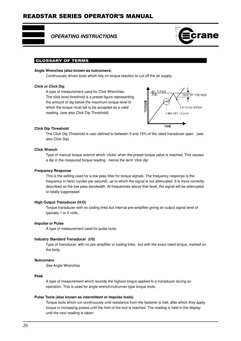
Click or Click Dip
A type of measurement used for Click Wrenches.
The click level threshold is a preset figure representing
the amount of dip below the maximum torque level to
which the torque must fall to be accepted as a valid
reading. (see also Click Dip Threshold)
Click Dip Threshold
The Click Dip Threshold is user defined to between 5 and 15% of the rated transducer span. (see
also Click Dip)
Click Wrench
Type of manual torque wrench which ‘clicks’ when the preset torque value is reached. This causes
a dip in the measured torque reading - hence the term ‘click dip’.
Frequency Response
This is the setting used for a low pass filter for torque signals. The frequency response is the
frequency in hertz (cycles per second), up to which the signal is not attenuated. It is more correctly
described as the low pass bandwidth. At frequencies above that level, the signal will be attenuated
or totally suppressed
High Output Transducer (H/O)
Torque transducer with no coding links but internal pre-amplifier giving an output signal level of
typically 1 or 2 volts.
Impulse or Pulse
A type of measurement used for pulse tools.
Industry Standard Transducer (I/S)
Type of transducer, with no pre-amplifier or coding links, but with the exact rated torque, marked on
the body.
Nutrunners
See Angle Wrenches
Peak
A type of measurement which records the highest torque applied to a transducer during an
operation. This is used for angle wrench/nutrunner type torque tools.
Pulse Tools (also known as intermittent or impulse tools)
Torque tools which run continuously until resistance from the fastener is met, after which they apply
torque in increasing pulses until the limit of the tool is reached. The reading is held in the display
until the next reading is taken.
READSTAR SERIES OPERATOR’S MANUAL
27
Sample
Individual torque reading.
Span
The Span is the effective operating range of a transducer. This is the range between zero and the
maximum design limit of the transducer.
Threshold Torque Value
The level of torque which a signal must rise above and then fall below to be considered a valid
torque cycle. In the ReadStar series, this is set at 5% of the rated span of the transducer.
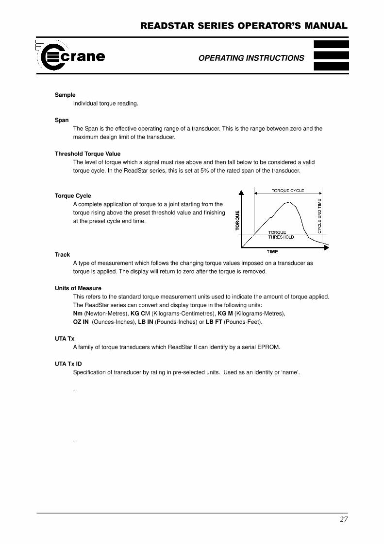
Torque Cycle
A complete application of torque to a joint starting from the
torque rising above the preset threshold value and finishing
at the preset cycle end time.
Track
A type of measurement which follows the changing torque values imposed on a transducer as
torque is applied. The display will return to zero after the torque is removed.
Units of Measure
This refers to the standard torque measurement units used to indicate the amount of torque applied.
The ReadStar series can convert and display torque in the following units:
Nm (Newton-Metres), KG CM (Kilograms-Centimetres), KG M (Kilograms-Metres),
OZ IN (Ounces-Inches), LB IN (Pounds-Inches) or LB FT (Pounds-Feet).
UTA Tx
A family of torque transducers which ReadStar II can identify by a serial EPROM.
UTA Tx ID
Specification of transducer by rating in pre-selected units. Used as an identity or ‘name’.
.
.
OPERATING INSTRUCTIONS