Embed Size (px)
Citation preview

3M-Matic, AccuGlide, and Scotch areTrademarks of 3M, St. Paul, MN 55144-1000
Printed in U.S.A.
© 3M 2005 44-0009-2040-3 (A)
Important SafetyInformation
Spare Parts
BEFORE INSTALLING OR
OPERATING THIS
EQUIPMENT
Read, understand, and follow all
safety and operating instructions.
It is recommended you
immediately order the spare
parts listed in the "Spare
Parts/Service Information"
section. These parts are
expected to wear through
normal use, and should be
kept on hand to minimize
production delays.
3M Industrial Adhesives and Tapes3M Center, Building 220-5E-06St. Paul, MN 55144-1000
Serial No. For reference, record machine serial number here.
™
Instructions and Parts List
800af-s Type 10500
Stainless SteelAdjustableCase Sealer
with
AccuGlide SSTTaping Heads
3M-Matic™


Replacement Parts and Service Information
To Our Customers:To Our Customers:To Our Customers:To Our Customers:To Our Customers:This is the 3M-Matic™/AccuGlide™/ScotchThis is the 3M-Matic™/AccuGlide™/ScotchThis is the 3M-Matic™/AccuGlide™/ScotchThis is the 3M-Matic™/AccuGlide™/ScotchThis is the 3M-Matic™/AccuGlide™/Scotch®®®®® equipment you ordered. It has equipment you ordered. It has equipment you ordered. It has equipment you ordered. It has equipment you ordered. It hasbeen set up and tested in the factory with Scotchbeen set up and tested in the factory with Scotchbeen set up and tested in the factory with Scotchbeen set up and tested in the factory with Scotchbeen set up and tested in the factory with Scotch®®®®® tapes. If technical tapes. If technical tapes. If technical tapes. If technical tapes. If technicalassistance or replacement parts are needed, call or fax the appropriateassistance or replacement parts are needed, call or fax the appropriateassistance or replacement parts are needed, call or fax the appropriateassistance or replacement parts are needed, call or fax the appropriateassistance or replacement parts are needed, call or fax the appropriatenumber listed below.number listed below.number listed below.number listed below.number listed below.
Included with each machine is an Instructions and Parts List manual.Included with each machine is an Instructions and Parts List manual.Included with each machine is an Instructions and Parts List manual.Included with each machine is an Instructions and Parts List manual.Included with each machine is an Instructions and Parts List manual.
Replacement Parts and Additional ManualsReplacement Parts and Additional ManualsReplacement Parts and Additional ManualsReplacement Parts and Additional ManualsReplacement Parts and Additional Manuals
Order parts by part number, part description and quantity required. Also, when
ordering parts and/or additional manuals, include machine name, number and
type. A parts order form is provided at the back of this manual.
3M/Tape Dispenser Parts3M/Tape Dispenser Parts3M/Tape Dispenser Parts3M/Tape Dispenser Parts3M/Tape Dispenser Parts
241 Venture Drive241 Venture Drive241 Venture Drive241 Venture Drive241 Venture Drive 1-800/344 98831-800/344 98831-800/344 98831-800/344 98831-800/344 9883
Amery, WI 54001-1325Amery, WI 54001-1325Amery, WI 54001-1325Amery, WI 54001-1325Amery, WI 54001-1325 FAX# 715/268 8153FAX# 715/268 8153FAX# 715/268 8153FAX# 715/268 8153FAX# 715/268 8153
Technical Assistance:Technical Assistance:Technical Assistance:Technical Assistance:Technical Assistance:
3M-Matic™ Helpline – 1-800/328 1390. Please provide the customer support
coordinator with the machine number, machine type/model and serial number. If
you have a technical question that does not require an immediate response, you
may Fax it to 651-736-7282.
Minimum billing on parts orders will be $25.00. Replacement part prices available on request.Minimum billing on parts orders will be $25.00. Replacement part prices available on request.Minimum billing on parts orders will be $25.00. Replacement part prices available on request.Minimum billing on parts orders will be $25.00. Replacement part prices available on request.Minimum billing on parts orders will be $25.00. Replacement part prices available on request.
Note: Outside the U.S., contact the local 3M subsidiary for parts ordering information.
$10.00 restocking charge per invoice on returned parts.$10.00 restocking charge per invoice on returned parts.$10.00 restocking charge per invoice on returned parts.$10.00 restocking charge per invoice on returned parts.$10.00 restocking charge per invoice on returned parts.
3M-Matic™, AccuGlide™ and Scotch™ are Trademarks of 3M,St. Paul, MN 55144-1000
Printed in U.S.A.
© 3M 2005 44-0009-1851-4 (F)
3M Industrial Adhesives and Tapes3M Center, Building 220-5E-06St. Paul, MN 55144-1000


Replacement Parts And Service Information
To Our Customers:To Our Customers:To Our Customers:To Our Customers:To Our Customers:This is the 3M-Matic™/AccuGlide™/ScotchThis is the 3M-Matic™/AccuGlide™/ScotchThis is the 3M-Matic™/AccuGlide™/ScotchThis is the 3M-Matic™/AccuGlide™/ScotchThis is the 3M-Matic™/AccuGlide™/Scotch®®®®® equipment you ordered. It has equipment you ordered. It has equipment you ordered. It has equipment you ordered. It has equipment you ordered. It hasbeen set up and tested in the factory with Scotchbeen set up and tested in the factory with Scotchbeen set up and tested in the factory with Scotchbeen set up and tested in the factory with Scotchbeen set up and tested in the factory with Scotch®®®®® tapes. If any problems tapes. If any problems tapes. If any problems tapes. If any problems tapes. If any problemsoccur when operating this equipment and you desire a service call oroccur when operating this equipment and you desire a service call oroccur when operating this equipment and you desire a service call oroccur when operating this equipment and you desire a service call oroccur when operating this equipment and you desire a service call orphone consultation, call, write or fax the appropriate number listed below.phone consultation, call, write or fax the appropriate number listed below.phone consultation, call, write or fax the appropriate number listed below.phone consultation, call, write or fax the appropriate number listed below.phone consultation, call, write or fax the appropriate number listed below.
Included with each machine is an Instructions and Parts List manual.Included with each machine is an Instructions and Parts List manual.Included with each machine is an Instructions and Parts List manual.Included with each machine is an Instructions and Parts List manual.Included with each machine is an Instructions and Parts List manual.
SERVICE, REPLACEMENT PARTS AND ADDITIONAL MANUALSSERVICE, REPLACEMENT PARTS AND ADDITIONAL MANUALSSERVICE, REPLACEMENT PARTS AND ADDITIONAL MANUALSSERVICE, REPLACEMENT PARTS AND ADDITIONAL MANUALSSERVICE, REPLACEMENT PARTS AND ADDITIONAL MANUALS
AVAILABLE DIRECT FROM:AVAILABLE DIRECT FROM:AVAILABLE DIRECT FROM:AVAILABLE DIRECT FROM:AVAILABLE DIRECT FROM:
Order parts by part number, part description and quantity required. Also, when
ordering parts and/or additional manuals, include machine name, number and type.
3M-Matic™, AccuGlide™ and Scotch™ are Trademarks of 3M,St. Paul, MN 55144-1000
Printed in U.S.A.
© 3M 2005 44-0009-1852-2(E)
3M Industrial Adhesives and Tapes3M Center, Building 220-5E-06St. Paul, MN 55144-1000


Instruction ManualInstruction ManualInstruction ManualInstruction ManualInstruction Manual
800af-s Stainless Steel Adjustable Case Sealer800af-s Stainless Steel Adjustable Case Sealer800af-s Stainless Steel Adjustable Case Sealer800af-s Stainless Steel Adjustable Case Sealer800af-s Stainless Steel Adjustable Case SealerType 10500Type 10500Type 10500Type 10500Type 10500
Table of ContentsTable of ContentsTable of ContentsTable of ContentsTable of Contents Page Page Page Page Page
Intended Use ................................................................................................................................... 1
Equipment Warranty and Limited Remedy ..................................................................................... 2
Contents – 800af-s Stainless Steel Adjustable Case Sealer ......................................................... 2
Important Safeguards ..................................................................................................................... 3 - 6
Specifications .................................................................................................................................. 7 - 11
Set-Up Procedure ........................................................................................................................... 12 - 15Receiving and Handling ....................................................................................... 12Machine Set-Up .................................................................................................. 12 - 15Initial Start-Up of Case Sealer ............................................................................. 15
Operation ......................................................................................................................................... 16 - 25Case Sealer Components ................................................................................... 16 - 18Operation "Warnings" ......................................................................................... 19Tape Loading/Threading ...................................................................................... 19Box Size Set-Up ................................................................................................. 20 - 24Box Sealing ........................................................................................................ 24Box Jams ............................................................................................................ 25
Maintenance .................................................................................................................................... 26 - 29Cleaning .............................................................................................................. 26Lubrication .......................................................................................................... 26Drive Belt Replacement/Tension Adjustment ...................................................... 27 - 28Air Line Filter ...................................................................................................... 29Circuit Breaker .................................................................................................... 29Knife Replacement, Taping Heads ...................................................................... 29
Adjustments .................................................................................................................................... 30 - 32Gate Operation ................................................................................................... 30Drive Belt Tension ............................................................................................... 30Taping Head Adjustments ................................................................................... 30Upper Taping Head Leveling ................................................................................ 31Gate Pressure Regulator ..................................................................................... 32Gate Stroke Setting ............................................................................................ 32
i
(Table of Contents continued on next page)
This instruction manual is divided into two sections as follows:This instruction manual is divided into two sections as follows:This instruction manual is divided into two sections as follows:This instruction manual is divided into two sections as follows:This instruction manual is divided into two sections as follows:
Section ISection ISection ISection ISection I Includes all information related to installation, operation and parts for the case sealer.Section IISection IISection IISection IISection II Includes specific information regarding the AccuGlide™ SST 2 Inch Taping Heads.
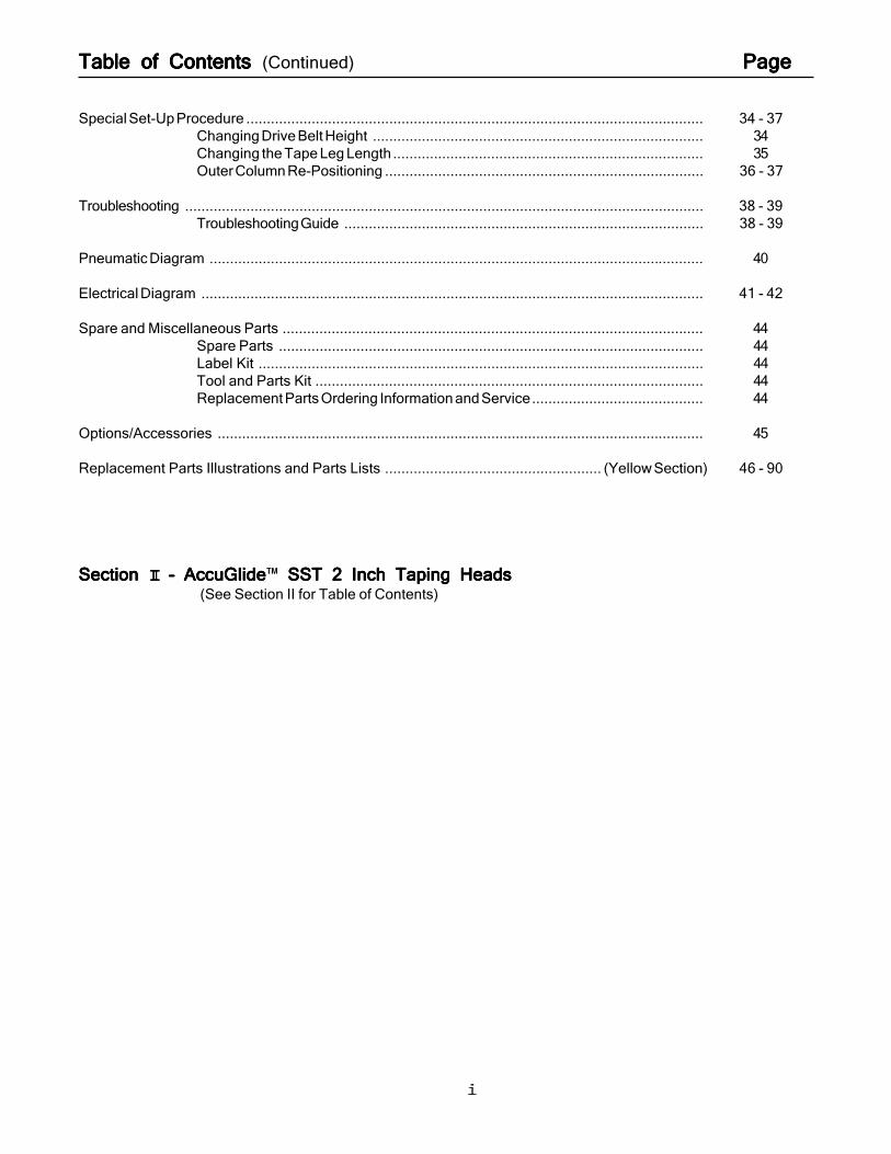
Table of Contents Table of Contents Table of Contents Table of Contents Table of Contents (Continued) PagePagePagePagePage
Special Set-Up Procedure ................................................................................................................ 34 - 37Changing Drive Belt Height ................................................................................. 34Changing the Tape Leg Length ............................................................................ 35Outer Column Re-Positioning .............................................................................. 36 - 37
Troubleshooting ............................................................................................................................... 38 - 39Troubleshooting Guide ........................................................................................ 38 - 39
Pneumatic Diagram ......................................................................................................................... 40
Electrical Diagram ........................................................................................................................... 41 - 42
Spare and Miscellaneous Parts ....................................................................................................... 44Spare Parts ........................................................................................................ 44Label Kit ............................................................................................................. 44Tool and Parts Kit ............................................................................................... 44Replacement Parts Ordering Information and Service.......................................... 44
Options/Accessories ....................................................................................................................... 45
Replacement Parts Illustrations and Parts Lists ..................................................... (Yellow Section) 46 - 90
Section Section Section Section Section II II II II II – AccuGlide– AccuGlide– AccuGlide– AccuGlide– AccuGlide™ SST 2 Inch Taping HeadsSST 2 Inch Taping HeadsSST 2 Inch Taping HeadsSST 2 Inch Taping HeadsSST 2 Inch Taping Heads(See Section II for Table of Contents)
ii
1
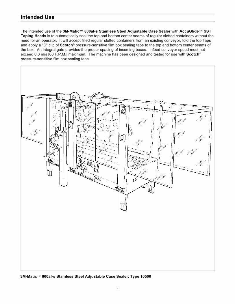
3M-Matic™ 800af-s Stainless Steel Adjustable Case Sealer, Type 10500
Intended Use
The intended use of the 3M-Matic™ 800af-s Stainless Steel Adjustable Case Sealer with AccuGlide™ SSTTaping Heads is to automatically seal the top and bottom center seams of regular slotted containers without theneed for an operator. It will accept filled regular slotted containers from an existing conveyor, fold the top flapsand apply a "C" clip of Scotch® pressure-sensitive film box sealing tape to the top and bottom center seams ofthe box. An integral gate provides the proper spacing of incoming boxes. Infeed conveyor speed must notexceed 0.3 m/s [60 F.P.M.] maximum. The machine has been designed and tested for use with Scotch®
pressure-sensitive film box sealing tape.
2
Contents – 800af-s Stainless Steel Adjustable Case Sealer
(1) 800af-s Stainless Steel Adjustable Case Sealer, Type 10500(1) Tool/Spare Parts Kit(1) Instruction and Parts Manual
ScotchT® , AccuGlideTM, and 3M-MaticTM are Trademarks of 3M, St. Paul, Minnesota 55144-1000
Equipment Warranty and Limited Remedy: THE FOLLOWING WARRANTY IS MADE IN LIEU OF ALLOTHER WARRANTIES, EXPRESS OR IMPLIED, INCLUDING, BUT NOT LIMITED TO, THE IMPLIEDWARRANTY OF MERCHANTABILITY, THE IMPLIED WARRANTY OF FITNESS FOR A PARTICULARPURPOSE AND ANY IMPLIED WARRANTY ARISING OUT OF A COURSE OF DEALING, A CUSTOM ORUSAGE OF TRADE:
3M sells its 3M-Matic™ 800af-s Type 10500 with the following warranties: 1. The drive belts and the taping head knives, springs and rollers will be free from all defects for ninety (90)
days after delivery. 2. All other taping head parts will be free from all defects for three (3) years after delivery. 3. All other parts will be free from all defects for two (2) years after delivery.
If any part is proved to be defective within its warranty period, then the exclusive remedy and 3M’s and seller’ssole obligation shall be, at 3M’s option, to repair or replace the part, provided the defective part is returnedimmediately to 3M’s factory or an authorized service station designated by 3M. A part will be presumed to havebecome defective after its warranty period unless the part is received or 3M is notified of the problem no laterthan five (5) calendar days after the warranty period. If 3M is unable to repair or replace the part within areasonable time, then 3M at its option, will replace the equipment or refund the purchase price. 3M shall haveno obligation to provide or pay for the labor required to install the repaired or replacement part. 3M shall haveno obligation to repair or replace (1) those parts failing due to operator misuse, carelessness, or due to anyaccidental cause other than equipment failure, or (2) parts failing due to non-lubrication, inadequate cleaning,improper operating environment, improper utilities or operator error.
Limitation of Liability: 3M and seller shall not be liable for direct, indirect, special, incidental or consequentialdamages based upon breach of warranty, breach of contract, negligence, strict liability or any other legal theory.
The foregoing Equipment Warranty and Limited Remedy and Limitation of Liability may be changed only by awritten agreement signed by authorized officers of 3M and seller.

3
Important Safeguards
Explanation of Signal Word Consequences
Indicates a potentially hazardoussituation, which, if not avoided,could result in death or seriousinjury and/or property damage.
WARNING:
Indicates a potentially hazardoussituation, which, if not avoided,may result in minor or moderateinjury and/or property damage.
CAUTION:
• To reduce the risk associated withmechanical and electrical hazards:− Read, understand and follow all safety and
operating instructions before operating orservicing the case sealer
− Allow only properly trained and qualifiedpersonnel to operate and/or service thisequipment
− Turn electrical and air supply off anddisconnect before performing anyadjustments, maintenance or servicing themachine or taping heads
• To reduce the risk associated with pinch,entanglement and impact hazards:− Do not leave the machine running while
unattended
− Turn the machine off while not in use
− Never attempt to work on any part of themachine, load tape, or remove jammed boxesfrom the machine while the machine isrunning
− Keep away from moving belts andpneumatically controlled kicker
• To reduce the risk associated withhazadous voltage:
− Position electrical cord away from foot and/orvehicle traffic
WARNING
• To reduce the risk associated with pinchand entanglement hazards:− Keep hands clear of the upper head support
assembly as boxes are transported throughthe machine
− Always feed boxes into the machine bypushing only from the end of the box
− Keep hands, hair, loose clothing, and jewelryaway from moving belts and taping heads
• To reduce the risk associated with pinchhazards:− Keep away from the pneumatically controlled
upper drive assembly and box centeringguides when air and electric supplies are on
CAUTION
• To reduce the risk associated with impacthazards:− Always use appropriate supporting means
when working under the upper drive assembly
− Turn air supply off and be sure flap kicker isdown before servicing
− Never operate this equipment with safetyinterlocks or guarding removed
• To reduce the risk associated with sharpblade hazards:− Keep hands and fingers away from tape cutoff
blades under orange blade guards. Theblades are extremely sharp
• To reduce the risk associated with fire andexplosion hazards:− Do not operate this equipment in potentially
flammable/explosive environments
• To reduce the risk associated with musclestrain:− Use the appropriate rigging and material
handling equipment when lifting orrepositioning this equipment
− Use proper body mechanics when removingor installing taping heads that are moderatelyheavy or may be considered awkward to lift
− Use proper body mechanics when removingor clearing jammed boxes from the machine
WARNING (continued)This safety alert symbol identifiesimportant messages in this manual.
READ AND UNDERSTAND THEM BEFOREINSTALLING OR OPERATING THISEQUIPMENT.

4
Important Safeguards (Continued)
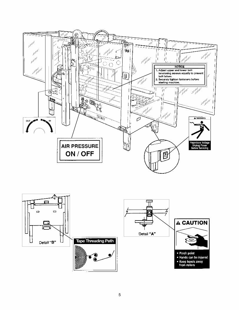
Figure 1-1 – Replacement Labels/3M Part Numbers
Important – In the event the following safety labels are damaged or destroyed, they must be replaced toensure operator safety. Replacement part numbers for individual labels are shown in Figures 1-1, or a label kit,part number 78-8133-9619-5, is available that includes all labels used on the machine.
This safety alert symbol identifiesimportant messages in this manual.
READ AND UNDERSTAND THEM BEFOREINSTALLING OR OPERATING THISEQUIPMENT.
5
6
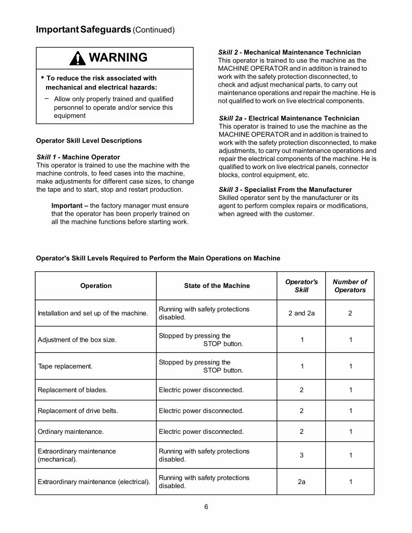
Skill 1 - Machine OperatorThis operator is trained to use the machine with themachine controls, to feed cases into the machine,make adjustments for different case sizes, to changethe tape and to start, stop and restart production.
Important – the factory manager must ensurethat the operator has been properly trained onall the machine functions before starting work.
Important Safeguards (Continued)
Skill 2 - Mechanical Maintenance TechnicianThis operator is trained to use the machine as theMACHINE OPERATOR and in addition is trained towork with the safety protection disconnected, tocheck and adjust mechanical parts, to carry outmaintenance operations and repair the machine. He isnot qualified to work on live electrical components.
Skill 3 - Specialist From the ManufacturerSkilled operator sent by the manufacturer or itsagent to perform complex repairs or modifications,when agreed with the customer.
Skill 2a - Electrical Maintenance TechnicianThis operator is trained to use the machine as theMACHINE OPERATOR and in addition is trained towork with the safety protection disconnected, to makeadjustments, to carry out maintenance operations andrepair the electrical components of the machine. He isqualified to work on live electrical panels, connectorblocks, control equipment, etc.
noitarepO enihcaMehtfoetatS s'rotarepOllikS
forebmuNsrotarepO
.enihcamehtfoputesdnanoitallatsnI snoitcetorpytefashtiwgninnuR.delbasid a2dna2 2
.ezisxobehtfotnemtsujdA ehtgnisserpybdeppotS.nottubPOTSYCNEGREME 1 1
.tnemecalperepaT ehtgnisserpybdeppotS.nottubPOTSYCNEGREME 1 1
.sedalbfotnemecalpeR .detcennocsidrewopcirtcelE 2 1
.stlebevirdfotnemecalpeR .detcennocsidrewopcirtcelE 2 1
.ecnanetniamyranidrO .detcennocsidrewopcirtcelE 2 1
ecnanetniamyranidroartxE.)lacinahcem(
snoitcetorpytefashtiwgninnuR.delbasid 3 1
.)lacirtcele(ecnanetniamyranidroartxE snoitcetorpytefashtiwgninnuR.delbasid a2 1
Operator Skill Level Descriptions
Operator's Skill Levels Required to Perform the Main Operations on Machine
• To reduce the risk associated withmechanical and electrical hazards:− Allow only properly trained and qualified
personnel to operate and/or service thisequipment
WARNING

7
Specifications
(continued)
1. Power Requirements:
Electrical – 115 VAC, 60 Hz, 3.8 Amp (440 watts)
Pneumatic – 6.5 bar gauge pressure [95 PSIG], 2.5 SCFM 75 liter/minute @ 21° C., 1.01 bar maximum at maximum cycle rate. A pressure regulator/filter is included.
The machine is equipped with two 1/6 HP gearmotors and comes with an 2.4 m [8 foot] standard neoprenecovered power cord and a grounded plug. Contact your 3M Representative for power requirements not listedabove.
2. Operating Rate:
Note - Machine is shipped with both cams (A and B) installed. To obtain production rate shownwith dotted line (cam A only), cam B must be removed. See "Adjustments – Gate Operation".

8
IMPORTANT SAFEGUARDIMPORTANT SAFEGUARD
Specifications (Continued)
(continued)
3. Operating Conditions:
Use in a relatively clean environments at 5o to 40o C [40o to 105o F] with clean, dry boxes.
Important – Machine should not be washed down .
4. Tape:
Scotch® pressure-sensitive film box sealing tapes.
5. Tape Width:
36 mm [1-1/2 inch] minimum to 48 mm [2 inch] maximum
6. Tape Roll Diameter:
Up to 405 mm [16 inch] maximum on a 76.2 mm [3 inch] diameter core.(Accommodates all system roll lengths of Scotch® film tapes.)
7. Tape Application Leg Length – Standard:
70 mm ±6 mm [2-3/4 inch ±1/4 inch]
8. Box Board:
Style – regular slotted containers – RSC125 to 275 P.S.I. bursting test, single wall B or C flute.
• To reduce the risk associated with fire andexplosion hazards:− Do not operate this equipment in potentially
flammable/explosive environments
WARNING
9
(continued)
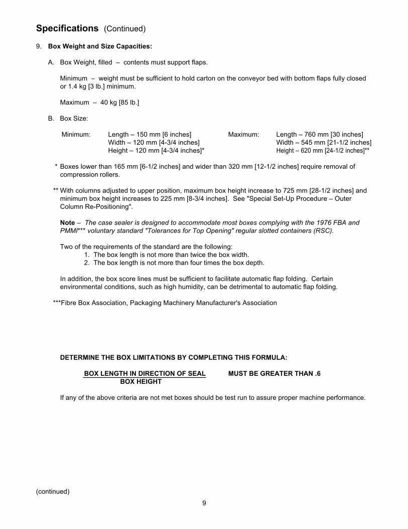
DETERMINE THE BOX LIMITATIONS BY COMPLETING THIS FORMULA:
BOX LENGTH IN DIRECTION OF SEAL MUST BE GREATER THAN .6BOX HEIGHT
If any of the above criteria are not met boxes should be test run to assure proper machine performance.
Specifications (Continued)
9. Box Weight and Size Capacities:
A. Box Weight, filled – contents must support flaps.
Minimum – weight must be sufficient to hold carton on the conveyor bed with bottom flaps fully closedor 1.4 kg [3 lb.] minimum.
Maximum – 40 kg [85 lb.]
B. Box Size:
Minimum: Length – 150 mm [6 inches] Maximum: Length – 760 mm [30 inches]Width – 120 mm [4-3/4 inches] Width – 545 mm [21-1/2 inches]Height – 120 mm [4-3/4 inches]* Height – 620 mm [24-1/2 inches]**
* Boxes lower than 165 mm [6-1/2 inches] and wider than 320 mm [12-1/2 inches] require removal ofcompression rollers.
** With columns adjusted to upper position, maximum box height increase to 725 mm [28-1/2 inches] andminimum box height increases to 225 mm [8-3/4 inches]. See "Special Set-Up Procedure – OuterColumn Re-Positioning".
Note – The case sealer is designed to accommodate most boxes complying with the 1976 FBA andPMMI*** voluntary standard "Tolerances for Top Opening" regular slotted containers (RSC).
Two of the requirements of the standard are the following:1. The box length is not more than twice the box width.2. The box length is not more than four times the box depth.
In addition, the box score lines must be sufficient to facilitate automatic flap folding. Certainenvironmental conditions, such as high humidity, can be detrimental to automatic flap folding.
***Fibre Box Association, Packaging Machinery Manufacturer's Association
10
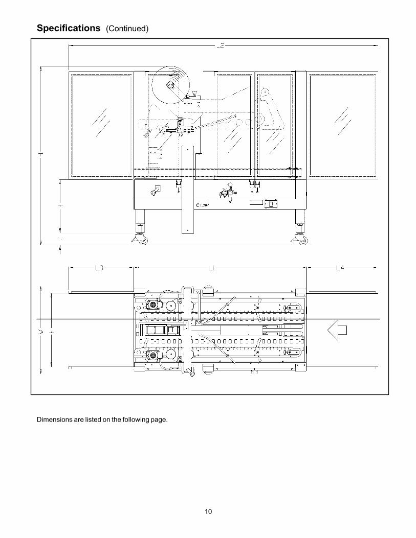
Specifications (Continued)
Dimensions are listed on the following page.
11
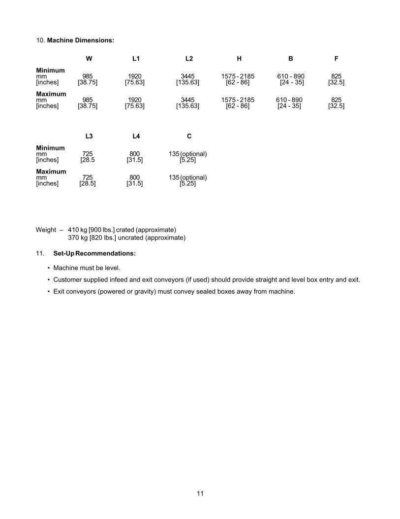
10. Machine Dimensions:
W L1 L2 H B F
Minimummm 985 1920 3445 1575 - 2185 610 - 890 825[inches] [38.75] [75.63] [135.63] [62 - 86] [24 - 35] [32.5]
Maximummm 985 1920 3445 1575 - 2185 610 - 890 825[inches] [38.75] [75.63] [135.63] [62 - 86] [24 - 35] [32.5]
Weight – 410 kg [900 lbs.] crated (approximate)370 kg [820 lbs.] uncrated (approximate)
11. Set-Up Recommendations:
• Machine must be level.
• Customer supplied infeed and exit conveyors (if used) should provide straight and level box entry and exit.
• Exit conveyors (powered or gravity) must convey sealed boxes away from machine.
L3 L4 C
Minimummm 725 800 135 (optional)[inches] [28.5 [31.5] [5.25]
Maximummm 725 800 135 (optional)[inches] [28.5] [31.5] [5.25]

12
Installation and Set-Up
Machine Set-Up
Receiving And Handling
After the machine has been uncrated, examine the case sealer for damage that might have occurred duringtransit. If damage is evident, file a damage claim immediately with the transportation company and alsonotify your 3M Representative.
It is recommended that the case sealer be set-up and operated with product before placing it in the productionline. This approach will allow your thorough review and familiarization with the 800af-s before subjecting it andoperating personnel to a production situation where time for set-up, adjustments, and operator training usuallybecomes limited.
The following instructions are presented in the order recommended for setting up and installing the case sealer.Following them step by step will result in an installation in your production line that best utilizes the many featuresbuilt into the case sealer. Refer to Figure 3-1 and 3-2 to identify the various components and controls of themachine.
IMPORTANT – Read "Warnings" before attempting to set up the case sealer for operation.
For future reference, record machine serial number on front cover of this instruction manual in the spaceprovided.
1. Follow "Unpacking Instructions" label attached to corrugated packing cover.
2. Use appropriate material handling equipment to remove the machine from the pallet and move it into position.
Whenever the machine is lifted with a fork truck, insure that the forks span completely across the machineframe and do not contact any wiring or mechanism under the machine frame. In some cases the lower tapinghead may need to be removed to avoid damage.
2. Remove and discard cable ties on upper head assembly.
3. Install the crank handle on the top of the left column, as shown in Figure 2-1A.
4. Install upper tape drum bracket on the top cross bar, as shown in Figure 2-1B.
5. Install the two infeed end guards. Attach the guards to the infeed end vertical masts, as shown inFigure 2-1C.
6. Raise upper head assembly (turn crank handle counterclockwise). Install the machine stops (from parts bag).Mount these stops as shown in Figure 2-1D using lowest hole position on brackets.
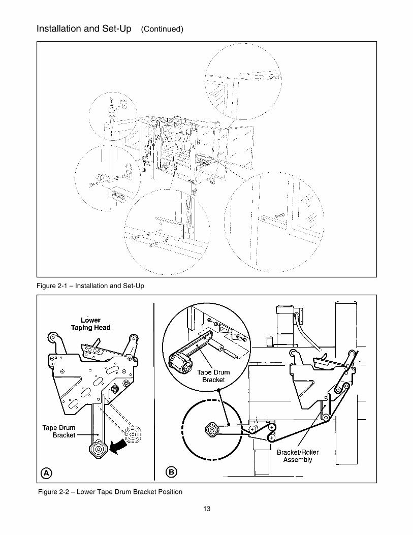
7. The lower tape drum bracket assembly is mounted on the lower head in the standard position. Ensure that thebracket assembly is mounted straight down, as shown in Figure 2-2A. The tape drum bracket assembly can bepivoted to provide clearance or for retrofit in certain cases.
Lower outboard tape roll mounting (alternate position) –
a. Remove lower taping head from machine.b. Remove existing tape drum bracket from taping head and replace with bracket/roller assembly (shipped
loose), Figure 2-2B. Replace taping head in machine.c. Install tape drum bracket (removed from taping head) on exit end of machine lower frame as shown in Figure
2-2B.
• To reduce the risk associated with muscle strain: − Use the appropriate rigging and material handling equipment when lifting or repositioning this equipment
WARNING
13
Installation and Set-Up (Continued)
Figure 2-1 – Installation and Set-Up
Figure 2-2 – Lower Tape Drum Bracket Position
14
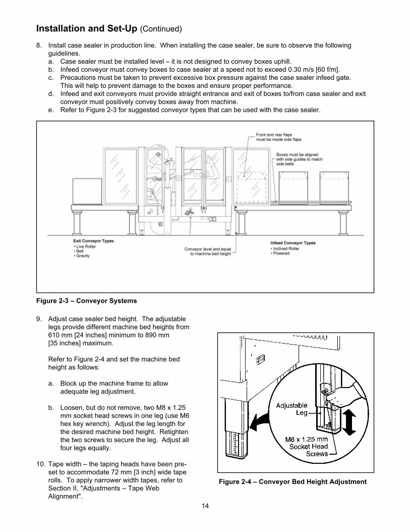
Installation and Set-Up (Continued)
8. Install case sealer in production line. When installing the case sealer, be sure to observe the followingguidelines.a. Case sealer must be installed level – it is not designed to convey boxes uphill.b. Infeed conveyor must convey boxes to case sealer at a speed not to exceed 0.30 m/s [60 f/m].c. Precautions must be taken to prevent excessive box pressure against the case sealer infeed gate.
This will help to prevent damage to the boxes and ensure proper performance.d. Infeed and exit conveyors must provide straight entrance and exit of boxes to/from case sealer and exit
conveyor must positively convey boxes away from machine.e. Refer to Figure 2-3 for suggested conveyor types that can be used with the case sealer.
9. Adjust case sealer bed height. The adjustablelegs provide different machine bed heights from610 mm [24 inches] minimum to 890 mm[35 inches] maximum.
Refer to Figure 2-4 and set the machine bedheight as follows:
a. Block up the machine frame to allowadequate leg adjustment.
b. Loosen, but do not remove, two M8 x 1.25mm socket head screws in one leg (use M6hex key wrench). Adjust the leg length forthe desired machine bed height. Retightenthe two screws to secure the leg. Adjust allfour legs equally.
10. Tape width – the taping heads have been pre-set to accommodate 72 mm [3 inch] wide taperolls. To apply narrower width tapes, refer toSection II, "Adjustments – Tape WebAlignment".
Figure 2-4 – Conveyor Bed Height Adjustment
Figure 2-3 – Conveyor Systems
15
Installation and Set-Up (Continued)
11. Box size capacity (height) – at its factorysetting, the case sealer handles box sizes up to620 mm [24-1/2 inches] maximum height. Iflarger capacity is needed, the machine can beadjusted to accommodate up to 725 mm [28-1/2inches] high boxes. Refer to "Special Set-UpProcedure – Outer ColumnRe-Positioning", for set-up information.
12. Drive Belt Height – drive belt assemblies can beraised 50 mm [2 inches] to provide betterconveying of tall boxes. Refer to "Special Set-Up Procedure – Changing Drive Belt Height".
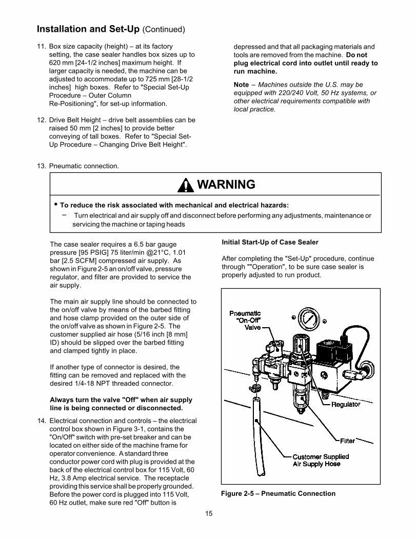
13. Pneumatic connection.
The case sealer requires a 6.5 bar gaugepressure [95 PSIG] 75 liter/min @21°C, 1.01bar [2.5 SCFM] compressed air supply. Asshown in Figure 2-5 an on/off valve, pressureregulator, and filter are provided to service theair supply.
The main air supply line should be connected tothe on/off valve by means of the barbed fittingand hose clamp provided on the outer side ofthe on/off valve as shown in Figure 2-5. Thecustomer supplied air hose (5/16 inch [8 mm]ID) should be slipped over the barbed fittingand clamped tightly in place.
If another type of connector is desired, thefitting can be removed and replaced with thedesired 1/4-18 NPT threaded connector.
Always turn the valve "Off" when air supplyline is being connected or disconnected.
Figure 2-5 – Pneumatic Connection
Initial Start-Up of Case Sealer
After completing the "Set-Up" procedure, continuethrough ""Operation", to be sure case sealer isproperly adjusted to run product.
Note – Machines outside the U.S. may beequipped with 220/240 Volt, 50 Hz systems, orother electrical requirements compatible withlocal practice.
14. Electrical connection and controls – the electricalcontrol box shown in Figure 3-1, contains the"On/Off" switch with pre-set breaker and can belocated on either side of the machine frame foroperator convenience. A standard threeconductor power cord with plug is provided at theback of the electrical control box for 115 Volt, 60Hz, 3.8 Amp electrical service. The receptacleproviding this service shall be properly grounded.Before the power cord is plugged into 115 Volt,60 Hz outlet, make sure red "Off" button is
depressed and that all packaging materials andtools are removed from the machine. Do notplug electrical cord into outlet until ready torun machine.
• To reduce the risk associated with mechanical and electrical hazards:− Turn electrical and air supply off and disconnect before performing any adjustments, maintenance or
servicing the machine or taping heads
WARNING

16
Operation
Refer to Figure 3-1 and 3-2 to acquaint yourself with the various components and controls of the 800af casesealer. Also see Figures 3-1 and 3-2 in Section II for taping head components.
Figure 3-1 – Case Sealer Components
• To reduce the risk associated with mechanical and electrical hazards:
Š Read, understand and follow all safety and operating instructions before operating or servicing the casesealer
WARNING

17
Operation (Continued)
Figure 3-2 – Controls, Valves and Switches1 Electrical "On/Off" Switch
The box drive belts are turned on and off (offbutton is red) with the electrical switch on theside of the machine guard at the infeed end.
Note – The air valve has provisions for lockout/tagoutaccording to plant regulations.
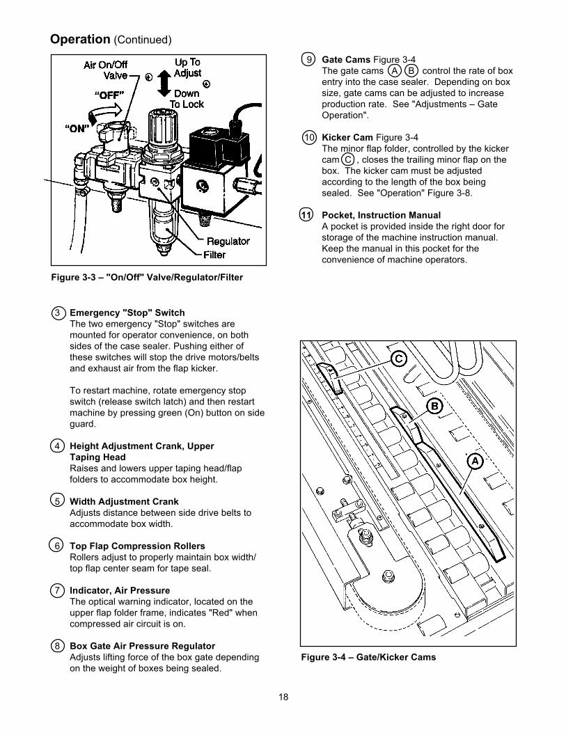
2 Main Air "On/Off" Valve/PressureRegulator/Filter – Figure 3-3This set of pneumatic components controls,regulates and filters plant air supply to the twoseparate control circuits of the case sealer.
Pressure Regulator regulates main air pressure to themachine to adjust pressure, pull knob up and turn –push down to lock setting.
Filter removes dirt and moisture from plant air before itenters the case sealer pneumatic circuits. If watercollects in bottom of bowl, lift up on the valve on thebottom of bowl to drain.
"On/Off" Valve – "On" turn to "SUP" – "Off" turn to"EXH".
Note – Turning air supply "Off" automatically bleedsair pressure from the case sealer air circuits.
Note – The case sealer has a circuit breaker locatedin the electrical enclosure on the lower right side ofthe machine frame. If circuit becomes overloadedand circuit breaker trips, unplug the machine electri-cal cord and determine cause of overload. After twominutes, remove the electrical control box cover andreset the circuit breaker by pressing the "Reset"button and then the "Start" button on the circuitbreaker. Replace the control box cover, plug ma-chine electrical cord into outlet and restart machineby pressing green "On" button.
WARNING• To reduce the risk associated with
mechanical and electrical hazards:− Allow only properly trained and qualified
personnel to operate and/or service thisequipment
− Turn electrical and air supply off anddisconnect before performing anyadjustments, maintenance or servicing themachine or taping heads
WARNING• To reduce the risk associated with mechanical
and electrical hazards:− Turn electrical and air supply off and
disconnect before performing any adjustments,maintenance or servicing the machine ortaping heads
18
Operation (Continued)
3 Emergency "Stop" SwitchThe two emergency "Stop" switches aremounted for operator convenience, on bothsides of the case sealer. Pushing either ofthese switches will stop the drive motors/beltsand exhaust air from the flap kicker.
To restart machine, rotate emergency stopswitch (release switch latch) and then restartmachine by pressing green (On) button on sideguard.
4 Height Adjustment Crank, UpperTaping HeadRaises and lowers upper taping head/flapfolders to accommodate box height.
5 Width Adjustment CrankAdjusts distance between side drive belts toaccommodate box width.
6 Top Flap Compression RollersRollers adjust to properly maintain box width/top flap center seam for tape seal.
7 Indicator, Air PressureThe optical warning indicator, located on theupper flap folder frame, indicates "Red" whencompressed air circuit is on.
8 Box Gate Air Pressure RegulatorAdjusts lifting force of the box gate dependingon the weight of boxes being sealed.
9 Gate Cams Figure 3-4The gate cams A B control the rate of boxentry into the case sealer. Depending on boxsize, gate cams can be adjusted to increaseproduction rate. See "Adjustments – GateOperation".
10 Kicker Cam Figure 3-4The minor flap folder, controlled by the kickercam C , closes the trailing minor flap on thebox. The kicker cam must be adjustedaccording to the length of the box beingsealed. See "Operation" Figure 3-8.
11 Pocket, Instruction ManualA pocket is provided inside the right door forstorage of the machine instruction manual.Keep the manual in this pocket for theconvenience of machine operators.
Figure 3-4 – Gate/Kicker Cams
Figure 3-3 – "On/Off" Valve/Regulator/Filter

19
Operation (Continued)
Tape Loading/Threading – Upper Taping Head
See Section II
Tape Loading/Threading – Lower Taping HeadWith Tape Drum On Taping Head
See Section II
Tape Loading/Threading – Lower Taping HeadWith Alternate Outboard Tape Drum
1. Raise upper taping head high enough to allowclearance for removing lower taping head.
2. Remove lower taping head from machine bedand install threading needle as explained inSection II.
3. Replace taping head back into machine.
4. Place tape roll on outboard tape drum withadhesive side down on lead end of tape. (Seattape roll fully against back flange of tape drum.)Thread tape through outboard tape rollers asshown in Figure 3-5 and adhere tape lead endto lower end of threading needle.
5. Complete tape threading as explained inSection II.
• To reduce the risk associated with mechanical and electrical hazards:− Turn electrical and air supply off and disconnect before performing any adjustments, maintenance or
servicing the machine or taping heads• To reduce the risk associated with impact hazards:
− Turn air supply off and be sure flap kicker is down before servicing− Never operate this equipment with safety interlocks or guarding removed
• To reduce the risk associated with sharp blade hazards:− Keep hands and fingers away from tape cutoff blades under orange blade guards. The blades are extremely
sharp• To reduce the risk associated with pinch and entanglement hazards:
− Do not leave the machine running while unattended− Never attempt to work on any part of the machine, load tape, or remove jammed boxes from the machine
while the machine is running− Keep hands, hair, loose clothing, and jewelry away from moving belts, taping heads, and flap kicker
WARNING
• To reduce the risk associated with musclestrain:
− Use proper body mechanics when removing orinstalling taping heads that are moderatelyheavy or may be considered awkward to lift
WARNING

20
Operation (Continued)
Figure 3-5 – Tape Threading With Alternate Outboard Tape Drum
Figure 3-6 – Box Size Set-Up
Box Size Set-Up
Figure 3-6
Open the side drive belts and raise the upper headassembly to accommodate the desired box widthand height.
Move the compression rolls as wide as possible.
21
Operation (Continued)
Figure 3-7 – Box Size Set-Up
Figure 3-8 – Box Size Set-Up
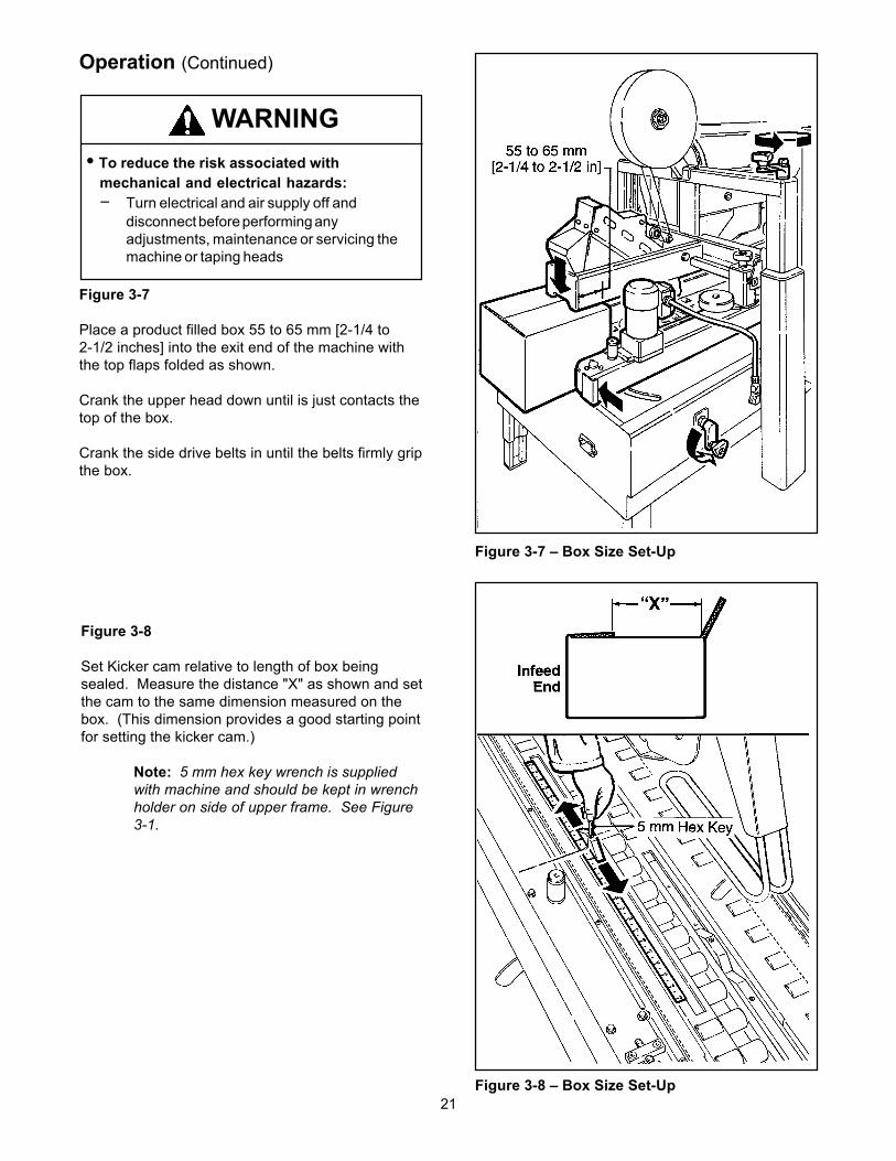
Figure 3-7
Place a product filled box 55 to 65 mm [2-1/4 to2-1/2 inches] into the exit end of the machine withthe top flaps folded as shown.
Crank the upper head down until is just contacts thetop of the box.
Crank the side drive belts in until the belts firmly gripthe box.
Figure 3-8
Set Kicker cam relative to length of box beingsealed. Measure the distance "X" as shown and setthe cam to the same dimension measured on thebox. (This dimension provides a good starting pointfor setting the kicker cam.)
Note: 5 mm hex key wrench is suppliedwith machine and should be kept in wrenchholder on side of upper frame. See Figure3-1.
• To reduce the risk associated withmechanical and electrical hazards:− Turn electrical and air supply off and
disconnect before performing anyadjustments, maintenance or servicing themachine or taping heads
WARNING
22
Operation (Continued)
Figure 3-9 – Box Size Set-Up
Figure 3-10 – Box Size Set-Up
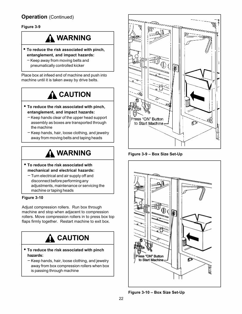
Figure 3-9
Place box at infeed end of machine and push intomachine until it is taken away by drive belts.
Figure 3-10
Adjust compression rollers. Run box throughmachine and stop when adjacent to compressionrollers. Move compression rollers in to press box topflaps firmly together. Restart machine to exit box.
• To reduce the risk associated with pinch,entanglement, and impact hazards:− Keep away from moving belts and
pneumatically controlled kicker
WARNING
• To reduce the risk associated with pinch,entanglement, and impact hazards:− Keep hands clear of the upper head support
assembly as boxes are transported throughthe machine
− Keep hands, hair, loose clothing, and jewelryaway from moving belts and taping heads
CAUTION
• To reduce the risk associated withmechanical and electrical hazards:− Turn electrical and air supply off and
disconnect before performing anyadjustments, maintenance or servicing themachine or taping heads
WARNING
• To reduce the risk associated with pinchhazards:− Keep hands, hair, loose clothing, and jewelry
away from box compression rollers when boxis passing through machine
CAUTION

23
Operation (Continued)
Figure 3-12 – Box Size Set-Up
Figure 3-11 – Box Size Set-Up
Figure 3-11
Run several test boxes through the machine, andobserve the flap kicking action. Adjust the kickercam so the kicker "kicks" earlier or later as required(refer to figure 3-8). In general, it is better to set thekicker to "kick" early because it contacts the flaphigher above the score-line which results in morereliable flap folding.
Figure 3-12
The upper side flap folding guides can be adjustedin or out to accommodate the width of the box. Foroptimum performance, the side flap folding guidesshould be adjusted to the narrowest position whichallows them to catch any side flaps that may bebent outward past vertical.
Note – Box flaps should not be bentoutward past vertical more than 15° whenentering case sealer.
• To reduce the risk associated with pinch,entanglement, and impact hazards:− Keep away from moving belts and pneumatically
controlled kicker
WARNING
24
Operation (Continued)
Note - Box drive motors are designed to run at a moderate temperature of 40° C [104° F]. In some cases theymay feel hot to the touch. Adjustment of the machine or taping heads are described in the "Adjustment"section of this manual.
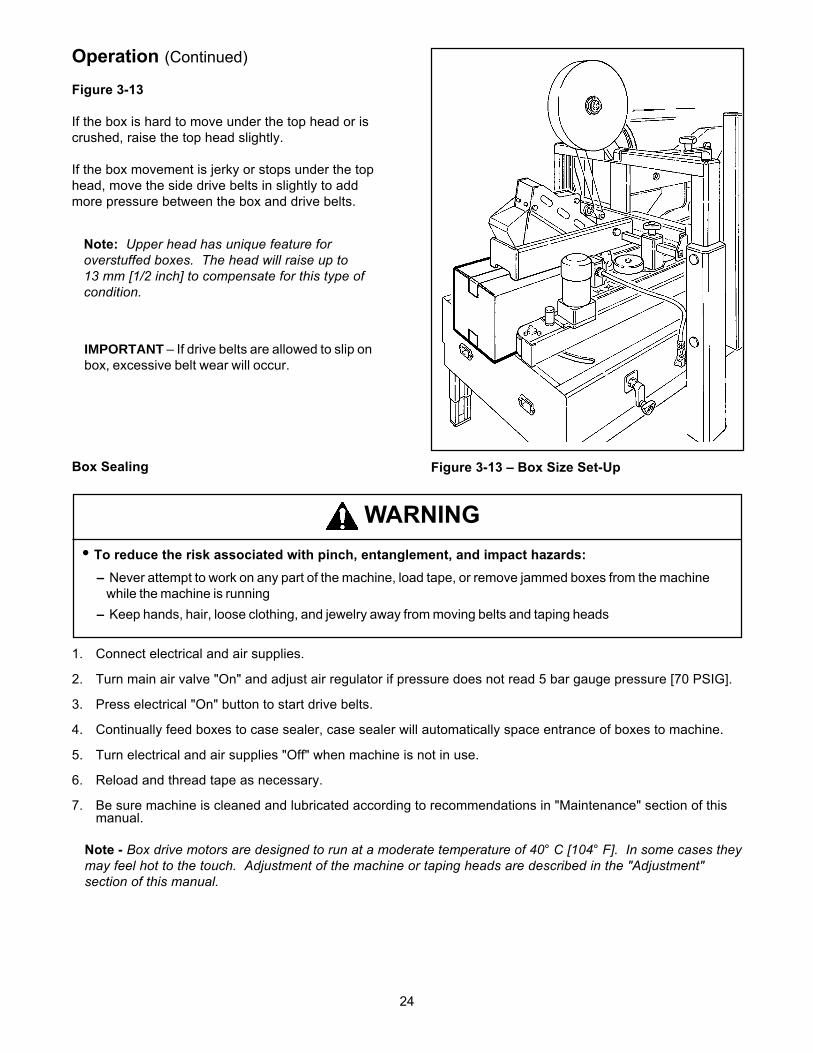
IMPORTANT – If drive belts are allowed to slip onbox, excessive belt wear will occur.
Figure 3-13 – Box Size Set-UpBox Sealing
1. Connect electrical and air supplies.
2. Turn main air valve "On" and adjust air regulator if pressure does not read 5 bar gauge pressure [70 PSIG].
3. Press electrical "On" button to start drive belts.
4. Continually feed boxes to case sealer, case sealer will automatically space entrance of boxes to machine.
5. Turn electrical and air supplies "Off" when machine is not in use.
6. Reload and thread tape as necessary.
7. Be sure machine is cleaned and lubricated according to recommendations in "Maintenance" section of thismanual.
Figure 3-13
If the box is hard to move under the top head or iscrushed, raise the top head slightly.
If the box movement is jerky or stops under the tophead, move the side drive belts in slightly to addmore pressure between the box and drive belts.
Note: Upper head has unique feature foroverstuffed boxes. The head will raise up to13 mm [1/2 inch] to compensate for this type ofcondition.
• To reduce the risk associated with pinch, entanglement, and impact hazards:– Never attempt to work on any part of the machine, load tape, or remove jammed boxes from the machine
while the machine is running– Keep hands, hair, loose clothing, and jewelry away from moving belts and taping heads
WARNING

25
Operation (Continued)
Box Jams
If a box is improperly fabricated or filled, if the machine is mis-adjusted for the box being run, or if boxes enterthe machine incorrectly, a box jam may occur. To clear a box jam, follow these steps:
1. Determine cause of box jam so corrective action can be taken to prevent reoccurrence.
2. Turn off machine.
3. Crank upper head up and/or drive belts out until box is free.
4. Carefully pull box out of machine.
5. Readjust upper head and drive belts according to "Machine Adjustment for Box Size" instructions.
6. Connect air and electrical supplies.
7. Turn machine "On" only when it is safe to do so!
• To reduce the risk associated with mechanical and electrical hazards:– Turn electrical and air supply off and disconnect before performing any adjustments, maintenance or
servicing the machine or taping heads• To reduce the risk associated with pinch, entanglement, and impact hazards:
– Never attempt to work on any part of the machine, load tape, or remove jammed boxes from the machinewhile the machine is running
WARNING
• To reduce the risk associated with sharp blade hazards:– Keep hands and fingers away from tape cutoff blades under orange blade guards. The blades areextremely sharp
• To reduce the risk associated with muscle strain:– Use proper body mechanics when removing or clearing jammed boxes from the machine
WARNING
26
Maintenance
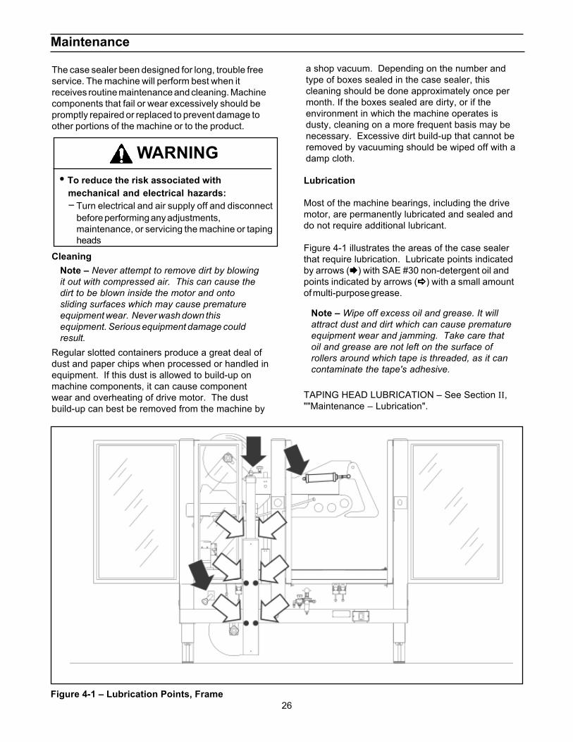
The case sealer been designed for long, trouble freeservice. The machine will perform best when itreceives routine maintenance and cleaning. Machinecomponents that fail or wear excessively should bepromptly repaired or replaced to prevent damage toother portions of the machine or to the product.
Figure 4-1 – Lubrication Points, Frame
CleaningNote – Never attempt to remove dirt by blowingit out with compressed air. This can cause thedirt to be blown inside the motor and ontosliding surfaces which may cause prematureequipment wear. Never wash down thisequipment. Serious equipment damage couldresult.
Regular slotted containers produce a great deal ofdust and paper chips when processed or handled inequipment. If this dust is allowed to build-up onmachine components, it can cause componentwear and overheating of drive motor. The dustbuild-up can best be removed from the machine by
Note – Wipe off excess oil and grease. It willattract dust and dirt which can cause prematureequipment wear and jamming. Take care thatoil and grease are not left on the surface ofrollers around which tape is threaded, as it cancontaminate the tape's adhesive.
a shop vacuum. Depending on the number andtype of boxes sealed in the case sealer, thiscleaning should be done approximately once permonth. If the boxes sealed are dirty, or if theenvironment in which the machine operates isdusty, cleaning on a more frequent basis may benecessary. Excessive dirt build-up that cannot beremoved by vacuuming should be wiped off with adamp cloth.
Lubrication
Most of the machine bearings, including the drivemotor, are permanently lubricated and sealed anddo not require additional lubricant.
Figure 4-1 illustrates the areas of the case sealerthat require lubrication. Lubricate points indicatedby arrows ( ) with SAE #30 non-detergent oil andpoints indicated by arrows ( ) with a small amountof multi-purpose grease.
TAPING HEAD LUBRICATION – See Section II,""Maintenance – Lubrication".
• To reduce the risk associated withmechanical and electrical hazards:− Turn electrical and air supply off and disconnect
before performing any adjustments,maintenance, or servicing the machine or tapingheads
WARNING
27
Maintenance (Continued)
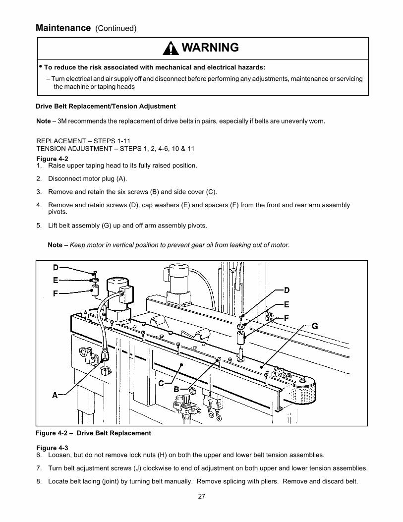
Drive Belt Replacement/Tension Adjustment
Note – 3M recommends the replacement of drive belts in pairs, especially if belts are unevenly worn.
REPLACEMENT – STEPS 1-11TENSION ADJUSTMENT – STEPS 1, 2, 4-6, 10 & 11Figure 4-21. Raise upper taping head to its fully raised position.
2. Disconnect motor plug (A).
3. Remove and retain the six screws (B) and side cover (C).
4. Remove and retain screws (D), cap washers (E) and spacers (F) from the front and rear arm assemblypivots.
5. Lift belt assembly (G) up and off arm assembly pivots.
Note – Keep motor in vertical position to prevent gear oil from leaking out of motor.
Figure 4-2 – Drive Belt Replacement
Figure 4-36. Loosen, but do not remove lock nuts (H) on both the upper and lower belt tension assemblies.
7. Turn belt adjustment screws (J) clockwise to end of adjustment on both upper and lower tension assemblies.
8. Locate belt lacing (joint) by turning belt manually. Remove splicing with pliers. Remove and discard belt.
• To reduce the risk associated with mechanical and electrical hazards:– Turn electrical and air supply off and disconnect before performing any adjustments, maintenance or servicing
the machine or taping heads
WARNING
28
Maintenance (Continued)
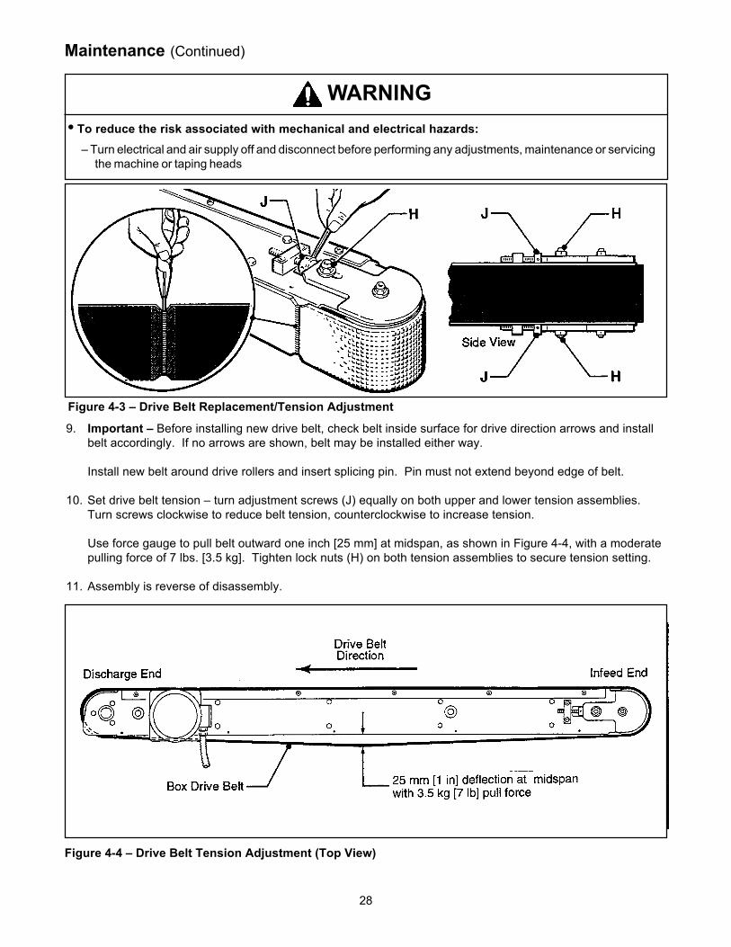
9. Important – Before installing new drive belt, check belt inside surface for drive direction arrows and installbelt accordingly. If no arrows are shown, belt may be installed either way.
Install new belt around drive rollers and insert splicing pin. Pin must not extend beyond edge of belt.
10. Set drive belt tension – turn adjustment screws (J) equally on both upper and lower tension assemblies.Turn screws clockwise to reduce belt tension, counterclockwise to increase tension.
Use force gauge to pull belt outward one inch [25 mm] at midspan, as shown in Figure 4-4, with a moderatepulling force of 7 lbs. [3.5 kg]. Tighten lock nuts (H) on both tension assemblies to secure tension setting.
11. Assembly is reverse of disassembly.
Figure 4-4 – Drive Belt Tension Adjustment (Top View)
Figure 4-3 – Drive Belt Replacement/Tension Adjustment
• To reduce the risk associated with mechanical and electrical hazards:– Turn electrical and air supply off and disconnect before performing any adjustments, maintenance or servicing
the machine or taping heads
WARNING

29
Maintenance (Continued)
Circuit Breaker
The case sealer is equipped with a circuit breakerwhich trips if the motors are overloaded. Locatedinside the electrical control box on the side of themachine, the circuit breaker has been pre-set at2.2 Amps and requires no further maintenance.
Air Line Filter – Figure 4-5
Periodically check the air line filter to drain water andclean as necessary. Do not allow water to go abovethe filter element.
Figure 4-5 – Air Line FilterIf circuit is overloaded and circuit breaker trips,unplug machine from electrical power:
1. Determine cause of overload and correct.2. Remove electrical enclosure cover.3. Press the red "Reset" button and then the
green "Start" button.4. Replace cover.5. Plug in machine. Wait two minutes.6. Press machine "On" button, on the side
guard, to resume case sealing.
Knife Replacement, Taping Head
See Section II, "Maintenance – Blade (Knife)Replacement".
• To reduce the risk associated with mechanical and electrical hazards:– Turn electrical and air supply off and disconnect before performing any adjustments, maintenance or servicing
the machine or taping heads
WARNING
• To reduce the risk associated withmechanical and electrical hazards:– Allow only properly trained and qualified
personnel to operate and/or service thisequipment
WARNING
30
Figure 5-1 – Gate Cams
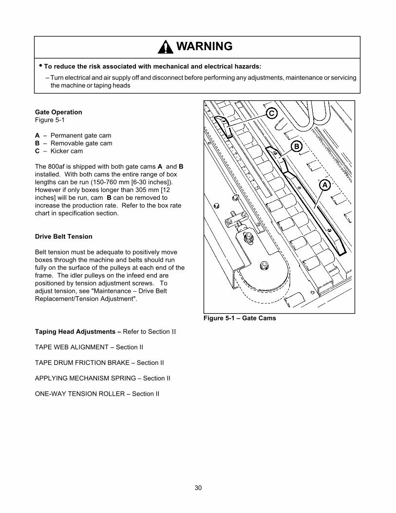
Gate OperationFigure 5-1
A – Permanent gate camB – Removable gate camC – Kicker cam
The 800af is shipped with both gate cams A and Binstalled. With both cams the entire range of boxlengths can be run (150-760 mm [6-30 inches]).However if only boxes longer than 305 mm [12inches] will be run, cam B can be removed toincrease the production rate. Refer to the box ratechart in specification section.
Drive Belt Tension
Belt tension must be adequate to positively moveboxes through the machine and belts should runfully on the surface of the pulleys at each end of theframe. The idler pulleys on the infeed end arepositioned by tension adjustment screws. Toadjust tension, see "Maintenance – Drive BeltReplacement/Tension Adjustment".
Taping Head Adjustments – Refer to Section II
TAPE WEB ALIGNMENT – Section II
TAPE DRUM FRICTION BRAKE – Section II
APPLYING MECHANISM SPRING – Section II
ONE-WAY TENSION ROLLER – Section II
• To reduce the risk associated with mechanical and electrical hazards:– Turn electrical and air supply off and disconnect before performing any adjustments, maintenance or servicing
the machine or taping heads
WARNING
31
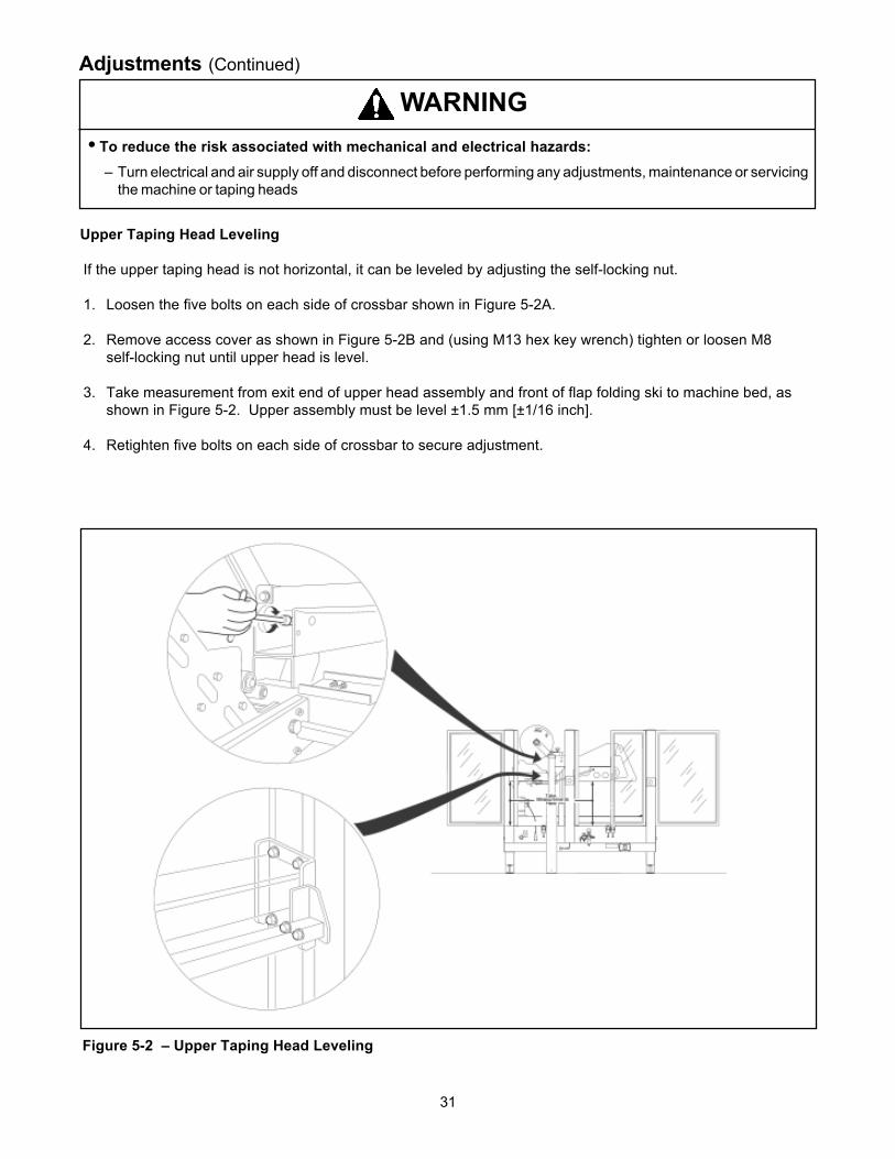
Figure 5-2 – Upper Taping Head Leveling
Adjustments (Continued)
Upper Taping Head Leveling
If the upper taping head is not horizontal, it can be leveled by adjusting the self-locking nut.
1. Loosen the five bolts on each side of crossbar shown in Figure 5-2A.
2. Remove access cover as shown in Figure 5-2B and (using M13 hex key wrench) tighten or loosen M8self-locking nut until upper head is level.
3. Take measurement from exit end of upper head assembly and front of flap folding ski to machine bed, asshown in Figure 5-2. Upper assembly must be level ±1.5 mm [±1/16 inch].
4. Retighten five bolts on each side of crossbar to secure adjustment.
• To reduce the risk associated with mechanical and electrical hazards:– Turn electrical and air supply off and disconnect before performing any adjustments, maintenance or servicing
the machine or taping heads
WARNING

32
Adjustments (Continued)
Gate Pressure RegulatorFigure 5-3
The gate air pressure is controlled by a regulatormounted under the machine frame. This providesadjustment of the gate lifting force. When light weightboxes are being run the gate pressure can bereduced to minimize lifting of the box.
Gate Stroke SettingFigure 5-4
The machine is initially set at the maximum gate liftof 25 mm [1 inch]. However this can be reduced ifneeded for special situations. To do this, removethe center roller section and turn the stop nutsclockwise until the desired lift is achieved.
Figure 5-3 – Gate Pressure Regulator
Figure 5-4 – Gate Stroke Setting
• To reduce the risk associated withmechanical and electrical hazards:– Turn electrical and air supply off and
disconnect before performing anyadjustments, maintenance or servicing themachine or taping heads
WARNING

33
THIS PAGE IS BLANK

34
Special Set-Up Procedure
Changing Drive Belt Height
The drive belt assemblies can be raised 50 mm[2 inches] to provide better conveying of tall boxes.This change increase the minimum box heightthat can be taped to 190 mm [7-1/4 inches].
DISASSEMBLY – Figure 6-1
1. Using the height adjustment crank, raise theupper taping head to its fully raised position.
2. Remove and retain the M6 x 16 flat head capscrew (A), special washer (B) and spacer (C)from the front and rear arm assembly pivots.
3. Lift drive belt assembly (D) up off the armassembly pivots.
Note – Keep motor in vertical position toprevent gear oil from leaking out of motor.
REASSEMBLY – Figure 6-2
4. Reassemble the spacer (C) onto the front andrear arm assembly pivots first.
5. Install the belt drive assembly (D) onto thepivots and secure with special washers (B) andM6 x 16 flat head cap screws (A).
Note – Both drive belt assemblies must beinstalled at the same operating height.
Figure 6-1 – Drive Belt Height, Disassembly
Figure 6-2 – Drive Belt Height, Reassembly
• To reduce the risk associated withmechanical and electrical hazards:– Turn electrical and air supply off and
disconnect before performing anyadjustments, maintenance or servicing themachine or taping heads
WARNING

35
Special Set-Up Procedure (Continued)
Outer Column Re-Positioning (Refer to Figure 6-4)
Moving the outer columns up one set of mounting holes increases the maximum box size handled by the casesealer from 620 mm [24-1/2 inches] to 725 mm [28-1/2 inches].
To move the outer columns up one set of mounting holes:
1. Crank side drive belts to full open position.
2. Crank upper taping head frame assembly up approximately 330 mm [13 inches] from machine bed.
3. Place solid blocks approximately 305 mm [12 inches] high beneath upper taping head frame at rear of tapinghead and under front flap folding ski (Figure 6-4A).
Note – Blocks (front and rear) must be the same height in order to keep upper frame level.
4. Crank upper taping head frame down until weight of upper frame is fully on blocks.
5. Remove and retain six mounting screws in each outer column assembly (Figure 6-4B).
6. Crank outer column up 100 mm [4 inches] and re-install six (6) screws in each column. Tighten screws.
7. Crank upper taping head up and remove blocks.
8. Check horizontal alignment of upper taping head frame and adjust as described in "Adjustments – UpperTaping Head Leveling".
IMPORTANT– A second person should assist with this part of set-up to hold (steady) upper frame untilcolumns are re-positioned and column screws are installed and tightened.
• To reduce the risk associated with muscle strain:– Use the appropriate rigging and material handling equipment when lifting or repositioning this equipment.
WARNING

36
Special Set-Up Procedure (Continued)
Figure 6-4 – Column Re-Positioning
37
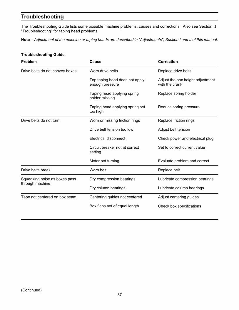
TroubleshootingThe Troubleshooting Guide lists some possible machine problems, causes and corrections. Also see Section II"Troubleshooting" for taping head problems.
Note – Adjustment of the machine or taping heads are described in "Adjustments", Section I and II of this manual.
Problem
Drive belts do not convey boxes
Drive belts do not turn
Drive belts break
Squeaking noise as boxes passthrough machine
Tape not centered on box seam
(Continued)
Cause
Worn drive belts
Top taping head does not applyenough pressure
Taping head applying springholder missing
Taping head applying spring settoo high
Worn or missing friction rings
Drive belt tension too low
Electrical disconnect
Circuit breaker not at correctsetting
Motor not turning
Worn belt
Dry compression bearings
Dry column bearings
Centering guides not centered
Box flaps not of equal length
Correction
Replace drive belts
Adjust the box height adjustmentwith the crank
Replace spring holder
Reduce spring pressure
Replace friction rings
Adjust belt tension
Check power and electrical plug
Set to correct current value
Evaluate problem and correct
Replace belt
Lubricate compression bearings
Lubricate column bearings
Adjust centering guides
Check box specifications
Troubleshooting Guide
38
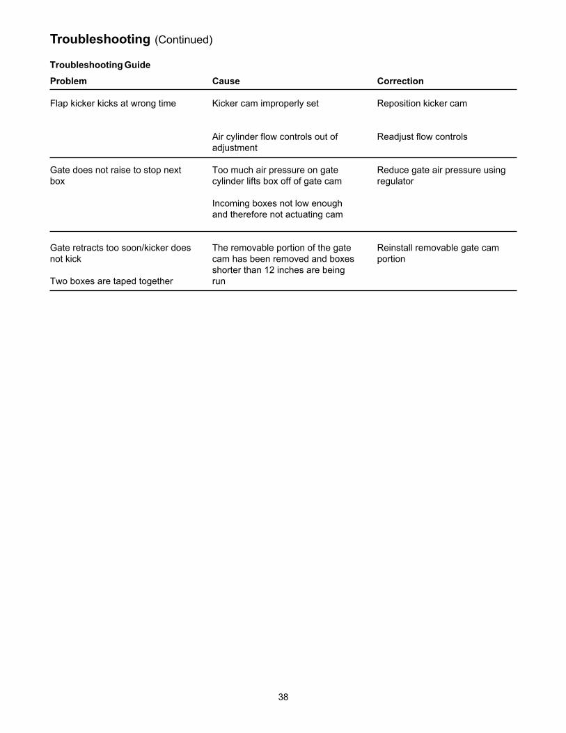
Troubleshooting (Continued)
Troubleshooting Guide
Problem
Flap kicker kicks at wrong time
Gate does not raise to stop nextbox
Gate retracts too soon/kicker doesnot kick
Two boxes are taped together
Cause
Kicker cam improperly set
Air cylinder flow controls out ofadjustment
Too much air pressure on gatecylinder lifts box off of gate cam
Incoming boxes not low enoughand therefore not actuating cam
The removable portion of the gatecam has been removed and boxesshorter than 12 inches are beingrun
Correction
Reposition kicker cam
Readjust flow controls
Reduce gate air pressure usingregulator
Reinstall removable gate camportion

39
Pneumatic Diagram
Figure 7-1 – Pneumatic Diagram
• To reduce the risk associated with mechanical and electrical hazards:– Turn electrical and air supply off and disconnect before performing any adjustments, maintenance or servicing
the machine or taping heads
WARNING
40
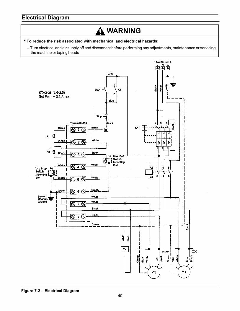
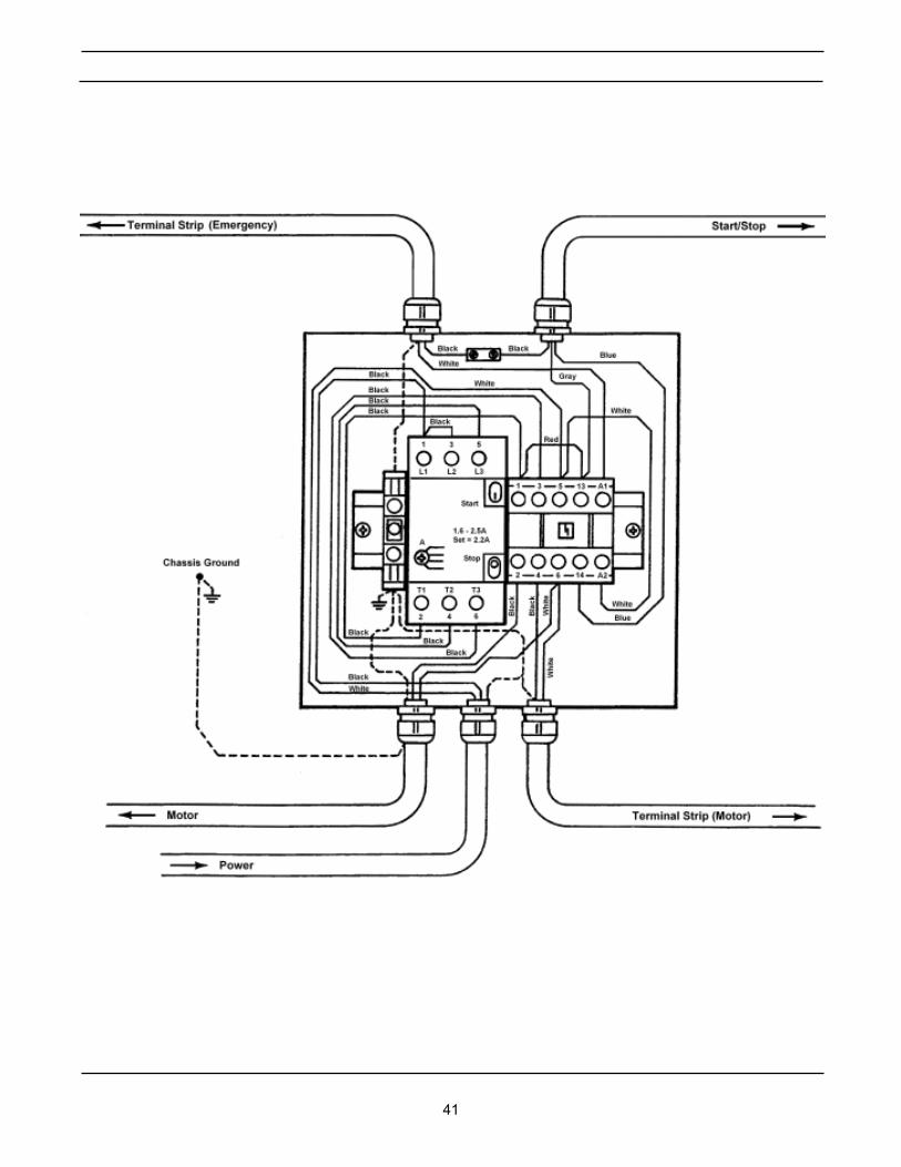
Electrical Diagram
Figure 7-2 – Electrical Diagram
• To reduce the risk associated with mechanical and electrical hazards:– Turn electrical and air supply off and disconnect before performing any adjustments, maintenance or servicing
the machine or taping heads
WARNING
41

42
THIS PAGE IS BLANK

43
Spare and Miscellaneous Parts
Spare Parts
The following parts are normal wear items and should be ordered and kept on hand as used.
Qty. Ref. No. Part Number Description
2 10472-66 (Sec. I) 78-8076-4865-0 Belt – Drive W/Pin
Qty. Ref. No. Part Number Description
1 A4-14-12 (Sec. II) 78-8060-8237-2 Spring - Upper Extension1 A4-20-12 (Sec. II) 78-8060-8394-1 Spring - Lower Extension2 A4-16-3 (Sec. II) 78-8060-8419-6 Knife – 65 mm/2.56 Inch4 AY-16-14 (Sec. II) 78-8060-8340-4 Spring – Cutting
Tool and Parts Kit
A tool kit, part number 78-8054-8732-5, is available as a stock item. The kit contains the necessary open end andhex socket wrenches for use with the metric fasteners on the case sealer. The threading tool, part number 78-8076-4726-4 contained in above kit is also available as a replacement stock item.
Replacement Parts Ordering Information and Service
Refer to first page of this manual "Replacement Parts and Service Information" for parts ordering information.
Label Kit
In the event that any labels are damaged or destroyed, they must be replaced to ensure operator safety. A labelkit, part number 78-8113-6876-6 is available as a stock item. It contains all the safety labels used on the 800afAdjustable Case Sealer. Labels can also be purchased separately. See Parts Drawing/List, pages 86 and 87.
In addition, a tool/spare parts kit supplied with the 800af3 Adjustable Case Sealer contains the following spareparts:
All the above listed parts can be ordered separately and when used should be ordered and kept on hand forspares.
44
Options/Accessories
Part Number Option/Accessory
70-0064-0379-7 Caster Kit Attachment
78-8060-8156-4 AccuGlide SST 2 Inch Upper Taping Head, Type 18900
78-8060-8157-2 AccuGlide SST 2 Inch Lower Taping Head, Type 18900
For additional information on the options/accessories listed below, contact your 3M Representative.
45
Replacement Parts – Illustrations and Parts Lists800af-s Stainless Steel Adjustable Case Sealer, Type 10500 (2 Inch Width Taping Heads)
Frame Assemblies
1. Refer to Frame Assemblies Figure to find all the parts illustrations identified by figure numbers.
2. Refer to the Figure or Figures to determine the individual parts required and the parts referencenumber.
3. The replacement parts list, that follows each illustration, includes the part number and part descriptionfor the parts in that illustration.
Note – The complete description has been included for standard fasteners and somecommercially available components.
4. Refer to the first page of this instruction manual “Replacement Parts and Service Information” forreplacement parts ordering information.
IMPORTANT – Not all the parts listed are normally stocked items. Some parts or assem-blies shown are available only on a special order basis. Contact 3M/Tape Dispenser Partsto confirm item availability.

46
THIS PAGE IS BLANK

47
800af Adjustable Case Sealer
Frame Assemblies
48
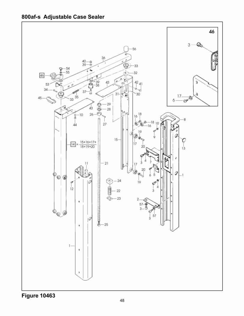
800af-s Adjustable Case Sealer
Figure 10463
49
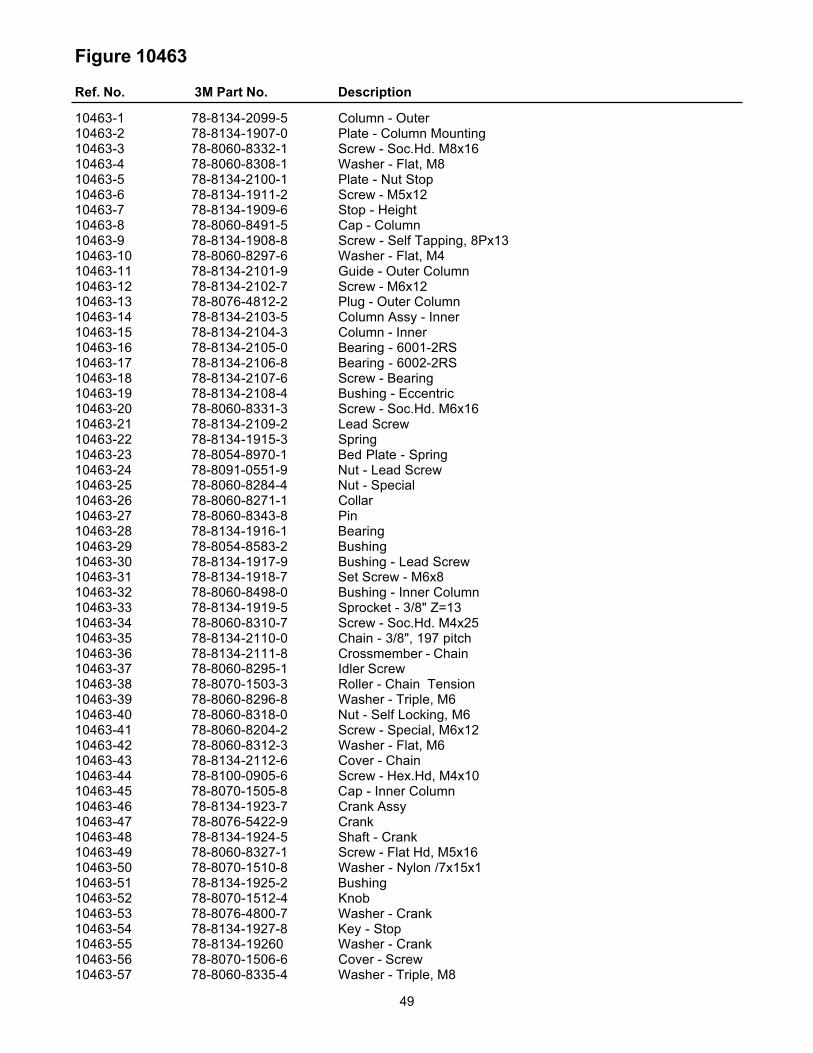
Figure 10463
Ref. No. 3M Part No. Description
10463-1 78-8134-2099-5 Column - Outer10463-2 78-8134-1907-0 Plate - Column Mounting10463-3 78-8060-8332-1 Screw - Soc.Hd. M8x1610463-4 78-8060-8308-1 Washer - Flat, M810463-5 78-8134-2100-1 Plate - Nut Stop10463-6 78-8134-1911-2 Screw - M5x1210463-7 78-8134-1909-6 Stop - Height10463-8 78-8060-8491-5 Cap - Column10463-9 78-8134-1908-8 Screw - Self Tapping, 8Px1310463-10 78-8060-8297-6 Washer - Flat, M410463-11 78-8134-2101-9 Guide - Outer Column10463-12 78-8134-2102-7 Screw - M6x1210463-13 78-8076-4812-2 Plug - Outer Column10463-14 78-8134-2103-5 Column Assy - Inner10463-15 78-8134-2104-3 Column - Inner10463-16 78-8134-2105-0 Bearing - 6001-2RS10463-17 78-8134-2106-8 Bearing - 6002-2RS10463-18 78-8134-2107-6 Screw - Bearing10463-19 78-8134-2108-4 Bushing - Eccentric10463-20 78-8060-8331-3 Screw - Soc.Hd. M6x1610463-21 78-8134-2109-2 Lead Screw10463-22 78-8134-1915-3 Spring10463-23 78-8054-8970-1 Bed Plate - Spring10463-24 78-8091-0551-9 Nut - Lead Screw10463-25 78-8060-8284-4 Nut - Special10463-26 78-8060-8271-1 Collar10463-27 78-8060-8343-8 Pin10463-28 78-8134-1916-1 Bearing10463-29 78-8054-8583-2 Bushing10463-30 78-8134-1917-9 Bushing - Lead Screw10463-31 78-8134-1918-7 Set Screw - M6x810463-32 78-8060-8498-0 Bushing - Inner Column10463-33 78-8134-1919-5 Sprocket - 3/8" Z=1310463-34 78-8060-8310-7 Screw - Soc.Hd. M4x2510463-35 78-8134-2110-0 Chain - 3/8", 197 pitch10463-36 78-8134-2111-8 Crossmember - Chain10463-37 78-8060-8295-1 Idler Screw10463-38 78-8070-1503-3 Roller - Chain Tension10463-39 78-8060-8296-8 Washer - Triple, M610463-40 78-8060-8318-0 Nut - Self Locking, M610463-41 78-8060-8204-2 Screw - Special, M6x1210463-42 78-8060-8312-3 Washer - Flat, M610463-43 78-8134-2112-6 Cover - Chain10463-44 78-8100-0905-6 Screw - Hex.Hd, M4x1010463-45 78-8070-1505-8 Cap - Inner Column10463-46 78-8134-1923-7 Crank Assy10463-47 78-8076-5422-9 Crank10463-48 78-8134-1924-5 Shaft - Crank10463-49 78-8060-8327-1 Screw - Flat Hd, M5x1610463-50 78-8070-1510-8 Washer - Nylon /7x15x110463-51 78-8134-1925-2 Bushing10463-52 78-8070-1512-4 Knob10463-53 78-8076-4800-7 Washer - Crank10463-54 78-8134-1927-8 Key - Stop10463-55 78-8134-19260 Washer - Crank10463-56 78-8070-1506-6 Cover - Screw10463-57 78-8060-8335-4 Washer - Triple, M8

50Figure 10464
800af-s Adjustable Case Sealer
51
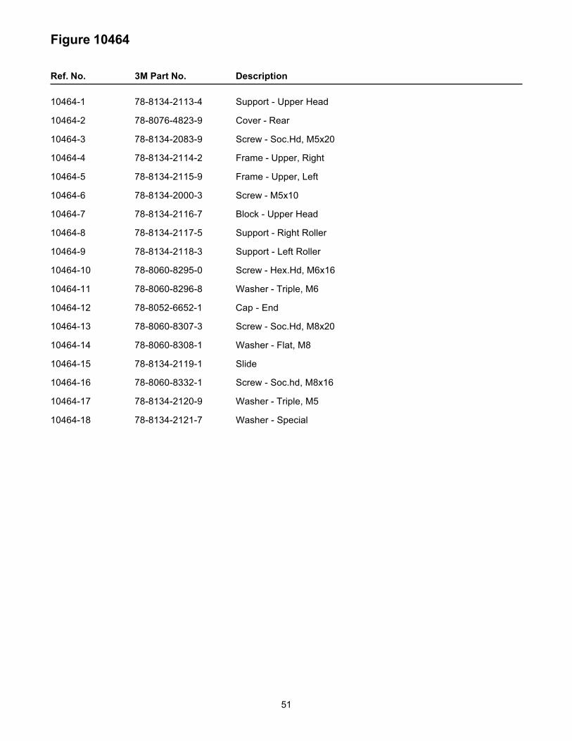
Figure 10464
Ref. No. 3M Part No. Description
10464-1 78-8134-2113-4 Support - Upper Head
10464-2 78-8076-4823-9 Cover - Rear
10464-3 78-8134-2083-9 Screw - Soc.Hd, M5x20
10464-4 78-8134-2114-2 Frame - Upper, Right
10464-5 78-8134-2115-9 Frame - Upper, Left
10464-6 78-8134-2000-3 Screw - M5x10
10464-7 78-8134-2116-7 Block - Upper Head
10464-8 78-8134-2117-5 Support - Right Roller
10464-9 78-8134-2118-3 Support - Left Roller
10464-10 78-8060-8295-0 Screw - Hex.Hd, M6x16
10464-11 78-8060-8296-8 Washer - Triple, M6
10464-12 78-8052-6652-1 Cap - End
10464-13 78-8060-8307-3 Screw - Soc.Hd, M8x20
10464-14 78-8060-8308-1 Washer - Flat, M8
10464-15 78-8134-2119-1 Slide
10464-16 78-8060-8332-1 Screw - Soc.hd, M8x16
10464-17 78-8134-2120-9 Washer - Triple, M5
10464-18 78-8134-2121-7 Washer - Special

52Figure 10465
800af-s Adjustable Case Sealer
53
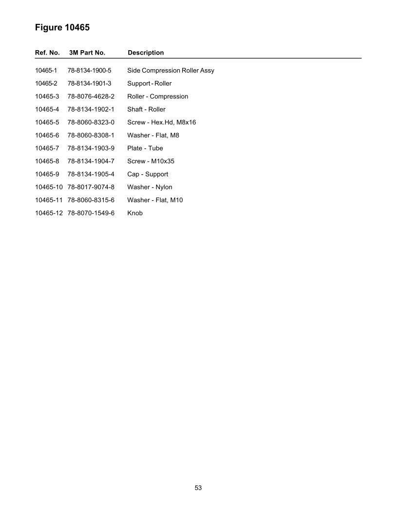
Figure 10465
Ref. No. 3M Part No. Description
10465-1 78-8134-1900-5 Side Compression Roller Assy
10465-2 78-8134-1901-3 Support - Roller
10465-3 78-8076-4628-2 Roller - Compression
10465-4 78-8134-1902-1 Shaft - Roller
10465-5 78-8060-8323-0 Screw - Hex.Hd, M8x16
10465-6 78-8060-8308-1 Washer - Flat, M8
10465-7 78-8134-1903-9 Plate - Tube
10465-8 78-8134-1904-7 Screw - M10x35
10465-9 78-8134-1905-4 Cap - Support
10465-10 78-8017-9074-8 Washer - Nylon
10465-11 78-8060-8315-6 Washer - Flat, M10
10465-12 78-8070-1549-6 Knob
54
800af-s Adjustable Case Sealer
Figure 10467
55
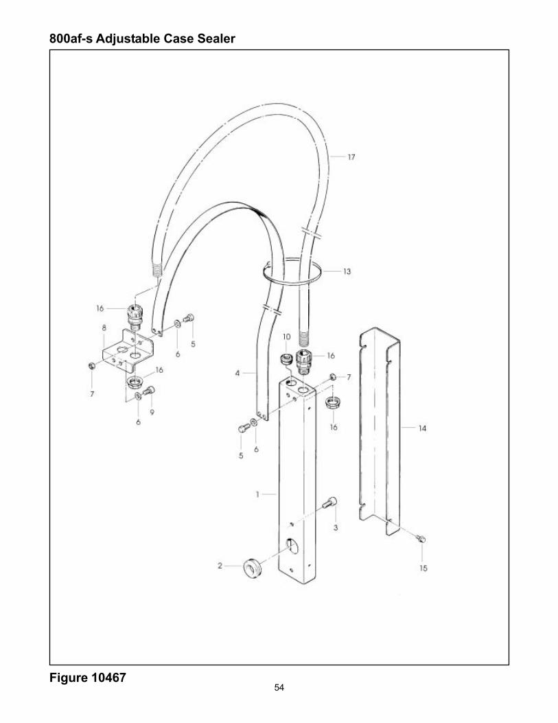
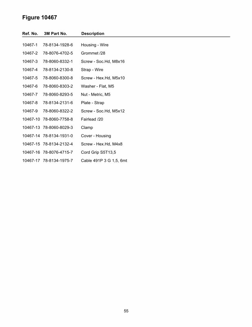
Figure 10467
Ref. No. 3M Part No. Description
10467-1 78-8134-1928-6 Housing - Wire
10467-2 78-8076-4702-5 Grommet /28
10467-3 78-8060-8332-1 Screw - Soc.Hd, M8x16
10467-4 78-8134-2130-8 Strap - Wire
10467-5 78-8060-8300-8 Screw - Hex.Hd, M5x10
10467-6 78-8060-8303-2 Washer - Flat, M5
10467-7 78-8060-8293-5 Nut - Metric, M5
10467-8 78-8134-2131-6 Plate - Strap
10467-9 78-8060-8322-2 Screw - Soc.Hd, M5x12
10467-10 78-8060-7758-8 Fairlead /20
10467-13 78-8060-8029-3 Clamp
10467-14 78-8134-1931-0 Cover - Housing
10467-15 78-8134-2132-4 Screw - Hex.Hd, M4x8
10467-16 78-8076-4715-7 Cord Grip S5T13,5
10467-17 78-8134-1975-7 Cable 491P 3 G 1,5, 6mt
56
800af-s Adjustable Case Sealer
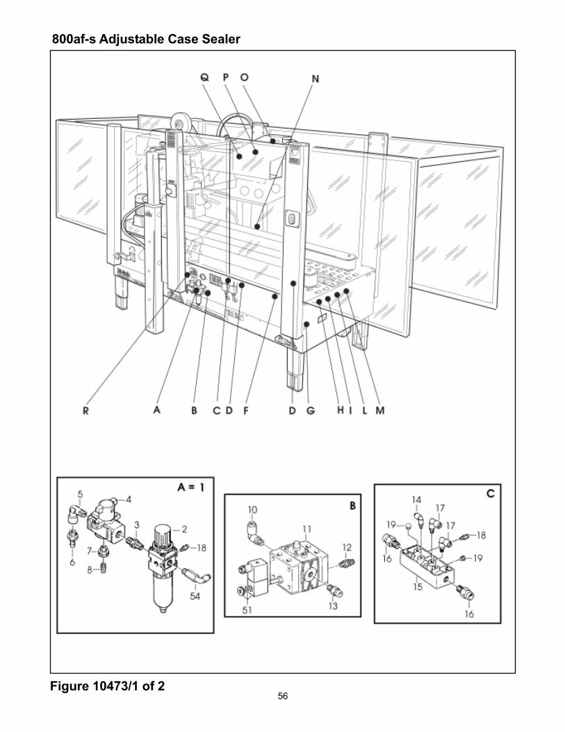
Figure 10473/1 of 2

57
Figure 10473 (Page 1 of 2)
Ref. No. 3M Part No. Description
10473-1 78-8091-0424-9 Filter/Regulator Assy
10473-2 26-1014-4558-8 Filter/Regulator W/Metal Bowl
10473-3 78-8060-7899-0 Nipple RA 012 1/4"-1/4"
10473-4 78-8091-0715-0 Valve - EVHS-4500-F02-X116
10473-5 78-8060-7900-6 Union RA 022 1/4"-1/4"
10473-6 26-1005-6897-6 Hose Connector
10473-7 78-8076-4670-4 Reduction 3/8"-1/8"
10473-8 26-1005-6890-1 Muffler 1/8"
10473-9 78-8054-8838-0 Gauge - Air
10473-10 78-8076-4885-8 Elbow KQL08-02S
10473-11 78-8091-0419-9 Valve - MFHE—3-1/4"
10473-12 78-8076-4886-6 Muffler 1/4"
10473-13 78-8076-4887-4 Union KQH08-02S
10473-14 78-8076-4888-2 Elbow KQL04-01S
10473-15 78-8060-7651-5 Union FR-8-1/8"
10473-16 78-8076-4889-0 Union KHQ08-03S
10473-17 78-8076-4890-8 Elbow KQL06-01S
10473-18 78-8076-4891-6 Union KQH04-01S
10473-19 78-8060-7690-3 Cap
10473-20 26-1005-6358-9 3-Way Valve
10473-21 78-8076-4892-4 Elbow KQL04-M5
10473-22 78-8091-0423-1 Gauge W/Support
10473-23 78-8060-7656-4 Valve - One Shot
10473-24 78-8076-4894-0 Pressure Regulator
10473-25 78-8076-4895-7 Elbow KQL06-02S
10473-26 78-8076-4896-5 Union KQH06-02S
10473-27 78-8076-4677-9 Valve - One Shot

58
800af-s Adjustable Case Sealer
Figure 10473/2 of 2
59
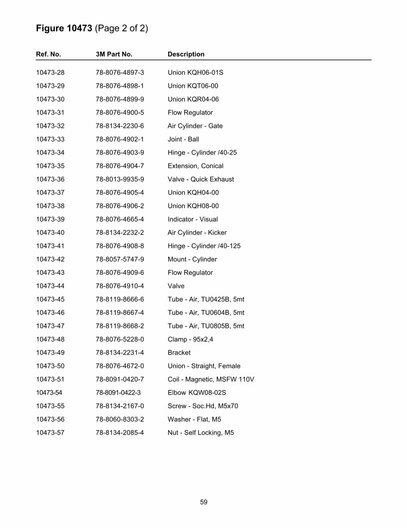
Figure 10473 (Page 2 of 2)
Ref. No. 3M Part No. Description
10473-28 78-8076-4897-3 Union KQH06-01S
10473-29 78-8076-4898-1 Union KQT06-00
10473-30 78-8076-4899-9 Union KQR04-06
10473-31 78-8076-4900-5 Flow Regulator
10473-32 78-8134-2230-6 Air Cylinder - Gate
10473-33 78-8076-4902-1 Joint - Ball
10473-34 78-8076-4903-9 Hinge - Cylinder /40-25
10473-35 78-8076-4904-7 Extension, Conical
10473-36 78-8013-9935-9 Valve - Quick Exhaust
10473-37 78-8076-4905-4 Union KQH04-00
10473-38 78-8076-4906-2 Union KQH08-00
10473-39 78-8076-4665-4 Indicator - Visual
10473-40 78-8134-2232-2 Air Cylinder - Kicker
10473-41 78-8076-4908-8 Hinge - Cylinder /40-125
10473-42 78-8057-5747-9 Mount - Cylinder
10473-43 78-8076-4909-6 Flow Regulator
10473-44 78-8076-4910-4 Valve
10473-45 78-8119-8666-6 Tube - Air, TU0425B, 5mt
10473-46 78-8119-8667-4 Tube - Air, TU0604B, 5mt
10473-47 78-8119-8668-2 Tube - Air, TU0805B, 5mt
10473-48 78-8076-5228-0 Clamp - 95x2,4
10473-49 78-8134-2231-4 Bracket
10473-50 78-8076-4672-0 Union - Straight, Female
10473-51 78-8091-0420-7 Coil - Magnetic, MSFW 110V
10473-54 78-8091-0422-3 Elbow KQW08-02S
10473-55 78-8134-2167-0 Screw - Soc.Hd, M5x70
10473-56 78-8060-8303-2 Washer - Flat, M5
10473-57 78-8134-2085-4 Nut - Self Locking, M5
60
800af-s Adjustable Case Sealer
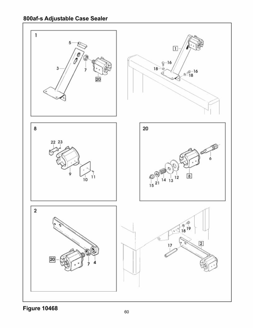
Figure 10468

61
Figure 10468
Ref. No. 3M Part No. Description
10468-1 78-8134-2133-2 Tape Drum Bracket Assy, Top
10468-2 78-8134-1934-4 Tape Drum Bracket Assy, Bottom
10468-3 78-8134-2334-6 Bracket - Tape Drum, Upper
10468-4 78-8134-1936-9 Bracket - Tape Drum, Lower
10468-5 78-8070-1568-6 Cap - Bracket
10468-6 78-8134-1937-7 Shaft - Tape Drum
10468-7 78-8134-1938-5 Nut - M18x1
10468-8 78-8134-2335-3 Tape Drum Assy - 2" wide
10468-9 78-8134-2336-1 Tape Drum
10468-10 78-8134-2337-9 Leaf Spring
10468-11 78-8070-8337-0 Screw - Self Tapping, 7SPx8
10468-12 78-8060-8172-1 Washer - Friction
10468-13 78-8134-1939-3 Washer - Tape Drum
10468-14 78-8134-1940-1 Spring - Tape Drum
10468-15 78-8060-8201-8 Nut - Self Locking, M10x1
10468-16 78-8060-8295-0 Screw - Hex.Hd. M6x16
10468-17 78-8134-2128-2 Spacer - Bracket
10468-18 78-8060-8312-3 Washer -Flat, M6
10468-19 78-8060-8292-7 Screw - Hex.Hd, M6x12
10468-20 78-8134-1942-7 Tape Drum Assy - 2" wide
10468-21 78-8060-8315-6 Washer - Flat, M10
10468-22 78-8134-2338-7 Latch

62
800af-s Adjustable Case Sealer
Figure 10469

63
Figure 10469
Pos. Code Description
10469-1 78-8060-8156-4 AccuGlide SST, Upper, 2 Inch – Taping Head 18900 Type 18900
10469-3 78-8134-2325-4 Spacer
Note – See Section II of this manual for taping head parts.
64
800af Adjustable Case Sealer
Figure 10470

65
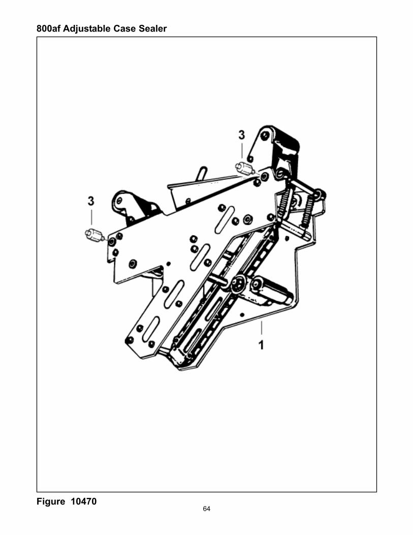
Figure 10470
Pos. Code Description
10470-1 78-8060-8157-2 AccuGlide SST, 2 Inch Upper Taping Head Type 18900
10470-3 78-8134-2324-7 Spacer
Note – See Section II of this manual for taping head parts.

66
800af-s Adjustable Case Sealer
Figure 10471/1 of 4

67
Figure 10471 (Page 1 of 4)
Ref. No. 3M Part No. Description
10471-1 78-8134-2134-0 Bed - Conveyor
10471-4 78-8060-8480-8 Pad -Foot
10471-5 78-8134-1994-8 Screw - Hex.Hd, M8x30
10471-6 78-8060-8320-6 Nut - Self Locking, M8
10471-8 78-8060-8481-6 Label - Height
10471-9 78-8060-8196-0 Clamp - Outer
10471-10 78-8060-8195-2 Clamp - Inner
10471-11 78-8060-8332-1 Screw - Soc.Hd, M8x16
10471-12 78-8134-2135-7 Center Frame - Right
10471-13 78-8134-2136-5 Center Frame - Left
10471-14 78-8060-8307-3 Screw - Soc.Hd, M8x20
10471-15 788060-8308-1 Washer - Flat, M8
10471-16 78-8134-2138-1 Spacer L=144
10471-18 78-8060-8295-0 Screw - Hex.Hd. M6x16
10471-19 78-8060-8312-3 Washer - Flat, M6
10471-20 78-8134-2138-1 Bearing Support - Gate
10471-21 78-8134-2139-9 Gate Assy
10471-22 78-8134-2140-7 Spacer - Gate
10471-23 78-8134-2141-5 Washer - Special, Gate
10471-24 78-8134-2142-3 Support - Gate Cylinder
10471-25 78-8134-2143-1 Shaft - Cylinder, Gate
10471-26 78-8134-2050-8 Ring - 8 DIN 6799
10471-27 78-8076-4757-9 Bumper
68Figure 10471/2 of 4
800af-s Adjustable Case Sealer
69
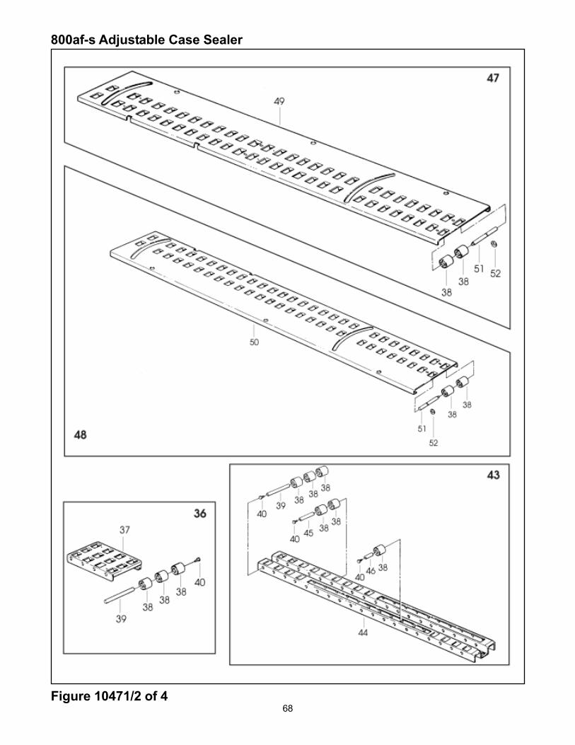
Figure 10471 (Page 2 of 4)
Ref. No. 3M Part No. Description
10471-32 78-8134-2145-6 Plate
10471-33 78-8060-8204-2 Screw - Hex.Hd, M6x12
10471-35 78-8060-8298-4 Screw - Soc.Hd, M6x12
10471-36 78-8134-2145-6 Conveyor Assy - Rear
10471-37 78-8134-2146-4 Cover - Rear
10471-38 78-8060-7693-7 Roller /32x38
10471-39 78-8060-8266-1 Shaft - /8x128
10471-40 78-8060-8300-8 Screw - Hex.Hd, M5x10
10471-41 78-8060-8306-5 Screw - Soc.Hd, M5x10
10471-42 78-8060-8303-2 Washer - Flat, M5
10471-43 78-8134-2147-2 Conveyor Assy - Center
10471-44 78-8134-2148-0 Conveyor - Center
10471-45 78-8134-2149-8 Shaft - /8x83
10471-46 78-8134-2150-6 Shaft - /8x43
10471-47 78-8134-2151-4 Conveyor Assy - Right
10471-48 78-8134-2152-2 Conveyor Assy - Left
10471-49 78-8134-2153-0 Conveyor - Right
10471-50 78-8134-2154-8 Conveyor - Left
10471-51 78-8134-2155-5 Shaft - Roller
10471-52 78-8100-0791-0 Ring - 7 DIN 6799
10471-53 78-8134-2156-3 Screw - Flat Hd, M5x10
10471-54 78-8060-8292-7 Screw - Hex.Hd, M6x12
10471-55 78-8134-2157-1 Support Assy W/Cam - Gate
10471-56 78-8134-2158-9 Support Assy - Gate
10471-57 78-8134-2087-0 Screw - Soc.Hd, M4x35

70Figure 10471/3 of 4
800af-s Adjustable Case Sealer
71
Figure 10471 (Page 3 of 4)
Ref. No. 3M Part No. Description
10471-58 78-8134-2088-8 Spacer - Valve Holder
10471-59 78-8134-2089-6 Plate
10471-60 78-8134-2084-7 Pin - Spring Holder
10471-61 78-8134-2085-4 Nut - Self Locking, M5
10471-62 78-8134-2086-2 Spring
10471-63 78-8055-0746-0 Link - Front Actuator
10471-64 78-8055-0747-8 Link - Rear Actuator
10471-65 78-8134-2090-4 Screw - Self Tapping, 8Px13
10471-66 78-8134-2159-7 Spacer - /8x26,5
10471-67 78-8134-2160-5 Support Assy - Cam
10471-68 78-8076-4776-9 Cam - Long
10471-69 78-8076-4777-7 Cam - Short
10471-70 78-8134-1985-6 Screw - Soc.Hd, M5x30
10471-71 78-8060-8290-1 Screw - Soc.Hd, M6x25
10471-72 78-8134-1979-9 Screw - Soc.Hd, M5x16
10471-73 78-8134-2161-3 Actuator Assy
10471-74 78-8134-2162-1 Support - Actuator
10471-75 78-8060-8321-4 Nut - Self Locking, M4
10471-76 78-8060-8297-6 Washer - Flat, M4
10471-77 78-8134-2163-9 Guide - Right, Actuator
10471-78 78-8134-2164-7 Guide - Left, Actuator
10471-79 78-8076-4782-7 Actuator - Flap Folder
10471-80 78-8134-2165-4 Plate - Actuator
10471-81 78-8134-2166-2 Screw - Soc.Hd, M6x35
10471-82 78-8134-2167-0 Screw - Soc.Hd, M5x70
10471-83 78-8134-2168-8 Screw - Soc.Hd, M5x35
10471-85 78-8076-4702-5 Grommet - Heyco SB1093-12
10471-86 78-8134-1999-7 Cover - Switch
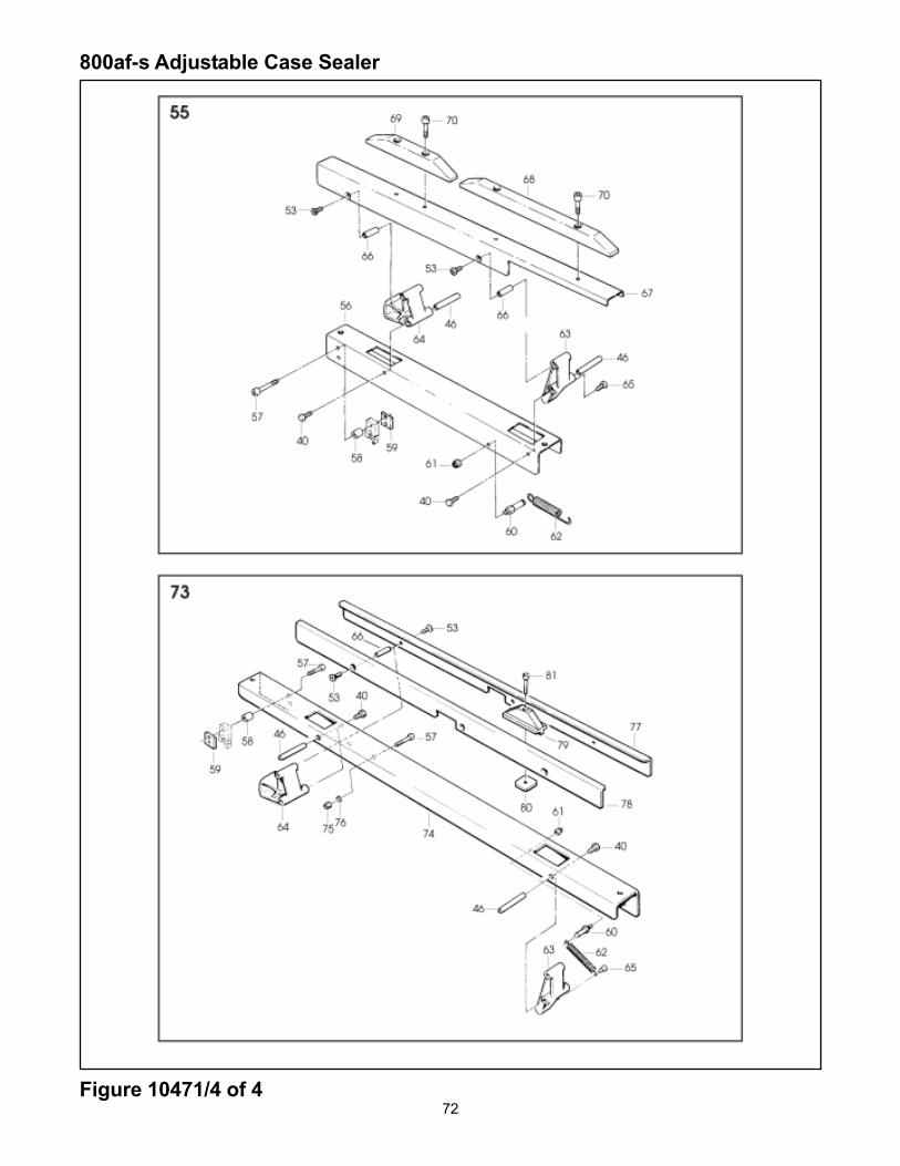
72Figure 10471/4 of 4
800af-s Adjustable Case Sealer

73
Figure 10471 (Page 4 of 4)
Ref. No. 3M Part No. Description
10471-87 78-8134-2000-3 Screw - M5x1010471-88 78-8060-8293-5 Nut - M510471-89 78-8060-7876-8 Cover - Plug, Lateral10471-90 78-8134-2169-6 Screw - Self Tapping, 6Px9,510471-91 78-8060-7873-5 Plug - Female10471-92 78-8060-7877-6 Plug - Housing, Vertical10471-93 78-8060-7591-3 Plug - Male10471-94 78-8076-4532-6 Cord Grip10471-95 78-8134-1974-0 Screw - Hex.Hd, M5x2010471-96 78-8060-8401-4 Washer - Special, Gate10471-97 78-8134-2170-4 Screw - Self Tapping, 6Px3010471-98 78-8060-7758-8 Fairlead /2010471-99 78-8134-2171-2 Caster Assy /10010471-100 78-8134-2172-0 Caster /10010471-101 78-8060-8405-5 Spacer - Caster10471-102 78-8060-8406-3 Washer - Special, Gate10471-103 78-8060-8304-0 Washer - Flat, M1210471-104 78-8060-8407-1 Nut - Self Locking, M1210471-105 78-8134-2173-8 Support Assy - Tape Roll10471-106 78-8134-2174-6 Support - Tape Roll Bracket10471-107 78-8134-2175-3 Shaft - Roller10471-109 78-8076-5030-0 Roller - Knurled, L=114 mm10471-110 78-8134-2176-1 Shaft - Roller10471-111 78-8076-5032-6 Roller - Knurled L=110,5 mm10471-112 78-8134-2177-9 Bracket Assy10471-113 78-8134-2178-7 Bracket10471-114 78-8114-4718-0 Shaft10471-115 78-8114-4719-8 Roller10471-116 78-8060-8203-4 Ring - Retaining 10 DIN 679910471-117 78-8060-7592-1 Socket10471-118 78-8134-1992-2 Leg Assy - Inner10471-119 78-8134-1993-0 Leg - Inner10471-120 78-8134-1995-5 Stop - Leg10471-121 78-8134-2009-4 Screw - Special, M5x1610471-122 78-8134-2179-5 Spacer10471-123 78-8134-2180-3 Plate - L/H10471-124 78-8134-2014-4 Shaft - Valve10471-125 78-8060-8296-8 Washer - Triple, M610471-126 78-8060-8318-0 Nut - Self Locking, M610471-127 78-8076-4536-7 Cap10471-128 78-8060-7875-0 Plug - Male
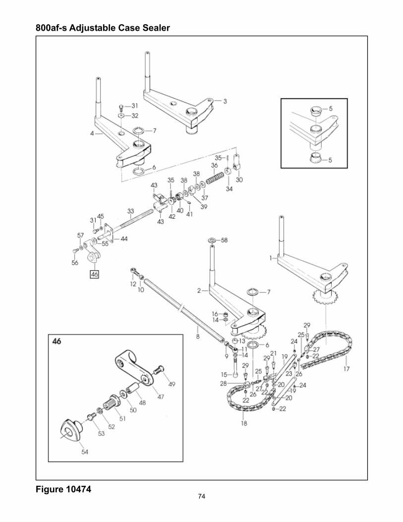
74Figure 10474
800af-s Adjustable Case Sealer

75
Figure 10474
Ref. No. 3M Part No. Description
10474-1 78-8134-2233-0 Arm Assy - Front, R/H10474-2 78-8134-2234-8 Arm Assy - Front, L/H10474-3 78-8134-2235-5 Arm Assy - Rear, R/H10474-4 78-8134-2236-3 Arm Assy - Rear, L/H10474-5 78-8076-4791-8 Bushing10474-6 78-8060-7534-3 Washer - Nylon10474-7 78-8134-2237-1 Ring - Lock10474-8 78-8134-2238-9 Bar - Coupling10474-9 78-8134-2239-7 Nut - Right, M1010474-10 78-8134-2240-5 Nut - Left, M1010474-11 78-8134-2241-3 Joint - Ball, KA-10-D10474-12 78-8134-2242-1 Joint - Ball, KAL-10-D10474-13 78-8134-2243-9 Spacer10474-14 78-8060-8315-6 Washer - Flat, M1010474-15 78-8134-2244-7 Screw - Soc.Hd, M10x8010474-16 78-8060-8328-9 Nut - Self Locking, M1010474-17 78-8134-2245-4 Chain, 3/8", 59 pitch10474-18 78-8134-2246-2 Chain - 3/8", 47 pitch10474-19 78-8134-2053-2 Link - Chain10474-20 78-8134-2058-1 Washer - Special, /3-10x310474-21 78-8134-2057-3 Screw - Special, M3x2510474-22 78-8134-2012-8 Nut - Self Locking, M310474-23 78-8134-2059-9 Block - Chain10474-24 78-8134-2060-7 E-Ring10474-25 78-8134-2061-5 Rod - Chain10474-26 78-8060-8288-5 Nut - M610474-27 78-8134-2055-7 Connector - Chain, L/H10474-28 78-8134-2054-0 Connector - Chain, R/H10474-29 78-8134-2056-5 Screw - Special, M3x2010474-30 78-8134-2247-0 Nut - Arm10474-31 78-8134-2030-0 Screw - Special, Hex.Hd, M6x1610474-32 78-8134-2248-8 Washer - Special, Gate10474-33 78-8134-2249-6 Screw - Centering10474-34 78-8134-2250-4 Bushing - Dowel10474-35 78-8060-8343-8 Pin10474-36 78-8134-2251-2 Washer - Belleville10474-37 78-8134-2252-0 Washer - Special10474-38 78-8060-8036-8 Washer - Nylon10474-39 78-8060-8436-0 Nut - Plastic10474-40 78-8134-2253-8 Ring - Nut10474-41 78-8134-2254-6 Set Screw - M5x810474-42 78-8134-2255-3 Bushing - Threaded10474-43 78-8134-2256-1 Plate W/Bushing10474-44 78-8134-2257-9 Plate10474-45 78-8060-8312-3 Washer -Flat, M610474-46 78-81341923-7 Crank Assy10474-47 78-8076-5422-9 Crank10474-48 78-8134-1924-5 Shaft - Crank10474-49 78-8060-8327-1 Screw - Flat Hd, M5x1610474-50 78-8070-1510-8 Washer - Nylon10474-51 78-8134-1925-2 Bushing10474-52 78-8060-8297-6 Washer - Flat, M410474-53 78-8100-0905-6 Screw - Hex.Hd, M4x1010474-54 78-8070-1512-4 Knob10474-55 78-8070-1548-8 Washer - Nylon10474-56 78-8060-8295-0 Screw - Hex.Hd, M6x1610474-57 78-8134-1926-0 Washer - Crank10474-58 78-8134-2258-7 Washer

76
800af-s Adjust able Case Sealer
Figure 10472/1of 2
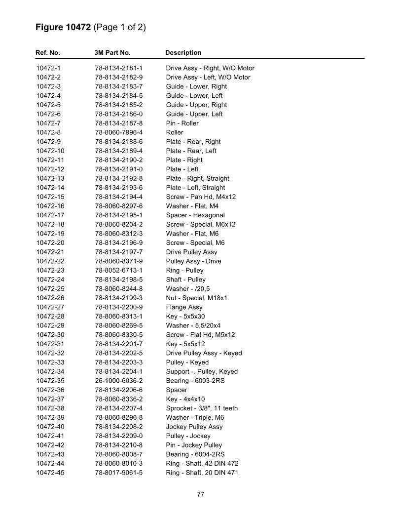
77
Figure 10472 (Page 1 of 2)
Ref. No. 3M Part No. Description
10472-1 78-8134-2181-1 Drive Assy - Right, W/O Motor10472-2 78-8134-2182-9 Drive Assy - Left, W/O Motor10472-3 78-8134-2183-7 Guide - Lower, Right10472-4 78-8134-2184-5 Guide - Lower, Left10472-5 78-8134-2185-2 Guide - Upper, Right10472-6 78-8134-2186-0 Guide - Upper, Left10472-7 78-8134-2187-8 Pin - Roller10472-8 78-8060-7996-4 Roller10472-9 78-8134-2188-6 Plate - Rear, Right10472-10 78-8134-2189-4 Plate - Rear, Left10472-11 78-8134-2190-2 Plate - Right10472-12 78-8134-2191-0 Plate - Left10472-13 78-8134-2192-8 Plate - Right, Straight10472-14 78-8134-2193-6 Plate - Left, Straight10472-15 78-8134-2194-4 Screw - Pan Hd, M4x1210472-16 78-8060-8297-6 Washer - Flat, M410472-17 78-8134-2195-1 Spacer - Hexagonal10472-18 78-8060-8204-2 Screw - Special, M6x1210472-19 78-8060-8312-3 Washer - Flat, M610472-20 78-8134-2196-9 Screw - Special, M610472-21 78-8134-2197-7 Drive Pulley Assy10472-22 78-8060-8371-9 Pulley Assy - Drive10472-23 78-8052-6713-1 Ring - Pulley10472-24 78-8134-2198-5 Shaft - Pulley10472-25 78-8060-8244-8 Washer - /20,510472-26 78-8134-2199-3 Nut - Special, M18x110472-27 78-8134-2200-9 Flange Assy10472-28 78-8060-8313-1 Key - 5x5x3010472-29 78-8060-8269-5 Washer - 5,5/20x410472-30 78-8060-8330-5 Screw - Flat Hd, M5x1210472-31 78-8134-2201-7 Key - 5x5x1210472-32 78-8134-2202-5 Drive Pulley Assy - Keyed10472-33 78-8134-2203-3 Pulley - Keyed10472-34 78-8134-2204-1 Support -. Pulley, Keyed10472-35 26-1000-6036-2 Bearing - 6003-2RS10472-36 78-8134-2206-6 Spacer10472-37 78-8060-8336-2 Key - 4x4x1010472-38 78-8134-2207-4 Sprocket - 3/8", 11 teeth10472-39 78-8060-8296-8 Washer - Triple, M610472-40 78-8134-2208-2 Jockey Pulley Assy10472-41 78-8134-2209-0 Pulley - Jockey10472-42 78-8134-2210-8 Pin - Jockey Pulley10472-43 78-8060-8008-7 Bearing - 6004-2RS10472-44 78-8060-8010-3 Ring - Shaft, 42 DIN 47210472-45 78-8017-9061-5 Ring - Shaft, 20 DIN 471
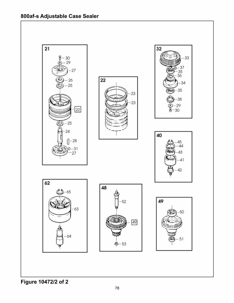
78
800af-s Adjustable Case Sealer
Figure 10472/2 of 2

79
Figure 10472 (Page 2 of 2)
Ref. No. 3M Part No. Description
10472-46 78-8060-8335-4 Washer - Triple, M810472-47 78-8060-8320-6 Nut - Self Locking, M810472-48 78-8134-2212-4 Wrap Pulley Assy10472-49 78-8076-5106-8 Idler Pulley Assy10472-50 78-8023-2544-5 Bearing - 6203-2RS10472-51 78-8023-2410-9 Bearing - 6000-2RS10472-52 78-8134-2213-2 Shaft - Wrap Pulley10472-53 78-8060-8314-9 Ring - 10 DIN 47110472-54 78-8060-8295-0 Screw - Hex.Hd, M6x1610472-55 78-8060-8013-7 Belt - Timing, 210L07510472-56 78-8094-6050-0 Spacer - Motor10472-57 78-8134-2214-0 Washer - Motor10472-58 78-8060-8333-9 Screw - Flat Hd, M5x2010472-59 78-8134-2215-7 Pulley - 17XL05010472-60 78-8060-8326-3 Set Screw - M5x610472-61 78-8060-8016-0 Belt - Timing, 190XL05010472-62 78-8134-2216-5 Idler Roller Assy10472-63 78-8052-6710-7 Roller - Idler10472-64 78-8134-2217-3 Shaft - Roller10472-65 78-8134-2218-1 Ring - Shaft, 25 DIN 47110472-66 78-8076-4865-0 Belt - Box Drive10472-67 78-8134-2219-9 Tensioning - Belt10472-68 78-8060-8308-1 Washer - Flat, M810472-69 78-8060-8315-6 Washer - Flat, M1010472-70 78-8060-8328-9 Nut - Self Locking, M1010472-71 78-8060-8289-3 Nut - M810472-72 78-8134-2220-7 Block - Belt10472-73 78-8060-8311-5 Screw - Soc.Hd, M6x2010472-74 78-8134-2221-5 Screw - Belt Adjustment10472-75 78-8134-2222-3 Cover - Drive, Right10472-76 78-8134-2223-1 Cover - Drive, Left10472-77 78-8060-8337-0 Screw - Self Tapping, 7SPx810472-80 78-8134-2090-4 Screw - Self Tapping, 8Px1310472-81 78-8134-2224-9 Sprocket - 3/8", 28 teeth10472-82 78-8134-2225-6 Tab Washer10472-83 78-8134-2226-4 Washer - Centering10472-84 78-8134-2227-2 Chain - 3/8" Pitch L=5010472-85 78-8076-5258-7 Cover - Chain10472-86 78-8060-8306-5 Screw - Soc.Hd, M5x1010472-87 78-8134-2228-0 Spacer - Drive10472-88 78-8060-8299-2 Screw - Flat Hd, M6x1610472-89 78-8060-8243-0 Washer - Special10472-90 78-8134-2229-8 Guard - Belt

80
800af-s Adjustable Case Sealer
Figure 10476
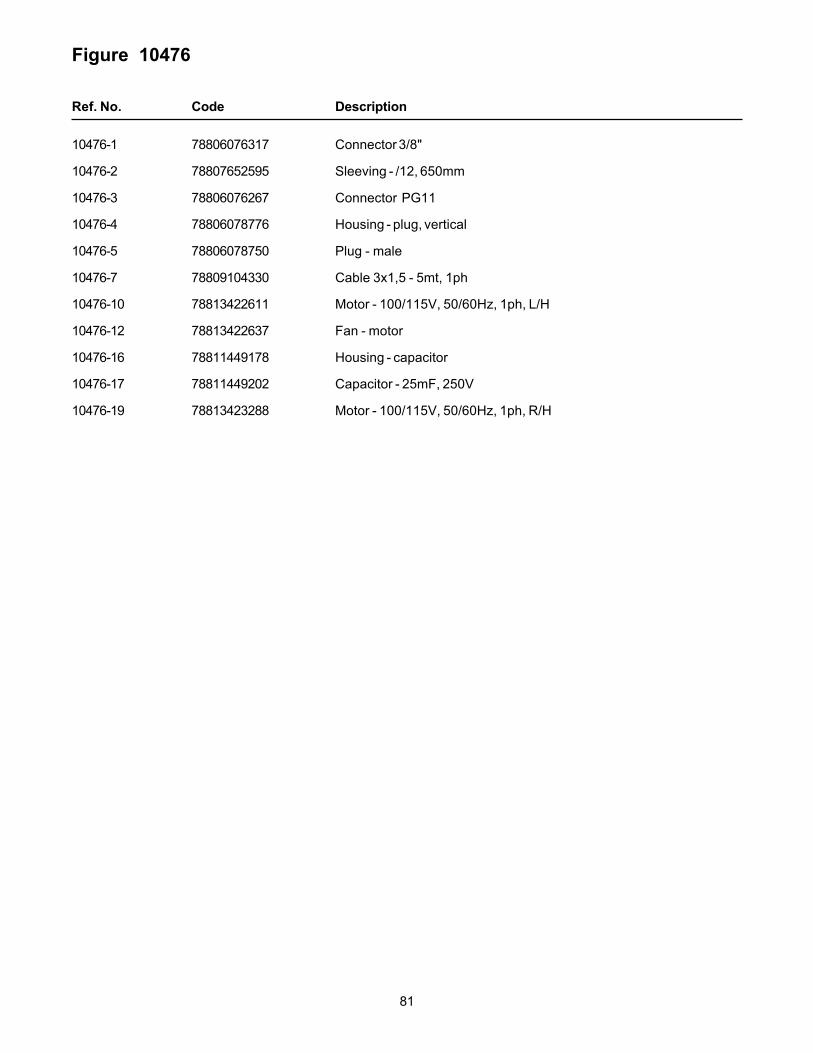
81
Figure 10476
Ref. No. Code Description
10476-1 78806076317 Connector 3/8"
10476-2 78807652595 Sleeving - /12, 650mm
10476-3 78806076267 Connector PG11
10476-4 78806078776 Housing - plug, vertical
10476-5 78806078750 Plug - male
10476-7 78809104330 Cable 3x1,5 - 5mt, 1ph
10476-10 78813422611 Motor - 100/115V, 50/60Hz, 1ph, L/H
10476-12 78813422637 Fan - motor
10476-16 78811449178 Housing - capacitor
10476-17 78811449202 Capacitor - 25mF, 250V
10476-19 78813423288 Motor - 100/115V, 50/60Hz, 1ph, R/H
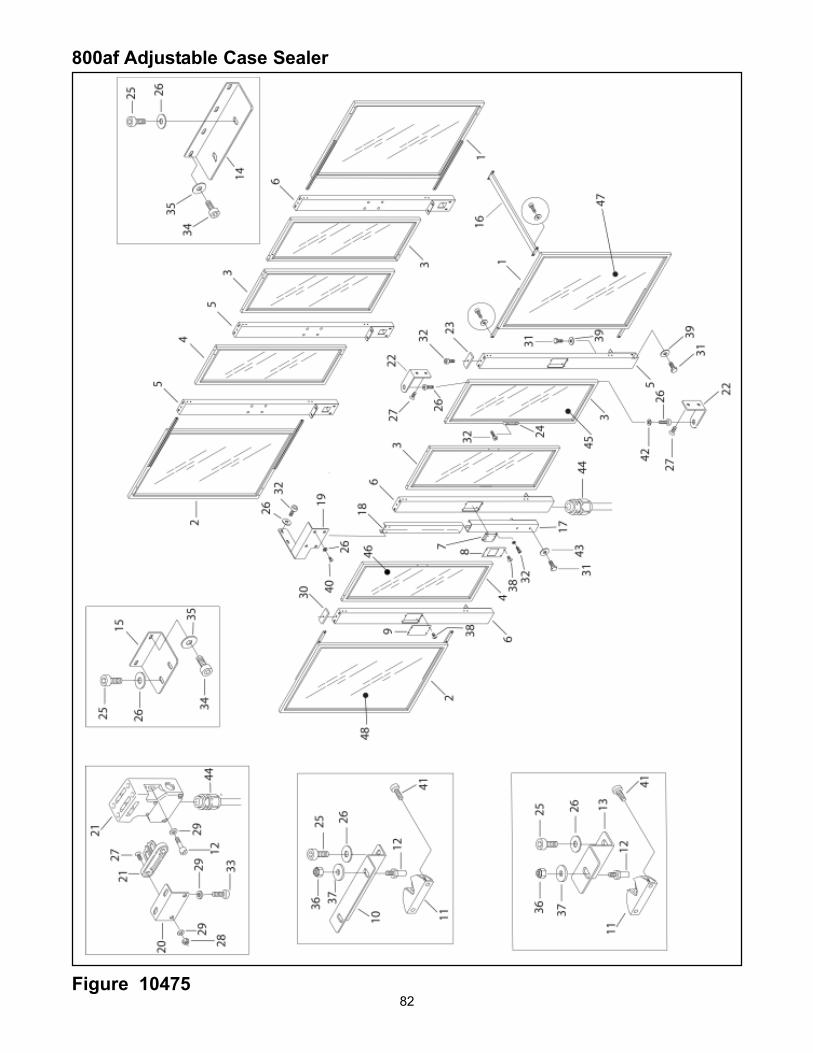
82
800af Adjustable Case Sealer
Figure 10475

83
Figure 10475 (Page 1 of 2)
Ref. No. 3M Part No. Description
10475-1 78-8134-2296-7 Panel Assembly - Infeed
10475-2 78-8134-2297-5 Panel Assembly - Outfeed
10475-3 78-8134-2298-5 Panel Assembly - Front
10475-4 78-8134-2299-1 Panel Assembly – Rear
10475-5 78-8134-2300-7 Jamb - Left
10475-6 78-8134-2301-5 Jamb – Right
10475-7 78-8134-2302-3 Support - E Stop
10475-8 78-8134-2303-1 Cover
10475-9 78-8134-2304-9 Cover
10475-10 78-8134-2305-6 Bracket
10475-11 78-8134-2306-4 Stop - Door
10475-12 78-8134-2083-9 Screw - Soc.hd, M5x20
10475-13 78-8134-2307-2 Bracket - Rear
10475-14 78-8134-2308-0 Bracket - Front
10475-15 26-8134-2309-8 Bracket - Rear Panel
10475-16 26-8134-2310-6 Cross Bar
10475-17 78-8134-2311-4 Jamb
10475-18 78-8134-2312-2 Guard
10475-19 78-8134-2313-0 Bracket - Guard
10475-20 78-8134-2314-8 Bracket - Switch
10475-21 26-8076-4929-4 Security Switch
10475-22 78-8134-2315-5 Hinge
10475-23 78-8076-4512-8 Cap - Left
10475-24 78-8134-2316-3 Handle
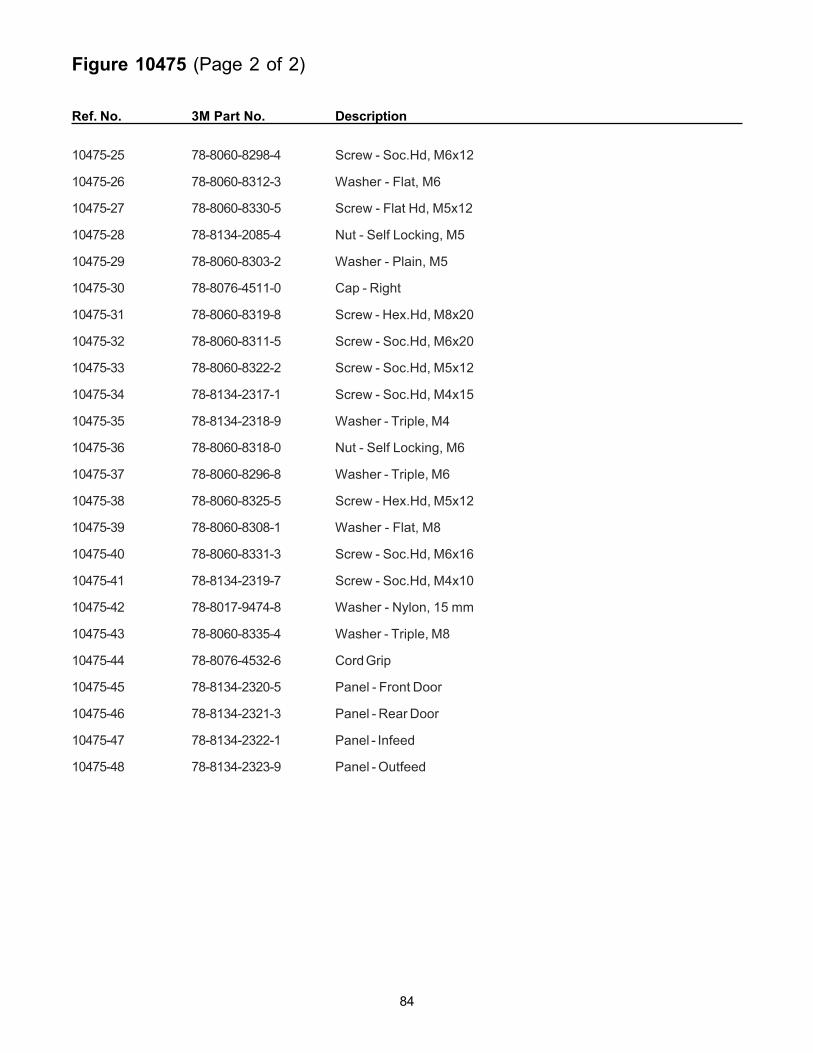
84
Figure 10475 (Page 2 of 2)
Ref. No. 3M Part No. Description
10475-25 78-8060-8298-4 Screw - Soc.Hd, M6x12
10475-26 78-8060-8312-3 Washer - Flat, M6
10475-27 78-8060-8330-5 Screw - Flat Hd, M5x12
10475-28 78-8134-2085-4 Nut - Self Locking, M5
10475-29 78-8060-8303-2 Washer - Plain, M5
10475-30 78-8076-4511-0 Cap - Right
10475-31 78-8060-8319-8 Screw - Hex.Hd, M8x20
10475-32 78-8060-8311-5 Screw - Soc.Hd, M6x20
10475-33 78-8060-8322-2 Screw - Soc.Hd, M5x12
10475-34 78-8134-2317-1 Screw - Soc.Hd, M4x15
10475-35 78-8134-2318-9 Washer - Triple, M4
10475-36 78-8060-8318-0 Nut - Self Locking, M6
10475-37 78-8060-8296-8 Washer - Triple, M6
10475-38 78-8060-8325-5 Screw - Hex.Hd, M5x12
10475-39 78-8060-8308-1 Washer - Flat, M8
10475-40 78-8060-8331-3 Screw - Soc.Hd, M6x16
10475-41 78-8134-2319-7 Screw - Soc.Hd, M4x10
10475-42 78-8017-9474-8 Washer - Nylon, 15 mm
10475-43 78-8060-8335-4 Washer - Triple, M8
10475-44 78-8076-4532-6 Cord Grip
10475-45 78-8134-2320-5 Panel - Front Door
10475-46 78-8134-2321-3 Panel - Rear Door
10475-47 78-8134-2322-1 Panel - Infeed
10475-48 78-8134-2323-9 Panel - Outfeed

THIS PAGE IS BLANK
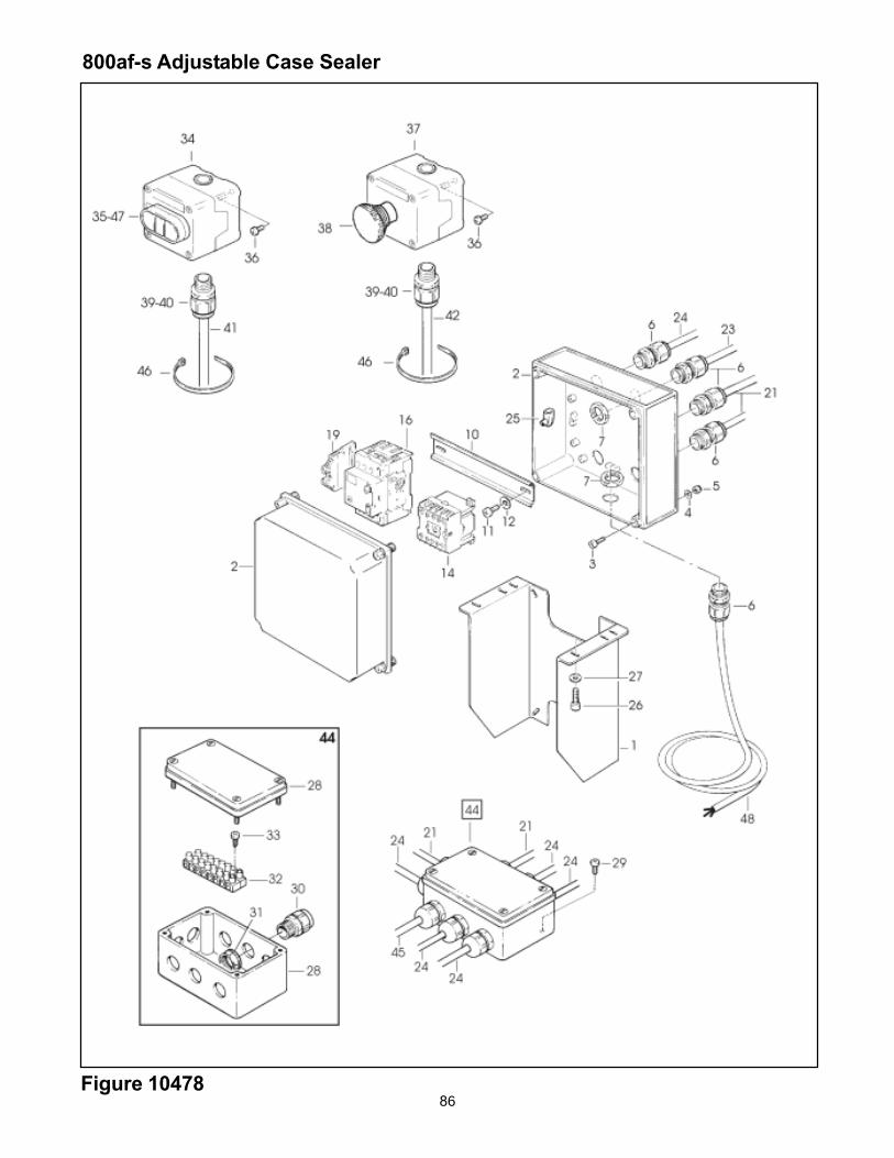
86
800af-s Adjustable Case Sealer
Figure 10478

87
Figure 10478
Ref. No. 3M Part No. Description
10478-1 78-8134-2001-1 Support - Electric Box10478-2 78-8113-6759-4 Electric Box10478-3 78-8134-2291-8 Screw - Soc.Hd, M4x2010478-4 78-8060-8297-6 Washer - Flat, M410478-5 78-8060-8321-4 Nut - M410478-6 78-8076-4715-7 Cord Grip10478-7 78-8076-5211-6 Set Nut10478-10 78-8094-6382-7 Guide - Mounting10478-11 78-8028-8208-0 Screw - Self Tapping, 6Px9,510478-12 78-8017-9018-5 Washer - Triple, M410478-14 78-8094-6383-5 Contactor - Allen Bradley 10E 110V 60Hz10478-16 78-8076-5378-3 Switch - 1.6-2.5 A.10478-19 78-8114-4890-7 Clamp10478-21 78-8091-0433-0 Cable - 3x1.5, 1ph, 5mt10478-23 78-8076-5176-1 Cable - 3x0.75, 5mt10478-24 78-8076-5273-6 Cable - 3x1, 5mt10478-25 78-8076-4602-7 Terminal10478-26 78-8060-8331-3 Screw - Soc.Hd, M6x1610478-27 78-8060-8312-3 Washer - Flat, M610478-28 78-8076-4881-7 Pull Box10478-29 78-8134-2000-3 Screw - M5x1010478-30 78-8076-4532-6 Cord Grip10478-31 78-8076-4645-6 Lock Nut10478-32 78-8076-4968-2 Terminal10478-33 78-8134-2292-6 Screw - Self Tapping, 4.2x1910478-34 78-8134-2293-4 Support - ON/OFF10478-35 78-8094-6386-8 Switch - ON/OFF10478-36 78-8100-0907-2 Screw - Pan, M4x1610478-37 78-8134-2293-4 Support - E-Stop10478-38 26-1014-5845-8 E-stop - /40 W/Latch+Contact10478-39 78-8060-8327-1 Screw - Flat Hd, M5x1610478-40 78-8060-8401-4 Washer - Special, M510478-41 78-8060-8303-2 Washer - Flat, M510478-42 78-8060-8293-5 Nut - M510478-44 78-8076-5275-1 Pull Box Assy - 1ph10478-45 78-8100-0832-2 Wire - 3x1, 5mt10478-46 78-8060-8029-3 Clamp10478-47 78-8134-2340-3 Cover - On/off switch10478-48 78-8028-7909-4 Power Cord – U.S.A.
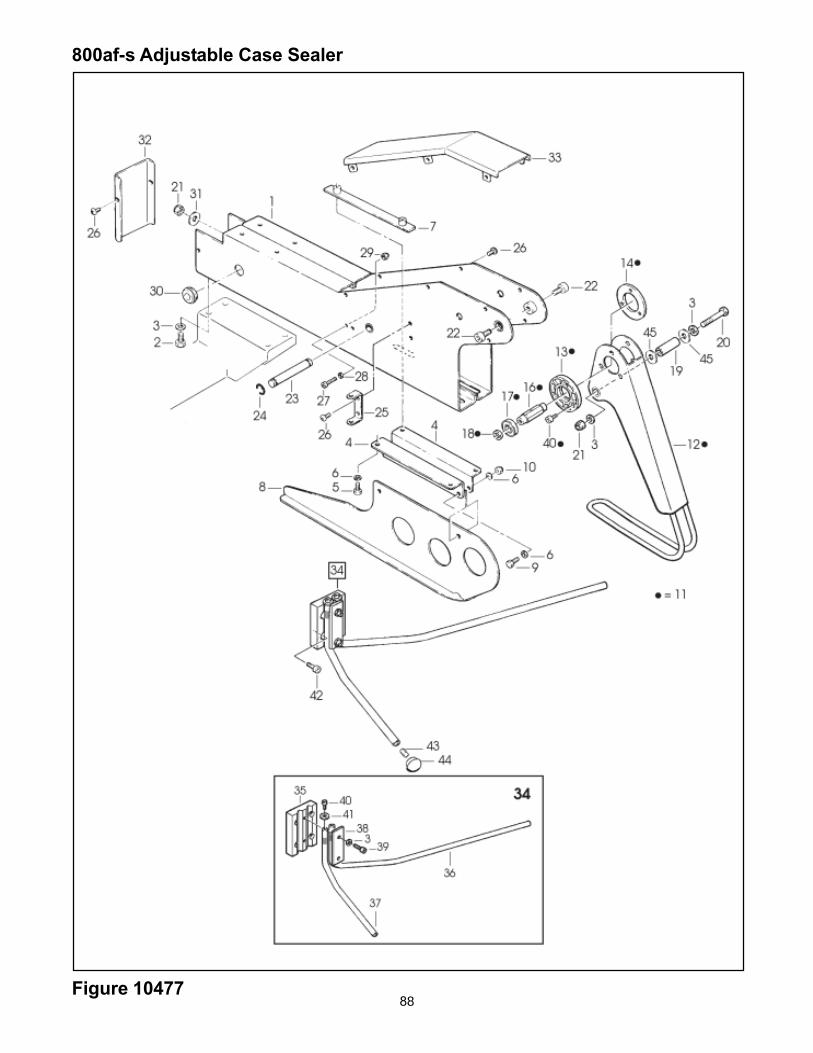
88Figure 10477
800af-s Adjustable Case Sealer

89
Figure 10477
Ref. No. 3M Part No. Description
10477-1 78-8134-2266-0 Support - Front Flap Folder10477-2 78-8060-8302-4 Screw - Hex.Hd, M8x2510477-3 78-8060-8308-1 Washer - Flat, M810477-4 78-8134-2267-8 Plate - Box Guide10477-5 78-8060-8311-5 Screw - Soc.Hd, M6x2010477-6 78-8060-8312-3 Washer - Fat, M610477-7 78-8134-2268-6 Strap10477-8 78-8134-2269-4 Flap Folder - Front10477-9 78-8060-8295-0 Screw - Hex.Hd, M6x1610477-10 78-8060-8318-0 Nut - Self Locking, M610477-11 78-8134-2270-2 Flap Folder Assy - Rear10477-12 78-8134-2271-0 Flap Folder - Rear10477-13 78-8134-2272-8 Support - Bearing10477-14 78-8134-2273-6 Washer - Support10477-16 78-8134-2274-4 Shaft - Support10477-17 78-8134-2106-8 Bearing - 6002-2S10477-18 78-8134-2275-1 Spacer - Bearing10477-19 78-8134-2276-9 Spacer - Cylinder10477-20 78-8134-2277-7 Screw - Hex.Hd, M8x6010477-21 78-8060-8320-6 Nut - Self Locking, M810477-22 78-8060-8307-3 Screw - Soc.Hd, M8x2010477-23 78-8134-2278-5 Pin - Air Cylinder10477-24 78-8134-2279-3 Ring - 8 DIN 679910477-25 78-8134-2280-1 Holder10477-26 78-8134-2000-3 Screw - M5x1010477-27 78-8134-2087-0 Screw - Soc. Hd, M4x3510477-28 78-8060-8297-6 Washer - Flat, M410477-29 78-8060-8321-4 Nut - Self Locking, M410477-30 78-8060-7785-1 Fairlead /2210477-31 78-8060-8335-4 Washer - Triple, M810477-32 78-8134-2281-9 Cover - Fap Folder Support10477-33 78-8134-2282-7 Cover10477-34 78-8134-2283-5 Flap Folder Assy - Side10477-35 78-8134-2284-3 Block - Side Flap Folder10477-36 78-8134-2285-0 Side Flap Folder - R/H10477-37 78-8134-2286-8 Side Flap Folder - L/H10477-38 78-8134-2287-6 Plate - Side Flap Folder10477-39 78-8134-2288-4 Screw - Soc.Hd, M8x3510477-40 78-8060-8298-4 Screw - Soc.Hd, M6x1210477-41 78-8060-8296-8 Washer - Triple, M610477-42 78-8134-2289-2 Screw - Soc.Hd, M8x2510477-43 78-8134-2290-0 Set Screw - M6x2010477-44 78-8060-7862-8 Knob Assy10477-45 78-8060-8304-0 Washer - Flat, M12

THIS PAGE IS BLANK