Embed Size (px)
Citation preview
1DECGP04 Printed in USA
READ THROUGH THE PRELIMINARY INFORMATION BEFORE YOU START BUILDING. IT CONTAINS IMPORTANT INSTRUCTIONS, WARNINGS, AND INFORMATION CONCERNING THE BUILDING AND USE OF THIS MODEL.
© 2011 Hobbico®, Inc V:2.0
Instruction Manual
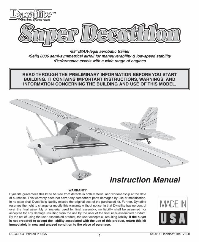
•89” IMAA-legal aerobatic trainer•Selig 8036 semi-symmetrical airfoil for maneuverability & low-speed stability
•Performance excels with a wide range of engines
WARRANTYDynaflite guarantees this kit to be free from defects in both material and workmanship at the date of purchase. This warranty does not cover any component parts damaged by use or modification. In no case shall Dynaflite’s liability exceed the original cost of the purchased kit. Further, Dynaflite reserves the right to change or modify this warranty without notice. In that Dynaflite has no control over the final assembly or material used for final assembly, no liability shall be assumed nor accepted for any damage resulting from the use by the user of the final user-assembled product. By the act of using the user-assembled product, the user accepts all resulting liability. If the buyer is not prepared to accept the liability associated with the use of this product, return this kit immediately in new and unused condition to the place of purchase.
™
2
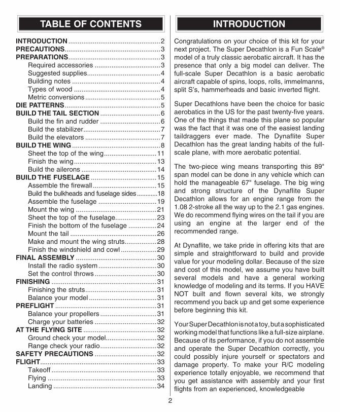
TABLE OF CONTENTS
INTRODUCTION .................................................2PRECAUTIONS ...................................................3PREPARATIONS .................................................3 Required accessories ...................................3 Suggested supplies .......................................4 Building notes ...............................................4 Types of wood ..............................................4 Metric conversions ........................................5DIE PATTERNS ...................................................5BUILD THE TAIL SECTION ................................6 Build the fin and rudder ................................6 Build the stabilizer .........................................7 Build the elevators ........................................7BUILD THE WING ...............................................8 Sheet the top of the wing ............................11 Finish the wing ............................................13 Build the ailerons ........................................14BUILD THE FUSELAGE ...................................15 Assemble the firewall ..................................15 Build the bulkheads and fuselage sides ............18 Assemble the fuselage ...............................19 Mount the wing ...........................................21 Sheet the top of the fuselage ......................23 Finish the bottom of the fuselage ...............24 Mount the tail ..............................................26 Make and mount the wing struts .................28 Finish the windshield and cowl ...................29FINAL ASSEMBLY ...........................................30 Install the radio system ...............................30 Set the control throws .................................30FINISHING ........................................................31 Finishing the struts ......................................31 Balance your model ....................................31PREFLIGHT ......................................................31 Balance your propellers ..............................31 Charge your batteries .................................32AT THE FLYING SITE .......................................32 Ground check your model ...........................32 Range check your radio ..............................32SAFETY PRECAUTIONS .................................32FLIGHT ..............................................................33 Takeoff ........................................................33 Flying ..........................................................33 Landing .......................................................34
INTRODUCTION
Congratulations on your choice of this kit for your next project. The Super Decathlon is a Fun Scale® model of a truly classic aerobatic aircraft. It has the presence that only a big model can deliver. The full-scale Super Decathlon is a basic aerobatic aircraft capable of spins, loops, rolls, immelmanns, split S’s, hammerheads and basic inverted flight.
Super Decathlons have been the choice for basic aerobatics in the US for the past twenty-five years. One of the things that made this plane so popular was the fact that it was one of the easiest landing taildraggers ever made. The Dynaflite Super Decathlon has the great landing habits of the full-scale plane, with more aerobatic potential.
The two-piece wing means transporting this 89" span model can be done in any vehicle which can hold the manageable 67" fuselage. The big wing and strong structure of the Dynaflite Super Decathlon allows for an engine range from the 1.08 2-stroke all the way up to the 2.1 gas engines. We do recommend flying wires on the tail if you are using an engine at the larger end of the recommended range.
At Dynaflite, we take pride in offering kits that are simple and straightforward to build and provide value for your modeling dollar. Because of the size and cost of this model, we assume you have built several models and have a general working knowledge of modeling and its terms. If you HAVE NOT built and flown several kits, we strongly recommend you back up and get some experience before beginning this kit.
Your Super Decathlon is not a toy, but a sophisticated working model that functions like a full-size airplane. Because of its performance, if you do not assemble and operate the Super Decathlon correctly, you could possibly injure yourself or spectators and damage property. To make your R/C modeling experience totally enjoyable, we recommend that you get assistance with assembly and your first flights from an experienced, knowledgeable
33
modeler. Your local hobby shop has information about flying clubs in your area whose membership includes qualified instructors if needed.
If you are not already a member of the AMA, please join! The AMA is the governing body of model aviation and membership provides liability insurance coverage, protects modelers’ rights and interests and is required to fly at most R/C sites.
Academy of Model Aeronautics 5151 East Memorial Drive
Muncie, IN 47302-9252Tele. (800) 435-9262Fax (765) 741-0057
Or via the Internet at:http://www.modelaircraft.org
IMPORTANT!!!Two of the most important things you can do to preserve the radio controlled aircraft hobby are to avoid flying near full-scale aircraft and avoid flying near or over groups of people.
PRECAUTIONS
1. You must assemble the plane according to the instructions. Do not alter or modify the model, as doing so may result in an unsafe or unflyable model. In a few cases the instructions may differ slightly from the photos or plan. In those instances, follow the written instructions.
2. You must take the time to build straight, true and strong.
3. You must install all R/C and other components so that the model operates properly on the ground and in the air.
4. You must test the operation of the model before the first and each successive flight to insure that all equipment operates correctly. You must also make certain that the model has remained structurally sound.
Please inventory and inspect all parts carefully before starting to build! If any parts are missing, broken or defective or if you have any questions about building or flying this model, please call us
at: (217) 398-8970 or you may email us at [email protected] and we'll be glad to help. If you are calling for replacement parts, please look up the part numbers and have them ready when calling.
PREPARATIONS
REQUIRED ITEMS
These are the items not included with your kit; you will need to purchase them separately. Items in parentheses (GPMQ4131) are suggested part numbers recognized by distributors and hobby shops and are listed for your ordering convenience. GPM is the Great Planes® brand, TOP is the Top Flite® brand and HCA is the Hobbico® brand.
❏ 4+ Channel radio w/6 servos (5 high torque) ❏ 2 18" Servo extension wires (ailerons) ❏ 2 “Y” Connectors (ailerons, elevators) ❏ Engine: 1.20 - 1.60 4-stroke,
1.08 - 1.8 2-stroke, or 1.5 - 2.1 gas ❏ Engine mount and mounting hardware ❏ 16 - 24 oz. Fuel tank ❏ Standard fuel tubing, glow (GPMQ4131) ❏ Tygon fuel tubing, gas (DUBQ0427) ❏ Gas stopper (DUBQ0675) ❏ 2 3-1/4" Main wheels (GPMQ4226) ❏ 1 1-1/2" Tail wheel (GPMQ4243) ❏ 4 5/32" Wheel collars (GPMQ4306) ❏ 2 1/8" Wheel collars (GPMQ4304) ❏ 2 3/16" Axles (GPMQ4278) ❏ 20 Giant Scale hinges ❏ 4 8-32 x 1" Socket head bolts (GPMQ3048) ❏ 4 8-32 Blind Nuts (GPMQ3328) ❏ Coverite™ Fabric or other covering
(approximately 5 rolls) ❏ Paint for fuelproofing, engine cowl and
windows ❏ 1/4" Latex Foam Rubber (HCAQ1000) ❏ 3" Spinner (GPMQ4530) ❏ 1 or 2 1/4 Scale pilot(s) (optional)
(DGAQ2110) ❏ Decathlon cockpit kit (optional) (DYFQ8115)
4
SUGGESTED SUPPLIES
We recommend Great Planes Pro™ CA and Epoxy
❏ 4 oz. Thin CA Adhesive (GPMR5904) ❏ 4 oz. Medium CA+ Adhesive (GPMR5910) ❏ 2 oz. Thick CA- Adhesive (GPMR6015) ❏ Pro CA Applicator Tips (HCAR3780) ❏ Pro CA Accelerator w/pump (HCAR3750) ❏ 6-Minute Epoxy (GPMR6045) ❏ 30-Minute Epoxy (GPMR6047) ❏ 8 oz. Aliphatic Resin Wood Glue
(GPMR6163) ❏ 4 oz. Milled Fiberglass (GPMR6165) ❏ Microballoon Filler (TOPR1090) ❏ J&Z Products RC/56 Canopy Glue (JOZR5007) ❏ Great Planes Plan Protector (GPMR6167)
BUILDING NOTES
• When you see the term “cut and fit” in the instructions, it means you should first position the part on the assembly without using any glue. Slightly modify or shape the part as necessary for the best fit. Do not glue unless instructed to do so.
• Throughout the assembly of this model, thin CA should be used unless the step calls for another type of adhesive. If your parts do not fit well, substitute medium or thick CA.
• Whenever just “epoxy” is called for, you may use either 30-minute epoxy or 6-minute epoxy. When 30-minute epoxy is specified, it is highly recommended that you use only 30-minute epoxy because you will need either the working time or the additional strength.
• CA accelerator causes CA glues to react immediately, but residual accelerator can prematurely cure CA on nearby joints even hours later.
• During construction you will be using a number of balsa sticks to frame various assemblies. Ample material is included but you should study the plans, then make an effort to cut the longest pieces you will need first. Label the pieces for later
reference as you cut them. By doing this now, you won't have to splice pieces together later.
• Do not throw away any leftover material until after you have completed your model. Some small pieces of leftover balsa or plywood are used during construction.
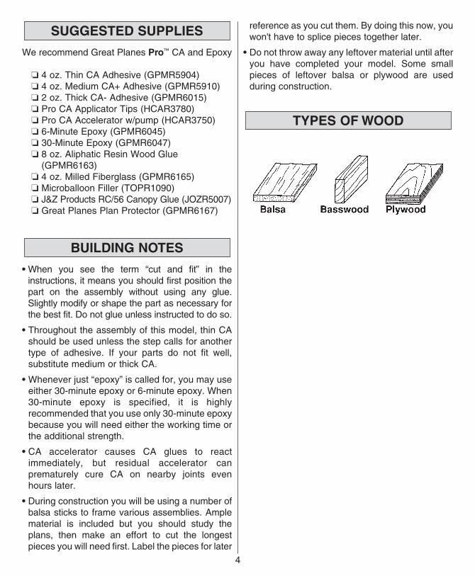
TYPES OF WOOD
55
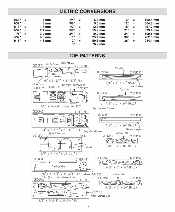
1/64" = .4 mm 1/32" = .8 mm 1/16" = 1.6 mm 3/32" = 2.4 mm 1/8" = 3.2 mm 5/32" = 4.0 mm 3/16" = 4.8 mm
1/4" = 6.4 mm 3/8" = 9.5 mm 1/2" = 12.7 mm 5/8" = 15.9 mm 3/4" = 19.0 mm 1" = 25.4 mm 2" = 50.8 mm 3" = 76.2 mm
6" = 152.4 mm 12" = 304.8 mm 18" = 457.2 mm 21" = 533.4 mm 24" = 609.6 mm 30" = 762.0 mm 36" = 914.4 mm
DIE PATTERNS
METRIC CONVERSIONS
BUILD THE TAIL SECTION
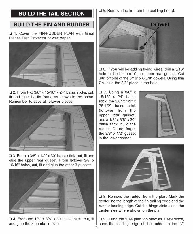
BUILD THE FIN AND RUDDER
❏ 1. Cover the FIN/RUDDER PLAN with Great Planes Plan Protector or wax paper.
❏ 2. From two 3/8" x 15/16" x 24" balsa sticks, cut, fit and glue the fin frame as shown in the photo. Remember to save all leftover pieces.
❏ 3. From a 3/8" x 1/2" x 30" balsa stick, cut, fit and glue the upper rear gusset. From leftover 3/8" x 15/16" balsa, cut, fit and glue the other 3 gussets.
❏ 4. From the 1/8" x 3/8" x 30" balsa stick, cut, fit and glue the 3 fin ribs in place.
❏ 5. Remove the fin from the building board.
❏ 6. If you will be adding flying wires, drill a 5/16" hole in the bottom of the upper rear gusset. Cut 3/8" off one of the 5/16" x 6-5/8" dowels. Using thin CA, glue the 3/8" piece in the hole.
❏ 7. Using a 3/8" x 15/16" x 24" balsa stick, the 3/8" x 1/2" x 28-1/2" balsa stick (leftover from the upper rear gusset) and a 1/8" x 3/8" x 30" balsa stick, build the rudder. Do not forget the 3/8" x 1/2" gusset in the lower corner.
❏ 8. Remove the rudder from the plan. Mark the centerline the length of the fin trailing edge and the rudder leading edge. Cut the hinge slots along the centerlines where shown on the plan.
❏ 9. Using the fuse plan top view as a reference, sand the leading edge of the rudder to the “V”
6
77
shape shown. Make sure the “V” is large enough to allow for the specified left and right movement of the rudder (see “SET THE CONTROL THROWS”, page 30).
❏ 10. Round the leading edge of the fin and the top and trailing edge of the rudder. Note: Check the plans to see the location of the dorsal fin and do not sand the leading edge of the fin in that area.
BUILD THE STABILIZER
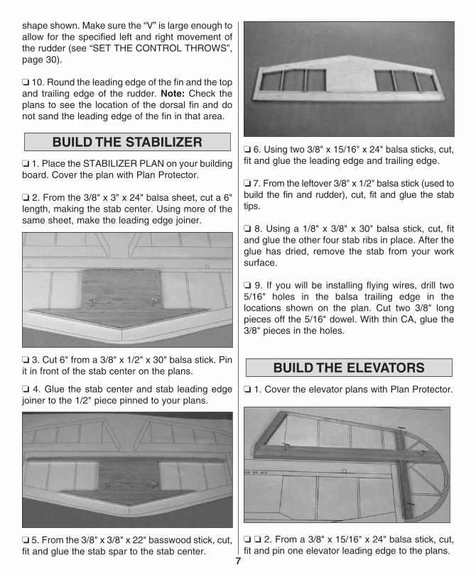
❏ 1. Place the STABILIZER PLAN on your building board. Cover the plan with Plan Protector.
❏ 2. From the 3/8" x 3" x 24" balsa sheet, cut a 6" length, making the stab center. Using more of the same sheet, make the leading edge joiner.
❏ 3. Cut 6" from a 3/8" x 1/2" x 30" balsa stick. Pin it in front of the stab center on the plans.
❏ 4. Glue the stab center and stab leading edge joiner to the 1/2" piece pinned to your plans.
❏ 5. From the 3/8" x 3/8" x 22" basswood stick, cut, fit and glue the stab spar to the stab center.
❏ 6. Using two 3/8" x 15/16" x 24" balsa sticks, cut, fit and glue the leading edge and trailing edge.
❏ 7. From the leftover 3/8" x 1/2" balsa stick (used to build the fin and rudder), cut, fit and glue the stab tips.
❏ 8. Using a 1/8" x 3/8" x 30" balsa stick, cut, fit and glue the other four stab ribs in place. After the glue has dried, remove the stab from your work surface.
❏ 9. If you will be installing flying wires, drill two 5/16" holes in the balsa trailing edge in the locations shown on the plan. Cut two 3/8" long pieces off the 5/16" dowel. With thin CA, glue the 3/8" pieces in the holes.
BUILD THE ELEVATORS
❏ 1. Cover the elevator plans with Plan Protector.
❏ ❏ 2. From a 3/8" x 15/16" x 24" balsa stick, cut, fit and pin one elevator leading edge to the plans.
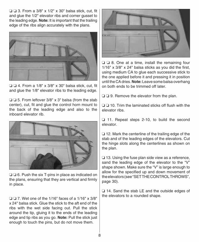
❏ ❏ 3. From a 3/8" x 1/2" x 30" balsa stick, cut, fit and glue the 1/2" elevator ribs and corner gusset to the leading edge. Note: It is important that the trailing edge of the ribs align accurately with the plans.
❏ ❏ 4. From a 1/8" x 3/8" x 30" balsa stick, cut, fit and glue the 1/8" elevator ribs to the leading edge.
❏ ❏ 5. From leftover 3/8" x 3" balsa (from the stab center), cut, fit and glue the control horn mount to the back of the leading edge and also to the inboard elevator rib.
❏ ❏ 6. Push the six T-pins in place as indicated on the plans, ensuring that they are vertical and firmly in place.
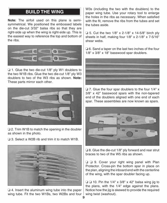
❏ ❏ 7. Wet one of the 1/16" faces of a 1/16" x 3/8" x 24" balsa stick. Glue the stick to the aft end of the ribs with the wet side facing out. Pull the stick around the tip, gluing it to the ends of the leading edge and tip ribs as you go. Note: Pull the stick just enough to touch the pins, but do not move them.
❏ ❏ 8. One at a time, install the remaining four 1/16" x 3/8" x 24" balsa sticks as you did the first, using medium CA to glue each successive stick to the one applied before it and pressing it in position until the CA dries. Note: Leave some balsa overhang on both ends to be trimmed off later.
❏ ❏ 9. Remove the elevator from the plan.
❏ ❏ 10. Trim the laminated sticks off flush with the elevator ribs.
❏ 11. Repeat steps 2-10, to build the second elevator.
❏ 12. Mark the centerline of the trailing edge of the stab and of the leading edges of the elevators. Cut the hinge slots along the centerlines as shown on the plan.
❏ 13. Using the fuse plan side view as a reference, sand the leading edge of the elevator to the “V” shape shown. Make sure the “V” is large enough to allow for the specified up and down movement of the elevators (see “SET THE CONTROL THROWS”, page 30).
❏ 14. Sand the stab LE and the outside edges of the elevators to a rounded shape.
8
9
BUILD THE WING
Note: The airfoil used on this plane is semi-symmetrical. We positioned the embossed labels on the die-cut 3/32" balsa ribs so that they are right-side up when the wing is right-side up. This is the easiest way to reference the top and bottom of the ribs.
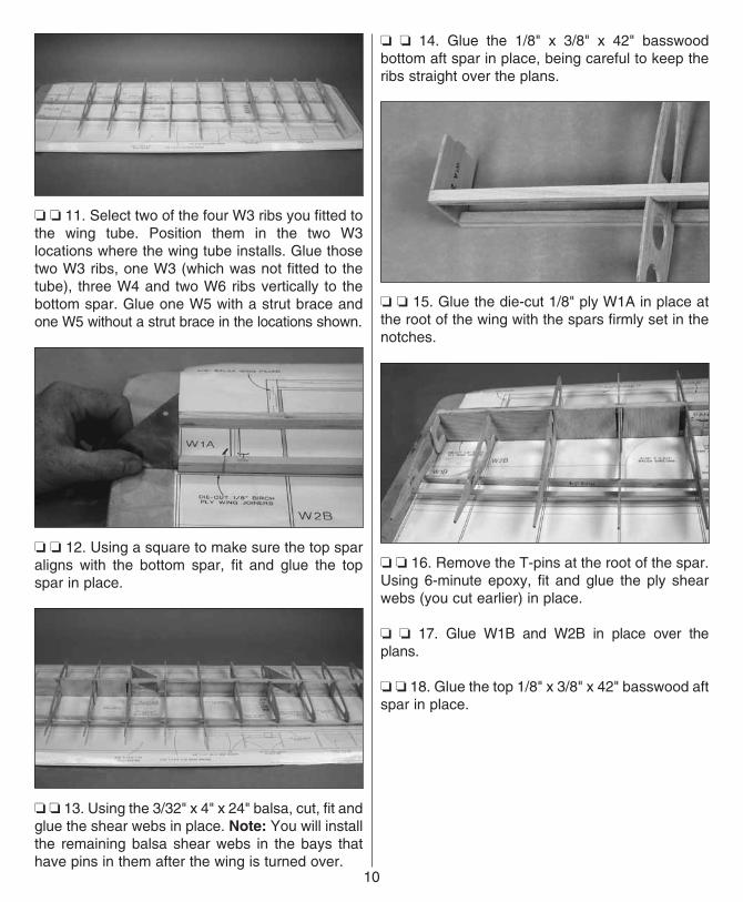
❏ 1. Glue the two die-cut 1/8" ply W1 doublers to the two W1B ribs. Glue the two die-cut 1/8" ply W3 doublers to two of the W3 ribs as shown. Note: These parts mirror each other.
❏ 2. Trim W1B to match the opening in the doubler as shown in the photo.
❏ 3. Select a W2B rib and trim it to match W1B.
❏ 4. Insert the aluminum wing tube into the paper wing tube. Fit the two W1Bs, two W2Bs and four
W3s (including the two with the doublers) to the paper wing tube. Use your rotary tool to enlarge the holes in the ribs as necessary. When satisfied with the fit, remove the ribs from the tubes and set the tubes aside.
❏ 5. Cut the two 1/8" x 2-1/8" x 14-5/8" birch ply sheets in half, making four 1/8" x 2-1/8" x 7-5/16" shear webs.
❏ 6. Sand a taper on the last two inches of the four 1/8" x 3/8" x 18" basswood spar doublers.
❏ 7. Glue the four spar doublers to the four 1/4" x 3/8" x 42" basswood spars with the non-tapered end of the doublers aligned with one end of each spar. These assemblies are now known as spars.
❏ 8. Glue the die-cut 1/8" ply forward and rear strut braces to two of the W5 ribs as shown.
❏ ❏ 9. Cover your right wing panel with Plan Protector. Cross-pin the bottom spar in place on the plan, aligning the inboard end with the centerline of the wing, with the spar doubler facing up.
❏ ❏ 10. Pin the 1/4" x 3/8" x 42" balsa wing jig to the plans, with the 1/4" edge against the plans. Notice how the jig is skewed to provide the required wing twist (washout).
9
❏ ❏ 11. Select two of the four W3 ribs you fitted to the wing tube. Position them in the two W3 locations where the wing tube installs. Glue those two W3 ribs, one W3 (which was not fitted to the tube), three W4 and two W6 ribs vertically to the bottom spar. Glue one W5 with a strut brace and one W5 without a strut brace in the locations shown.
❏ ❏ 12. Using a square to make sure the top spar aligns with the bottom spar, fit and glue the top spar in place.
❏ ❏ 13. Using the 3/32" x 4" x 24" balsa, cut, fit and glue the shear webs in place. Note: You will install the remaining balsa shear webs in the bays that have pins in them after the wing is turned over.
❏ ❏ 14. Glue the 1/8" x 3/8" x 42" basswood bottom aft spar in place, being careful to keep the ribs straight over the plans.
❏ ❏ 15. Glue the die-cut 1/8" ply W1A in place at the root of the wing with the spars firmly set in the notches.
❏ ❏ 16. Remove the T-pins at the root of the spar. Using 6-minute epoxy, fit and glue the ply shear webs (you cut earlier) in place.
❏ ❏ 17. Glue W1B and W2B in place over the plans.
❏ ❏ 18. Glue the top 1/8" x 3/8" x 42" basswood aft spar in place.
10
11
❏ ❏ 19. Cut the paper wing tube in half. Insert the aluminum tube inside the paper tube. Using medium CA, glue the paper tube to the four ribs and the ply shear web, aligning the end with the root rib. Remove the aluminum tube from the paper tube.
❏ ❏ 20. Fit and glue the die-cut 1/8" ply tube plug in the outboard end of the paper tube.
❏ ❏ 21. Glue the die-cut 1/8" ply W2A rib in place.
❏ ❏ 22. Glue the die-cut 1/8" ply dowel plate (DP) in place.
❏ ❏ 23. Glue the 1/8" x 1" x 42" balsa sub leading edge to the ribs, centering it vertically on the front of the ribs.
❏ ❏ 24. Using a razor plane and/or sanding bar, shape the top of the sub leading edge to the contour of the ribs. Trim the sub leading edge flush with the wing tip rib and the root rib.
❏ ❏ 25. From a 1/4" x 1" x 24" balsa stick, fit and glue the trailing edge in place in the aileron bay. Sand the top to the shape of the ribs.
❏ ❏ 26. From a 3/8" x 3/4" x 24" balsa stick, cut and glue the four hinge doublers in place.
SHEET THE WING
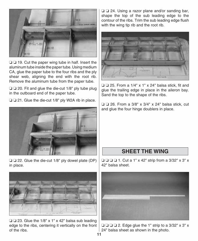
❏ ❏ ❏ ❏ 1. Cut a 1" x 42" strip from a 3/32" x 3" x 42" balsa sheet.
❏ ❏ ❏ ❏ 2. Edge glue the 1" strip to a 3/32" x 3" x 24" balsa sheet as shown in the photo.
11
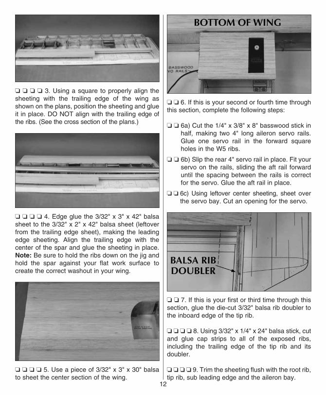
❏ ❏ ❏ ❏ 3. Using a square to properly align the sheeting with the trailing edge of the wing as shown on the plans, position the sheeting and glue it in place. DO NOT align with the trailing edge of the ribs. (See the cross section of the plans.)
❏ ❏ ❏ ❏ 4. Edge glue the 3/32" x 3" x 42" balsa sheet to the 3/32" x 2" x 42" balsa sheet (leftover from the trailing edge sheet), making the leading edge sheeting. Align the trailing edge with the center of the spar and glue the sheeting in place. Note: Be sure to hold the ribs down on the jig and hold the spar against your flat work surface to create the correct washout in your wing.
❏ ❏ ❏ ❏ 5. Use a piece of 3/32" x 3" x 30" balsa to sheet the center section of the wing.
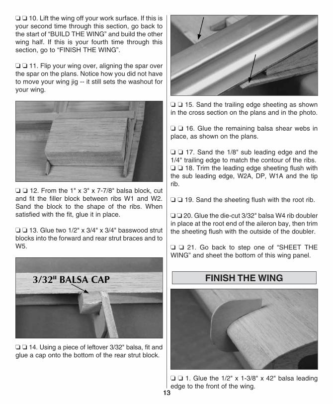
❏ ❏ 6. If this is your second or fourth time through this section, complete the following steps:
❏ ❏ 6a) Cut the 1/4" x 3/8" x 8" basswood stick in half, making two 4" long aileron servo rails. Glue one servo rail in the forward square holes in the W5 ribs.
❏ ❏ 6b) Slip the rear 4" servo rail in place. Fit your servo on the rails, sliding the aft rail forward until the spacing between the rails is correct for the servo. Glue the aft rail in place.
❏ ❏ 6c) Using leftover center sheeting, sheet over the servo bay. Cut an opening for the servo.
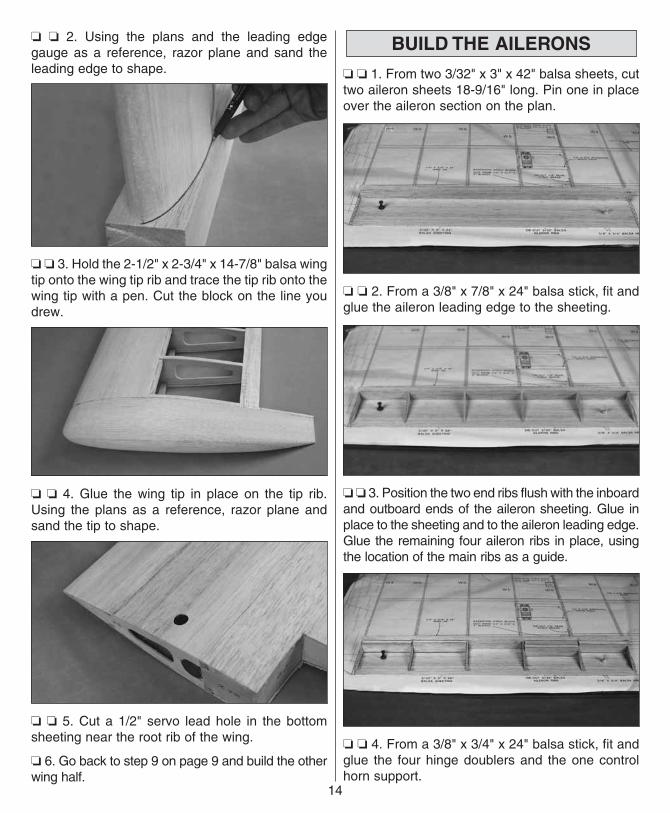
❏ ❏ 7. If this is your first or third time through this section, glue the die-cut 3/32" balsa rib doubler to the inboard edge of the tip rib.
❏ ❏ ❏ ❏ 8. Using 3/32" x 1/4" x 24" balsa stick, cut and glue cap strips to all of the exposed ribs, including the trailing edge of the tip rib and its doubler.
❏ ❏ ❏ ❏ 9. Trim the sheeting flush with the root rib, tip rib, sub leading edge and the aileron bay.
12
13
❏ ❏ 10. Lift the wing off your work surface. If this is your second time through this section, go back to the start of “BUILD THE WING” and build the other wing half. If this is your fourth time through this section, go to “FINISH THE WING”.
❏ ❏ 11. Flip your wing over, aligning the spar over the spar on the plans. Notice how you did not have to move your wing jig -- it still sets the washout for your wing.
❏ ❏ 12. From the 1" x 3" x 7-7/8" balsa block, cut and fit the filler block between ribs W1 and W2. Sand the block to the shape of the ribs. When satisfied with the fit, glue it in place.
❏ ❏ 13. Glue two 1/2" x 3/4" x 3/4" basswood strut blocks into the forward and rear strut braces and to W5.
❏ ❏ 14. Using a piece of leftover 3/32" balsa, fit and glue a cap onto the bottom of the rear strut block.
❏ ❏ 15. Sand the trailing edge sheeting as shown in the cross section on the plans and in the photo.
❏ ❏ 16. Glue the remaining balsa shear webs in place, as shown on the plans.
❏ ❏ 17. Sand the 1/8" sub leading edge and the 1/4" trailing edge to match the contour of the ribs.❏ ❏ 18. Trim the leading edge sheeting flush with the sub leading edge, W2A, DP, W1A and the tip rib.
❏ ❏ 19. Sand the sheeting flush with the root rib.
❏ ❏ 20. Glue the die-cut 3/32" balsa W4 rib doubler in place at the root end of the aileron bay, then trim the sheeting flush with the outside of the doubler.
❏ ❏ 21. Go back to step one of “SHEET THE WING” and sheet the bottom of this wing panel.
FINISH THE WING
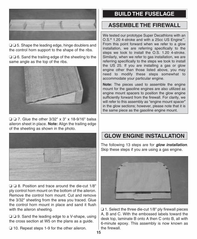
❏ ❏ 1. Glue the 1/2" x 1-3/8" x 42" balsa leading edge to the front of the wing.
13
❏ ❏ 2. Using the plans and the leading edge gauge as a reference, razor plane and sand the leading edge to shape.
❏ ❏ 3. Hold the 2-1/2" x 2-3/4" x 14-7/8" balsa wing tip onto the wing tip rib and trace the tip rib onto the wing tip with a pen. Cut the block on the line you drew.
❏ ❏ 4. Glue the wing tip in place on the tip rib. Using the plans as a reference, razor plane and sand the tip to shape.
❏ ❏ 5. Cut a 1/2" servo lead hole in the bottom sheeting near the root rib of the wing.
❏ 6. Go back to step 9 on page 9 and build the other wing half.
BUILD THE AILERONS
❏ ❏ 1. From two 3/32" x 3" x 42" balsa sheets, cut two aileron sheets 18-9/16" long. Pin one in place over the aileron section on the plan.
❏ ❏ 2. From a 3/8" x 7/8" x 24" balsa stick, fit and glue the aileron leading edge to the sheeting.
❏ ❏ 3. Position the two end ribs flush with the inboard and outboard ends of the aileron sheeting. Glue in place to the sheeting and to the aileron leading edge. Glue the remaining four aileron ribs in place, using the location of the main ribs as a guide.
❏ ❏ 4. From a 3/8" x 3/4" x 24" balsa stick, fit and glue the four hinge doublers and the one control horn support.
14
15
❏ ❏ 5. Shape the leading edge, hinge doublers and the control horn support to the shape of the ribs.
❏ ❏ 6. Sand the trailing edge of the sheeting to the same angle as the top of the ribs.
❏ ❏ 7. Glue the other 3/32" x 3" x 18-9/16" balsa aileron sheet in place. Note: Align the trailing edge of the sheeting as shown in the photo.
❏ ❏ 8. Position and trace around the die-cut 1/8" ply control horn mount on the bottom of the aileron. Remove the control horn mount. Cut and remove the 3/32" sheeting from the area you traced. Glue the control horn mount in place and sand it flush with the aileron sheeting.
❏ ❏ 9. Sand the leading edge to a V-shape, using the cross section at W5 on the plans as a guide.
❏ 10. Repeat steps 1-9 for the other aileron.
BUILD THE FUSELAGE
ASSEMBLE THE FIREWALL
We tested our prototype Super Decathlons with an O.S.® 1.20 4-stroke and with a 25cc US Engine™. From this point forward when we refer to a glow installation, we are referring specifically to the steps we took to install the O.S. 1.20 4-stroke. Similarly, when we refer to gas installation, we are referring specifically to the steps we took to install the US 25. If you are installing a gas or glow engine other than those listed above, you may need to modify these steps somewhat to accommodate your particular engine.
Note: The pieces used to assemble the engine mount for the gasoline engines are also utilized as engine mount spacers to position the glow engine sufficiently forward from the firewall. For clarity, we will refer to this assembly as “engine mount spacer” in the glow sections; however, please note that it is the same piece as the gasoline engine mount.
GLOW ENGINE INSTALLATION
The following 13 steps are for glow installation. Skip these steps if you are using a gas engine.
❏ 1. Select the three die-cut 1/8" ply firewall pieces A, B and C. With the embossed labels toward the desk top, laminate B onto A then C onto B, all with 6-minute epoxy. This assembly is now known as the firewall.
15
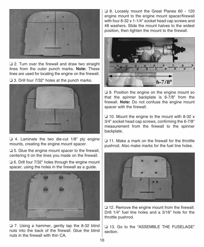
❏ 2. Turn over the firewall and draw two straight lines from the outer punch marks. Note: These lines are used for locating the engine on the firewall.
❏ 3. Drill four 7/32" holes at the punch marks.
❏ 4. Laminate the two die-cut 1/8" ply engine mounts, creating the engine mount spacer.
❏ 5. Glue the engine mount spacer to the firewall, centering it on the lines you made on the firewall.
❏ 6. Drill four 7/32" holes through the engine mount spacer, using the holes in the firewall as a guide.
❏ 7. Using a hammer, gently tap the 8-32 blind nuts into the back of the firewall. Glue the blind nuts in the firewall with thin CA.
❏ 8. Loosely mount the Great Planes 60 - 120 engine mount to the engine mount spacer/firewall with four 8-32 x 1-1/4" socket head cap screws and #8 washers. Slide the mount halves to the widest position, then tighten the mount to the firewall.
❏ 9. Position the engine on the engine mount so that the spinner backplate is 6-7/8" from the firewall. Note: Do not confuse the engine mount spacer with the firewall.
❏ 10. Mount the engine to the mount with 8-32 x 3/4" socket head cap screws, confirming the 6-7/8" measurement from the firewall to the spinner backplate.
❏ 11. Make a mark on the firewall for the throttle pushrod. Also make marks for the fuel line holes.
❏ 12. Remove the engine mount from the firewall. Drill 1/4" fuel line holes and a 3/16" hole for the throttle pushrod.
❏ 13. Go to the “ASSEMBLE THE FUSELAGE” section.
16
17
GAS ENGINE INSTALLATION
The following steps are for a gas engine installation. Skip these 10 steps if you are using a glow engine.
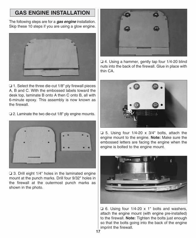
❏ 1. Select the three die-cut 1/8" ply firewall pieces A, B and C. With the embossed labels toward the desk top, laminate B onto A then C onto B, all with 6-minute epoxy. This assembly is now known as the firewall.
❏ 2. Laminate the two die-cut 1/8" ply engine mounts.
❏ 3. Drill eight 1/4" holes in the laminated engine mount at the punch marks. Drill four 9/32" holes in the firewall at the outermost punch marks as shown in the photo.
❏ 4. Using a hammer, gently tap four 1/4-20 blind nuts into the back of the firewall. Glue in place with thin CA.
❏ 5. Using four 1/4-20 x 3/4" bolts, attach the engine mount to the engine. Note: Make sure the embossed letters are facing the engine when the engine is bolted to the engine mount.
❏ 6. Using four 1/4-20 x 1" bolts and washers, attach the engine mount (with engine pre-installed) to the firewall. Note: Tighten the bolts just enough so that the bolts going into the back of the engine imprint the firewall.
17
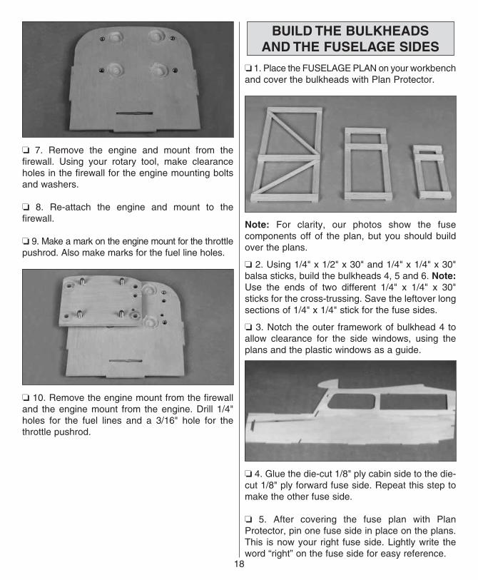
❏ 7. Remove the engine and mount from the firewall. Using your rotary tool, make clearance holes in the firewall for the engine mounting bolts and washers.
❏ 8. Re-attach the engine and mount to the firewall.
❏ 9. Make a mark on the engine mount for the throttle pushrod. Also make marks for the fuel line holes.
❏ 10. Remove the engine mount from the firewall and the engine mount from the engine. Drill 1/4" holes for the fuel lines and a 3/16" hole for the throttle pushrod.
BUILD THE BULKHEADSAND THE FUSELAGE SIDES
❏ 1. Place the FUSELAGE PLAN on your workbench and cover the bulkheads with Plan Protector.
Note: For clarity, our photos show the fuse components off of the plan, but you should build over the plans.
❏ 2. Using 1/4" x 1/2" x 30" and 1/4" x 1/4" x 30" balsa sticks, build the bulkheads 4, 5 and 6. Note: Use the ends of two different 1/4" x 1/4" x 30" sticks for the cross-trussing. Save the leftover long sections of 1/4" x 1/4" stick for the fuse sides.
❏ 3. Notch the outer framework of bulkhead 4 to allow clearance for the side windows, using the plans and the plastic windows as a guide.
❏ 4. Glue the die-cut 1/8" ply cabin side to the die-cut 1/8" ply forward fuse side. Repeat this step to make the other fuse side.
❏ 5. After covering the fuse plan with Plan Protector, pin one fuse side in place on the plans. This is now your right fuse side. Lightly write the word “right” on the fuse side for easy reference.
18
19
❏ 6. Glue the die-cut 1/8" balsa top longeron and die-cut 1/8" balsa bottom longeron to the fuse sides.
❏ 7. Glue the die-cut 1/8" ply rear fuse side to the top and bottom longerons.
❏ 8. Remove the pins from the fuse side and cover the fuse side with Plan Protector.
❏ 9. Align the second fuse side over the first and pin it in place. Glue the longerons and the rear fuse side in place, making the other fuse side assembly. These assemblies are now known as fuse sides. Note: It is very important that the fuse sides be the same. Take your time aligning these pieces so that the second fuse side matches the first.
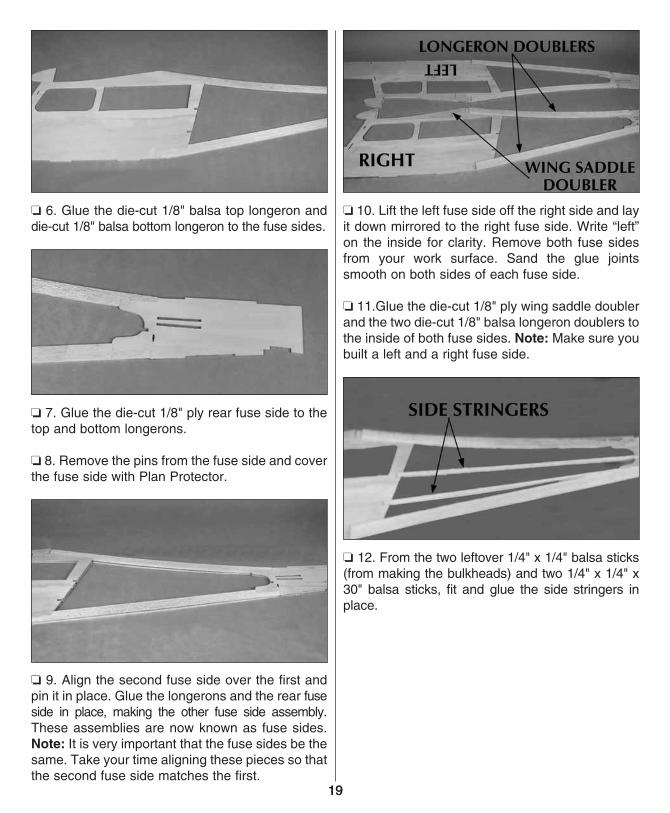
❏ 10. Lift the left fuse side off the right side and lay it down mirrored to the right fuse side. Write “left” on the inside for clarity. Remove both fuse sides from your work surface. Sand the glue joints smooth on both sides of each fuse side.
❏ 11.Glue the die-cut 1/8" ply wing saddle doubler and the two die-cut 1/8" balsa longeron doublers to the inside of both fuse sides. Note: Make sure you built a left and a right fuse side.
❏ 12. From the two leftover 1/4" x 1/4" balsa sticks (from making the bulkheads) and two 1/4" x 1/4" x 30" balsa sticks, fit and glue the side stringers in place.
19
ASSEMBLE THE FUSELAGE
❏ 1. Pin the die-cut 1/8" ply fuse bottom in place on the top view plans. Note: Make sure the slot in the front of the fuse bottom matches the plan. This slot helps set the right thrust.
❏ 2. Fit the fuse sides, bulkhead 3A and bulkhead 4 in place. Use a square to check that the fuse sides are perpendicular to your work surface at 3A. Glue 3A to the fuse sides and fuse bottom. Note: The top of bulkhead 3A has a slight taper towards the inside, so there should be a slight gap between your square and the fuse side at the top.
❏ 3. Glue bulkhead 4 to the sides and bottom, again making sure the fuse sides are perpendicular to your work bench.
❏ 4. Epoxy the firewall in place, again using your square to make sure the fuse sides are perpendicular to your work surface.
❏ 5. Glue the fuse bottom to the fuse sides.
❏ 6. Unpin the fuse bottom from your work surface.
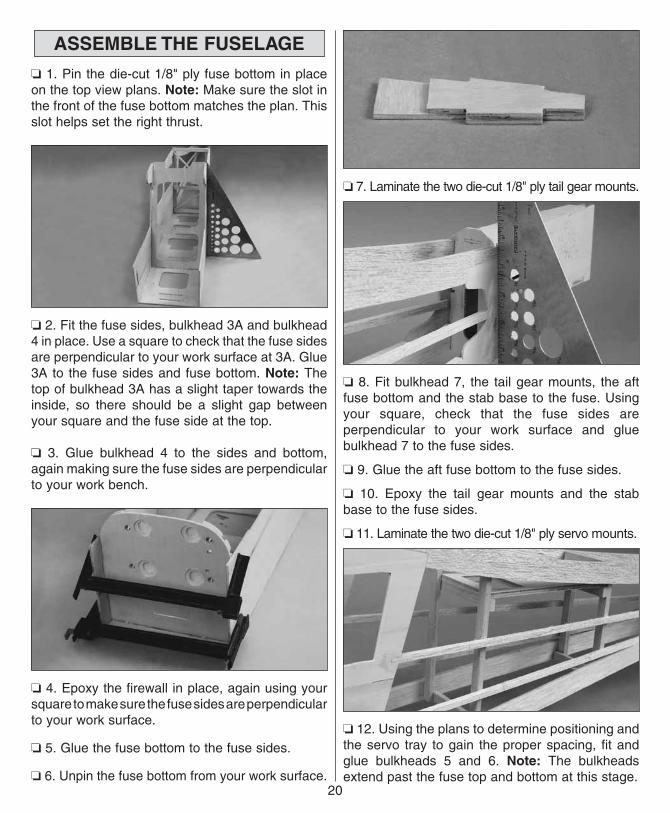
❏ 7. Laminate the two die-cut 1/8" ply tail gear mounts.
❏ 8. Fit bulkhead 7, the tail gear mounts, the aft fuse bottom and the stab base to the fuse. Using your square, check that the fuse sides are perpendicular to your work surface and glue bulkhead 7 to the fuse sides.
❏ 9. Glue the aft fuse bottom to the fuse sides.
❏ 10. Epoxy the tail gear mounts and the stab base to the fuse sides.
❏ 11. Laminate the two die-cut 1/8" ply servo mounts.
❏ 12. Using the plans to determine positioning and the servo tray to gain the proper spacing, fit and glue bulkheads 5 and 6. Note: The bulkheads extend past the fuse top and bottom at this stage.
20
21
❏ 13. Sand bulkheads 4, 5 and 6 flush with the top of the fuse.
❏ 14. Turn the fuse upside-down. Glue the servo tray to bulkheads 5 and 6.
❏ 15. Sand bulkheads 5 and 6 flush with the bottom of the fuse.
❏ 16. Fit the servo hatch in place, trimming as necessary. Note: The hatch is made oversize to allow for any deviations in building.
❏ 17. Mount the hatch to the fuse with four #2 x 3/8" flat head screws.
❏ 18. Using 3/32" x 3" x 30" balsa, sheet the bottom of the fuse with the grain running across the fuse bottom, NOT along the length of the fuse. Note: Be careful not to glue the hatch to the fuse. Save the leftover sheeting for the front deck.
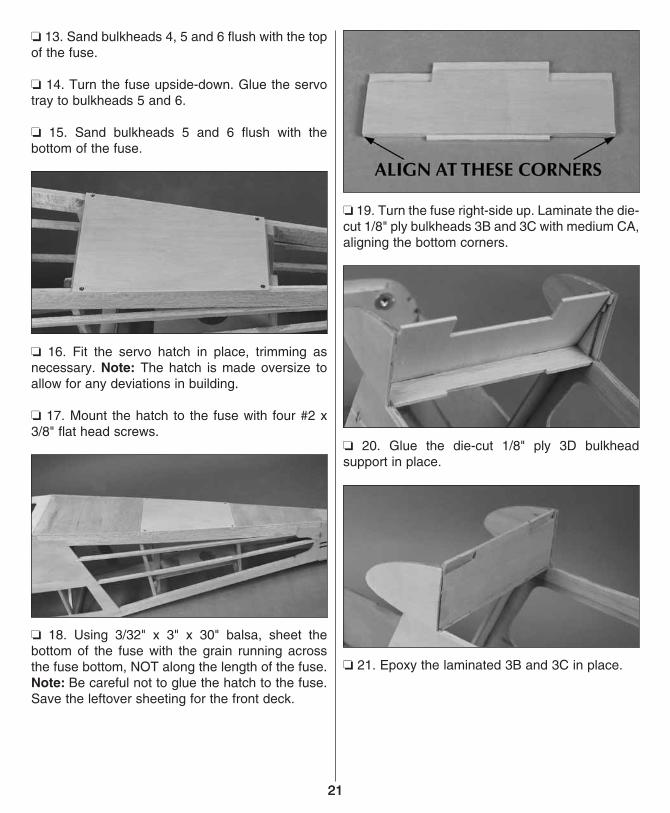
❏ 19. Turn the fuse right-side up. Laminate the die-cut 1/8" ply bulkheads 3B and 3C with medium CA, aligning the bottom corners.
❏ 20. Glue the die-cut 1/8" ply 3D bulkhead support in place.
❏ 21. Epoxy the laminated 3B and 3C in place.
21
❏ 22. Fit and epoxy the 1/4" x 1-3/4" x 5-3/4" ply wing bolt plate.
❏ 23. From a 1" x 1-3/4" x 6" balsa block, shape and glue the filler block to the top of the wing bolt plate.
MOUNT THE WING
❏ 1. Slide the wing halves together on the aluminum tube and center the wing on the fuse. Note: Be sure the wing halves are slid all the way onto the tube.
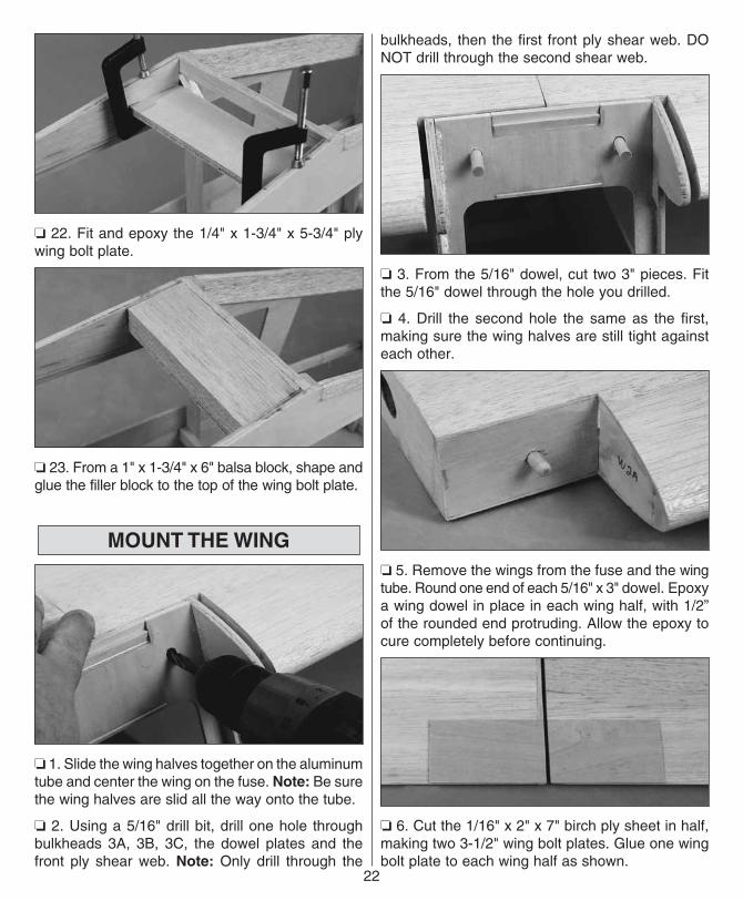
❏ 2. Using a 5/16" drill bit, drill one hole through bulkheads 3A, 3B, 3C, the dowel plates and the front ply shear web. Note: Only drill through the
bulkheads, then the first front ply shear web. DO NOT drill through the second shear web.
❏ 3. From the 5/16" dowel, cut two 3" pieces. Fit the 5/16" dowel through the hole you drilled.
❏ 4. Drill the second hole the same as the first, making sure the wing halves are still tight against each other.
❏ 5. Remove the wings from the fuse and the wing tube. Round one end of each 5/16" x 3" dowel. Epoxy a wing dowel in place in each wing half, with 1/2” of the rounded end protruding. Allow the epoxy to cure completely before continuing.
❏ 6. Cut the 1/16" x 2" x 7" birch ply sheet in half, making two 3-1/2" wing bolt plates. Glue one wing bolt plate to each wing half as shown.
22
23
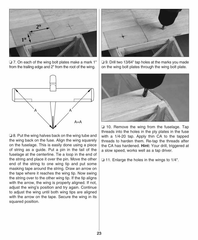
❏ 7. On each of the wing bolt plates make a mark 1" from the trailing edge and 2" from the root of the wing.
❏ 8. Put the wing halves back on the wing tube and the wing back on the fuse. Align the wing squarely on the fuselage. This is easily done using a piece of string as a guide. Put a pin in the tail of the fuselage at the centerline. Tie a loop in the end of the string and place it over the pin. Move the other end of the string to one wing tip and put some masking tape around the string. Draw an arrow on the tape where it reaches the wing tip. Now swing the string over to the other wing tip. If the tip aligns with the arrow, the wing is properly aligned. If not, adjust the wing’s position and try again. Continue to adjust the wing until both wing tips are aligned with the arrow on the tape. Secure the wing in its squared position.
❏ 9. Drill two 13/64" tap holes at the marks you made on the wing bolt plates through the wing bolt plate.
❏ 10. Remove the wing from the fuselage. Tap threads into the holes in the ply plates in the fuse with a 1/4-20 tap. Apply thin CA to the tapped threads to harden them. Re-tap the threads after the CA has hardened. Hint: Your drill, triggered at a slow speed, works well as a tap driver.
❏ 11. Enlarge the holes in the wings to 1/4".
23
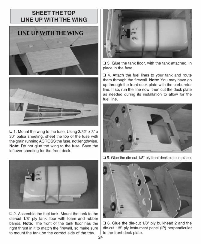
SHEET THE TOPLINE UP WITH THE WING
❏ 1. Mount the wing to the fuse. Using 3/32" x 3" x 30" balsa sheeting, sheet the top of the fuse with the grain running ACROSS the fuse, not lengthwise. Note: Do not glue the wing to the fuse. Save the leftover sheeting for the front deck.
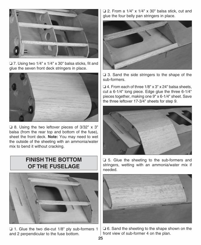
❏ 2. Assemble the fuel tank. Mount the tank to the die-cut 1/8" ply tank floor with foam and rubber bands. Note: The front of the tank floor has the right thrust in it to match the firewall, so make sure to mount the tank on the correct side of the tray.
❏ 3. Glue the tank floor, with the tank attached, in place in the fuse.
❏ 4. Attach the fuel lines to your tank and route them through the firewall. Note: You may have go up through the front deck plate with the carburetor line. If so, run the line now, then cut the deck plate as needed during its installation to allow for the fuel line.
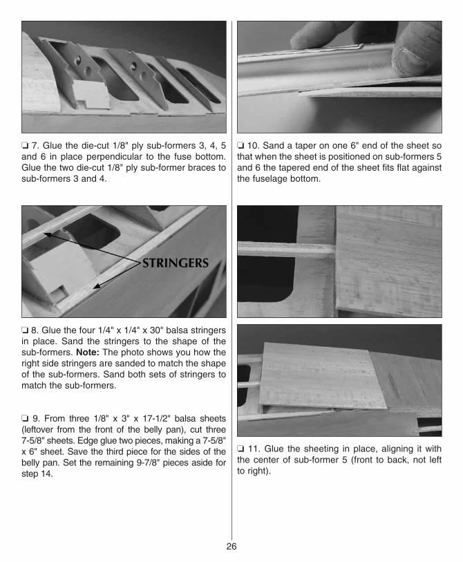
❏ 5. Glue the die-cut 1/8" ply front deck plate in place.
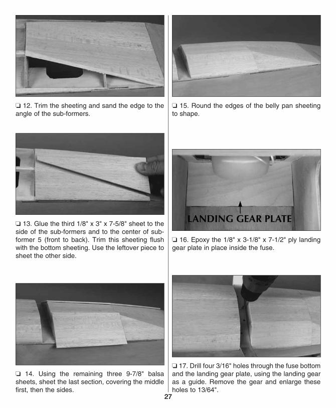
❏ 6. Glue the die-cut 1/8" ply bulkhead 2 and the die-cut 1/8" ply instrument panel (IP) perpendicular to the front deck plate.
24
2525
❏ 7. Using two 1/4" x 1/4" x 30" balsa sticks, fit and glue the seven front deck stringers in place.
❏ 8. Using the two leftover pieces of 3/32" x 3" balsa (from the rear top and bottom of the fuse), sheet the front deck. Note: You may need to wet the outside of the sheeting with an ammonia/water mix to bend it without cracking.
FINISH THE BOTTOMOF THE FUSELAGE
❏ 1. Glue the two die-cut 1/8" ply sub-formers 1 and 2 perpendicular to the fuse bottom.
❏ 2. From a 1/4" x 1/4" x 30" balsa stick, cut and glue the four belly pan stringers in place.
❏ 3. Sand the side stringers to the shape of the sub-formers.
❏ 4. From each of three 1/8" x 3" x 24" balsa sheets, cut a 6-1/4" long piece. Edge glue the three 6-1/4" pieces together, making one 9" x 6-1/4" sheet. Save the three leftover 17-3/4" sheets for step 9.
❏ 5. Glue the sheeting to the sub-formers and stringers, wetting with an ammonia/water mix if needed.
❏ 6. Sand the sheeting to the shape shown on the front view of sub-former 4 on the plan.
❏ 7. Glue the die-cut 1/8" ply sub-formers 3, 4, 5 and 6 in place perpendicular to the fuse bottom. Glue the two die-cut 1/8" ply sub-former braces to sub-formers 3 and 4.
❏ 8. Glue the four 1/4" x 1/4" x 30" balsa stringers in place. Sand the stringers to the shape of the sub-formers. Note: The photo shows you how the right side stringers are sanded to match the shape of the sub-formers. Sand both sets of stringers to match the sub-formers.
❏ 9. From three 1/8" x 3" x 17-1/2" balsa sheets (leftover from the front of the belly pan), cut three 7-5/8" sheets. Edge glue two pieces, making a 7-5/8" x 6" sheet. Save the third piece for the sides of the belly pan. Set the remaining 9-7/8" pieces aside for step 14.
❏ 10. Sand a taper on one 6" end of the sheet so that when the sheet is positioned on sub-formers 5 and 6 the tapered end of the sheet fits flat against the fuselage bottom.
❏ 11. Glue the sheeting in place, aligning it with the center of sub-former 5 (front to back, not left to right).
26
27
❏ 12. Trim the sheeting and sand the edge to the angle of the sub-formers.
❏ 13. Glue the third 1/8" x 3" x 7-5/8" sheet to the side of the sub-formers and to the center of sub-former 5 (front to back). Trim this sheeting flush with the bottom sheeting. Use the leftover piece to sheet the other side.
❏ 14. Using the remaining three 9-7/8" balsa sheets, sheet the last section, covering the middle first, then the sides.
❏ 15. Round the edges of the belly pan sheeting to shape.
❏ 16. Epoxy the 1/8" x 3-1/8" x 7-1/2" ply landing gear plate in place inside the fuse.
❏ 17. Drill four 3/16" holes through the fuse bottom and the landing gear plate, using the landing gear as a guide. Remove the gear and enlarge these holes to 13/64".
27
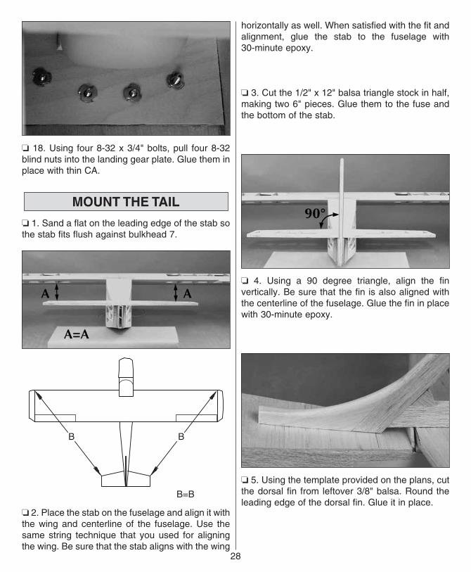
❏ 18. Using four 8-32 x 3/4" bolts, pull four 8-32 blind nuts into the landing gear plate. Glue them in place with thin CA.
MOUNT THE TAIL
❏ 1. Sand a flat on the leading edge of the stab so the stab fits flush against bulkhead 7.
❏ 2. Place the stab on the fuselage and align it with the wing and centerline of the fuselage. Use the same string technique that you used for aligning the wing. Be sure that the stab aligns with the wing
horizontally as well. When satisfied with the fit and alignment, glue the stab to the fuselage with 30-minute epoxy.
❏ 3. Cut the 1/2" x 12" balsa triangle stock in half, making two 6" pieces. Glue them to the fuse and the bottom of the stab.
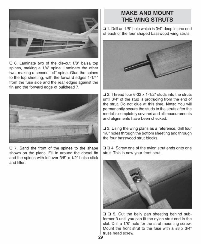
❏ 4. Using a 90 degree triangle, align the fin vertically. Be sure that the fin is also aligned with the centerline of the fuselage. Glue the fin in place with 30-minute epoxy.
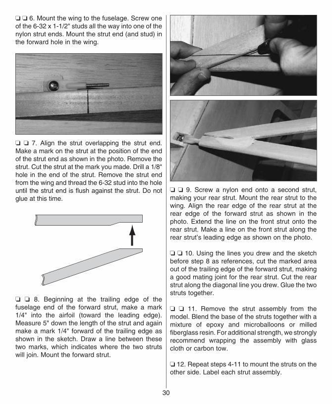
❏ 5. Using the template provided on the plans, cut the dorsal fin from leftover 3/8" balsa. Round the leading edge of the dorsal fin. Glue it in place.
28
29
❏ 6. Laminate two of the die-cut 1/8" balsa top spines, making a 1/4" spine. Laminate the other two, making a second 1/4" spine. Glue the spines to the top sheeting, with the forward edges 1-1/4" from the fuse side and the rear edges against the fin and the forward edge of bulkhead 7.
❏ 7. Sand the front of the spines to the shape shown on the plans. Fill in around the dorsal fin and the spines with leftover 3/8" x 1/2" balsa stick and filler.
MAKE AND MOUNTTHE WING STRUTS
❏ 1. Drill an 1/8" hole which is 3/4" deep in one end of each of the four shaped basswood wing struts.
❏ 2. Thread four 6-32 x 1-1/2" studs into the struts until 3/4" of the stud is protruding from the end of the strut. Do not glue at this time. Note: You will permanently secure the studs to the struts after the model is completely covered and all measurements and alignments have been checked.
❏ 3. Using the wing plans as a reference, drill four 1/8" holes through the bottom sheeting and through the four basswood strut blocks.
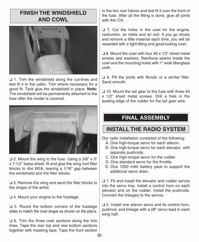
❏ ❏ 4. Screw one of the nylon strut ends onto one strut. This is now your front strut.
❏ ❏ 5. Cut the belly pan sheeting behind sub-former 3 until you can fit the nylon strut end in the slot. Drill a 1/8" hole for the strut mounting screw. Mount the front strut to the fuse with a #8 x 3/4" truss head screw.
29
❏ ❏ 6. Mount the wing to the fuselage. Screw one of the 6-32 x 1-1/2" studs all the way into one of the nylon strut ends. Mount the strut end (and stud) in the forward hole in the wing.
❏ ❏ 7. Align the strut overlapping the strut end. Make a mark on the strut at the position of the end of the strut end as shown in the photo. Remove the strut. Cut the strut at the mark you made. Drill a 1/8" hole in the end of the strut. Remove the strut end from the wing and thread the 6-32 stud into the hole until the strut end is flush against the strut. Do not glue at this time.
❏ ❏ 8. Beginning at the trailing edge of the fuselage end of the forward strut, make a mark 1/4" into the airfoil (toward the leading edge). Measure 5" down the length of the strut and again make a mark 1/4" forward of the trailing edge as shown in the sketch. Draw a line between these two marks, which indicates where the two struts will join. Mount the forward strut.
❏ ❏ 9. Screw a nylon end onto a second strut, making your rear strut. Mount the rear strut to the wing. Align the rear edge of the rear strut at the rear edge of the forward strut as shown in the photo. Extend the line on the front strut onto the rear strut. Make a line on the front strut along the rear strut’s leading edge as shown on the photo.
❏ ❏ 10. Using the lines you drew and the sketch before step 8 as references, cut the marked area out of the trailing edge of the forward strut, making a good mating joint for the rear strut. Cut the rear strut along the diagonal line you drew. Glue the two struts together.
❏ ❏ 11. Remove the strut assembly from the model. Blend the base of the struts together with a mixture of epoxy and microballoons or milled fiberglass resin. For additional strength, we strongly recommend wrapping the assembly with glass cloth or carbon tow.
❏ 12. Repeat steps 4-11 to mount the struts on the other side. Label each strut assembly.
30
31
FINISH THE WINDSHIELDAND COWL
❏ 1. Trim the windshield along the cut-lines and test fit it to the cabin. Trim where necessary for a good fit. Tack glue the windshield in place. Note: The windshield will be permanently attached to the fuse after the model is covered.
❏ 2. Mount the wing to the fuse. Using a 3/8" x 3" x 7-1/2" balsa sheet, fit and glue the wing root filler blocks to ribs W2A, leaving a 1/16" gap between the windshield and the filler blocks.
❏ 3. Remove the wing and sand the filler blocks to the shape of the airfoil.
❏ 4. Mount your engine to the fuselage.
❏ 5. Round the bottom corners of the fuselage sides to match the cowl shape as shown on the plans.
❏ 6. Trim the three cowl sections along the trim lines. Tape the rear top and rear bottom sections together with masking tape. Tape the front section
to the two rear halves and test fit it over the front of the fuse. After all the fitting is done, glue all joints with thin CA.
❏ 7. Cut the holes in the cowl for the engine, carburetor, air inlets and air exit. If you go slowly and remove a little material each time, you will be rewarded with a tight-fitting and good-looking cowl.
❏ 8. Mount the cowl with four #6 x 1/2" sheet metal screws and washers. Reinforce seams inside the cowl and the mounting holes with 1" wide fiberglass cloth.
❏ 9. Fill the joints with Bondo or a similar filler.Sand smooth.
❏ 10. Mount the tail gear to the fuse with three #4 x 1/2" sheet metal screws. Drill a hole in the leading edge of the rudder for the tail gear wire.
FINAL ASSEMBLY
INSTALL THE RADIO SYSTEM
Our radio installation consisted of the following: A. One high-torque servo for each aileron. B. One high-torque servo for each elevator, with
separate pushrods. C. One high-torque servo for the rudder. D. One standard servo for the throttle. E. One 1200 mAh battery pack to support the
additional servo drain.
❏ 1. Fit and install the elevator and rudder servos into the servo tray. Install a control horn on each elevator and on the rudder. Install the pushrods. Connect the linkages to the servos.
❏ 2. Install one aileron servo and its control horn, pushrod, and linkage with a 28" servo lead in each wing half.
31
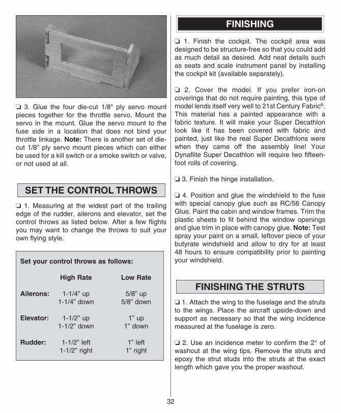
❏ 3. Glue the four die-cut 1/8" ply servo mount pieces together for the throttle servo. Mount the servo in the mount. Glue the servo mount to the fuse side in a location that does not bind your throttle linkage. Note: There is another set of die-cut 1/8" ply servo mount pieces which can either be used for a kill switch or a smoke switch or valve, or not used at all.
SET THE CONTROL THROWS
❏ 1. Measuring at the widest part of the trailing edge of the rudder, ailerons and elevator, set the control throws as listed below. After a few flights you may want to change the throws to suit your own flying style.
Set your control throws as follows:
High Rate Low Rate
Ailerons: 1-1/4” up 5/8” up 1-1/4” down 5/8” down
Elevator: 1-1/2” up 1” up 1-1/2” down 1” down
Rudder: 1-1/2” left 1” left 1-1/2” right 1” right
FINISHING
❏ 1. Finish the cockpit. The cockpit area was designed to be structure-free so that you could add as much detail as desired. Add neat details such as seats and scale instrument panel by installing the cockpit kit (available separately).
❏ 2. Cover the model. If you prefer iron-on coverings that do not require painting, this type of model lends itself very well to 21st Century Fabric®. This material has a painted appearance with a fabric texture. It will make your Super Decathlon look like it has been covered with fabric and painted, just like the real Super Decathlons were when they came off the assembly line! Your Dynaflite Super Decathlon will require two fifteen-foot rolls of covering.
❏ 3. Finish the hinge installation.
❏ 4. Position and glue the windshield to the fuse with special canopy glue such as RC/56 Canopy Glue. Paint the cabin and window frames. Trim the plastic sheets to fit behind the window openings and glue trim in place with canopy glue. Note: Test spray your paint on a small, leftover piece of your butyrate windshield and allow to dry for at least 48 hours to ensure compatibility prior to painting your windshield.
FINISHING THE STRUTS
❏ 1. Attach the wing to the fuselage and the struts to the wings. Place the aircraft upside-down and support as necessary so that the wing incidence measured at the fuselage is zero.
❏ 2. Use an incidence meter to confirm the 2° of washout at the wing tips. Remove the struts and epoxy the strut studs into the struts at the exact length which gave you the proper washout.
32
33
BALANCE THE MODEL LATERALLY
Do not confuse this procedure with “checking the C.G.” which will be discussed later in the manual.
Now that the model is covered and nearly completed, this is the time to balance it laterally (side-to-side). Here’s how:
❏ 1. With the wing level and attached to the model (and the engine and muffler installed), lift the model by the propeller shaft and the fin. This may require an assistant. Do this several times.
❏ 2. The wing that consistently drops indicates the heavy side. Balance the model by adding weight to the other wing tip.
An airplane that is laterally balanced will track better during aerobatic maneuvers.
BALANCE YOUR MODEL
This section is important and must not be omitted. A model that is not properly balanced will be unstable and possibly unflyable. Note: You must check the balance point with all components installed in the model and the fuel tank empty.
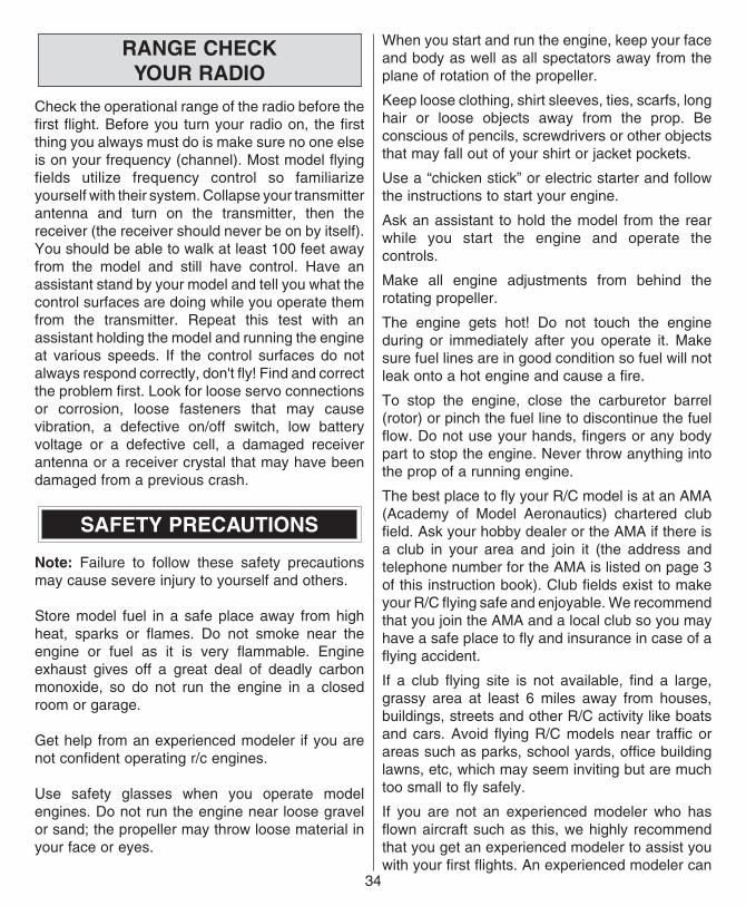
❏ 1. Attach the wing and struts to the fuselage. Then, accurately mark the balance point on the bottom of both wing halves next to the fuselage. Check and set the CG as shown on the plan at 3-3/8" aft of the leading edge. After your first flights, the CG can be adjusted fore or aft up to 1/2" from the optimum CG to fit your flying style.
PREFLIGHT
BALANCE YOUR PROPELLERS
Many problems are the result of vibration caused by an unbalanced propeller. Nuts and bolts can vibrate loose. Vibration can damage delicate radio components and even damage the delicate glow plug element, resulting in an engine that is difficult or impossible to start. Purchase a Top Flite Precision Magnetic Balancer™ or a Great Planes Fingertip Prop Balancer to accurately balance your propellers.
CHARGE YOUR BATTERIES
Follow the battery charging instructions in the instruction manual that came with your radio control system. You should always charge your batteries the night before you fly.
AT THE FLYING SITE
GROUND CHECKYOUR MODEL
Inspect all nuts, screws and wheel collars. Make sure that you installed the screws that hold the servo arms onto the servos and that the servo wires are securely connected to the receiver. If you are not thoroughly familiar with R/C models, ask an experienced modeler to inspect your radio installation and make sure the control surfaces respond correctly. The engine must be “broken-in” according to the engine manufacturer's recommendations for break-in. Refer to the Safety Precautions on this page before you start your engine. After you run the engine on the model, make sure all screws remain tight, the hinges are secure and the prop is on tight.
33
RANGE CHECKYOUR RADIO
Check the operational range of the radio before the first flight. Before you turn your radio on, the first thing you always must do is make sure no one else is on your frequency (channel). Most model flying fields utilize frequency control so familiarize yourself with their system. Collapse your transmitter antenna and turn on the transmitter, then the receiver (the receiver should never be on by itself). You should be able to walk at least 100 feet away from the model and still have control. Have an assistant stand by your model and tell you what the control surfaces are doing while you operate them from the transmitter. Repeat this test with an assistant holding the model and running the engine at various speeds. If the control surfaces do not always respond correctly, don't fly! Find and correct the problem first. Look for loose servo connections or corrosion, loose fasteners that may cause vibration, a defective on/off switch, low battery voltage or a defective cell, a damaged receiver antenna or a receiver crystal that may have been damaged from a previous crash.
SAFETY PRECAUTIONS
Note: Failure to follow these safety precautions may cause severe injury to yourself and others.
Store model fuel in a safe place away from high heat, sparks or flames. Do not smoke near the engine or fuel as it is very flammable. Engine exhaust gives off a great deal of deadly carbon monoxide, so do not run the engine in a closed room or garage.
Get help from an experienced modeler if you are not confident operating r/c engines.
Use safety glasses when you operate model engines. Do not run the engine near loose gravel or sand; the propeller may throw loose material in your face or eyes.
When you start and run the engine, keep your face and body as well as all spectators away from the plane of rotation of the propeller.
Keep loose clothing, shirt sleeves, ties, scarfs, long hair or loose objects away from the prop. Be conscious of pencils, screwdrivers or other objects that may fall out of your shirt or jacket pockets.
Use a “chicken stick” or electric starter and follow the instructions to start your engine.
Ask an assistant to hold the model from the rear while you start the engine and operate the controls.
Make all engine adjustments from behind the rotating propeller.
The engine gets hot! Do not touch the engine during or immediately after you operate it. Make sure fuel lines are in good condition so fuel will not leak onto a hot engine and cause a fire.
To stop the engine, close the carburetor barrel (rotor) or pinch the fuel line to discontinue the fuel flow. Do not use your hands, fingers or any body part to stop the engine. Never throw anything into the prop of a running engine.
The best place to fly your R/C model is at an AMA (Academy of Model Aeronautics) chartered club field. Ask your hobby dealer or the AMA if there is a club in your area and join it (the address and telephone number for the AMA is listed on page 3 of this instruction book). Club fields exist to make your R/C flying safe and enjoyable. We recommend that you join the AMA and a local club so you may have a safe place to fly and insurance in case of a flying accident.
If a club flying site is not available, find a large, grassy area at least 6 miles away from houses, buildings, streets and other R/C activity like boats and cars. Avoid flying R/C models near traffic or areas such as parks, school yards, office building lawns, etc, which may seem inviting but are much too small to fly safely.
If you are not an experienced modeler who has flown aircraft such as this, we highly recommend that you get an experienced modeler to assist you with your first flights. An experienced modeler can
34
35
take your Super Decathlon up for the first time and make sure it performs correctly, then give you valuable flight instruction. He can hand you the transmitter when the Super Decathlon has climbed to a safe altitude or connect your transmitter to his if both of your systems have a trainer cord or “buddy box” capability. Assistance from an experienced modeler will make your modeling “career” progress faster (and cheaper).
FLIGHT
TAKEOFF
First flight attempts should be reserved for calm days when the wind speed is less than five mph. Always takeoff (and land) into the wind. Check the operation of all controls just before takeoff. This will eliminate the possibility of overlooking reversed or disconnected controls (it happens).
As you apply power on takeoff, you will need to apply a slight amount of right rudder to compensate for engine torque and propeller “P” effect. The tail will rise almost immediately, indicating that the tail surfaces have gained effectiveness. Allow the model to continue to accelerate until it has reached flying speed. Use as much of the available runway as you can. Then, gently apply some up elevator. Your Super Decathlon should slowly lift from the runway. Continue straight ahead until you have accelerated to a safe flying speed.
FLYING
As an aerobatic trainer, the full-scale Decathlon is used to teach takeoffs, landings, turns, stalls, spins and gentle aerobatics. Being relatively low-powered, it does not have a high rate of climb and has poor vertical performance. To gain speed for a loop, it is necessary to dive for a brief period. Barrel rolls are slow, teaching rudder/elevator coordination. While the Super Decathlon is a more powerful and advanced model, it still has most of
the same basic flying characteristics. Your Dynaflite Super Decathlon faithfully duplicates these same characteristics.
To fly your Super Decathlon in a scale-like manner, you should work on coordinating your turns by using a little rudder in addition to the ailerons. You can do this manually or use a computer radio to mix-in some rudder with ailerons.
LANDING
Before attempting your first landing you should first try some slow flight and stalls at higher altitudes to become familiar with the Super Decathlon's slow speed characteristics. You will probably find the model slows down quicker and requires more power than you are used to. Remember that aircraft of the Super Decathlon's era had high drag and limited low speed control effectiveness, especially for the ailerons. The rudder is very effective, however. Continue to carry approximately 1/4 power and speed until you initiate the flare, then reduce power and allow the model to gently settle to the ground. If you must go around, add power and accelerate straight ahead. Do not attempt to climb or turn until you have accelerated to a safe flying speed.
We hope you enjoy the realistic looks and performance of your Super Decathlon.
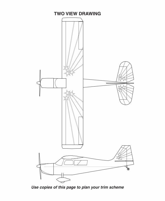
TWO VIEW DRAWING
Use copies of this page to plan your trim scheme


![INSTRUCTION MANUAL - Hobbico, Inc. - largest U.S ...manuals.hobbico.com/flz/flza2102-manual.pdfFLZA2102 SPECIFICATIONS Wingspan: 15.9 in [404mm] Total Length: 15.7 in [399mm] Weight:](https://img.pdfslide.us/doc/110x75/5aa505477f8b9ae7438cd38c/instruction-manual-hobbico-inc-largest-us-specifications-wingspan-159.jpg)