Embed Size (px)
Citation preview
July 1, 2005Lit. No. 28270, Rev. 00
MECHANIC'S GUIDEMECHANIC'S GUIDEMECHANIC'S GUIDEMECHANIC'S GUIDEMECHANIC'S GUIDE
SNOSNOSNOSNOSNOWPLWPLWPLWPLWPLOOOOOWSWSWSWSWSFeaturing the
FFFFFloStaloStaloStaloStaloStattttt®®®®® Hy Hy Hy Hy Hydrdrdrdrdraulic System &aulic System &aulic System &aulic System &aulic System &IsolaIsolaIsolaIsolaIsolation Module Light Systemtion Module Light Systemtion Module Light Systemtion Module Light Systemtion Module Light System
SNOSNOSNOSNOSNOWPLWPLWPLWPLWPLOOOOOWSWSWSWSWS
CAUTIONRead this manual before servicing the snowplow.

Lit. No. 28270, Rev. 00 July 1, 2005
3
TABLE OF CONTENTS
Introduction .................................................................................................... 4Preface ...................................................................................................... 4Required Tools ......................................................................................... 4Available Service Items ........................................................................... 4
Safety Information .......................................................................................... 5System Overview............................................................................................ 8
Blade, T-Frame & Lift Assemblies .......................................................... 8Snowplow Components .................................................................... 8Securing Pivot Bar to T-Frame ......................................................... 8Pivot Plates ........................................................................................ 9Initial Stand Shoe Setup .................................................................. 10Stand Shoe Adjustment .................................................................. 10Stacking Stop Configuration .......................................................... 11T-Frame Leveling Adjustment ........................................................ 12Blade Spring Replacement Tool (PN 20043) ................................. 13Lift Arm & Lift Ram Installation ...................................................... 14Headlamp Beam Aiming ................................................................. 15Vehicle Lighting Check ................................................................... 15
Hydraulic ................................................................................................ 16FloStat® Hydraulic System .............................................................. 16Specifications .................................................................................. 16Hydraulic Fitting and Hose Installation ......................................... 17Hose Routing and Fitting Orientation ............................................ 18Assembly ......................................................................................... 19Cartridge Valves .............................................................................. 20Relief Valves .................................................................................... 21Pilot-Operated Check Valves .......................................................... 22Ram Seal Installation ...................................................................... 23
Electrical ................................................................................................. 24Wiring ............................................................................................... 24
Controls .................................................................................................. 25General Information ........................................................................ 25Adapter Cable (PN 66760K) ............................................................ 25CabCommand Hand-Held Control (9 Button) ................................ 26Joystick Control .............................................................................. 28CabCommand Hand-Held Control (6 Button) ................................ 30Fuse Replacement ........................................................................... 32Terminal Removal Tool .................................................................... 33Replacing Terminals ........................................................................ 3314-Pin Connector Pin Assignments ............................................... 33
Theory of Operation ..................................................................................... 34Snowplow Headlamps ........................................................................... 34Snowplow Daytime Running Lights ..................................................... 34Snowplow Hydraulics ............................................................................ 34
Electrical & Hydraulic Schematics.............................................................. 35Electrical Schematic .............................................................................. 36Hydraulic Schematic .............................................................................. 37Raise ....................................................................................................... 38Lower ...................................................................................................... 40Angle Right ............................................................................................. 42Angle Left ............................................................................................... 44Vee .......................................................................................................... 46Scoop ...................................................................................................... 48Right Retract .......................................................................................... 50Right Extend ........................................................................................... 52Left Retract ............................................................................................. 54Left Extend ............................................................................................. 56Hold in Raised Position ......................................................................... 58Striking An Object While Plowing ........................................................ 59High Beam Headlamps with Snowplow Connected to Vehicle .......... 61Low Beam Headlamps with Snowplow Connected to Vehicle........... 62
Troubleshooting Guide ................................................................................ 63
Lit. No. 28270, Rev. 00 July 1, 2005
4
PREFACE
This guide has been prepared toassist the trained mechanic in theservice of WESTERN® snowplows. Italso provides safety information andrecommendations. We urge allmechanics to read this manualcarefully before attempting to servicethe WESTERN snowplow equipmentcovered by this guide.
INTRODUCTION
Service of your WESTERNsnowplow equipment is bestperformed by your local WesternProducts outlet. They know yoursnowplow best and are interested inyour complete satisfaction.
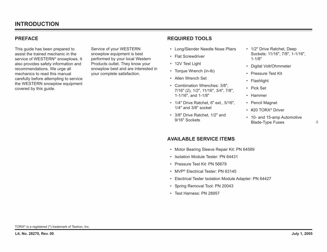
REQUIRED TOOLS
• Long/Slender Needle Nose Pliers
• Flat Screwdriver
• 12V Test Light
• Torque Wrench (in-lb)
• Allen Wrench Set
• Combination Wrenches: 3/8",7/16" (2), 1/2", 11/16", 3/4", 7/8",1-1/16", and 1-1/8"
• 1/4" Drive Ratchet, 6" ext., 5/16",1/4" and 3/8" socket
• 3/8" Drive Ratchet, 1/2" and9/16" Sockets
• 1/2" Drive Ratchet, DeepSockets: 11/16", 7/8", 1-1/16",1-1/8"
• Digital Volt/Ohmmeter
• Pressure Test Kit
• Flashlight
• Pick Set
• Hammer
• Pencil Magnet
• #20 TORX® Driver
• 10- and 15-amp AutomotiveBlade-Type Fuses
TORX® is a registered (®) trademark of Textron, Inc.
AVAILABLE SERVICE ITEMS
• Motor Bearing Sleeve Repair Kit: PN 64589
• Isolation Module Tester: PN 64431
• Pressure Test Kit: PN 56679
• MVP® Electrical Tester: PN 63145
• Electrical Tester Isolation Module Adapter: PN 64427
• Spring Removal Tool: PN 20043
• Test Harness: PN 28957
Lit. No. 28270, Rev. 00 July 1, 2005
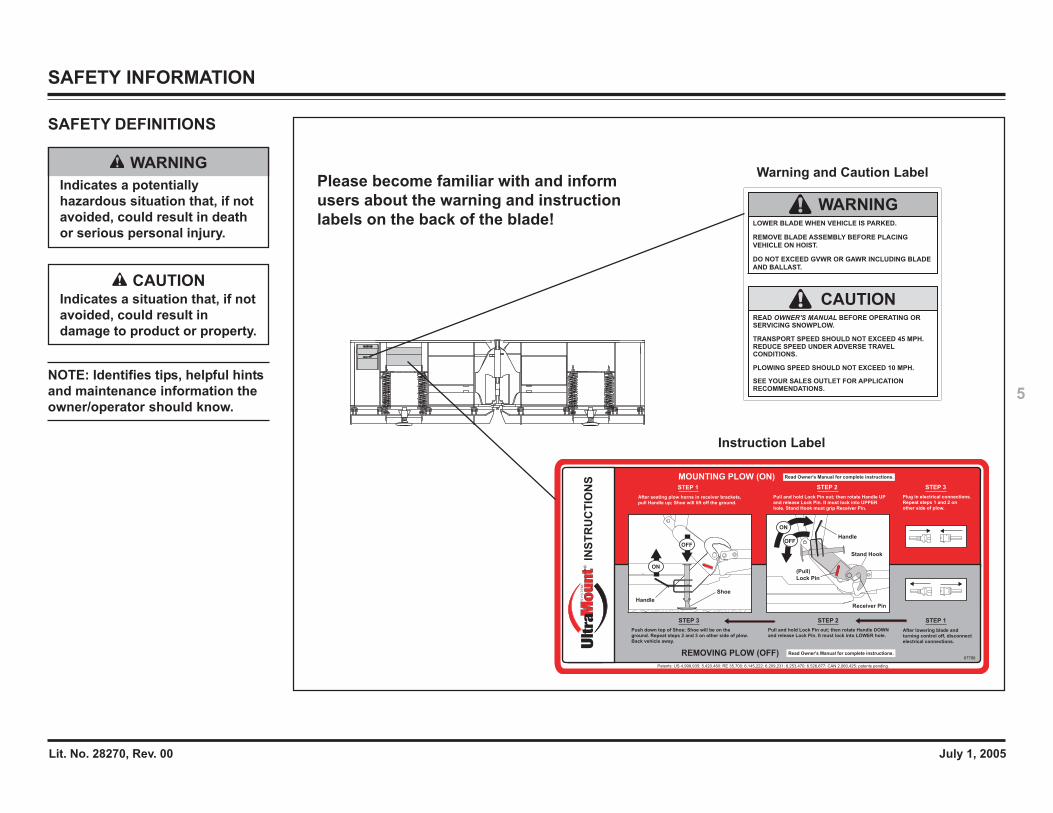
5NOTE: Identifies tips, helpful hintsand maintenance information theowner/operator should know.
SAFETY INFORMATION
INS
TR
UC
TIO
NS
Pull and hold Lock Pin out; then rotate Handle DOWN
and release Lock Pin. It must lock into LOWER hole. Push down top of Shoe; Shoe will be on the
ground. Repeat steps 2 and 3 on other side of plow.
Back vehicle away.
After lowering blade and
turning control off, disconnect
electrical connections.
STEP 3 STEP 2 STEP 1
After seating plow horns in receiver brackets,
pull Handle up; Shoe will lift off the ground.
Pull and hold Lock Pin out; then rotate Handle UP
and release Lock Pin. It must lock into UPPER
hole. Stand Hook must grip Receiver Pin.
Plug in electrical connections.
Repeat steps 1 and 2 on
other side of plow.
STEP 1 STEP 2 STEP 3
ON
OFFOFF
ON
Receiver Pin
Stand Hook
Handle
(Pull)
Lock Pin
Shoe
Handle
MOUNTING PLOW (ON) Read Owner's Manual for complete instructions.
REMOVING PLOW (OFF) Read Owner's Manual for complete instructions.
Patents: US 4,999,935; 5,420,480; RE 35,700; 6,145,222; 6,209,231; 6,253,470; 6,526,677; CAN 2,060,425; patents pending.
67796
®
Please become familiar with and informusers about the warning and instructionlabels on the back of the blade!
Warning and Caution Label
Instruction Label
CAUTIONIndicates a situation that, if notavoided, could result indamage to product or property.
WARNINGIndicates a potentiallyhazardous situation that, if notavoided, could result in deathor serious personal injury.
SAFETY DEFINITIONS
Lit. No. 28270, Rev. 00 July 1, 2005
6
SAFETY INFORMATION
SAFETY PRECAUTIONS
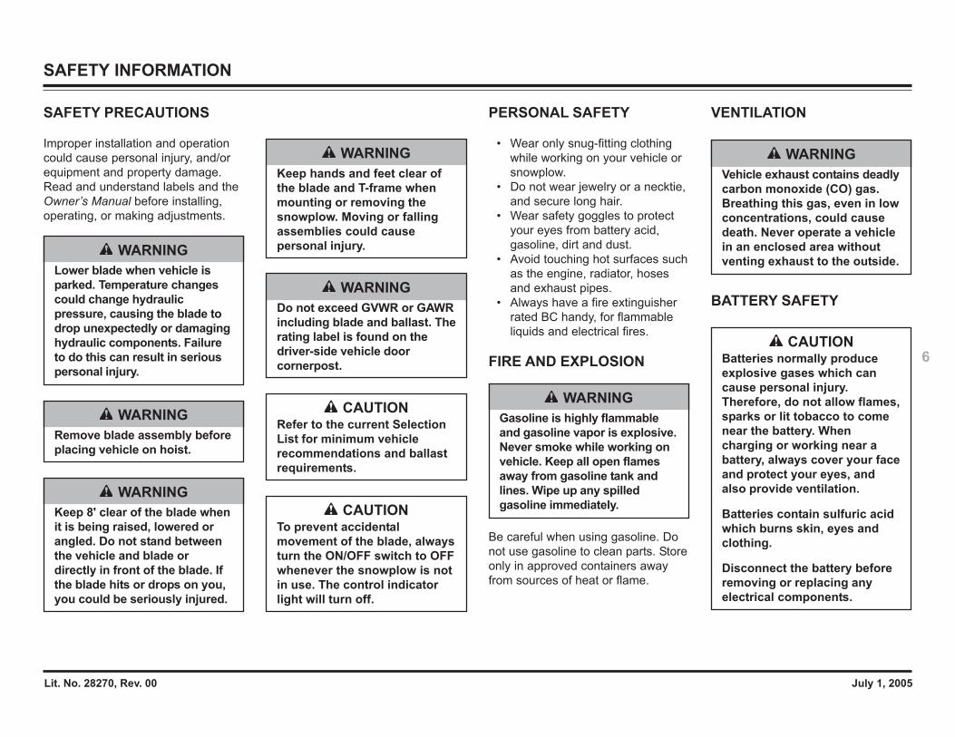
Improper installation and operationcould cause personal injury, and/orequipment and property damage.Read and understand labels and theOwner’s Manual before installing,operating, or making adjustments.
WARNINGLower blade when vehicle isparked. Temperature changescould change hydraulicpressure, causing the blade todrop unexpectedly or damaginghydraulic components. Failureto do this can result in seriouspersonal injury.
WARNINGRemove blade assembly beforeplacing vehicle on hoist.
WARNINGKeep 8' clear of the blade whenit is being raised, lowered orangled. Do not stand betweenthe vehicle and blade ordirectly in front of the blade. Ifthe blade hits or drops on you,you could be seriously injured.
WARNINGKeep hands and feet clear ofthe blade and T-frame whenmounting or removing thesnowplow. Moving or fallingassemblies could causepersonal injury.
WARNINGDo not exceed GVWR or GAWRincluding blade and ballast. Therating label is found on thedriver-side vehicle doorcornerpost.
CAUTIONRefer to the current SelectionList for minimum vehiclerecommendations and ballastrequirements.
CAUTIONTo prevent accidentalmovement of the blade, alwaysturn the ON/OFF switch to OFFwhenever the snowplow is notin use. The control indicatorlight will turn off.
PERSONAL SAFETY
• Wear only snug-fitting clothingwhile working on your vehicle orsnowplow.
• Do not wear jewelry or a necktie,and secure long hair.
• Wear safety goggles to protectyour eyes from battery acid,gasoline, dirt and dust.
• Avoid touching hot surfaces suchas the engine, radiator, hosesand exhaust pipes.
• Always have a fire extinguisherrated BC handy, for flammableliquids and electrical fires.
FIRE AND EXPLOSION
Be careful when using gasoline. Donot use gasoline to clean parts. Storeonly in approved containers awayfrom sources of heat or flame.
WARNINGGasoline is highly flammableand gasoline vapor is explosive.Never smoke while working onvehicle. Keep all open flamesaway from gasoline tank andlines. Wipe up any spilledgasoline immediately.
VENTILATION
BATTERY SAFETY
WARNINGVehicle exhaust contains deadlycarbon monoxide (CO) gas.Breathing this gas, even in lowconcentrations, could causedeath. Never operate a vehiclein an enclosed area withoutventing exhaust to the outside.
CAUTIONBatteries normally produceexplosive gases which cancause personal injury.Therefore, do not allow flames,sparks or lit tobacco to comenear the battery. Whencharging or working near abattery, always cover your faceand protect your eyes, andalso provide ventilation.
Batteries contain sulfuric acidwhich burns skin, eyes andclothing.
Disconnect the battery beforeremoving or replacing anyelectrical components.
Lit. No. 28270, Rev. 00 July 1, 2005
7
SAFETY INFORMATION
HYDRAULIC SAFETY
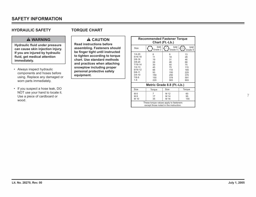
• Always inspect hydrauliccomponents and hoses beforeusing. Replace any damaged orworn parts immediately.
• If you suspect a hose leak, DONOT use your hand to locate it.Use a piece of cardboard orwood.
WARNINGHydraulic fluid under pressurecan cause skin injection injury.If you are injured by hydraulicfluid, get medical attentionimmediately.
TORQUE CHART
CAUTIONRead instructions beforeassembling. Fasteners shouldbe finger tight until instructedto tighten according to torquechart. Use standard methodsand practices when attachingsnowplow including properpersonal protective safetyequipment.
Recommended Fastener Torque Chart (Ft.-Lb.)
SizeSAE
Grade 2SAE
Grade 5SAE
Grade 8
1/4-205/16-183/8-163/8-247/16-141/2-139/16-125/8-11 3/4-10 7/8-9 1-8
611192430456693150150220
91831465075110150250378583
1328 46 68 75 115 165 225 370 591 893
Metric Grade 8.8 (Ft.-Lb.)
Size TorqueSizeTorque
M 6M 8M 10
M 12M 14M 16
717 35
60 95 155
These torque values apply to fastenersexcept those noted in the instruction.
Lit. No. 28270, Rev. 00 July 1, 2005
8
SYSTEM OVERVIEW – BLADE, T-FRAME & LIFT ASSEMBLIES
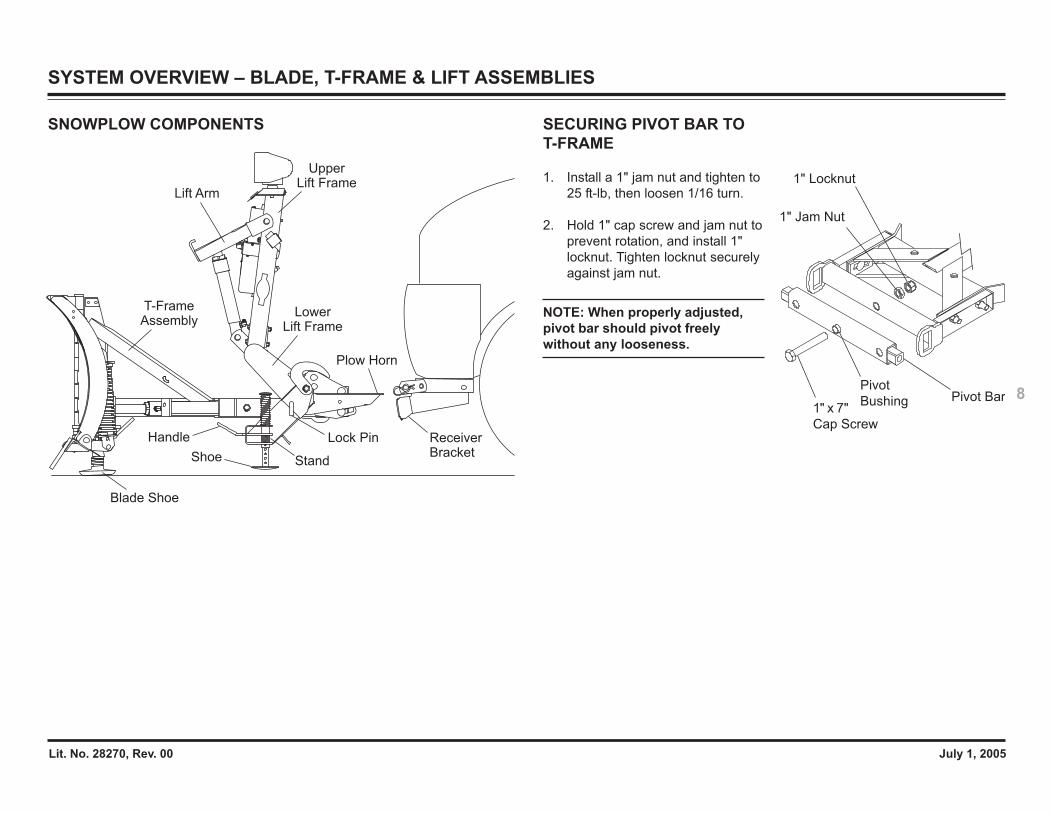
SNOWPLOW COMPONENTS
Plow Horn
Lift Arm
UpperLift Frame
T-FrameAssembly
LowerLift Frame
Receiver Bracket
Lock Pin
Shoe
Handle
Blade Shoe
Stand
SECURING PIVOT BAR TOT-FRAME
1. Install a 1" jam nut and tighten to25 ft-lb, then loosen 1/16 turn.
2. Hold 1" cap screw and jam nut toprevent rotation, and install 1"locknut. Tighten locknut securelyagainst jam nut.
NOTE: When properly adjusted,pivot bar should pivot freelywithout any looseness.
1" Locknut
1" Jam Nut
Pivot BarPivot
Bushing1" x 7"
Cap Screw
Lit. No. 28270, Rev. 00 July 1, 2005
9
Configuration 3
Configuration 4
Pivot Plate B (Flat Side Up)
Pivot
Pin
Pivot
PinPivot Plate A(Flat Side Up)
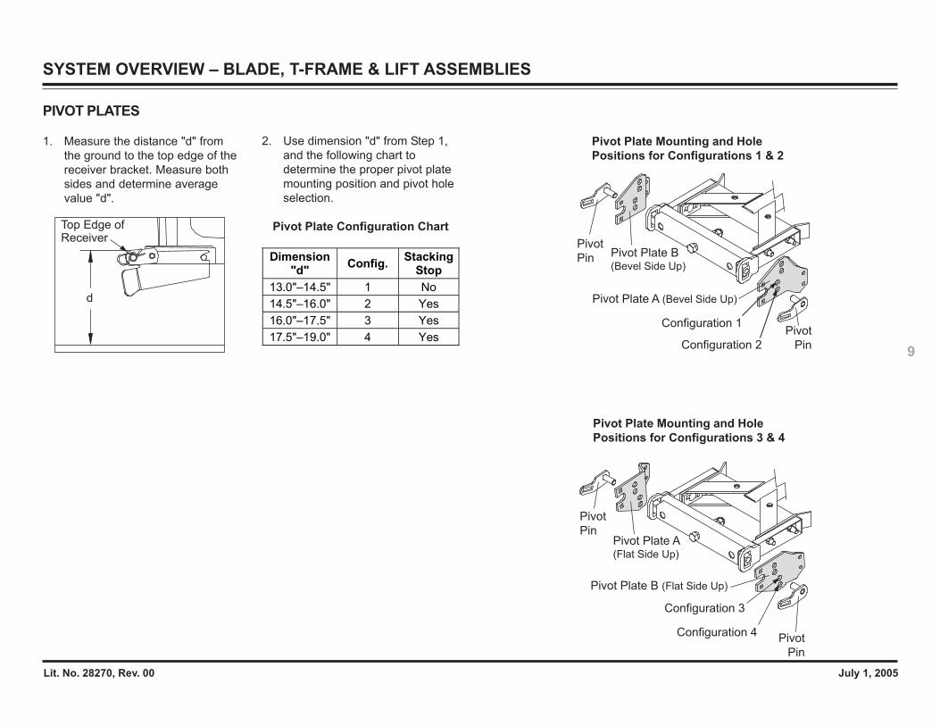
PIVOT PLATES
1. Measure the distance "d" fromthe ground to the top edge of thereceiver bracket. Measure bothsides and determine averagevalue "d".
d
Top Edge ofReceiver
Pivot Plate A (Bevel Side Up)
Configuration 1
Configuration 2
Pivot
Pin
Pivot
Pin Pivot Plate B(Bevel Side Up)
Dimension "d" Config. Stacking
Stop 13.0"–14.5" 1 No 14.5"–16.0" 2 Yes 16.0"–17.5" 3 Yes 17.5"–19.0" 4 Yes
Pivot Plate Mounting and HolePositions for Configurations 1 & 2
Pivot Plate Mounting and HolePositions for Configurations 3 & 4
2. Use dimension "d" from Step 1,and the following chart todetermine the proper pivot platemounting position and pivot holeselection.
Pivot Plate Configuration Chart
SYSTEM OVERVIEW – BLADE, T-FRAME & LIFT ASSEMBLIES
Lit. No. 28270, Rev. 00 July 1, 2005
10
SYSTEM OVERVIEW – BLADE, T-FRAME & LIFT ASSEMBLIES
Config. 1
Config. 2
Config. 3
Config. 4
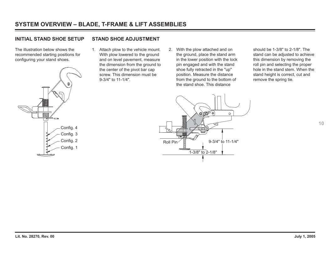
INITIAL STAND SHOE SETUP
The illustration below shows therecommended starting positions forconfiguring your stand shoes.
9-3/4" to 11-1/4"
1-3/8" to 2-1/8"
Roll Pin
STAND SHOE ADJUSTMENT
1. Attach plow to the vehicle mount.With plow lowered to the groundand on level pavement, measurethe dimension from the ground tothe center of the pivot bar capscrew. This dimension must be9-3/4" to 11-1/4".
2. With the plow attached and onthe ground, place the stand armin the lower position with the lockpin engaged and with the standshoe fully retracted in the "up"position. Measure the distancefrom the ground to the bottom ofthe stand shoe. This distance
should be 1-3/8" to 2-1/8". Thestand can be adjusted to achievethis dimension by removing theroll pin and selecting the properhole in the stand stem. When thestand height is correct, cut andremove the spring tie.
Lit. No. 28270, Rev. 00 July 1, 2005
11Stacking Stops
CapScrews
Locknuts
Cross Tube
MountingBracket
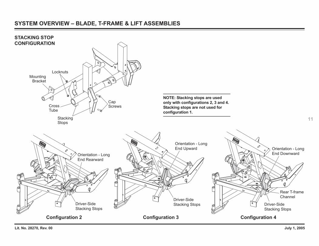
NOTE: Stacking stops are usedonly with configurations 2, 3 and 4.Stacking stops are not used forconfiguration 1.
STACKING STOPCONFIGURATION
SYSTEM OVERVIEW – BLADE, T-FRAME & LIFT ASSEMBLIES
Configuration 2
Driver-Side
Stacking Stops
Orientation - Long
End Rearward
Configuration 3
Driver-Side
Stacking Stops
Orientation - Long
End Upward
Configuration 4
Driver-Side
Stacking Stops
Rear T-frame
Channel
Orientation - Long
End Downward
Lit. No. 28270, Rev. 00 July 1, 2005
12
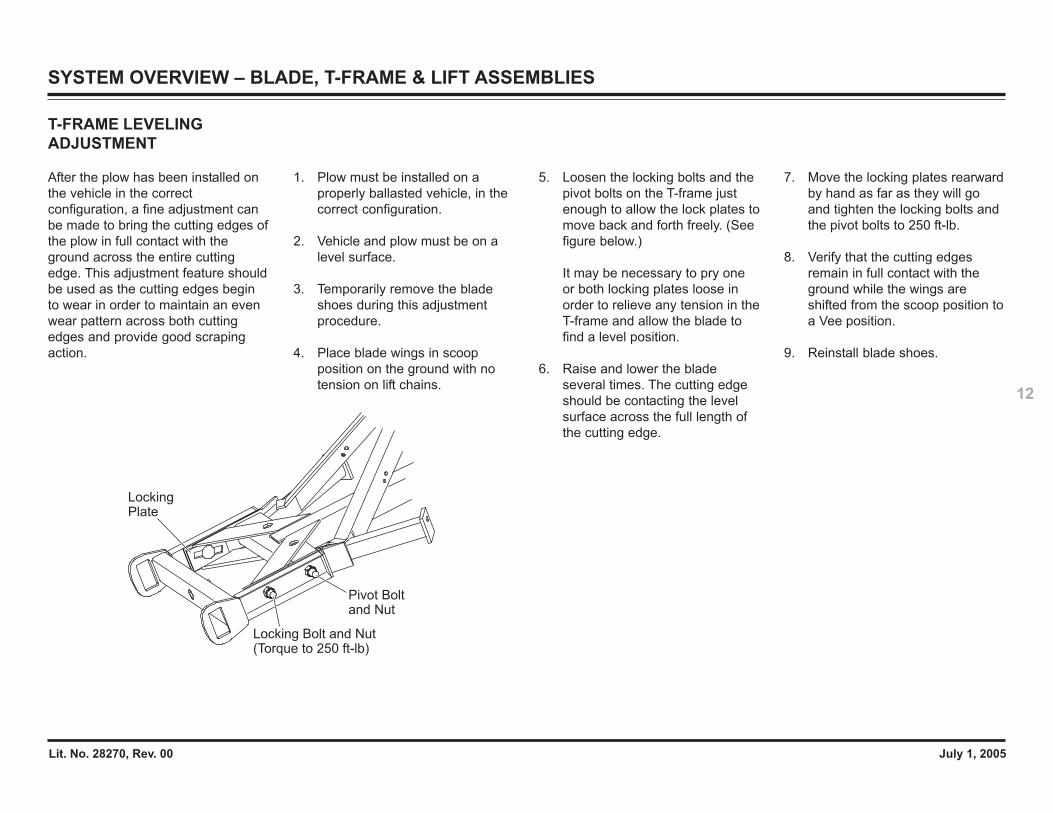
T-FRAME LEVELINGADJUSTMENT
After the plow has been installed onthe vehicle in the correctconfiguration, a fine adjustment canbe made to bring the cutting edges ofthe plow in full contact with theground across the entire cuttingedge. This adjustment feature shouldbe used as the cutting edges beginto wear in order to maintain an evenwear pattern across both cuttingedges and provide good scrapingaction.
1. Plow must be installed on aproperly ballasted vehicle, in thecorrect configuration.
2. Vehicle and plow must be on alevel surface.
3. Temporarily remove the bladeshoes during this adjustmentprocedure.
4. Place blade wings in scoopposition on the ground with notension on lift chains.
Locking Plate
Pivot Bolt and Nut
Locking Bolt and Nut(Torque to 250 ft-lb)
5. Loosen the locking bolts and thepivot bolts on the T-frame justenough to allow the lock plates tomove back and forth freely. (Seefigure below.)
It may be necessary to pry oneor both locking plates loose inorder to relieve any tension in theT-frame and allow the blade tofind a level position.
6. Raise and lower the bladeseveral times. The cutting edgeshould be contacting the levelsurface across the full length ofthe cutting edge.
7. Move the locking plates rearwardby hand as far as they will goand tighten the locking bolts andthe pivot bolts to 250 ft-lb.
8. Verify that the cutting edgesremain in full contact with theground while the wings areshifted from the scoop position toa Vee position.
9. Reinstall blade shoes.
SYSTEM OVERVIEW – BLADE, T-FRAME & LIFT ASSEMBLIES
Lit. No. 28270, Rev. 00 July 1, 2005
13
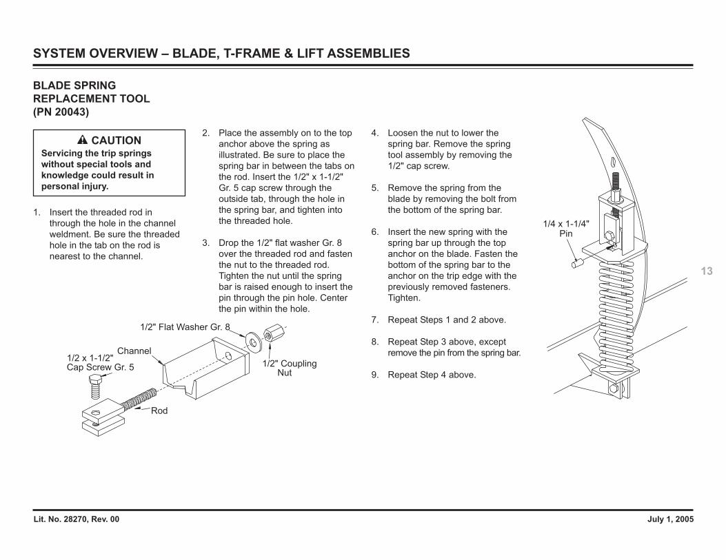
BLADE SPRINGREPLACEMENT TOOL(PN 20043)
1. Insert the threaded rod inthrough the hole in the channelweldment. Be sure the threadedhole in the tab on the rod isnearest to the channel.
CAUTIONServicing the trip springswithout special tools andknowledge could result inpersonal injury.
2. Place the assembly on to the topanchor above the spring asillustrated. Be sure to place thespring bar in between the tabs onthe rod. Insert the 1/2" x 1-1/2"Gr. 5 cap screw through theoutside tab, through the hole inthe spring bar, and tighten intothe threaded hole.
3. Drop the 1/2" flat washer Gr. 8over the threaded rod and fastenthe nut to the threaded rod.Tighten the nut until the springbar is raised enough to insert thepin through the pin hole. Centerthe pin within the hole.
4. Loosen the nut to lower thespring bar. Remove the springtool assembly by removing the1/2" cap screw.
5. Remove the spring from theblade by removing the bolt fromthe bottom of the spring bar.
6. Insert the new spring with thespring bar up through the topanchor on the blade. Fasten thebottom of the spring bar to theanchor on the trip edge with thepreviously removed fasteners.Tighten.
7. Repeat Steps 1 and 2 above.
8. Repeat Step 3 above, exceptremove the pin from the spring bar.
9. Repeat Step 4 above.
Channel
Rod
1/2 x 1-1/2"Cap Screw Gr. 5 1/2" Coupling
Nut
1/2" Flat Washer Gr. 8
1/4 x 1-1/4"Pin
SYSTEM OVERVIEW – BLADE, T-FRAME & LIFT ASSEMBLIES
Lit. No. 28270, Rev. 00 July 1, 2005
14
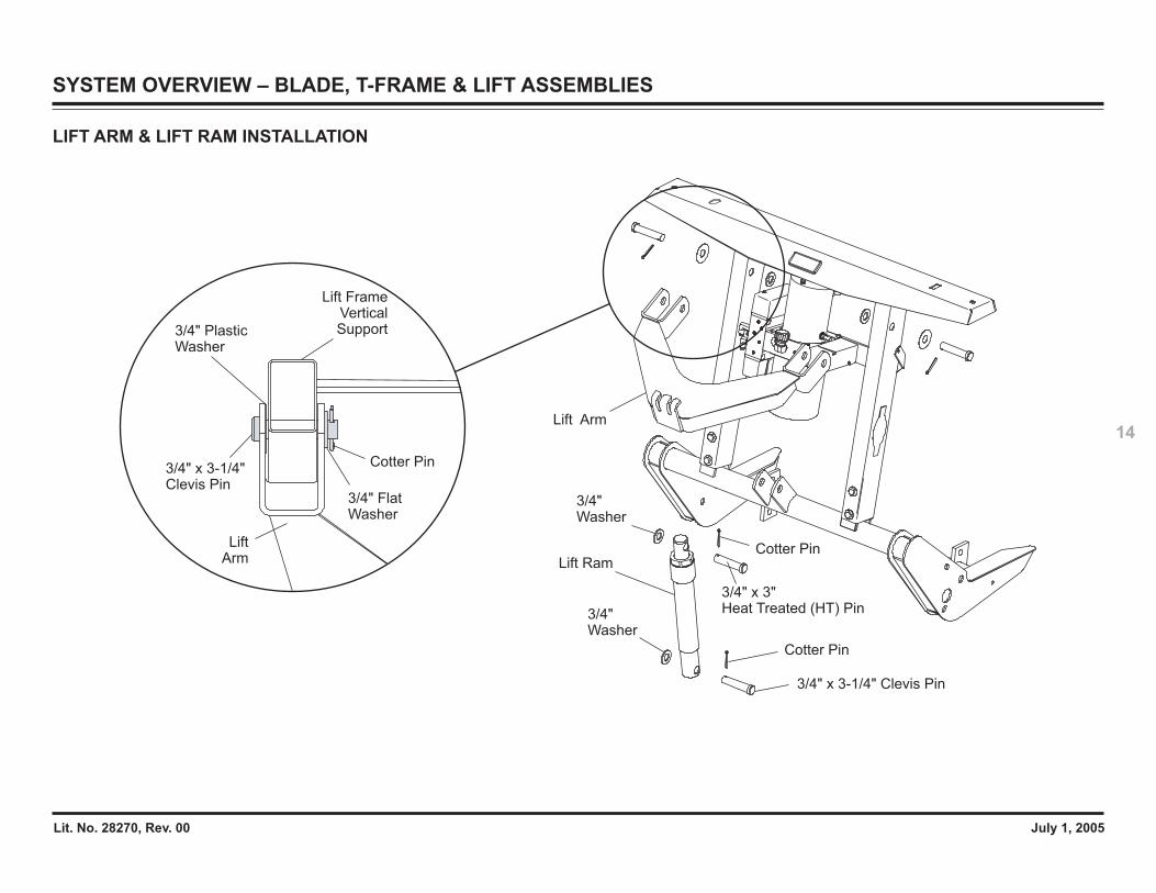
LIFT ARM & LIFT RAM INSTALLATION
Lift Arm
3/4" Flat Washer
Cotter Pin
LiftArm
Lift FrameVerticalSupport3/4" Plastic
Washer
3/4" x 3-1/4" Clevis Pin
3/4" x 3-1/4" Clevis Pin
3/4" x 3" Heat Treated (HT) Pin
3/4" Washer
Lift Ram
Cotter Pin
Cotter Pin
3/4" Washer
SYSTEM OVERVIEW – BLADE, T-FRAME & LIFT ASSEMBLIES

Lit. No. 28270, Rev. 00 July 1, 2005
15
VEHICLE LIGHTING CHECK
Check the operation of vehicle andplow lights with plow mounted tovehicle and all harnesses connected.
• Turn Signals and Parking Lamps
• Headlamps
• Daytime Running Lamps (DRLs)
• Joystick Control orCabCommand ControlThe control indicator light shouldlight whenever the controlON/OFF switch and the ignition(key) switches are both in theON Position. The snowplowelectrical plugs must beconnected to the vehicleelectrical plugs.
SYSTEM OVERVIEW – BLADE, T-FRAME & LIFT ASSEMBLIES
HEADLAMP BEAM AIMING
Torque headlamp fasteners to 45 ft-lbonce correct visual aim is achieved.
1. Place vehicle on a level surface25 feet in front of a matte-whitescreen, such as a garage door.The screen should beperpendicular both to the groundand to the vehicle centerline.
2. The vehicle should be equippedfor normal operation. Thesnowplow blade should be inplace and in raised position. Beloware steps listed by the Society ofAutomotive Engineers (SAE)pertinent to headlamp aiming inspecification #SAE J599d.
3. Prepare vehicle for headlampaim or inspection. Beforechecking beam aim, theinspector will:
a. Remove ice or mud fromunder fenders.
b. Set tire inflation pressures tothe values specified onvehicle information label.
c. Check springs for sag orbroken leaves.
d. See that there is no load inthe vehicle other than thedriver and ballast as specifiedin the Selection List.
e. Check functioning of anyautomatic vehicle levelingsystems and specificmanufacturer’s instructionspertaining to vehiclepreparation for headlampaiming.
f. Clean lenses.g. Check for bulb burnout and
proper beam switching.h. Stabilize suspension by
rocking vehicle sideways.
4. Mark (or tape) the verticalcenterline of the snowplowheadlamps and the vertical
Vertical Centerline ahead of DS Snowplow Headlamp
Align with vehicle centerline.
Vertical Centerline ahead of PS Snowplow Headlamp
Screen Located 25 Feet from SnowplowHeadlamps
Horizontal Centerline of Snowplow Headlamps
High Intensity Zones of Snowplow Headlamps on Low Beam
centerline of the vehicle on thescreen. Mark the horizontalcenterline of the snowplowheadlamps on the screen(distance from ground to snow-plow headlamp centers).
5. Align the top edge of the highintensity zone of the snowplowlower beam below the horizontalcenterline and the left edge ofthe high intensity zone on thevertical centerline for eachsnowplow headlamp. (Refer todiagram below.)
Lit. No. 28270, Rev. 00 July 1, 2005
16
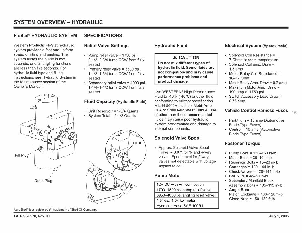
FloStat® HYDRAULIC SYSTEM
Western Products’ FloStat hydraulicsystem provides a fast and uniformspeed of lifting and angling. Thesystem raises the blade in twoseconds, and all angling functionsare less than five seconds. Forhydraulic fluid type and fillinginstructions, see Hydraulic System inthe Maintenance section of theOwner’s Manual.
Drain Plug
Fill Plug
12V DC with +/– connection 1700–1800 psi pump relief valve 3950–4050 psi angling relief valve 4.5" dia. 1.04 kw motor Hydraulic Hose SAE 100R1
Quill
SYSTEM OVERVIEW – HYDRAULIC
SPECIFICATIONS
Relief Valve Settings
• Pump relief valve = 1750 psi.2-1/2–2-3/4 turns CCW from fullyseated
• Primary relief valve = 3500 psi.1-1/2–1-3/4 turns CCW from fullyseated
• Secondary relief valve = 4000 psi.1-1/4–1-1/2 turns CCW from fullyseated
Fluid Capacity (Hydraulic Fluid)
• Unit Reservoir = 1-3/4 Quarts• System Total = 2-1/2 Quarts
CAUTIONDo not mix different types ofhydraulic fluid. Some fluids arenot compatible and may causeperformance problems andproduct damage.
Electrical System (Approximate)
• Solenoid Coil Resistance =7 Ohms at room temperature
• Solenoid Coil amp. Draw =1.5 amp
• Motor Relay Coil Resistance =16–17 Ohm
• Motor Relay Amp. Draw = 0.7 amp• Maximum Motor Amp. Draw =
190 amp at 1750 psi.• Switch Accessory Lead Draw =
0.75 amp
Vehicle Control Harness Fuses
• Park/Turn = 15 amp (AutomotiveBlade-Type Fuses)
• Control = 10 amp (AutomotiveBlade-Type Fuses)
Fastener Torque
• Pump Bolts = 150–160 in-lb• Motor Bolts = 30–40 in-lb• Reservoir Bolts = 15–20 in-lb• Cartridges = 120–144 in-lb• Check Valves = 120–144 in-lb• Coil Nuts = 48–60 in-lb• Secondary Manifold Block
Assembly Bolts = 105–115 in-lb• Angle Ram
Piston Locknuts = 100–120 ft-lbGland Nuts = 150–180 ft-lb
Hydraulic Fluid
Use WESTERN® High PerformanceFluid to -40°F (-40°C) or other fluidconforming to military specificationMIL-H-5606A, such as Mobil AeroHFA or Shell AeroShell® Fluid 4. Useof other than these recommendedfluids may cause poor hydraulicsystem performance and damage tointernal components.
Solenoid Valve Spool
• Approx. Solenoid Valve SpoolTravel = 0.07" for 3- and 4-wayvalves. Spool travel for 2-wayvalves not detectable with voltageapplied to coil.
Pump Motor
AeroShell® is a registered (®) trademark of Shell Oil Company.
Lit. No. 28270, Rev. 00 July 1, 2005
17
Use the following procedure toinstall hydraulic hoses.
1. Screw flare nut onto fitting flareand hand tighten.
2. Align hose so there are no twistsor sharp bends.
3. Using two wrenches, hold thehose in position and tighten flarenut 1/8 to 1/4 turn beyond handtight. Final torque on the flare nutshould be approximately 20 ft-lb.
SYSTEM OVERVIEW – HYDRAULIC
HYDRAULIC FITTING ANDHOSE INSTALLATION
NOTE: Overtightening JIC hosefitting ends will result in afractured fitting.
Do not use any type of sealant ortape on the fittings or hoses. Thiscould damage product. Always usetwo wrenches to ensure propertightening of fittings and hoses.
Use the following procedure toinstall SAE O-ring fittings in valveblock and rams.
1. Turn jam nut on fitting as far backas possible.
2. Lubricate O-ring with cleanhydraulic fluid.
3. Screw fitting into port by handuntil the washer contacts portface and shoulder of the jam nutthreads.
4. Unscrew fitting to proper positionno more than one full turn.
5. Using two wrenches, hold fittingbody in position and tighten jamnut until the washer againcontacts port face, then tightenan additional 1/8 to 1/4 turn tolock fitting in place. Final torqueon the jam nut should beapproximately 20 ft-lb.
Lit. No. 28270, Rev. 00 July 1, 2005
18
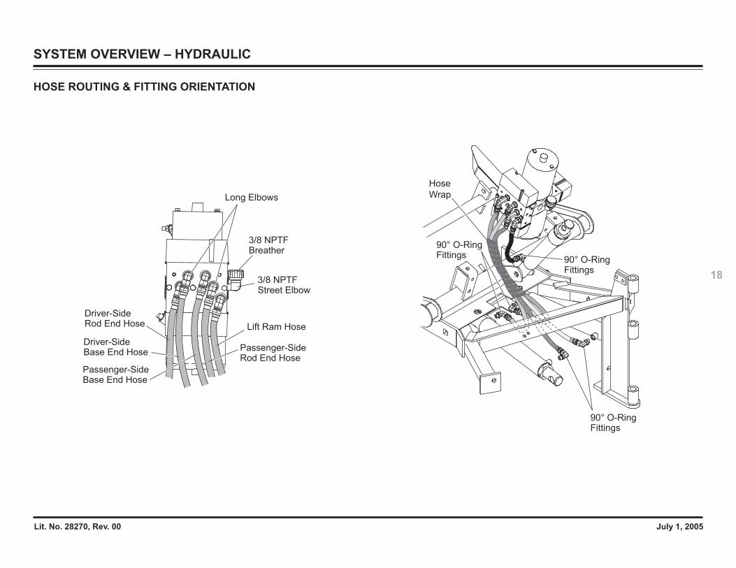
HOSE ROUTING & FITTING ORIENTATION
90° O-Ring Fittings
90° O-Ring Fittings
90° O-Ring Fittings
Hose
Wrap
SYSTEM OVERVIEW – HYDRAULIC
Lift Ram Hose
Driver-SideBase End Hose
Driver-SideRod End Hose
3/8 NPTF Street Elbow
3/8 NPTF Breather
Long Elbows
Passenger-SideBase End Hose
Passenger-SideRod End Hose

Lit. No. 28270, Rev. 00 July 1, 2005
19
Pump Relief Valve
Motor
Quill
Secondary Valve Block
Pilot-Operated Check Valve
Primary Valve Block
Solenoid Valve Cartridge
Solenoid Valve Coil
Pump Filter
Reservoir
StandoffScrew
Magnet
Pump
PumpShaftSeal
Return Screen Assembly
Retainer Clip
Pickup Tube
Breather and Elbow
Angle Ram Relief Valves
ASSEMBLY
SYSTEM OVERVIEW – HYDRAULIC
Lit. No. 28270, Rev. 00 July 1, 2005
20
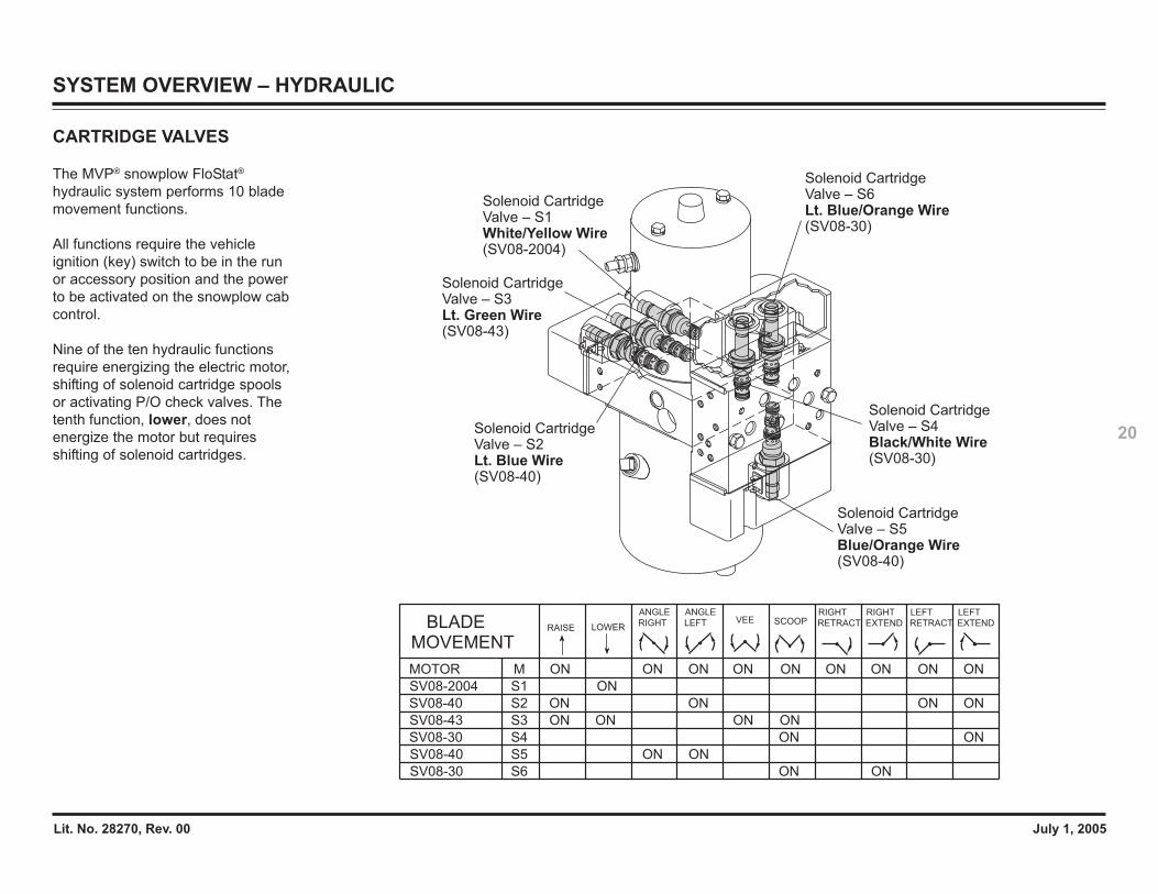
CARTRIDGE VALVES
The MVP® snowplow FloStat®
hydraulic system performs 10 blademovement functions.
All functions require the vehicleignition (key) switch to be in the runor accessory position and the powerto be activated on the snowplow cabcontrol.
Nine of the ten hydraulic functionsrequire energizing the electric motor,shifting of solenoid cartridge spoolsor activating P/O check valves. Thetenth function, lower, does notenergize the motor but requiresshifting of solenoid cartridges.
Solenoid CartridgeValve – S1White/Yellow Wire(SV08-2004)
Solenoid CartridgeValve – S3Lt. Green Wire(SV08-43)
Solenoid CartridgeValve – S2Lt. Blue Wire(SV08-40)
Solenoid CartridgeValve – S6Lt. Blue/Orange Wire(SV08-30)
Solenoid CartridgeValve – S4Black/White Wire(SV08-30)
Solenoid CartridgeValve – S5Blue/Orange Wire(SV08-40)
SV08-43 S3 ON ONON ON
SV08-2004 S1 ON
MOVEMENTBLADE RAISE LOWER
SCOOPVEE
SV08-30 S6 ON ON
RIGHT
EXTEND
RIGHT
RETRACT
LEFT
RETRACT EXTEND
LEFT
S4SV08-30 ON ON
SV08-40 S2 ON ON ONON
SV08-40 S5 ON ON
MOTOR M ONONON ON ON ON ONON ON
ANGLE
RIGHT
ANGLE
LEFT
SYSTEM OVERVIEW – HYDRAULIC
Lit. No. 28270, Rev. 00 July 1, 2005
21
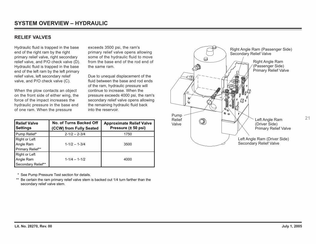
RELIEF VALVES
Hydraulic fluid is trapped in the baseend of the right ram by the rightprimary relief valve, right secondaryrelief valve, and P/O check valve (D).Hydraulic fluid is trapped in the baseend of the left ram by the left primaryrelief valve, left secondary reliefvalve, and P/O check valve (C).
When the plow contacts an objecton the front side of either wing, theforce of the impact increases thehydraulic pressure in the base endof one ram. When the pressure
Pump ReliefValve
Right Angle Ram (Passenger Side)Secondary Relief Valve
Right Angle Ram (Passenger Side)Primary Relief Valve
Left Angle Ram(Driver Side)Primary Relief Valve
Left Angle Ram (Driver Side)Secondary Relief Valve
Relief Valve Settings
No. of Turns Backed Off (CCW) from Fully Seated
Approximate Relief Valve Pressure (± 50 psi)
Pump Relief* 2-1/2 – 2-3/4 1750 Right or Left Angle Ram Primary Relief**
1-1/2 – 1-3/4 3500
Right or Left Angle Ram Secondary Relief**
1-1/4 – 1-1/2 4000
* See Pump Pressure Test section for details. ** Be certain the ram primary relief valve stem is backed out 1/4 turn farther than the
secondary relief valve stem.
exceeds 3500 psi, the ram'sprimary relief valve opens allowingsome of the hydraulic fluid to movefrom the base end of the rod end ofthe same ram.
Due to unequal displacement of thefluid between the base and rod endsof the ram, hydraulic pressure willcontinue to increase. When thepressure exceeds 4000 psi, the ram'ssecondary relief valve opens allowingthe remaining hydraulic fluid backinto the reservoir.
SYSTEM OVERVIEW – HYDRAULIC
Lit. No. 28270, Rev. 00 July 1, 2005
22
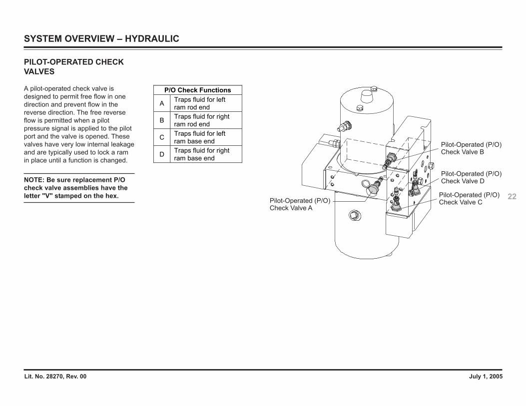
PILOT-OPERATED CHECKVALVES
A pilot-operated check valve isdesigned to permit free flow in onedirection and prevent flow in thereverse direction. The free reverseflow is permitted when a pilotpressure signal is applied to the pilotport and the valve is opened. Thesevalves have very low internal leakageand are typically used to lock a ramin place until a function is changed.
NOTE: Be sure replacement P/Ocheck valve assemblies have theletter "V" stamped on the hex.
Pilot-Operated (P/O)Check Valve A
Pilot-Operated (P/O)Check Valve D
Pilot-Operated (P/O)Check Valve C
Pilot-Operated (P/O)Check Valve B
P/O Check Functions
A Traps fluid for left ram rod end
B Traps fluid for right ram rod end
C Traps fluid for left ram base end
D Traps fluid for right ram base end
SYSTEM OVERVIEW – HYDRAULIC
Lit. No. 28270, Rev. 00 July 1, 2005
23
SYSTEM OVERVIEW – HYDRAULIC
Yellow Seal
Black Inner Backing Ring
Double-ActingRams Only
Single- and Double-Acting
Rams
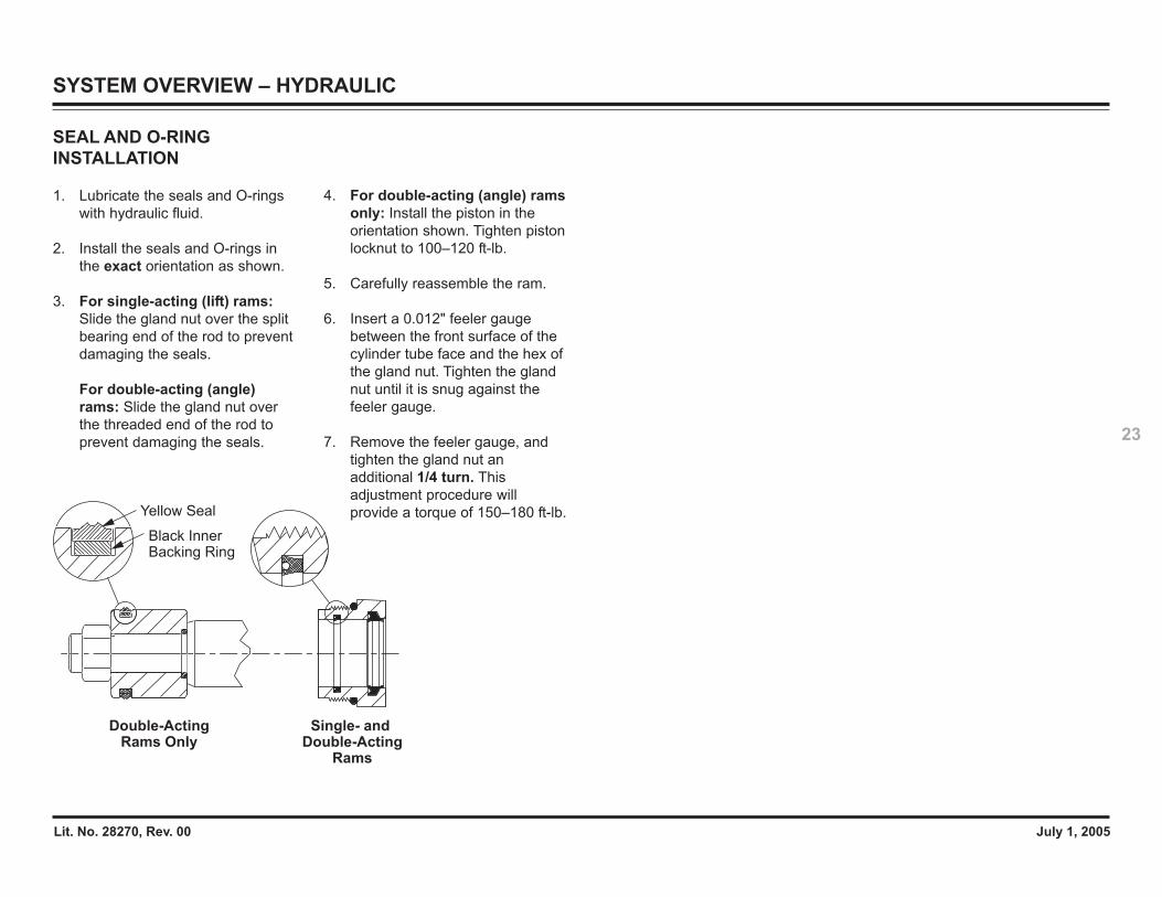
SEAL AND O-RINGINSTALLATION
1. Lubricate the seals and O-ringswith hydraulic fluid.
2. Install the seals and O-rings inthe exact orientation as shown.
3. For single-acting (lift) rams:Slide the gland nut over the splitbearing end of the rod to preventdamaging the seals.
For double-acting (angle)rams: Slide the gland nut overthe threaded end of the rod toprevent damaging the seals.
4. For double-acting (angle) ramsonly: Install the piston in theorientation shown. Tighten pistonlocknut to 100–120 ft-lb.
5. Carefully reassemble the ram.
6. Insert a 0.012" feeler gaugebetween the front surface of thecylinder tube face and the hex ofthe gland nut. Tighten the glandnut until it is snug against thefeeler gauge.
7. Remove the feeler gauge, andtighten the gland nut anadditional 1/4 turn. Thisadjustment procedure willprovide a torque of 150–180 ft-lb.
Lit. No. 28270, Rev. 00 July 1, 2005
24
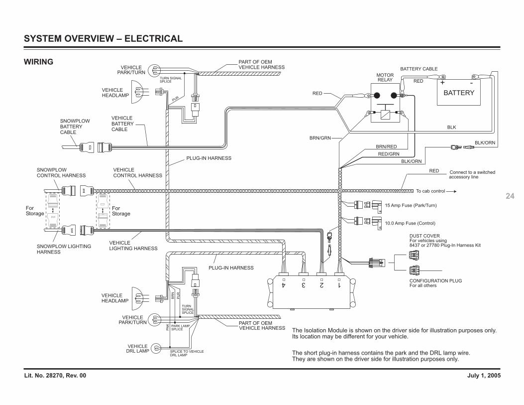
WIRING
124 3
VEHICLEHEADLAMP
VEHICLEHEADLAMP
TURN SIGNALSPLICE
PUR
MOTOR RELAY
PART OF OEMVEHICLE HARNESS BATTERY CABLE
RED
VEHICLE
CABLEBATTERY
RED
BATTERY
+ -
VEHICLE LIGHTING HARNESS
VEHICLE CONTROL HARNESS
VEHICLEPARK/TURN
VEHICLE HARNESSPART OF OEM
VEHICLEPARK/TURN
RED Connect to a switched accessory line
BRN/RED
RED/GRN
For Storage
PLUG-IN HARNESS
PLUG-IN HARNESSBLK/ORN
BLK/ORN
BLK
TURNSIGNALSPLICE
PU
R
The short plug-in harness contains the park and the DRL lamp wire. They are shown on the driver side for illustration purposes only.
The Isolation Module is shown on the driver side for illustration purposes only.Its location may be different for your vehicle.
BR
N
SNOWPLOW LIGHTINGHARNESS
SNOWPLOWCONTROL HARNESS
PN
K
SPLICE TO VEHICLEDRL LAMP
VEHICLE DRL LAMP
PARK LAMPSPLICE
DUST COVERFor vehicles using8437 or 27780 Plug-In Harness Kit
CONFIGURATION PLUGFor all others
15 Amp Fuse (Park/Turn)
10.0 Amp Fuse (Control)
BRN/GRN
To cab control
For Storage
SNOWPLOWBATTERYCABLE
SYSTEM OVERVIEW – ELECTRICAL
Lit. No. 28270, Rev. 00 July 1, 2005
25
SYSTEM OVERVIEW – CONTROLS
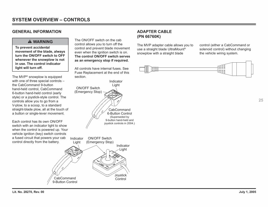
GENERAL INFORMATION
The MVP® snowplow is equippedwith one of three special controls –the CabCommand 9-buttonhand-held control, CabCommand6-button hand-held control (earlystyle) or a joystick-style control. Thecontrols allow you to go from aV-plow, to a scoop, to a standardstraight-blade plow, all at the touch ofa button or single-lever movement.
Each control has its own ON/OFFswitch with an indicator light to showwhen the control is powered up. Yourvehicle ignition (key) switch controlsa fused circuit that powers your cabcontrol directly from the battery.
RAISE
LOWER
PWR
RI
G
H
T
L
E
F
T
ON/OFF Switch (Emergency Stop)
ON/OFF Switch (Emergency Stop)
Indicator Light
Indicator Light
Indicator Light
CabCommand
9-Button Control
Joystick Control
CabCommand 6-Button Control
(Superseded by
9-button hand-held and
joystick controls in 2004.)
The ON/OFF switch on the cabcontrol allows you to turn off thecontrol and prevent blade movementeven when the ignition switch is on.The control ON/OFF switch servesas an emergency stop if required.
All controls have internal fuses. SeeFuse Replacement at the end of thissection.
WARNINGTo prevent accidentalmovement of the blade, alwaysturn the ON/OFF switch to OFFwhenever the snowplow is notin use. The control indicatorlight will turn off.
ADAPTER CABLE(PN 66760K)
The MVP adapter cable allows you touse a straight blade UltraMount®
snowplow with a straight blade
control (either a CabCommand orsolenoid control) without changingthe vehicle wiring system.
Lit. No. 28270, Rev. 00 July 1, 2005
26
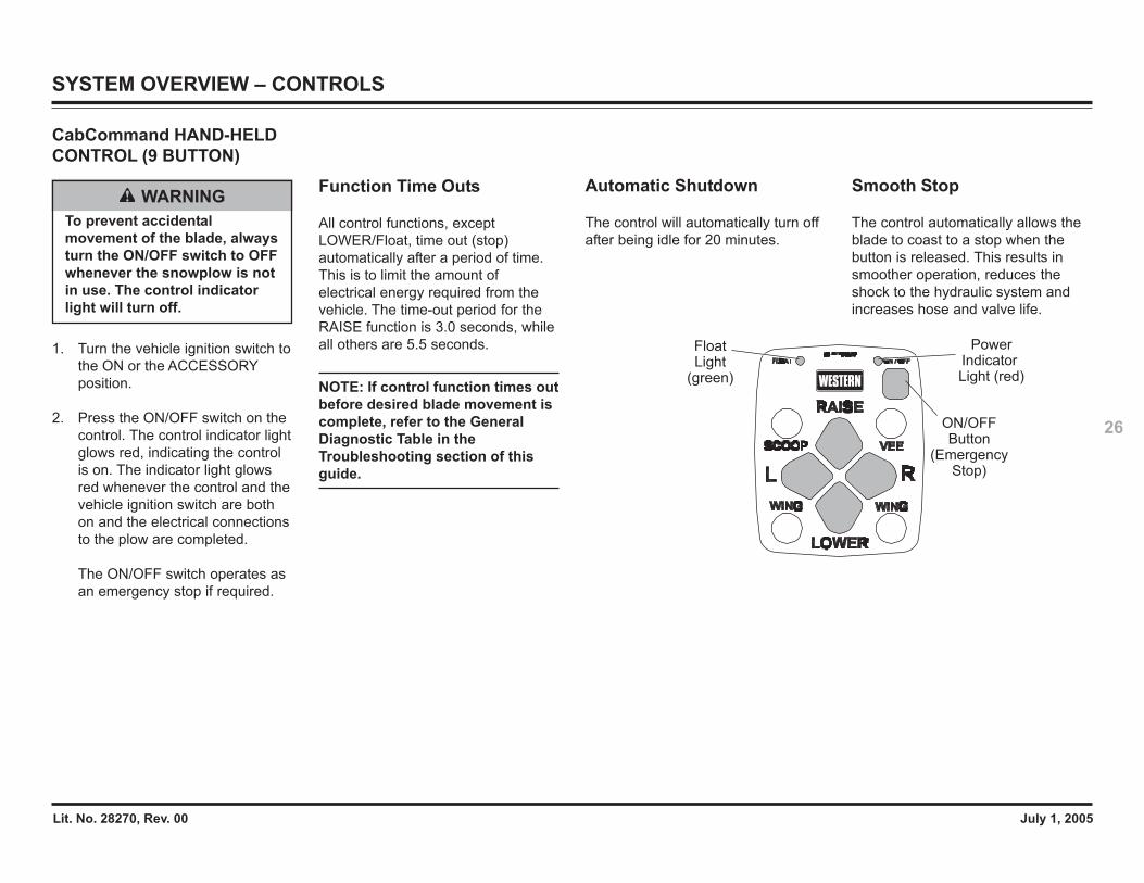
CabCommand HAND-HELDCONTROL (9 BUTTON)
1. Turn the vehicle ignition switch tothe ON or the ACCESSORYposition.
2. Press the ON/OFF switch on thecontrol. The control indicator lightglows red, indicating the controlis on. The indicator light glowsred whenever the control and thevehicle ignition switch are bothon and the electrical connectionsto the plow are completed.
The ON/OFF switch operates asan emergency stop if required.
WARNINGTo prevent accidentalmovement of the blade, alwaysturn the ON/OFF switch to OFFwhenever the snowplow is notin use. The control indicatorlight will turn off.
Function Time Outs
All control functions, exceptLOWER/Float, time out (stop)automatically after a period of time.This is to limit the amount ofelectrical energy required from thevehicle. The time-out period for theRAISE function is 3.0 seconds, whileall others are 5.5 seconds.
NOTE: If control function times outbefore desired blade movement iscomplete, refer to the GeneralDiagnostic Table in theTroubleshooting section of thisguide.
Power Indicator Light (red)
ON/OFFButton
(EmergencyStop)
Float Light
(green)
Automatic Shutdown
The control will automatically turn offafter being idle for 20 minutes.
Smooth Stop
The control automatically allows theblade to coast to a stop when thebutton is released. This results insmoother operation, reduces theshock to the hydraulic system andincreases hose and valve life.
SYSTEM OVERVIEW – CONTROLS
Lit. No. 28270, Rev. 00 July 1, 2005
27
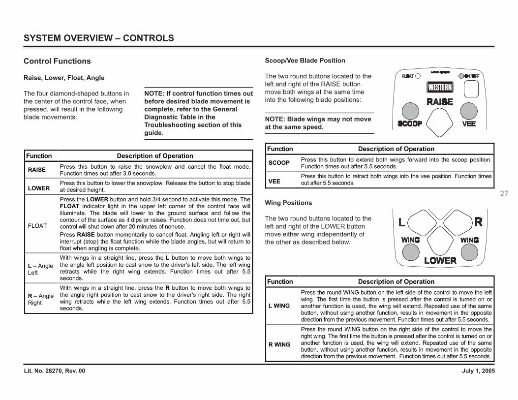
Scoop/Vee Blade Position
The two round buttons located to theleft and right of the RAISE buttonmove both wings at the same timeinto the following blade positions:
NOTE: Blade wings may not moveat the same speed.
Wing Positions
The two round buttons located to theleft and right of the LOWER buttonmove either wing independently ofthe other as described below.
Function Description of Operation
SCOOP Press this button to extend both wings forward into the scoop position. Function times out after 5.5 seconds.
VEE Press this button to retract both wings into the vee position. Function times out after 5.5 seconds.
Function Description of Operation
L WING
Press the round WING button on the left side of the control to move the left wing. The first time the button is pressed after the control is turned on or another function is used, the wing will extend. Repeated use of the same button, without using another function, results in movement in the opposite direction from the previous movement. Function times out after 5.5 seconds.
R WING
Press the round WING button on the right side of the control to move the right wing. The first time the button is pressed after the control is turned on or another function is used, the wing will extend. Repeated use of the same button, without using another function, results in movement in the opposite direction from the previous movement. Function times out after 5.5 seconds.
Control Functions
Raise, Lower, Float, Angle
The four diamond-shaped buttons inthe center of the control face, whenpressed, will result in the followingblade movements:
Function Description of Operation
RAISE Press this button to raise the snowplow and cancel the float mode. Function times out after 3.0 seconds.
LOWER Press this button to lower the snowplow. Release the button to stop blade at desired height.
FLOAT
Press the LOWER button and hold 3/4 second to activate this mode. The FLOAT indicator light in the upper left corner of the control face will illuminate. The blade will lower to the ground surface and follow the contour of the surface as it dips or raises. Function does not time out, but control will shut down after 20 minutes of nonuse. Press RAISE button momentarily to cancel float. Angling left or right will interrupt (stop) the float function while the blade angles, but will return to float when angling is complete.
L – Angle Left
With wings in a straight line, press the L button to move both wings to the angle left position to cast snow to the driver's left side. The left wing retracts while the right wing extends. Function times out after 5.5 seconds.
R – Angle Right
With wings in a straight line, press the R button to move both wings to the angle right position to cast snow to the driver's right side. The right wing retracts while the left wing extends. Function times out after 5.5 seconds.
NOTE: If control function times outbefore desired blade movement iscomplete, refer to the GeneralDiagnostic Table in theTroubleshooting section of thisguide.
SYSTEM OVERVIEW – CONTROLS
Lit. No. 28270, Rev. 00 July 1, 2005
28
WARNINGTo prevent accidentalmovement of the blade, alwaysturn the ON/OFF switch to OFFwhenever the snowplow is notin use. The control indicatorlight will turn off.
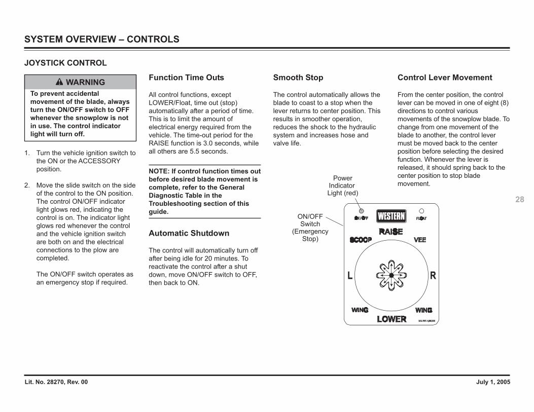
JOYSTICK CONTROL
1. Turn the vehicle ignition switch tothe ON or the ACCESSORYposition.
2. Move the slide switch on the sideof the control to the ON position.The control ON/OFF indicatorlight glows red, indicating thecontrol is on. The indicator lightglows red whenever the controland the vehicle ignition switchare both on and the electricalconnections to the plow arecompleted.
The ON/OFF switch operates asan emergency stop if required.
Function Time Outs
All control functions, exceptLOWER/Float, time out (stop)automatically after a period of time.This is to limit the amount ofelectrical energy required from thevehicle. The time-out period for theRAISE function is 3.0 seconds, whileall others are 5.5 seconds.
NOTE: If control function times outbefore desired blade movement iscomplete, refer to the GeneralDiagnostic Table in theTroubleshooting section of thisguide.
Automatic Shutdown
The control will automatically turn offafter being idle for 20 minutes. Toreactivate the control after a shutdown, move ON/OFF switch to OFF,then back to ON.
Smooth Stop
The control automatically allows theblade to coast to a stop when thelever returns to center position. Thisresults in smoother operation,reduces the shock to the hydraulicsystem and increases hose andvalve life.
Power Indicator Light (red)
ON/OFFSwitch
(EmergencyStop)
Control Lever Movement
From the center position, the controllever can be moved in one of eight (8)directions to control variousmovements of the snowplow blade. Tochange from one movement of theblade to another, the control levermust be moved back to the centerposition before selecting the desiredfunction. Whenever the lever isreleased, it should spring back to thecenter position to stop blademovement.
SYSTEM OVERVIEW – CONTROLS
Lit. No. 28270, Rev. 00 July 1, 2005
29
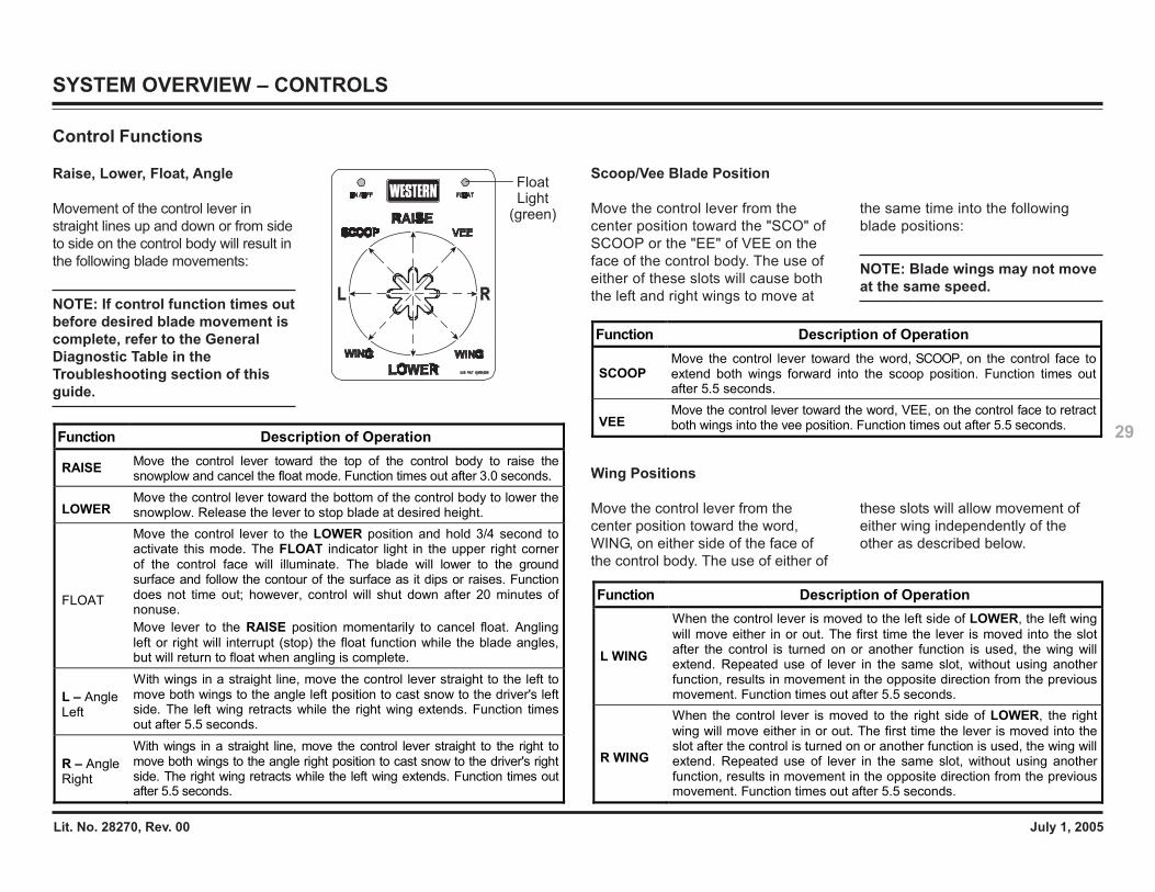
Scoop/Vee Blade Position
Move the control lever from thecenter position toward the "SCO" ofSCOOP or the "EE" of VEE on theface of the control body. The use ofeither of these slots will cause boththe left and right wings to move at
Function Description of Operation
SCOOP Move the control lever toward the word, SCOOP, on the control face to extend both wings forward into the scoop position. Function times out after 5.5 seconds.
VEE Move the control lever toward the word, VEE, on the control face to retract both wings into the vee position. Function times out after 5.5 seconds.
Function Description of Operation
L WING
When the control lever is moved to the left side of LOWER, the left wing will move either in or out. The first time the lever is moved into the slot after the control is turned on or another function is used, the wing will extend. Repeated use of lever in the same slot, without using another function, results in movement in the opposite direction from the previous movement. Function times out after 5.5 seconds.
R WING
When the control lever is moved to the right side of LOWER, the right wing will move either in or out. The first time the lever is moved into the slot after the control is turned on or another function is used, the wing will extend. Repeated use of lever in the same slot, without using another function, results in movement in the opposite direction from the previous movement. Function times out after 5.5 seconds.
Function Description of Operation
RAISE Move the control lever toward the top of the control body to raise the snowplow and cancel the float mode. Function times out after 3.0 seconds.
LOWER Move the control lever toward the bottom of the control body to lower the snowplow. Release the lever to stop blade at desired height.
FLOAT
Move the control lever to the LOWER position and hold 3/4 second to activate this mode. The FLOAT indicator light in the upper right corner of the control face will illuminate. The blade will lower to the ground surface and follow the contour of the surface as it dips or raises. Function does not time out; however, control will shut down after 20 minutes of nonuse. Move lever to the RAISE position momentarily to cancel float. Angling left or right will interrupt (stop) the float function while the blade angles, but will return to float when angling is complete.
L – Angle Left
With wings in a straight line, move the control lever straight to the left to move both wings to the angle left position to cast snow to the driver's left side. The left wing retracts while the right wing extends. Function times out after 5.5 seconds.
R – Angle Right
With wings in a straight line, move the control lever straight to the right to move both wings to the angle right position to cast snow to the driver's right side. The right wing retracts while the left wing extends. Function times out after 5.5 seconds.
Float Light
(green)
Control Functions
Raise, Lower, Float, Angle
Movement of the control lever instraight lines up and down or from sideto side on the control body will result inthe following blade movements:
NOTE: If control function times outbefore desired blade movement iscomplete, refer to the GeneralDiagnostic Table in theTroubleshooting section of thisguide.
the same time into the followingblade positions:
NOTE: Blade wings may not moveat the same speed.
Wing Positions
Move the control lever from thecenter position toward the word,WING, on either side of the face ofthe control body. The use of either of
these slots will allow movement ofeither wing independently of theother as described below.
SYSTEM OVERVIEW – CONTROLS
Lit. No. 28270, Rev. 00 July 1, 2005
30
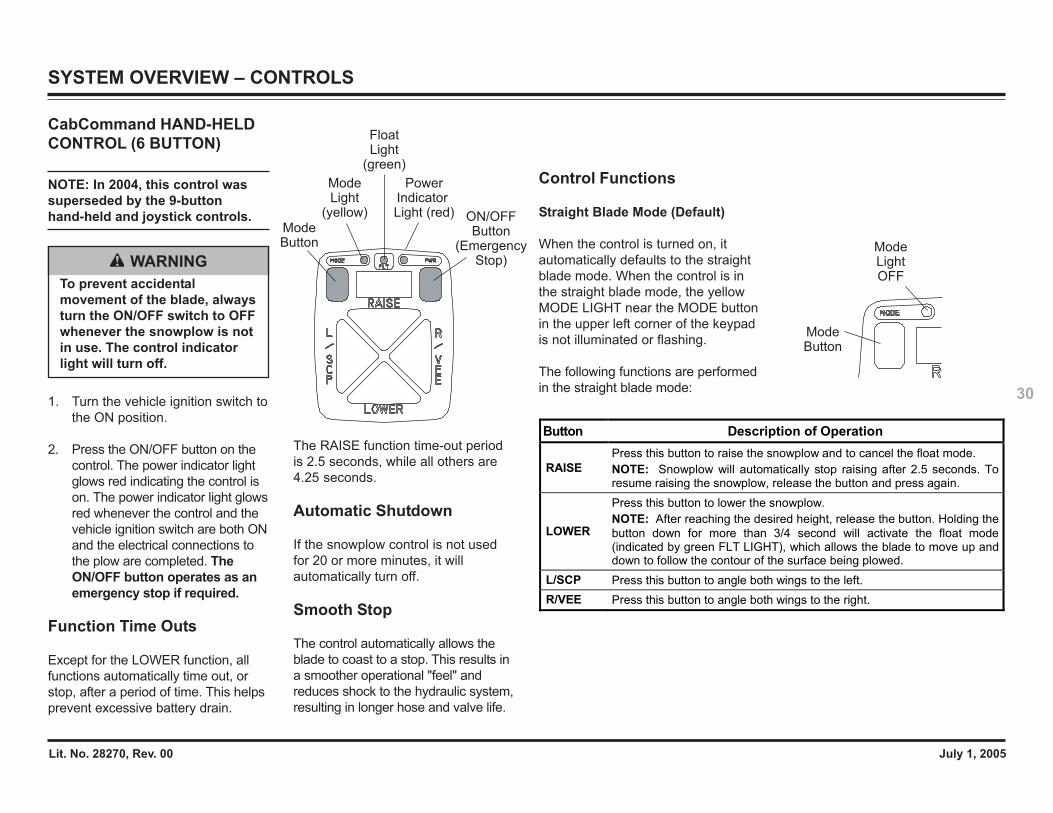
CabCommand HAND-HELDCONTROL (6 BUTTON)
NOTE: In 2004, this control wassuperseded by the 9-buttonhand-held and joystick controls.
1. Turn the vehicle ignition switch tothe ON position.
2. Press the ON/OFF button on thecontrol. The power indicator lightglows red indicating the control ison. The power indicator light glowsred whenever the control and thevehicle ignition switch are both ONand the electrical connections tothe plow are completed. TheON/OFF button operates as anemergency stop if required.
Function Time Outs
Except for the LOWER function, allfunctions automatically time out, orstop, after a period of time. This helpsprevent excessive battery drain.
WARNINGTo prevent accidentalmovement of the blade, alwaysturn the ON/OFF switch to OFFwhenever the snowplow is notin use. The control indicatorlight will turn off.
The RAISE function time-out periodis 2.5 seconds, while all others are4.25 seconds.
Automatic Shutdown
If the snowplow control is not usedfor 20 or more minutes, it willautomatically turn off.
Smooth Stop
The control automatically allows theblade to coast to a stop. This results ina smoother operational "feel" andreduces shock to the hydraulic system,resulting in longer hose and valve life.
Power Indicator Light (red) ON/OFF
Button(Emergency
Stop)
Float Light
(green)
Mode Light
(yellow)Mode Button
Control Functions
Straight Blade Mode (Default)
When the control is turned on, itautomatically defaults to the straightblade mode. When the control is inthe straight blade mode, the yellowMODE LIGHT near the MODE buttonin the upper left corner of the keypadis not illuminated or flashing.
The following functions are performedin the straight blade mode:
Button Description of Operation
RAISE Press this button to raise the snowplow and to cancel the float mode. NOTE: Snowplow will automatically stop raising after 2.5 seconds. To resume raising the snowplow, release the button and press again.
LOWER
Press this button to lower the snowplow. NOTE: After reaching the desired height, release the button. Holding the button down for more than 3/4 second will activate the float mode (indicated by green FLT LIGHT), which allows the blade to move up and down to follow the contour of the surface being plowed.
L/SCP Press this button to angle both wings to the left. R/VEE Press this button to angle both wings to the right.
Mode Light OFF
Mode Button
SYSTEM OVERVIEW – CONTROLS
Lit. No. 28270, Rev. 00 July 1, 2005
31Button Description of Operation
RAISE Press this button to raise the snowplow and to cancel the float mode. NOTE: Snowplow will automatically stop raising after 2.5 seconds. To resume raising the snowplow, release the button and press again.
LOWER
Press this button to lower the snowplow. NOTE: After reaching the desired height, release the button. Holding the button down for more than 3/4 second will activate the float mode (indicated by green FLT LIGHT), which allows the blade to move up and down to follow the contour of the surface being plowed.
L/SCP Press this button to extend both wings to the scoop position. R/VEE Press this button to retract both wings to the vee position.
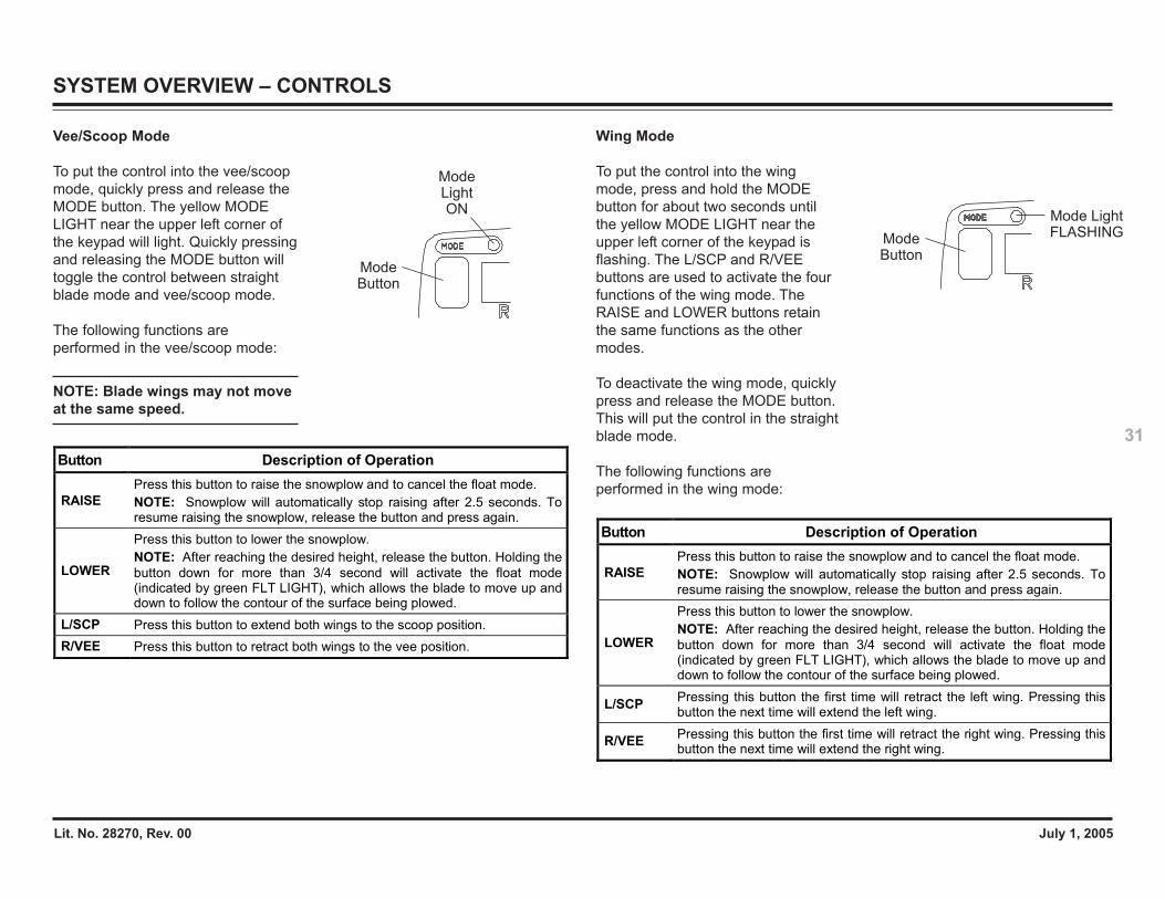
Vee/Scoop Mode
To put the control into the vee/scoopmode, quickly press and release theMODE button. The yellow MODELIGHT near the upper left corner ofthe keypad will light. Quickly pressingand releasing the MODE button willtoggle the control between straightblade mode and vee/scoop mode.
The following functions areperformed in the vee/scoop mode:
NOTE: Blade wings may not moveat the same speed.
Mode Light ON
Mode Button
Wing Mode
To put the control into the wingmode, press and hold the MODEbutton for about two seconds untilthe yellow MODE LIGHT near theupper left corner of the keypad isflashing. The L/SCP and R/VEEbuttons are used to activate the fourfunctions of the wing mode. TheRAISE and LOWER buttons retainthe same functions as the othermodes.
To deactivate the wing mode, quicklypress and release the MODE button.This will put the control in the straightblade mode.
The following functions areperformed in the wing mode:
Button Description of Operation
RAISE Press this button to raise the snowplow and to cancel the float mode. NOTE: Snowplow will automatically stop raising after 2.5 seconds. To resume raising the snowplow, release the button and press again.
LOWER
Press this button to lower the snowplow. NOTE: After reaching the desired height, release the button. Holding the button down for more than 3/4 second will activate the float mode (indicated by green FLT LIGHT), which allows the blade to move up and down to follow the contour of the surface being plowed.
L/SCP Pressing this button the first time will retract the left wing. Pressing this button the next time will extend the left wing.
R/VEE Pressing this button the first time will retract the right wing. Pressing this button the next time will extend the right wing.
Mode Light FLASHINGMode
Button
SYSTEM OVERVIEW – CONTROLS
Lit. No. 28270, Rev. 00 July 1, 2005
32
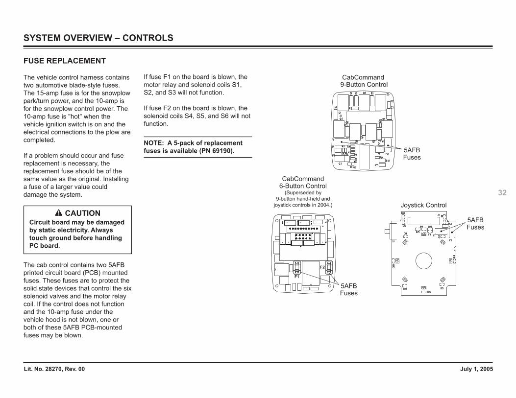
FUSE REPLACEMENT
The vehicle control harness containstwo automotive blade-style fuses.The 15-amp fuse is for the snowplowpark/turn power, and the 10-amp isfor the snowplow control power. The10-amp fuse is "hot" when thevehicle ignition switch is on and theelectrical connections to the plow arecompleted.
If a problem should occur and fusereplacement is necessary, thereplacement fuse should be of thesame value as the original. Installinga fuse of a larger value coulddamage the system.
The cab control contains two 5AFBprinted circuit board (PCB) mountedfuses. These fuses are to protect thesolid state devices that control the sixsolenoid valves and the motor relaycoil. If the control does not functionand the 10-amp fuse under thevehicle hood is not blown, one orboth of these 5AFB PCB-mountedfuses may be blown.
If fuse F1 on the board is blown, themotor relay and solenoid coils S1,S2, and S3 will not function.
If fuse F2 on the board is blown, thesolenoid coils S4, S5, and S6 will notfunction.
NOTE: A 5-pack of replacementfuses is available (PN 69190).
CAUTIONCircuit board may be damagedby static electricity. Alwaystouch ground before handlingPC board.
5AFB Fuses
Joystick Control
5AFB Fuses
CabCommand 9-Button Control
F1
F2
5AFB Fuses
CabCommand 6-Button Control
(Superseded by
9-button hand-held and
joystick controls in 2004.)
SYSTEM OVERVIEW – CONTROLS
Lit. No. 28270, Rev. 00 July 1, 2005
33
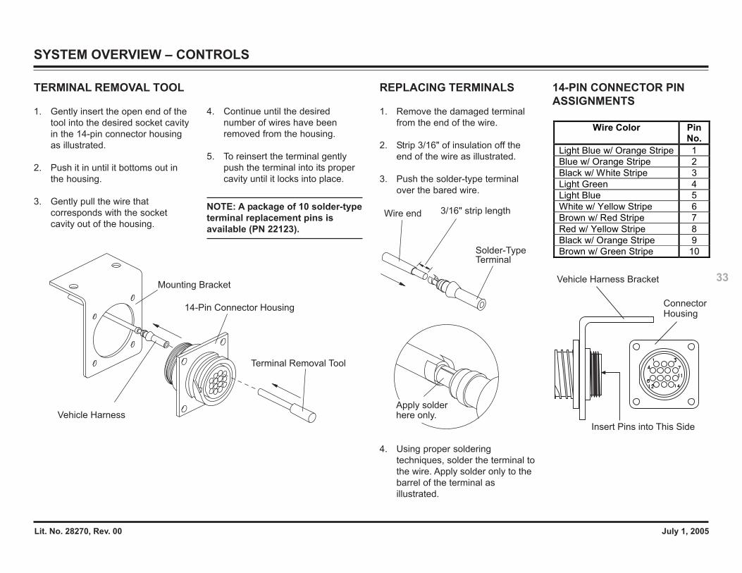
TERMINAL REMOVAL TOOL
1. Gently insert the open end of thetool into the desired socket cavityin the 14-pin connector housingas illustrated.
2. Push it in until it bottoms out inthe housing.
3. Gently pull the wire thatcorresponds with the socketcavity out of the housing.
4. Continue until the desirednumber of wires have beenremoved from the housing.
5. To reinsert the terminal gentlypush the terminal into its propercavity until it locks into place.
NOTE: A package of 10 solder-typeterminal replacement pins isavailable (PN 22123).
REPLACING TERMINALS
1. Remove the damaged terminalfrom the end of the wire.
2. Strip 3/16" of insulation off theend of the wire as illustrated.
3. Push the solder-type terminalover the bared wire.
4. Using proper solderingtechniques, solder the terminal tothe wire. Apply solder only to thebarrel of the terminal asillustrated.
Terminal Removal Tool
14-Pin Connector Housing
Mounting Bracket
Vehicle Harness
3/16" strip lengthWire end
Solder-TypeTerminal
Apply solderhere only.
SYSTEM OVERVIEW – CONTROLS
Wire Color Pin No.
Light Blue w/ Orange Stripe 1 Blue w/ Orange Stripe 2 Black w/ White Stripe 3 Light Green 4 Light Blue 5 White w/ Yellow Stripe 6 Brown w/ Red Stripe 7 Red w/ Yellow Stripe 8 Black w/ Orange Stripe 9 Brown w/ Green Stripe 10
14-PIN CONNECTOR PINASSIGNMENTS
Insert Pins into This Side
Vehicle Harness Bracket
ConnectorHousing
Lit. No. 28270, Rev. 00 July 1, 2005
34
THEORY OF OPERATION
SNOWPLOW HEADLAMPS
The Isolation Module acts as anelectrical hub, automatically directingvehicle power to the appropriatevehicle or snowplow lighting devices,while also supplying battery power tothe snowplow control.
The vehicle high and low beamsenter and exit the Isolation Modulethrough positions 3 (left-side lighting)and position 4 (right-side lighting).Park, turn, and DRL signals alsoenter through positions 3 and 4.
When the snowplow is not attachedto the vehicle, the signal passesthrough the normally closed relaycontacts to the vehicle headlamps.During this time, the Isolation Moduleis inactive, placing no current drawon the vehicle's electrical system.
With the snowplow attached, theIsolation Module is still inactive untileither of the two following conditionsare met: the vehicle parking lights areturned on or the vehicle ignitionswitch is turned on.
Turning on the vehicle parking lightsactivates a series of relays,automatically transferring the vehiclehigh and low beams to the snowplowwhile supplying battery power directlyto the snowplow parking lights. Allsnowplow lighting exits the IsolationModule through position 2.
Turning on the vehicle ignition switchenergizes a snowplow control relay,supplying vehicle battery powerdirectly to the control via the vehiclecontrol harness. The vehicle ignitionswitch also supplies power to thevehicle turn signals. Activating thevehicle turn signals energizes turnsignal relays, which supply vehiclebattery power directly to thesnowplow turn signals.
SNOWPLOW DAYTIMERUNNING LIGHTS
Because Daytime Running Lamps(DRLs) are controlled differently onsome vehicles, two Isolation Moduleshave been developed.
The standard Isolation Moduletransfers the DRL output to thesnowplow lights when the vehicleignition switch is on and thesnowplow is attached.
When the Isolation Module designedfor vehicles with dedicated DRLbulbs senses the vehicle in the DRLmode, a series of relays energize,placing the snowplow high beams inseries. This Isolation Module doesnot turn off the vehicle DRLs.
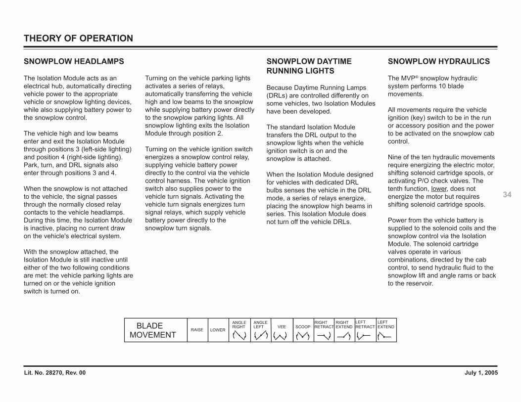
SNOWPLOW HYDRAULICS
The MVP® snowplow hydraulicsystem performs 10 blademovements.
All movements require the vehicleignition (key) switch to be in the runor accessory position and the powerto be activated on the snowplow cabcontrol.
Nine of the ten hydraulic movementsrequire energizing the electric motor,shifting solenoid cartridge spools, oractivating P/O check valves. Thetenth function, lower, does notenergize the motor but requiresshifting solenoid cartridge spools.
Power from the vehicle battery issupplied to the solenoid coils and thesnowplow control via the IsolationModule. The solenoid cartridgevalves operate in variouscombinations, directed by the cabcontrol, to send hydraulic fluid to thesnowplow lift and angle rams or backto the reservoir.
MOVEMENTBLADE
RAISE LOWER
ANGLERIGHT
ANGLELEFT
RIGHTEXTEND
RIGHTRETRACT
LEFTRETRACTSCOOPVEE EXTEND
LEFT
Lit. No. 28270, Rev. 00 July 1, 2005
35
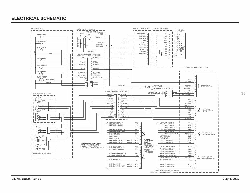
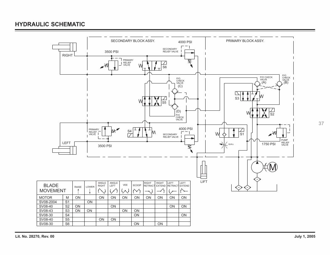
ELECTRICAL & HYDRAULIC SCHEMATICS
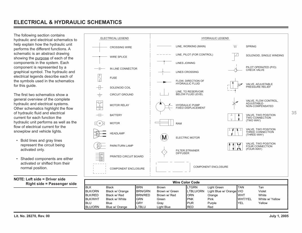
The following section containshydraulic and electrical schematics tohelp explain how the hydraulic unitperforms the different functions. Aschematic is an abstract drawingshowing the purpose of each of thecomponents in the system. Eachcomponent is represented by agraphical symbol. The hydraulic andelectrical legends describe each ofthe symbols used in the schematicsfor this guide.
The first two schematics show ageneral overview of the completehydraulic and electrical systems.Other schematics highlight the flowof hydraulic fluid and electricalcurrent for each function thehydraulic unit performs as well as theflow of electrical current for thesnowplow and vehicle lights.
• Bold lines and gray linesrepresent the circuit beingactivated only.
• Shaded components are eitheractivated or shifted from theirnormal position.
NOTE: Left side = Driver sideRight side = Passenger side
FILTER,STRAINERDIFFUSER
COMPONENT ENCLOSURE
ELECTRIC MOTOR
RAM
HYDRAULIC PUMPFIXED DISPLACEMENT
LINE, TO RESERVOIRBELOW FLUID LEVEL
LINES CROSSING
LINES JOINING
LINE, PILOT (FOR CONTROL)
LINE, WORKING (MAIN)
FLOW, DIRECTION OFHYDRAULIC FLUID
SOLENOID, SINGLE WINDING
SPRING
VALVE, ADJUSTABLEPRESSURE RELIEF
VALVE, FLOW CONTROL,ADJUSTABLE-NON-COMPENSATED
VALVE, TWO POSITIONTWO CONNECTION(TWO WAY)
VALVE, TWO POSITIONTHREE CONNECTION(THREE-WAY)
VALVE, TWO POSITIONFOUR CONNECTION(FOUR-WAY)
HYDRAULIC LEGEND
PILOT OPERATED (P/O)CHECK VALVE
CROSSING WIRE
WIRE SPLICE
FUSE
SOLENOID COIL
CIRCUIT GROUND
MOTOR RELAY
BATTERY
MOTOR
ELECTRICAL LEGEND
IN LINE CONNECTOR
PARK/TURN LAMP
M +–
COMPONENT ENCLOSURE
PRINTED CIRCUIT BOARD
L
HHEADLAMP
Wire Color Code BLK Black BRN Brown LTGRN Light Green TAN Tan BLK/ORN Black w/ Orange BRN/GRN Brown w/ Green LTBLU/ORN Light Blue w/ Orange VIO Violet BLK/RED Black w/ Red BRN/RED Brown w/ Red ORN Orange WHT White BLK/WHT Black w/ White GRN Green PNK Pink WHT/YEL White w/ Yellow BLU Blue GRY Gray PUR Purple YEL Yellow BLU/ORN Blue w/ Orange LTBLU Light Blue RED Red
Lit. No. 28270, Rev. 00 July 1, 2005
36
ELECTRICAL SCHEMATIC
BLU/ORG
LT BLU
BRN
GRY
PUR
BLK/WHT
WHT/YEL
BLK/ORG
BLK
WHT
DK BLU/WHT
BLU/RED
BLU
RED/WHT
RED/BLK
RED
YEL*A
A
C
B
E
G
F
H
J
K
D
A
C
B
E
G
F
H
J
K
D
LT BLU
BLU*
PUR
WHT/YEL
ORG
RED
GRN
GRN
YEL*
LT BLU
BLU*
BRN
PUR
WHT/YEL
ORG
RED
GRN
GRN
A
C
B
E
G
F
H
J
K
D
C
B
E
G
F
H
J
K
D
TO SWITCHED ACCESSORY LEAD
12
V B
AT
TE
RY
#6 BLK
BRN/RED
BRN/GRN
#6 RED
CONFIGURATION PLUG OR DUST COVER PLUG
PLOW ASSEMBLY LOCATED NEAR BATTERY
MTR RLY
#6 RED
LOCATED AT FRONT OF VEHICLE
LT BLU
LT GRN
WHT/YEL
LT BLU
LT GRN
WHT/YEL
#6 BLK
#6 RED From Vehicle Control Harness
From Vehicle Lighting Harness
From Left Side Vehicle Headlamps
From Right Side Vehicle Headlamps4
3
2
1
FOR HB-3/HB-4 HEADLAMPS:TO VEHICLE HEADLAMPS,PARK/TURN, DRL, ANDFACTORY VEHICLE HARNESSES
RIGHT COMMON OUT
RIGHT COMMON IN
RIGHT TURN IN
RIGHT LOW BEAM OUT
RIGHT HIGH BEAM OUT
RIGHT HIGH BEAM IN
RIGHT LOW BEAM IN
LEFT COMMON OUT
LEFT COMMON IN
PARK LAMP IN
LEFT TURN IN
DRL SIGNAL IN
LEFT LOW BEAM OUT
LEFT HIGH BEAM OUT
LEFT HIGH BEAM IN
LEFT LOW BEAM IN YEL
PUR
ORN
RED
GRN
YEL
LT BLU (or BLU)
BLU (or LT BLU)
LT BLU (or BLU)
BLU (or LT BLU)
BRN
PUR
PNK
ORN
RED
GRNA
C
B
E
G
F
H
D
A
C
B
E
G
F
H
D
J
K
J
KRIGHT COMMON OUT
RIGHT COMMON IN
RIGHT TURN IN
RIGHT HIGH BEAM 2 OUT**
RIGHT LOW BEAM OUT
RIGHT HIGH BEAM OUT
RIGHT HIGH BEAM 2 IN**
RIGHT HIGH BEAM IN
RIGHT LOW BEAM IN
LEFT COMMON OUT
LEFT COMMON IN
PARK LAMP IN
LEFT TURN IN
LEFT HIGH BEAM 2 OUT**
LEFT LOW BEAM OUT
LEFT HIGH BEAM OUT
LEFT HIGH BEAM 2 IN **
LEFT HIGH BEAM IN
LEFT LOW BEAM IN
1
3
5
4
7
6
8
9
10
11
2
1
3
5
4
7
6
8
9
10
11
2
1
2
1
2
RIGHT SIDE PLOW LAMP
P
T
RED
BRN
RED
BRNP
T
L
H
LEFT SIDE PLOW LAMP
BRN
BRN
RED
RED
P
T
P
T
L
H
LT BLU/ORN
BLU/ORN
RED
BLK/WHT
LOCATED AT FRONT OF VEHICLE
BRN
PUR
GRY
WHT
BLK/ORN
LT BLU
BLK
WHT/YEL
BLK/ORN
BLK/WHT
BLU/ORN
BRN
PUR
GRY
WHT
BLU/ORN
LT BLU
WHT/YEL
BLK/ORN
BLK/WHT
BLK
BLK/ORN
1
3
5
4
7
6
8
9
10
11
2
1
3
2
5
7
6
8
9
10
11
4
S1 SOLENOID
S2 SOLENOID
PUMP MOTOR
#6 BLK
#6 BLK/RED- +M
S3 SOLENOID
S4 SOLENOID
S5 SOLENOID
S6 SOLENOID
RED
BLK/WHT
RED/YEL
BLU/ORN
LT BLU/ORN
HAND-HELDCONTROL
COIL CORD HARNESS
6
7
5
4WHT
BLK
GRN
ORN
2
3
1YEL
BLU
RED
6
4
3
5
2
1
3
4
6
5
7
2
1
7
8
9
10
11
12
13
14
8
9
10
11
8
9
10
11
VIO
GRY
TAN
BRN
LOCATED UNDER DASH
6
4
3
5
2
1
7
8
9
10
11
12
13
14
RED/YEL
BRN/GRN
LT BLU/ORN
BLU/ORN
BLK/WHT
LT GRN
LT BLU
WHT/YEL
BRN/RED
15-AMP P/T FUSE
10-AMP CONTROL FUSE
A
C
B
A
C
B
* HB-1 (9004) A= BLUE, J=YELLOW** 99–02 DODGE RAM W/ SPORT PACKAGE
BLK/ORN
RED/GRN
(Shown in
de-energized state)
4
3
RE
D
RED/GRN
RED/YEL
BLK/ORN
EXCEPT
FOR ALLHEADLAMPS
TO VEHICLE HEADLAMPS,PARK/TURN, AND FACTORYVEHICLEHARNESSES
HB-3/HB-4:
F1
F2
Lit. No. 28270, Rev. 00 July 1, 2005
37
HYDRAULIC SCHEMATIC
M
LEFT
RIGHT
3500 PSI
3500 PSI
4000 PSI
4000 PSI
1750 PSI
S6
S3
S1
S5
S4
S2
(C)
(D)
(A) (B)
LIFT
RELIEF VALVESECONDARY
RELIEF VALVESECONDARY
SECONDARY BLOCK ASSY. PRIMARY BLOCK ASSY.
VALVERELIEFPRIMARY
PRIMARYRELIEFVALVE
VALVERELIEFPUMP
P/O CHECKVALVE
P/O CHECKVALVE
P/O CHECKVALVE
P/O CHECKVALVE
QUILL
SV08-43 S3 ON ONON ON
SV08-2004 S1 ON
MOVEMENTBLADE RAISE LOWER
SCOOPVEE
SV08-30 S6 ON ON
RIGHT
EXTEND
RIGHT
RETRACT
LEFT
RETRACT EXTEND
LEFT
S4SV08-30 ON ON
SV08-40 S2 ON ON ONON
SV08-40 S5 ON ON
MOTOR M ONONON ON ON ON ONON ON
ANGLE
RIGHT
ANGLE
LEFT
Lit. No. 28270, Rev. 00 July 1, 2005
38
RAISE – ELECTRICAL
RED/WHT
RED
A
C
B
E
G
F
H
J
K
D
TO SWITCHED ACCESSORY LEAD1
2V
BA
TT
ER
Y
#6 BLK
BRN/RED
BRN/GRN
#6 RED
PLOW ASSEMBLY LOCATED NEAR BATTERY
MTR RLY
#6 RED
LOCATED AT FRONT OF VEHICLE
LT BLU
LT GRN
WHT/YEL
LT BLU
LT GRN
WHT/YEL
#6 BLK
#6 RED
From Vehicle Control Harness1
1
3
5
4
7
6
8
9
10
11
2
1
3
5
4
7
6
8
9
10
11
2
1
2
1
2
LT BLU/ORN
BLU/ORN
RED
BLK/WHT
S1 SOLENOID
S2 SOLENOID
PUMP MOTOR
#6 BLK
#6 BLK/RED- +M
S3 SOLENOID
S4 SOLENOID
S5 SOLENOID
S6 SOLENOID
RED
BLK/WHT
RED/YEL
BLU/ORN
LT BLU/ORN
HAND-HELDCONTROL
COIL CORD HARNESS
6
7
5
4WHT
BLK
GRN
ORN
2
3
1YEL
BLU
RED
6
4
3
5
2
1
3
4
6
5
7
2
1
7
8
9
10
11
12
13
14
8
9
10
11
8
9
10
11
VIO
GRY
TAN
BRN
LOCATED UNDER DASH
6
4
3
5
2
1
7
8
9
10
11
12
13
14
RED/YEL
BLK/ORN
BRN/GRN
LT BLU/ORN
BLU/ORN
BLK/WHT
LT GRN
LT BLU
WHT/YEL
BRN/RED
10-AMP CONTROL FUSE
BLK/ORN
RED/GRN
TO PIN 2 OF VEHICLE LIGHTING HARNESS
ISOLATION MODULE
RE
DB
LK
/OR
N
RED/YEL
TO PLOW P/T BULB GROUND
F1
F2
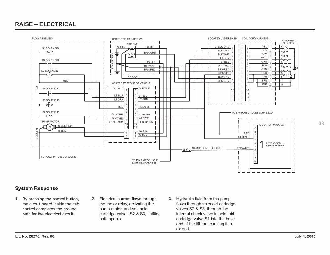
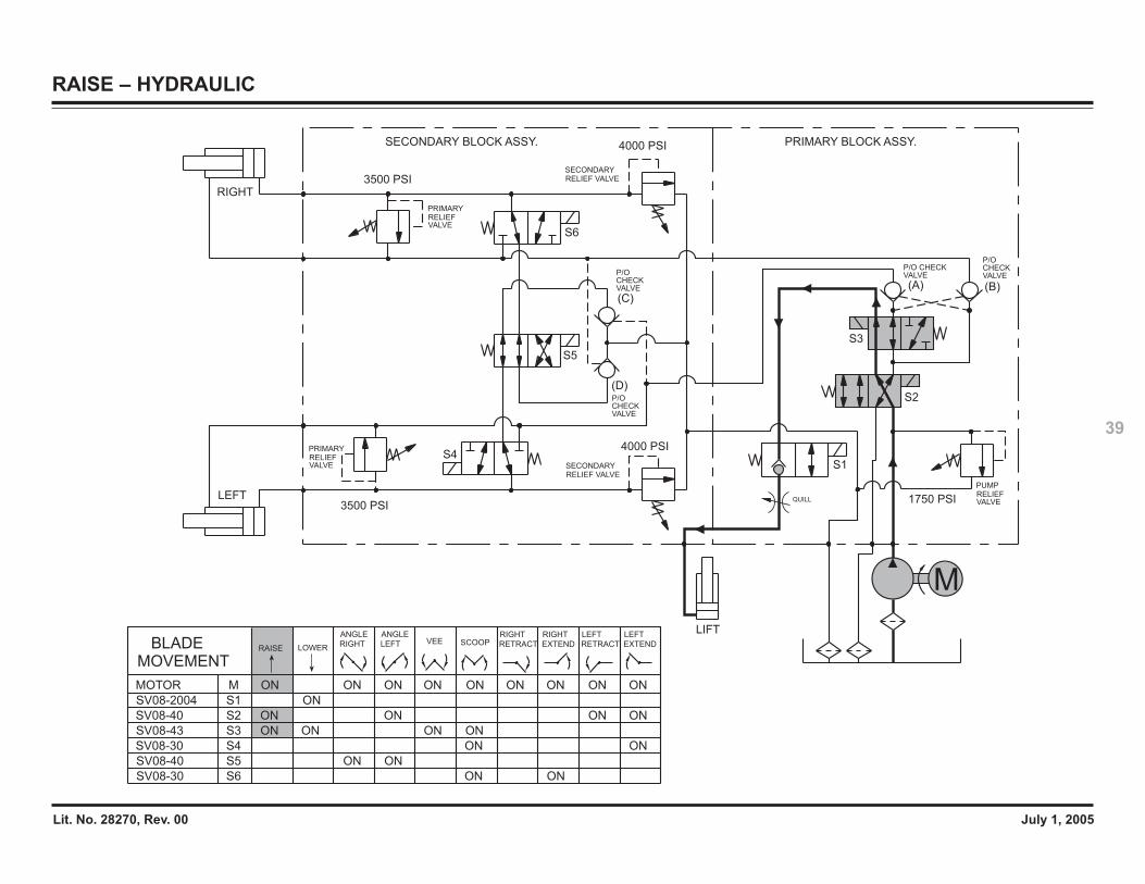
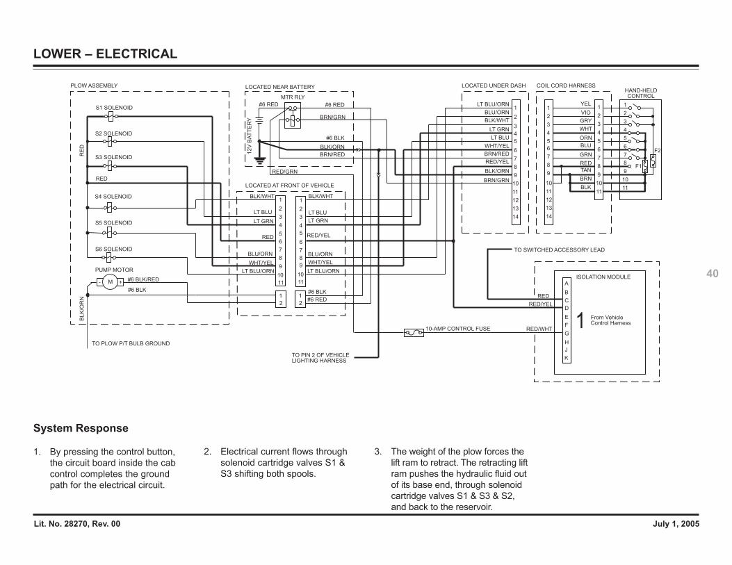
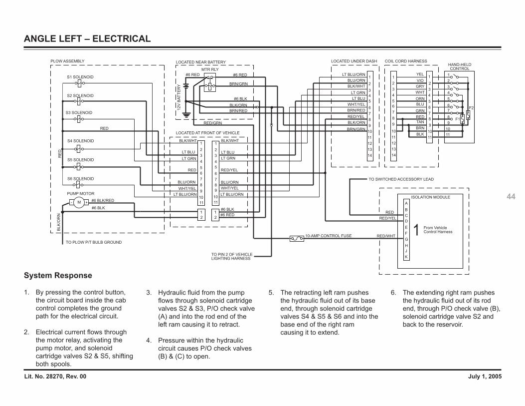
System Response
1. By pressing the control button,the circuit board inside the cabcontrol completes the groundpath for the electrical circuit.
2. Electrical current flows throughthe motor relay, activating thepump motor, and solenoidcartridge valves S2 & S3, shiftingboth spools.
3. Hydraulic fluid from the pumpflows through solenoid cartridgevalves S2 & S3, through theinternal check valve in solenoidcartridge valve S1 into the baseend of the lift ram causing it toextend.
Lit. No. 28270, Rev. 00 July 1, 2005
39
RAISE – HYDRAULIC
QUILLLEFT
RIGHT
3500 PSI
3500 PSI
4000 PSI
4000 PSI
1750 PSI
S6
S1
S5
S4
(C)
(D)
(A) (B)
LIFT
M
S3
S2
RELIEF VALVESECONDARY
RELIEF VALVESECONDARY
SECONDARY BLOCK ASSY. PRIMARY BLOCK ASSY.
VALVERELIEFPRIMARY
PRIMARYRELIEFVALVE
VALVERELIEFPUMP
P/O CHECKVALVE
P/O CHECKVALVEP/O
CHECKVALVE
P/O CHECKVALVE
SV08-43 S3 ON ONON ON
SV08-2004 S1 ON
MOVEMENTBLADE RAISE LOWER
SCOOPVEE
SV08-30 S6 ON ON
RIGHT
EXTEND
RIGHT
RETRACT
LEFT
RETRACT EXTEND
LEFT
S4SV08-30 ON ON
SV08-40 S2 ON ON ONON
SV08-40 S5 ON ON
MOTOR M ONONON ON ON ON ONON ON
ANGLE
RIGHT
ANGLE
LEFT
Lit. No. 28270, Rev. 00 July 1, 2005
40
LOWER – ELECTRICAL
RED
A
C
B
E
G
F
H
J
K
D
TO SWITCHED ACCESSORY LEAD1
2V
BA
TT
ER
Y
#6 BLK
BRN/RED
BRN/GRN
#6 RED
PLOW ASSEMBLY LOCATED NEAR BATTERY
MTR RLY
#6 RED
LOCATED AT FRONT OF VEHICLE
LT BLU
LT GRN
WHT/YEL
LT BLU
LT GRN
WHT/YEL
#6 BLK
#6 RED
From Vehicle Control Harness1
1
3
5
4
7
6
8
9
10
11
2
1
3
5
4
7
6
8
9
10
11
2
1
2
1
2
LT BLU/ORN
BLU/ORN
RED
BLK/WHT
S1 SOLENOID
S2 SOLENOID
PUMP MOTOR
#6 BLK
#6 BLK/RED- +M
S3 SOLENOID
S4 SOLENOID
S5 SOLENOID
S6 SOLENOID
RED
BLK/WHT
BLU/ORN
LT BLU/ORN
HAND-HELDCONTROL
COIL CORD HARNESS
6
7
5
4WHT
BLK
GRN
ORN
2
3
1YEL
BLU
RED
6
4
3
5
2
1
3
4
6
5
7
2
1
7
8
9
10
11
12
13
14
8
9
10
11
8
9
10
11
VIO
GRY
TAN
BRN
LOCATED UNDER DASH
6
4
3
5
2
1
7
8
9
10
11
12
13
14
BLK/ORN
BRN/GRN
LT BLU/ORN
BLU/ORN
BLK/WHT
LT GRN
LT BLU
WHT/YEL
BRN/RED
10-AMP CONTROL FUSE
BLK/ORN
RED/GRN
TO PIN 2 OF VEHICLE LIGHTING HARNESS
ISOLATION MODULE
RE
D
TO PLOW P/T BULB GROUND
BL
K/O
RN
RED/YEL
RED/WHT
RED/YEL
RED/YELF1
F2
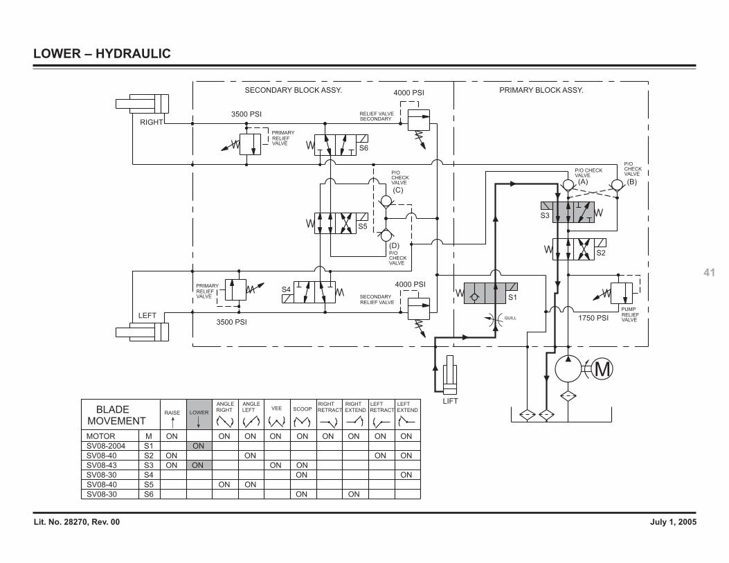
System Response
1. By pressing the control button,the circuit board inside the cabcontrol completes the groundpath for the electrical circuit.
2. Electrical current flows throughsolenoid cartridge valves S1 &S3 shifting both spools.
3. The weight of the plow forces thelift ram to retract. The retracting liftram pushes the hydraulic fluid outof its base end, through solenoidcartridge valves S1 & S3 & S2,and back to the reservoir.
Lit. No. 28270, Rev. 00 July 1, 2005
41
LOWER – HYDRAULIC
QUILL
M
LEFT
RIGHT
3500 PSI
3500 PSI
4000 PSI
4000 PSI
1750 PSI
S6
S5
S4
S2
(C)
(D)
(A) (B)
LIFT
S3
S1RELIEF VALVESECONDARY
RELIEF VALVESECONDARY
SECONDARY BLOCK ASSY. PRIMARY BLOCK ASSY.
VALVERELIEFPRIMARY
PRIMARYRELIEFVALVE
VALVERELIEFPUMP
P/O CHECKVALVE
P/O CHECKVALVE
P/O CHECKVALVE
P/O CHECKVALVE
SV08-43 S3 ON ONON ON
SV08-2004 S1 ON
MOVEMENTBLADE RAISE LOWER
SCOOPVEE
SV08-30 S6 ON ON
RIGHT
EXTEND
RIGHT
RETRACT
LEFT
RETRACT EXTEND
LEFT
S4SV08-30 ON ON
SV08-40 S2 ON ON ONON
SV08-40 S5 ON ON
MOTOR M ONONON ON ON ON ONON ON
ANGLE
RIGHT
ANGLE
LEFT
Lit. No. 28270, Rev. 00 July 1, 2005
42
ANGLE RIGHT – ELECTRICAL
TO PLOW P/T BULB GROUND
RED/WHT
RED/YEL
RED/YEL
RED/GRN
BLK
/OR
N RED/YEL
RED
A
C
B
E
G
F
H
J
K
D
TO SWITCHED ACCESSORY LEAD1
2V
BA
TT
ER
Y
#6 BLK
BRN/RED
BRN/GRN
#6 RED
PLOW ASSEMBLY LOCATED NEAR BATTERY
MTR RLY
#6 RED
LOCATED AT FRONT OF VEHICLE
LT BLU
LT GRN
WHT/YEL
LT BLU
LT GRN
WHT/YEL
#6 BLK
#6 RED
From Vehicle Control Harness1
1
3
5
4
7
6
8
9
10
11
2
1
3
5
4
7
6
8
9
10
11
2
1
2
1
2
LT BLU/ORN
BLU/ORN
RED
BLK/WHT
S1 SOLENOID
S2 SOLENOID
RE
D
PUMP MOTOR
#6 BLK
#6 BLK/RED- +M
S3 SOLENOID
S4 SOLENOID
S5 SOLENOID
S6 SOLENOID
RED
BLK/WHT
BLU/ORN
LT BLU/ORN
HAND-HELDCONTROL
COIL CORD HARNESS
6
7
5
4WHT
BLK
GRN
ORN
2
3
1YEL
BLU
RED
6
4
3
5
2
1
3
4
6
5
7
2
1
7
8
9
10
11
12
13
14
8
9
10
11
8
9
10
11
VIO
GRY
TAN
BRN
LOCATED UNDER DASH
6
4
3
5
2
1
7
8
9
10
11
12
13
14
BLK/ORN
BRN/GRN
LT BLU/ORN
BLU/ORN
BLK/WHT
LT GRN
LT BLU
WHT/YEL
BRN/RED
10-AMP CONTROL FUSE
BLK/ORN
TO PIN 2 OF VEHICLE LIGHTING HARNESS
ISOLATION MODULE
F1
F2
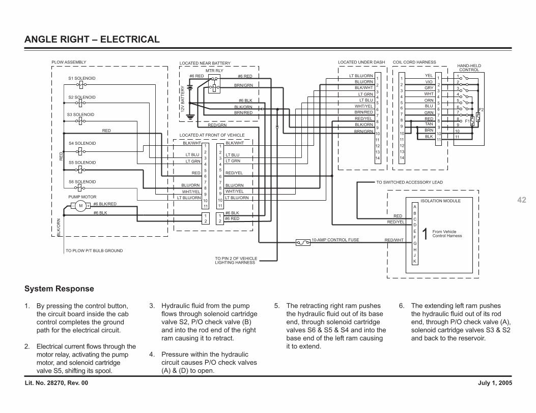
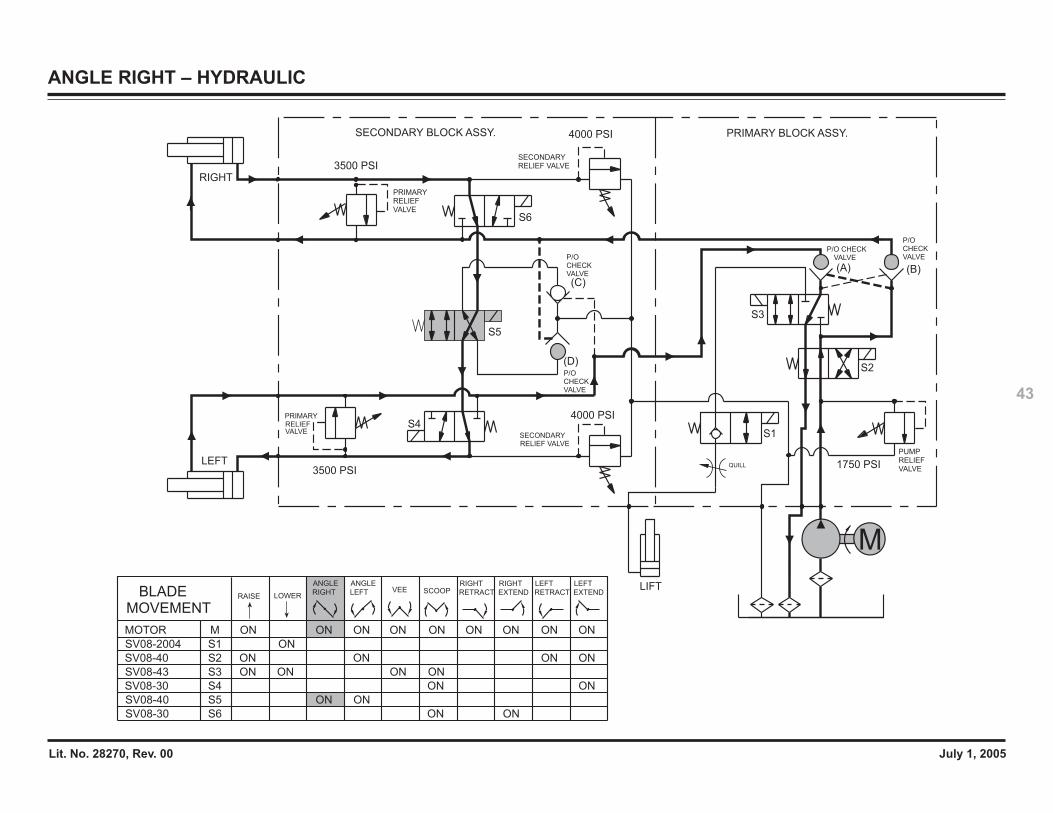
System Response
1. By pressing the control button,the circuit board inside the cabcontrol completes the groundpath for the electrical circuit.
2. Electrical current flows through themotor relay, activating the pumpmotor, and solenoid cartridgevalve S5, shifting its spool.
5. The retracting right ram pushesthe hydraulic fluid out of its baseend, through solenoid cartridgevalves S6 & S5 & S4 and into thebase end of the left ram causingit to extend.
6. The extending left ram pushesthe hydraulic fluid out of its rodend, through P/O check valve (A),solenoid cartridge valves S3 & S2and back to the reservoir.
3. Hydraulic fluid from the pumpflows through solenoid cartridgevalve S2, P/O check valve (B)and into the rod end of the rightram causing it to retract.
4. Pressure within the hydrauliccircuit causes P/O check valves(A) & (D) to open.
Lit. No. 28270, Rev. 00 July 1, 2005
43
ANGLE RIGHT – HYDRAULIC
LEFT
RIGHT
3500 PSI
3500 PSI
4000 PSI
4000 PSI
1750 PSI
S6
S3
S1S4
S2
(C)
(D)
(A) (B)
LIFT
M
S5
PRIMARYRELIEFVALVE
RELIEF VALVESECONDARY
VALVERELIEFPUMP
RELIEF VALVESECONDARY
SECONDARY BLOCK ASSY. PRIMARY BLOCK ASSY.
PRIMARYRELIEFVALVE
VALVECHECKP/O
VALVECHECKP/O
VALVECHECKP/O
VALVEP/O CHECK
QUILL
SV08-43 S3 ON ONON ON
SV08-2004 S1 ON
MOVEMENTBLADE RAISE LOWER
SCOOPVEE
SV08-30 S6 ON ON
RIGHT
EXTEND
RIGHT
RETRACT
LEFT
RETRACT EXTEND
LEFT
S4SV08-30 ON ON
SV08-40 S2 ON ON ONON
SV08-40 S5 ON ON
MOTOR M ONONON ON ON ON ONON ON
ANGLE
RIGHT
ANGLE
LEFT
Lit. No. 28270, Rev. 00 July 1, 2005
44
ANGLE LEFT – ELECTRICAL
RED
A
C
B
E
G
F
H
J
K
D
TO SWITCHED ACCESSORY LEAD1
2V
BA
TT
ER
Y
#6 BLK
BRN/RED
BRN/GRN
#6 RED
PLOW ASSEMBLY LOCATED NEAR BATTERY
MTR RLY
#6 RED
LOCATED AT FRONT OF VEHICLE
LT BLU
LT GRN
WHT/YEL
LT BLU
LT GRN
WHT/YEL
#6 BLK
#6 RED
From Vehicle Control Harness1
1
3
5
4
7
6
8
9
10
11
2
1
3
5
4
7
6
8
9
10
11
2
1
2
1
2
LT BLU/ORN
BLU/ORN
RED
BLK/WHT
S1 SOLENOID
S2 SOLENOID
RE
D
PUMP MOTOR
#6 BLK
#6 BLK/RED- +M
S3 SOLENOID
S4 SOLENOID
S5 SOLENOID
S6 SOLENOID
RED
BLK/WHT
BLU/ORN
LT BLU/ORN
HAND-HELDCONTROL
COIL CORD HARNESS
6
7
5
4WHT
BLK
GRN
ORN
2
3
1YEL
BLU
RED
6
4
3
5
2
1
3
4
6
5
7
2
1
7
8
9
10
11
12
13
14
8
9
10
11
8
9
10
11
VIO
GRY
TAN
BRN
LOCATED UNDER DASH
6
4
3
5
2
1
7
8
9
10
11
12
13
14
BLK/ORN
BRN/GRN
LT BLU/ORN
BLU/ORN
BLK/WHT
LT GRN
LT BLU
WHT/YEL
BRN/RED
10-AMP CONTROL FUSE
BLK/ORN
TO PIN 2 OF VEHICLE LIGHTING HARNESS
ISOLATION MODULE
RED/WHT
RED/YEL
RED/YEL
RED/GRN
BL
K/O
RN
RED/YEL
TO PLOW P/T BULB GROUND
F1
F2
System Response
1. By pressing the control button,the circuit board inside the cabcontrol completes the groundpath for the electrical circuit.
2. Electrical current flows throughthe motor relay, activating thepump motor, and solenoidcartridge valves S2 & S5, shiftingboth spools.
3. Hydraulic fluid from the pumpflows through solenoid cartridgevalves S2 & S3, P/O check valve(A) and into the rod end of theleft ram causing it to retract.
4. Pressure within the hydrauliccircuit causes P/O check valves(B) & (C) to open.
5. The retracting left ram pushesthe hydraulic fluid out of its baseend, through solenoid cartridgevalves S4 & S5 & S6 and into thebase end of the right ramcausing it to extend.
6. The extending right ram pushesthe hydraulic fluid out of its rodend, through P/O check valve (B),solenoid cartridge valve S2 andback to the reservoir.

Lit. No. 28270, Rev. 00 July 1, 2005
45
ANGLE LEFT – HYDRAULIC
QUILLLEFT
RIGHT
3500 PSI
3500 PSI
4000 PSI
4000 PSI
1750 PSI
S6
S3
S1S4
(C)
(D)
(A) (B)
LIFT
M
S5
S2
RELIEF VALVESECONDARY
RELIEF VALVESECONDARY
SECONDARY BLOCK ASSY. PRIMARY BLOCK ASSY.
VALVERELIEFPRIMARY
PRIMARYRELIEFVALVE
VALVERELIEFPUMP
VALVECHECKP/O
VALVECHECKP/O VALVE
CHECKP/O
VALVEP/O CHECK
SV08-43 S3 ON ONON ON
SV08-2004 S1 ON
MOVEMENTBLADE RAISE LOWER
SCOOPVEE
SV08-30 S6 ON ON
RIGHT
EXTEND
RIGHT
RETRACT
LEFT
RETRACT EXTEND
LEFT
S4SV08-30 ON ON
SV08-40 S2 ON ON ONON
SV08-40 S5 ON ON
MOTOR M ONONON ON ON ON ONON ON
ANGLE
RIGHT
ANGLE
LEFT
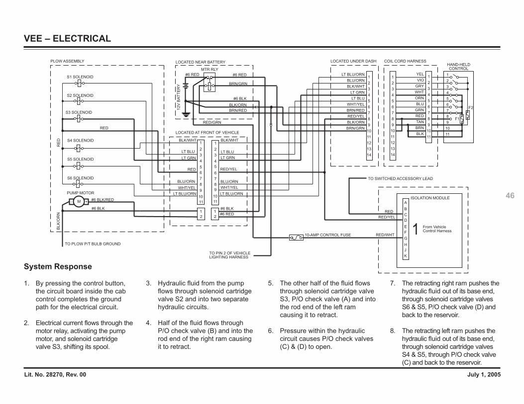
Lit. No. 28270, Rev. 00 July 1, 2005
46
VEE – ELECTRICAL
RED/WHT
RED/YEL
RED/YEL
RED/GRN
BL
K/O
RN
RED/YEL
RED
A
C
B
E
G
F
H
J
K
D
TO SWITCHED ACCESSORY LEAD1
2V
BA
TT
ER
Y
#6 BLK
BRN/RED
BRN/GRN
#6 RED
PLOW ASSEMBLY LOCATED NEAR BATTERY
MTR RLY
#6 RED
LOCATED AT FRONT OF VEHICLE
LT BLU
LT GRN
WHT/YEL
LT BLU
LT GRN
WHT/YEL
#6 BLK
#6 RED
From Vehicle Control Harness1
1
3
5
4
7
6
8
9
10
11
2
1
3
5
4
7
6
8
9
10
11
2
1
2
1
2
LT BLU/ORN
BLU/ORN
RED
BLK/WHT
S1 SOLENOID
S2 SOLENOID
PUMP MOTOR
#6 BLK
#6 BLK/RED- +M
S3 SOLENOID
S4 SOLENOID
S5 SOLENOID
S6 SOLENOID
RED
BLK/WHT
BLU/ORN
LT BLU/ORN
HAND-HELDCONTROL
COIL CORD HARNESS
6
7
5
4WHT
BLK
GRN
ORN
2
3
1YEL
BLU
RED
6
4
3
5
2
1
3
4
6
5
7
2
1
7
8
9
10
11
12
13
14
8
9
10
11
8
9
10
11
VIO
GRY
TAN
BRN
LOCATED UNDER DASH
6
4
3
5
2
1
7
8
9
10
11
12
13
14
BLK/ORN
BRN/GRN
LT BLU/ORN
BLU/ORN
BLK/WHT
LT GRN
LT BLU
WHT/YEL
BRN/RED
10-AMP CONTROL FUSE
BLK/ORN
TO PIN 2 OF VEHICLE LIGHTING HARNESS
ISOLATION MODULE
RE
D
TO PLOW P/T BULB GROUND
F1
F2
System Response
1. By pressing the control button,the circuit board inside the cabcontrol completes the groundpath for the electrical circuit.
2. Electrical current flows through themotor relay, activating the pumpmotor, and solenoid cartridgevalve S3, shifting its spool.
3. Hydraulic fluid from the pumpflows through solenoid cartridgevalve S2 and into two separatehydraulic circuits.
4. Half of the fluid flows throughP/O check valve (B) and into therod end of the right ram causingit to retract.
5. The other half of the fluid flowsthrough solenoid cartridge valveS3, P/O check valve (A) and intothe rod end of the left ramcausing it to retract.
6. Pressure within the hydrauliccircuit causes P/O check valves(C) & (D) to open.
7. The retracting right ram pushes thehydraulic fluid out of its base end,through solenoid cartridge valvesS6 & S5, P/O check valve (D) andback to the reservoir.
8. The retracting left ram pushes thehydraulic fluid out of its base end,through solenoid cartridge valvesS4 & S5, through P/O check valve(C) and back to the reservoir.
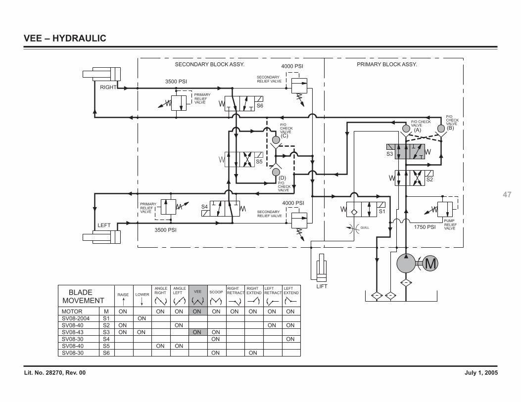
Lit. No. 28270, Rev. 00 July 1, 2005
47
VEE – HYDRAULIC
QUILLLEFT
RIGHT
3500 PSI
3500 PSI
4000 PSI
4000 PSI
1750 PSI
S6
S1
S5
S4
S2
(C)
(D)
(A) (B)
LIFT
M
S3
RELIEF VALVESECONDARY
RELIEF VALVESECONDARY
SECONDARY BLOCK ASSY. PRIMARY BLOCK ASSY.
VALVERELIEFPRIMARY
PRIMARYRELIEFVALVE
VALVERELIEFPUMP
P/O CHECKVALVE
P/O CHECKVALVEP/O
CHECKVALVE
P/O CHECKVALVE
SV08-43 S3 ON ONON ON
SV08-2004 S1 ON
MOVEMENTBLADE RAISE LOWER
SCOOPVEE
SV08-30 S6 ON ON
RIGHT
EXTEND
RIGHT
RETRACT
LEFT
RETRACT EXTEND
LEFT
S4SV08-30 ON ON
SV08-40 S2 ON ON ONON
SV08-40 S5 ON ON
MOTOR M ONONON ON ON ON ONON ON
ANGLE
RIGHT
ANGLE
LEFT
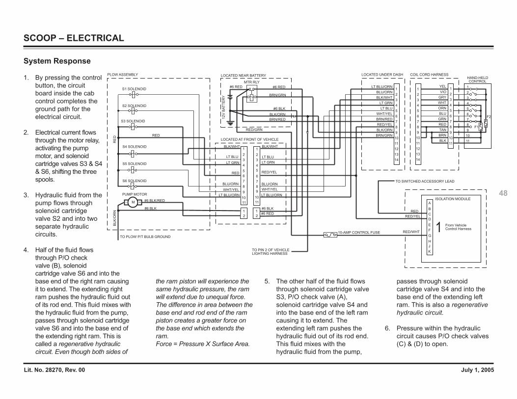
Lit. No. 28270, Rev. 00 July 1, 2005
48
SCOOP – ELECTRICAL
RED
A
C
B
E
G
F
H
J
K
D
TO SWITCHED ACCESSORY LEAD
12V
BA
TT
ER
Y
#6 BLK
BRN/RED
BRN/GRN
#6 RED
PLOW ASSEMBLY LOCATED NEAR BATTERY
MTR RLY
#6 RED
LOCATED AT FRONT OF VEHICLE
LT BLU
LT GRN
WHT/YEL
LT BLU
LT GRN
WHT/YEL
#6 BLK
#6 RED
From Vehicle Control Harness1
1
3
5
4
7
6
8
9
10
11
2
1
3
5
4
7
6
8
9
10
11
2
1
2
1
2
LT BLU/ORN
BLU/ORN
RED
BLK/WHT
S1 SOLENOID
S2 SOLENOID
PUMP MOTOR
#6 BLK
#6 BLK/RED- +M
S3 SOLENOID
S4 SOLENOID
S5 SOLENOID
S6 SOLENOID
RED
BLK/WHT
BLU/ORN
LT BLU/ORN
HAND-HELDCONTROL
COIL CORD HARNESS
6
7
5
4WHT
BLK
GRN
ORN
2
3
1YEL
BLU
RED
6
4
3
5
2
1
3
4
6
5
7
2
1
7
8
9
10
11
12
13
14
8
9
10
11
8
9
10
11
VIO
GRY
TAN
BRN
LOCATED UNDER DASH
6
4
3
5
2
1
7
8
9
10
11
12
13
14
BLK/ORN
BRN/GRN
LT BLU/ORN
BLU/ORN
BLK/WHT
LT GRN
LT BLU
WHT/YEL
BRN/RED
10-AMP CONTROL FUSE
BLK/ORN
TO PIN 2 OF VEHICLE LIGHTING HARNESS
ISOLATION MODULE
RE
D
RED/WHT
RED/YEL
RED/YEL
RED/GRN
BLK
/OR
N
RED/YEL
TO PLOW P/T BULB GROUND
F1
F2
System Response
1. By pressing the controlbutton, the circuitboard inside the cabcontrol completes theground path for theelectrical circuit.
2. Electrical current flowsthrough the motor relay,activating the pumpmotor, and solenoidcartridge valves S3 & S4& S6, shifting the threespools.
3. Hydraulic fluid from thepump flows throughsolenoid cartridgevalve S2 and into twoseparate hydrauliccircuits.
4. Half of the fluid flowsthrough P/O checkvalve (B), solenoidcartridge valve S6 and into thebase end of the right ram causingit to extend. The extending rightram pushes the hydraulic fluid outof its rod end. This fluid mixes withthe hydraulic fluid from the pump,passes through solenoid cartridgevalve S6 and into the base end ofthe extending right ram. This iscalled a regenerative hydrauliccircuit. Even though both sides of
the ram piston will experience thesame hydraulic pressure, the ramwill extend due to unequal force.The difference in area between thebase end and rod end of the rampiston creates a greater force onthe base end which extends theram.Force = Pressure X Surface Area.
5. The other half of the fluid flowsthrough solenoid cartridge valveS3, P/O check valve (A),solenoid cartridge valve S4 andinto the base end of the left ramcausing it to extend. Theextending left ram pushes thehydraulic fluid out of its rod end.This fluid mixes with thehydraulic fluid from the pump,
passes through solenoidcartridge valve S4 and into thebase end of the extending leftram. This is also a regenerativehydraulic circuit.
6. Pressure within the hydrauliccircuit causes P/O check valves(C) & (D) to open.

Lit. No. 28270, Rev. 00 July 1, 2005
49
SCOOP – HYDRAULIC
QUILLLEFT
RIGHT
3500 PSI
3500 PSI
4000 PSI
4000 PSI
1750 PSI
S1
S2
(C)
(D)
(A) (B)
LIFT
M
S6
S3
S4
RELIEF VALVESECONDARY
RELIEF VALVESECONDARY
SECONDARY BLOCK ASSY. PRIMARY BLOCK ASSY.
VALVERELIEFPRIMARY
PRIMARY
RELIEFVALVE
VALVERELIEFPUMP
P/O CHECKVALVE
P/O CHECKVALVEP/O
CHECKVALVE
P/O CHECKVALVE
S5
SV08-43 S3 ON ONON ON
SV08-2004 S1 ON
MOVEMENTBLADE RAISE LOWER
SCOOPVEE
SV08-30 S6 ON ON
RIGHT
EXTEND
RIGHT
RETRACT
LEFT
RETRACT EXTEND
LEFT
S4SV08-30 ON ON
SV08-40 S2 ON ON ONON
SV08-40 S5 ON ON
MOTOR M ONONON ON ON ON ONON ON
ANGLE
RIGHT
ANGLE
LEFT
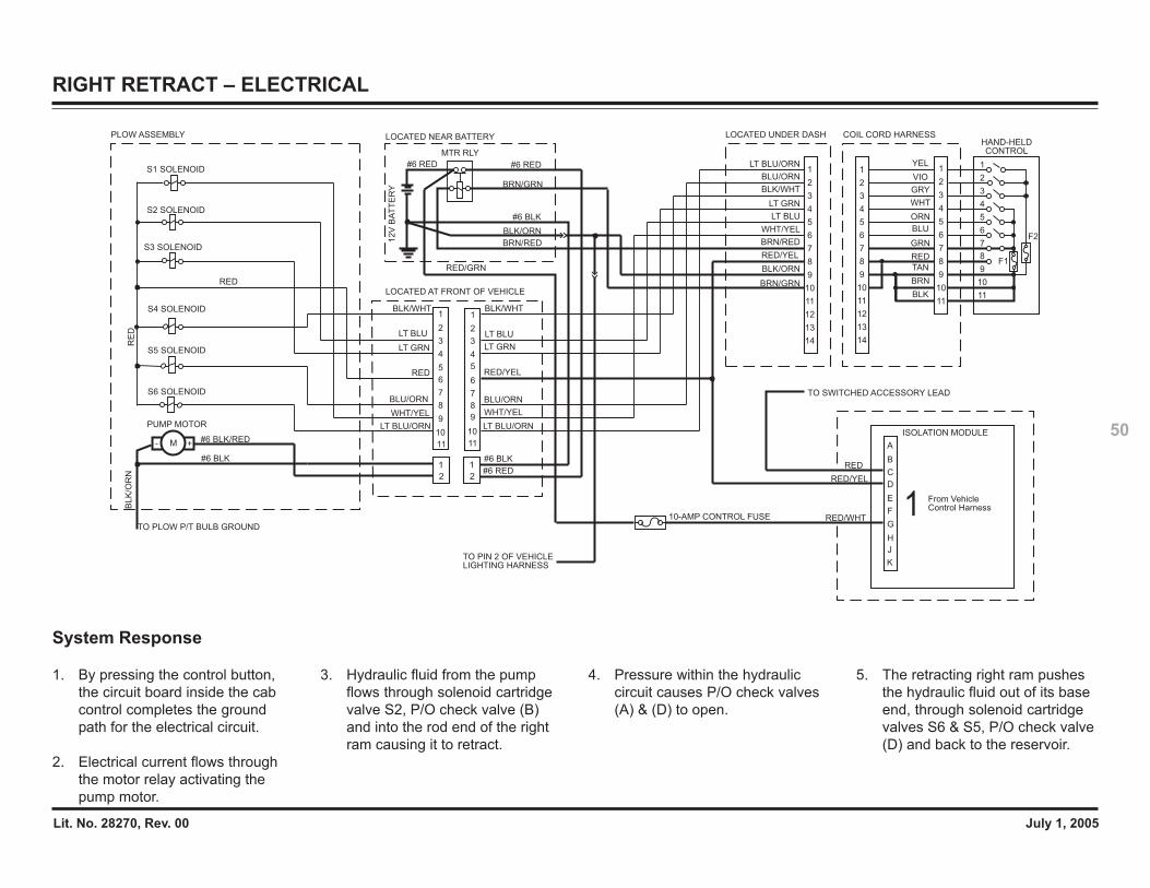
Lit. No. 28270, Rev. 00 July 1, 2005
50
RIGHT RETRACT – ELECTRICAL
RED
A
C
B
E
G
F
H
J
K
D
TO SWITCHED ACCESSORY LEAD1
2V
BA
TT
ER
Y
#6 BLK
BRN/RED
BRN/GRN
#6 RED
PLOW ASSEMBLY LOCATED NEAR BATTERY
MTR RLY
#6 RED
LOCATED AT FRONT OF VEHICLE
LT BLU
LT GRN
WHT/YEL
LT BLU
LT GRN
WHT/YEL
#6 BLK
#6 RED
From Vehicle Control Harness1
1
3
5
4
7
6
8
9
10
11
2
1
3
5
4
7
6
8
9
10
11
2
1
2
1
2
LT BLU/ORN
BLU/ORN
RED
BLK/WHT
S1 SOLENOID
S2 SOLENOID
RE
D
PUMP MOTOR
#6 BLK
#6 BLK/RED- +M
S3 SOLENOID
S4 SOLENOID
S5 SOLENOID
S6 SOLENOID
RED
BLK/WHT
BLU/ORN
LT BLU/ORN
HAND-HELDCONTROL
COIL CORD HARNESS
6
7
5
4WHT
BLK
GRN
ORN
2
3
1YEL
BLU
RED
6
4
3
5
2
1
3
4
6
5
7
2
1
7
8
9
10
11
12
13
14
8
9
10
11
8
9
10
11
VIO
GRY
TAN
BRN
LOCATED UNDER DASH
6
4
3
5
2
1
7
8
9
10
11
12
13
14
BLK/ORN
BRN/GRN
LT BLU/ORN
BLU/ORN
BLK/WHT
LT GRN
LT BLU
WHT/YEL
BRN/RED
10-AMP CONTROL FUSE
BLK/ORN
TO PIN 2 OF VEHICLE LIGHTING HARNESS
ISOLATION MODULE
RED/WHT
RED/YEL
RED/YEL
RED/GRN
TO PLOW P/T BULB GROUND
BL
K/O
RN
RED/YEL
F1
F2
System Response
1. By pressing the control button,the circuit board inside the cabcontrol completes the groundpath for the electrical circuit.
2. Electrical current flows throughthe motor relay activating thepump motor.
3. Hydraulic fluid from the pumpflows through solenoid cartridgevalve S2, P/O check valve (B)and into the rod end of the rightram causing it to retract.
4. Pressure within the hydrauliccircuit causes P/O check valves(A) & (D) to open.
5. The retracting right ram pushesthe hydraulic fluid out of its baseend, through solenoid cartridgevalves S6 & S5, P/O check valve(D) and back to the reservoir.
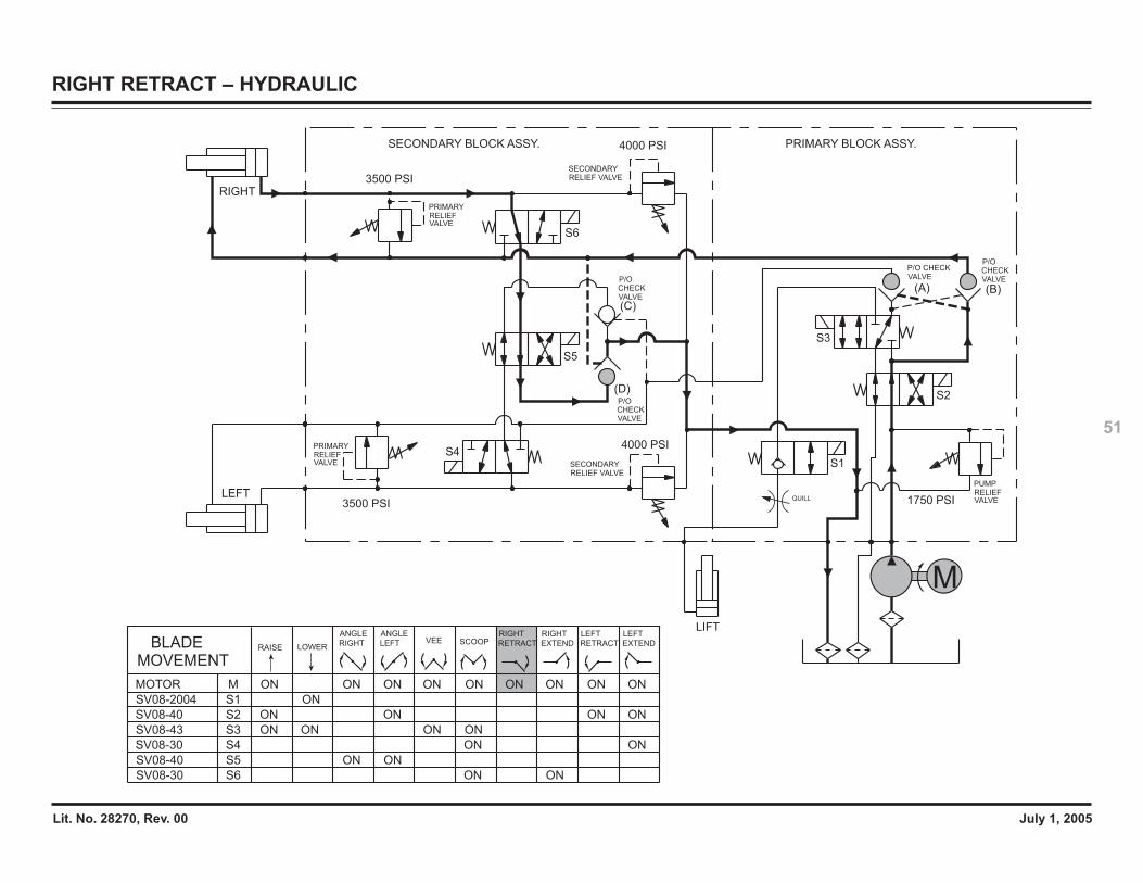
Lit. No. 28270, Rev. 00 July 1, 2005
51
RIGHT RETRACT – HYDRAULIC
QUILLLEFT
RIGHT
3500 PSI
3500 PSI
4000 PSI
4000 PSI
1750 PSI
S6
S3
S1
S5
S4
S2
(C)
(D)
(A) (B)
LIFT
M
RELIEF VALVESECONDARY
RELIEF VALVESECONDARY
SECONDARY BLOCK ASSY. PRIMARY BLOCK ASSY.
VALVERELIEFPRIMARY
PRIMARYRELIEFVALVE
VALVERELIEFPUMP
VALVECHECKP/O
VALVEP/O CHECK
VALVECHECKP/O VALVE
CHECKP/O
SV08-43 S3 ON ONON ON
SV08-2004 S1 ON
MOVEMENTBLADE RAISE LOWER
SCOOPVEE
SV08-30 S6 ON ON
RIGHT
EXTEND
RIGHT
RETRACT
LEFT
RETRACT EXTEND
LEFT
S4SV08-30 ON ON
SV08-40 S2 ON ON ONON
SV08-40 S5 ON ON
MOTOR M ONONON ON ON ON ONON ON
ANGLE
RIGHT
ANGLE
LEFT
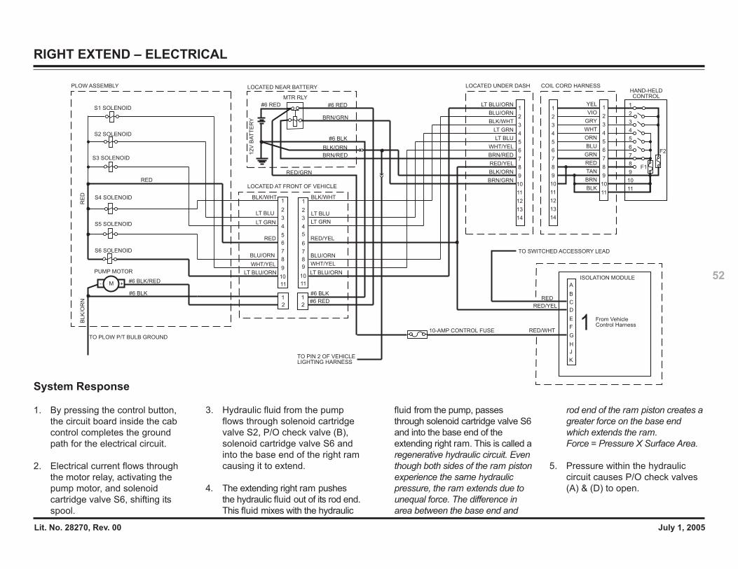
Lit. No. 28270, Rev. 00 July 1, 2005
52
RIGHT EXTEND – ELECTRICAL
RED
A
C
B
E
G
F
H
J
K
D
TO SWITCHED ACCESSORY LEAD1
2V
BA
TT
ER
Y
#6 BLK
BRN/RED
BRN/GRN
#6 RED
PLOW ASSEMBLY LOCATED NEAR BATTERY
MTR RLY
#6 RED
LOCATED AT FRONT OF VEHICLE
LT BLU
LT GRN
WHT/YEL
LT BLU
LT GRN
WHT/YEL
#6 BLK
#6 RED
From Vehicle Control Harness1
1
3
5
4
7
6
8
9
10
11
2
1
3
5
4
7
6
8
9
10
11
2
1
2
1
2
LT BLU/ORN
BLU/ORN
RED
BLK/WHT
S1 SOLENOID
S2 SOLENOID
PUMP MOTOR
#6 BLK
#6 BLK/RED- +M
S3 SOLENOID
S4 SOLENOID
S5 SOLENOID
S6 SOLENOID
RED
BLK/WHT
BLU/ORN
LT BLU/ORN
HAND-HELDCONTROL
COIL CORD HARNESS
6
7
5
4WHT
BLK
GRN
ORN
2
3
1YEL
BLU
RED
6
4
3
5
2
1
3
4
6
5
7
2
1
7
8
9
10
11
12
13
14
8
9
10
11
8
9
10
11
VIO
GRY
TAN
BRN
LOCATED UNDER DASH
6
4
3
5
2
1
7
8
9
10
11
12
13
14
BLK/ORN
BRN/GRN
LT BLU/ORN
BLU/ORN
BLK/WHT
LT GRN
LT BLU
WHT/YEL
BRN/RED
10-AMP CONTROL FUSE
BLK/ORN
TO PIN 2 OF VEHICLE LIGHTING HARNESS
ISOLATION MODULE
RED/WHT
RED/YEL
RED/YEL
RED/GRN
BL
K/O
RN
RED/YEL
TO PLOW P/T BULB GROUND
RE
D
F1
F2
System Response
1. By pressing the control button,the circuit board inside the cabcontrol completes the groundpath for the electrical circuit.
2. Electrical current flows throughthe motor relay, activating thepump motor, and solenoidcartridge valve S6, shifting itsspool.
3. Hydraulic fluid from the pumpflows through solenoid cartridgevalve S2, P/O check valve (B),solenoid cartridge valve S6 andinto the base end of the right ramcausing it to extend.
4. The extending right ram pushesthe hydraulic fluid out of its rod end.This fluid mixes with the hydraulic
fluid from the pump, passesthrough solenoid cartridge valve S6and into the base end of theextending right ram. This is called aregenerative hydraulic circuit. Eventhough both sides of the ram pistonexperience the same hydraulicpressure, the ram extends due tounequal force. The difference inarea between the base end and
rod end of the ram piston creates agreater force on the base endwhich extends the ram.Force = Pressure X Surface Area.
5. Pressure within the hydrauliccircuit causes P/O check valves(A) & (D) to open.
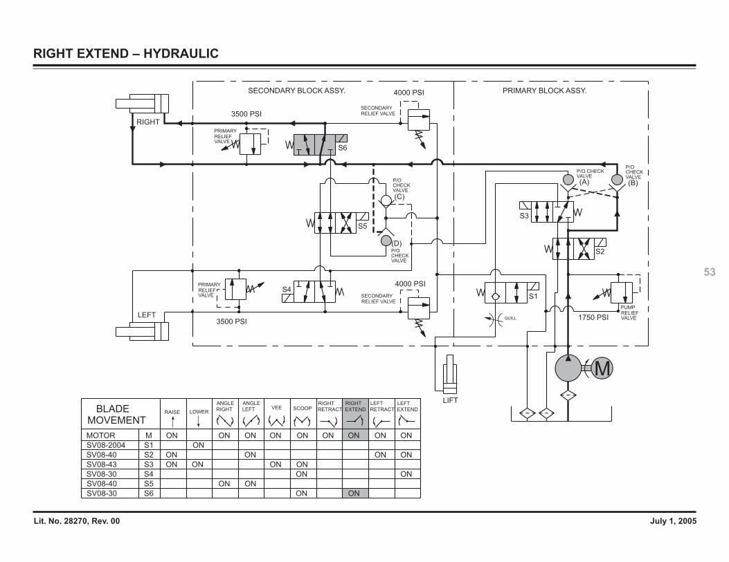
Lit. No. 28270, Rev. 00 July 1, 2005
53
RIGHT EXTEND – HYDRAULIC
QUILLLEFT
RIGHT
3500 PSI
3500 PSI
4000 PSI
4000 PSI
1750 PSI
S3
S1
S5
S4
S2
(C)
(D)
(A) (B)
LIFT
M
S6
RELIEF VALVESECONDARY
RELIEF VALVESECONDARY
SECONDARY BLOCK ASSY. PRIMARY BLOCK ASSY.
VALVERELIEFPRIMARY
PRIMARYRELIEFVALVE
VALVERELIEFPUMP
P/O CHECKVALVE
P/O CHECKVALVE
P/O CHECKVALVE
P/O CHECKVALVE
SV08-43 S3 ON ONON ON
SV08-2004 S1 ON
MOVEMENTBLADE RAISE LOWER
SCOOPVEE
SV08-30 S6 ON ON
RIGHT
EXTEND
RIGHT
RETRACT
LEFT
RETRACT EXTEND
LEFT
S4SV08-30 ON ON
SV08-40 S2 ON ON ONON
SV08-40 S5 ON ON
MOTOR M ONONON ON ON ON ONON ON
ANGLE
RIGHT
ANGLE
LEFT
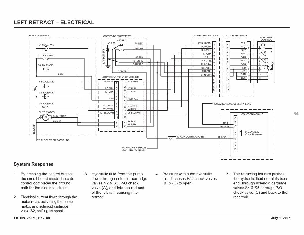
Lit. No. 28270, Rev. 00 July 1, 2005
54
LEFT RETRACT – ELECTRICAL
RED
A
C
B
E
G
F
H
J
K
D
TO SWITCHED ACCESSORY LEAD1
2V
BA
TT
ER
Y
#6 BLK
BRN/RED
BRN/GRN
#6 RED
PLOW ASSEMBLY LOCATED NEAR BATTERY
MTR RLY
#6 RED
LOCATED AT FRONT OF VEHICLE
LT BLU
LT GRN
WHT/YEL
LT BLU
LT GRN
WHT/YEL
#6 BLK
#6 RED
From Vehicle Control Harness1
1
3
5
4
7
6
8
9
10
11
2
1
3
5
4
7
6
8
9
10
11
2
1
2
1
2
LT BLU/ORN
BLU/ORN
RED
BLK/WHT
S1 SOLENOID
S2 SOLENOID
RE
D
PUMP MOTOR
#6 BLK
#6 BLK/RED- +M
S3 SOLENOID
S4 SOLENOID
S5 SOLENOID
S6 SOLENOID
RED
BLK/WHT
BLU/ORN
LT BLU/ORN
HAND-HELDCONTROL
COIL CORD HARNESS
6
7
5
4WHT
BLK
GRN
ORN
2
3
1YEL
BLU
RED
6
4
3
5
2
1
3
4
6
5
7
2
1
7
8
9
10
11
12
13
14
8
9
10
11
8
9
10
11
VIO
GRY
TAN
BRN
LOCATED UNDER DASH
6
4
3
5
2
1
7
8
9
10
11
12
13
14
BLK/ORN
BRN/GRN
LT BLU/ORN
BLU/ORN
BLK/WHT
LT GRN
LT BLU
WHT/YEL
BRN/RED
10-AMP CONTROL FUSE
BLK/ORN
TO PIN 2 OF VEHICLE LIGHTING HARNESS
ISOLATION MODULE
RED/WHT
RED/YEL
RED/YEL
RED/GRN
BLK
/OR
N
RED/YEL
TO PLOW P/T BULB GROUND
F1
F2
System Response
1. By pressing the control button,the circuit board inside the cabcontrol completes the groundpath for the electrical circuit.
2. Electrical current flows through themotor relay, activating the pumpmotor, and solenoid cartridgevalve S2, shifting its spool.
3. Hydraulic fluid from the pumpflows through solenoid cartridgevalves S2 & S3, P/O checkvalve (A), and into the rod endof the left ram causing it toretract.
4. Pressure within the hydrauliccircuit causes P/O check valves(B) & (C) to open.
5. The retracting left ram pushesthe hydraulic fluid out of its baseend, through solenoid cartridgevalves S4 & S5, through P/Ocheck valve (C) and back to thereservoir.
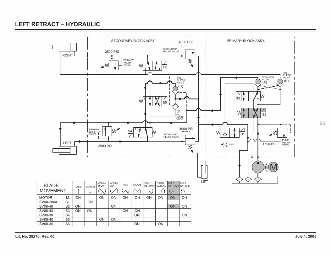
Lit. No. 28270, Rev. 00 July 1, 2005
55
LEFT RETRACT – HYDRAULIC
QUILL
S6
S3
S1
LEFT
RIGHT
3500 PSI
3500 PSI
4000 PSI
4000 PSI
1750 PSI
S5
S4
(C)
(D)
(A) (B)
LIFT
M
S2
RELIEF VALVESECONDARY
RELIEF VALVESECONDARY
SECONDARY BLOCK ASSY. PRIMARY BLOCK ASSY.
VALVERELIEFPRIMARY
PRIMARYRELIEFVALVE
VALVERELIEFPUMP
P/O CHECKVALVE
P/O CHECKVALVE
P/O CHECKVALVE
P/O CHECKVALVE
SV08-43 S3 ON ONON ON
SV08-2004 S1 ON
MOVEMENTBLADE RAISE LOWER
SCOOPVEE
SV08-30 S6 ON ON
RIGHT
EXTEND
RIGHT
RETRACT
LEFT
RETRACT EXTEND
LEFT
S4SV08-30 ON ON
SV08-40 S2 ON ON ONON
SV08-40 S5 ON ON
MOTOR M ONONON ON ON ON ONON ON
ANGLE
RIGHT
ANGLE
LEFT
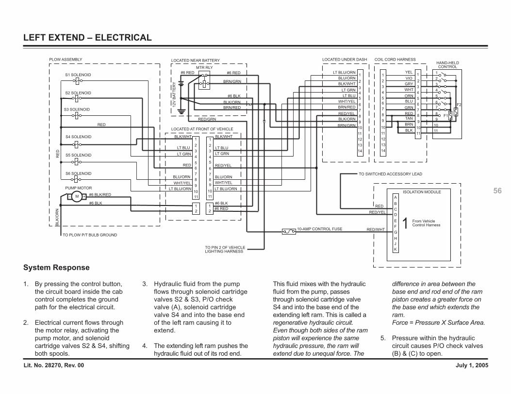
Lit. No. 28270, Rev. 00 July 1, 2005
56
LEFT EXTEND – ELECTRICAL
RED
A
C
B
E
G
F
H
J
K
D
TO SWITCHED ACCESSORY LEAD1
2V
BA
TT
ER
Y
#6 BLK
BRN/RED
BRN/GRN
#6 RED
PLOW ASSEMBLY LOCATED NEAR BATTERY
MTR RLY
#6 RED
LOCATED AT FRONT OF VEHICLE
LT BLU
LT GRN
WHT/YEL
LT BLU
LT GRN
WHT/YEL
#6 BLK
#6 RED
From Vehicle Control Harness1
1
3
5
4
7
6
8
9
10
11
2
1
3
5
4
7
6
8
9
10
11
2
1
2
1
2
LT BLU/ORN
BLU/ORN
RED
BLK/WHT
S1 SOLENOID
S2 SOLENOID
PUMP MOTOR
#6 BLK
#6 BLK/RED- +M
S3 SOLENOID
S4 SOLENOID
S5 SOLENOID
S6 SOLENOID
RED
BLK/WHT
BLU/ORN
LT BLU/ORN
HAND-HELDCONTROL
COIL CORD HARNESS
6
7
5
4WHT
BLK
GRN
ORN
2
3
1YEL
BLU
RED
6
4
3
5
2
1
3
4
6
5
7
2
1
7
8
9
10
11
12
13
14
8
9
10
11
8F1
F2
9
10
11
VIO
GRY
TAN
BRN
LOCATED UNDER DASH
6
4
3
5
2
1
7
8
9
10
11
12
13
14
BLK/ORN
BRN/GRN
LT BLU/ORN
BLU/ORN
BLK/WHT
LT GRN
LT BLU
WHT/YEL
BRN/RED
10-AMP CONTROL FUSE
BLK/ORN
TO PIN 2 OF VEHICLE LIGHTING HARNESS
ISOLATION MODULE
RE
D
RED/WHT
RED/YEL
RED/YEL
RED/GRN
TO PLOW P/T BULB GROUND
RED/YEL
BLK
/OR
N
System Response
1. By pressing the control button,the circuit board inside the cabcontrol completes the groundpath for the electrical circuit.
2. Electrical current flows throughthe motor relay, activating thepump motor, and solenoidcartridge valves S2 & S4, shiftingboth spools.
3. Hydraulic fluid from the pumpflows through solenoid cartridgevalves S2 & S3, P/O checkvalve (A), solenoid cartridgevalve S4 and into the base endof the left ram causing it toextend.
4. The extending left ram pushes thehydraulic fluid out of its rod end.
This fluid mixes with the hydraulicfluid from the pump, passesthrough solenoid cartridge valveS4 and into the base end of theextending left ram. This is called aregenerative hydraulic circuit.Even though both sides of the rampiston will experience the samehydraulic pressure, the ram willextend due to unequal force. The
difference in area between thebase end and rod end of the rampiston creates a greater force onthe base end which extends theram.Force = Pressure X Surface Area.
5. Pressure within the hydrauliccircuit causes P/O check valves(B) & (C) to open.
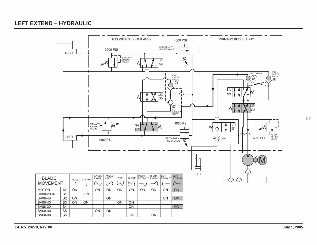
Lit. No. 28270, Rev. 00 July 1, 2005
57
LEFT EXTEND – HYDRAULIC
LEFT
RIGHT
3500 PSI
3500 PSI
4000 PSI
4000 PSI
1750 PSI
S6
S3
S1
S5
(C)
(D)
(A) (B)
LIFT
M
S4
S2
RELIEF VALVESECONDARY
RELIEF VALVESECONDARY
P/OCHECKVALVE
VALVEP/O CHECK
SECONDARY BLOCK ASSY. PRIMARY BLOCK ASSY.
VALVERELIEFPRIMARY
PRIMARYRELIEFVALVE
VALVERELIEFPUMP
P/OCHECKVALVE
P/OCHECKVALVE
QUILL
SV08-43 S3 ON ONON ON
SV08-2004 S1 ON
MOVEMENTBLADE RAISE LOWER
SCOOPVEE
SV08-30 S6 ON ON
RIGHT
EXTEND
RIGHT
RETRACT
LEFT
RETRACT EXTEND
LEFT
S4SV08-30 ON ON
SV08-40 S2 ON ON ONON
SV08-40 S5 ON ON
MOTOR M ONONON ON ON ON ONON ON
ANGLE
RIGHT
ANGLE
LEFT
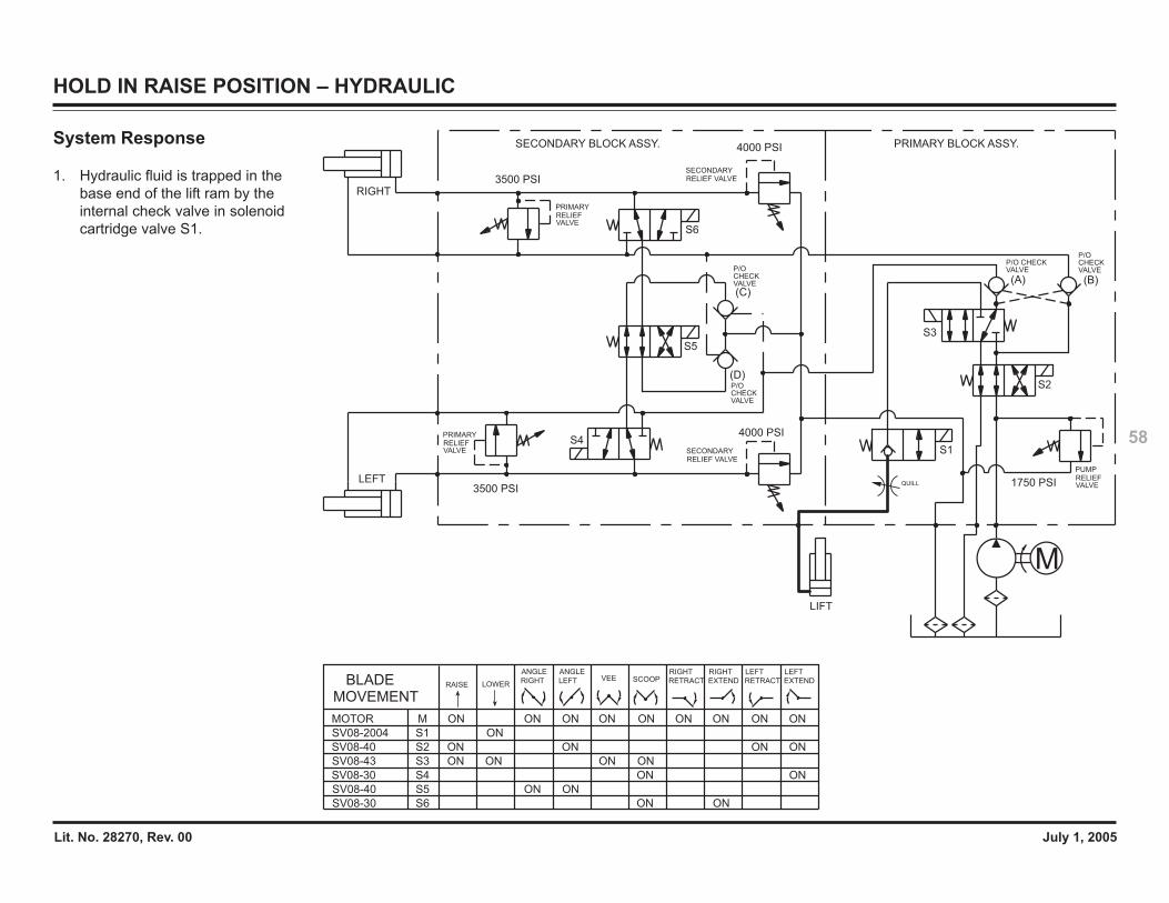
Lit. No. 28270, Rev. 00 July 1, 2005
58
HOLD IN RAISE POSITION – HYDRAULIC
QUILL
M
LEFT
RIGHT
3500 PSI
3500 PSI
4000 PSI
4000 PSI
1750 PSI
S6
S3
S1
S5
S4
S2
(C)
(D)
(A) (B)
LIFT
RELIEF VALVESECONDARY
RELIEF VALVESECONDARY
SECONDARY BLOCK ASSY. PRIMARY BLOCK ASSY.
VALVERELIEFPRIMARY
PRIMARYRELIEFVALVE
VALVERELIEFPUMP
P/O CHECKVALVE
P/O CHECKVALVEP/O
CHECKVALVE
P/O CHECKVALVE
SV08-43 S3 ON ONON ON
SV08-2004 S1 ON
MOVEMENTBLADE RAISE LOWER
SCOOPVEE
SV08-30 S6 ON ON
RIGHT
EXTEND
RIGHT
RETRACT
LEFT
RETRACT EXTEND
LEFT
S4SV08-30 ON ON
SV08-40 S2 ON ON ONON
SV08-40 S5 ON ON
MOTOR M ONONON ON ON ON ONON ON
ANGLE
RIGHT
ANGLE
LEFT
System Response
1. Hydraulic fluid is trapped in thebase end of the lift ram by theinternal check valve in solenoidcartridge valve S1.
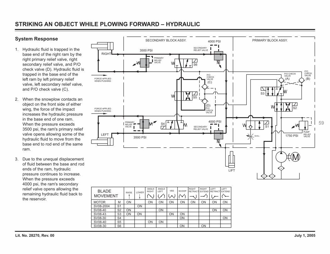
Lit. No. 28270, Rev. 00 July 1, 2005
59
STRIKING AN OBJECT WHILE PLOWING FORWARD – HYDRAULIC
QUILL
M
LEFT
RIGHT
3500 PSI
3500 PSI
4000 PSI
4000 PSI
1750 PSI
S6
S3
S1
S5
S4
S2
(C)
(D)
(A) (B)
LIFT
FORCE APPLIEDWHEN PUSHING
FORCE APPLIEDWHEN PUSHING
RELIEF VALVESECONDARY
RELIEF VALVESECONDARY
P/O CHECKVALVE
P/O CHECKVALVE
SECONDARY BLOCK ASSY. PRIMARY BLOCK ASSY.
VALVERELIEFPRIMARY
PRIMARYRELIEFVALVE
VALVERELIEFPUMP
P/O CHECKVALVE
P/O CHECKVALVE
SV08-43 S3 ON ONON ON
SV08-2004 S1 ON
MOVEMENTBLADE RAISE LOWER
SCOOPVEE
SV08-30 S6 ON ON
RIGHT
EXTEND
RIGHT
RETRACT
LEFT
RETRACT EXTEND
LEFT
S4SV08-30 ON ON
SV08-40 S2 ON ON ONON
SV08-40 S5 ON ON
MOTOR M ONONON ON ON ON ONON ON
ANGLE
RIGHT
ANGLE
LEFT
System Response
1. Hydraulic fluid is trapped in thebase end of the right ram by theright primary relief valve, rightsecondary relief valve, and P/Ocheck valve (D). Hydraulic fluid istrapped in the base end of theleft ram by left primary reliefvalve, left secondary relief valve,and P/O check valve (C).
2. When the snowplow contacts anobject on the front side of eitherwing, the force of the impactincreases the hydraulic pressurein the base end of one ram.When the pressure exceeds3500 psi, the ram's primary reliefvalve opens allowing some of thehydraulic fluid to move from thebase end to rod end of the sameram.
3. Due to the unequal displacementof fluid between the base and rodends of the ram, hydraulicpressure continues to increase.When the pressure exceeds4000 psi, the ram's secondaryrelief valve opens allowing theremaining hydraulic fluid back tothe reservoir.
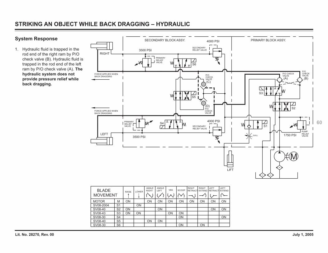
Lit. No. 28270, Rev. 00 July 1, 2005
60
STRIKING AN OBJECT WHILE BACK DRAGGING – HYDRAULIC
QUILL
M
LEFT
RIGHT
3500 PSI
3500 PSI
4000 PSI
4000 PSI
1750 PSI
S6
S3
S1
S5
S4
S2
(C)
(D)
(A) (B)
LIFT
FORCE APPLIED WHENBACK DRAGGING
FORCE APPLIED WHENBACK DRAGGING
RELIEF VALVESECONDARY
RELIEF VALVESECONDARY
SECONDARY BLOCK ASSY. PRIMARY BLOCK ASSY.
VALVERELIEFPRIMARY
PRIMARYRELIEFVALVE
VALVERELIEFPUMP
P/O CHECKVALVE
P/O CHECKVALVEP/O
CHECKVALVE
P/O CHECKVALVE
SV08-43 S3 ON ONON ON
SV08-2004 S1 ON
MOVEMENTBLADE RAISE LOWER
SCOOPVEE
SV08-30 S6 ON ON
RIGHT
EXTEND
RIGHT
RETRACT
LEFT
RETRACT EXTEND
LEFT
S4SV08-30 ON ON
SV08-40 S2 ON ON ONON
SV08-40 S5 ON ON
MOTOR M ONONON ON ON ON ONON ON
ANGLE
RIGHT
ANGLE
LEFT
System Response
1. Hydraulic fluid is trapped in therod end of the right ram by P/Ocheck valve (B). Hydraulic fluid istrapped in the rod end of the leftram by P/O check valve (A). Thehydraulic system does notprovide pressure relief whileback dragging.
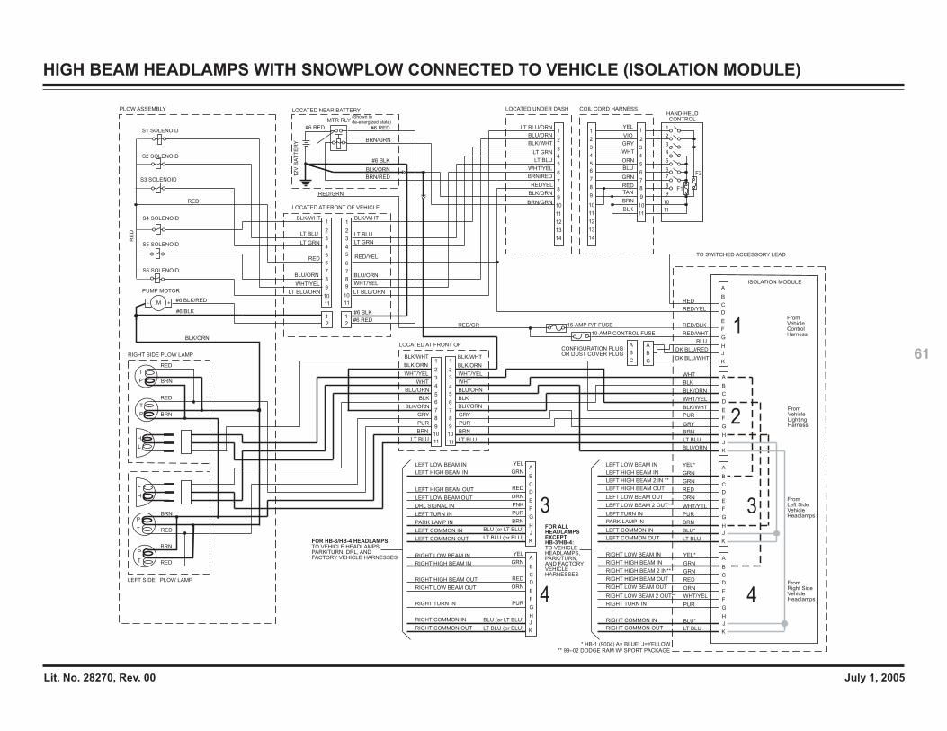
Lit. No. 28270, Rev. 00 July 1, 2005
61
HIGH BEAM HEADLAMPS WITH SNOWPLOW CONNECTED TO VEHICLE (ISOLATION MODULE)
From Vehicle Control Harness
From Vehicle Lighting Harness
From Left Side Vehicle Headlamps
From Right Side Vehicle Headlamps
BLU/ORN
LT BLU
BRN
GRY
PUR
BLK/WHT
WHT/YEL
BLK/ORN
BLK
WHT
DK BLU/WHT
DK BLU/RED
BLU
RED/WHT
RED/BLK
RED/YEL
RED
YEL*
LT BLU
BLU*
PUR
WHT/YEL
ORN
RED
GRN
GRN
YEL*
LT BLU
BLU*
BRN
PUR
WHT/YEL
ORN
RED
GRN
GRN
TO SWITCHED ACCESSORY LEAD
12V
BA
TT
ER
Y
#6 BLK
BRN/RED
BRN/GRN
#6 RED
CONFIGURATION PLUG OR DUST COVER PLUG
PLOW ASSEMBLY LOCATED NEAR BATTERY
MTR RLY
#6 RED
LOCATED AT FRONT OF VEHICLE
LT BLU
LT GRN
WHT/YEL
LT BLU
LT GRN
WHT/YEL
#6 BLK
#6 RED
4
3
2
1
RIGHT COMMON OUT
RIGHT COMMON IN
RIGHT TURN IN
RIGHT LOW BEAM OUT
RIGHT HIGH BEAM OUT
RIGHT HIGH BEAM IN
RIGHT LOW BEAM IN
LEFT COMMON OUT
LEFT COMMON IN
PARK LAMP IN
LEFT TURN IN
DRL SIGNAL IN
LEFT LOW BEAM OUT
LEFT HIGH BEAM OUT
LEFT HIGH BEAM IN
LEFT LOW BEAM IN YEL
LT BLU (or BLU)
BLU (or LT BLU)
PUR
ORN
RED
GRN
YEL
LT BLU (or BLU)
BLU (or LT BLU)
BRN
PUR
PNK
ORN
RED
GRNA
C
B
E
G
F
H
D
A
C
B
E
G
F
H
D
J
K
J
KRIGHT COMMON OUT
RIGHT COMMON IN
RIGHT TURN IN
RIGHT LOW BEAM 2 OUT**
RIGHT LOW BEAM OUT
RIGHT HIGH BEAM OUT
RIGHT HIGH BEAM 2 IN**
RIGHT HIGH BEAM IN
RIGHT LOW BEAM IN
LEFT COMMON OUT
LEFT COMMON IN
PARK LAMP IN
LEFT TURN IN
LEFT LOW BEAM 2 OUT**
LEFT LOW BEAM OUT
LEFT HIGH BEAM OUT
LEFT HIGH BEAM 2 IN **
LEFT HIGH BEAM IN
LEFT LOW BEAM IN
1
3
5
4
7
6
8
9
10
11
2
1
3
5
4
7
6
8
9
10
11
2
1
2
1
2
RIGHT SIDE PLOW LAMP
P
T
RED
BRN
RED
BRNP
T
L
H
LEFT SIDE PLOW LAMP
BRN
BRN
RED
RED
P
T
P
T
L
H
LT BLU/ORN
BLU/ORN
RED
BLK/WHT
LOCATED AT FRONT OF
BRN
PUR
GRY
WHT
BLK/ORN
LT BLU
BLK
WHT/YEL
BLK/ORN
BLK/WHT
BLU/ORN
BRN
PUR
GRY
WHT
BLU/ORN
LT BLU
WHT/YEL
BLK/ORN
BLK/WHT
BLK
BLK/ORN
1
3
5
4
7
6
8
9
10
11
2
1
3
2
5
7
6
8
9
10
11
4
S1 SOLENOID
S2 SOLENOID
RE
D
PUMP MOTOR
#6 BLK
#6 BLK/RED- +M
S3 SOLENOID
S4 SOLENOID
S5 SOLENOID
S6 SOLENOID
RED
BLK/WHT
RED/YEL
BLU/ORN
LT BLU/ORN
HAND-HELDCONTROL
COIL CORD HARNESS
6
7
5
4WHT
BLK
GRN
ORN
2
3
1YEL
BLU
RED
6
4
3
5
2
1
3
4
6
5
7
2
1
7
8
9
10
11
12
13
14
8
9
10
11
8
9
10
11
VIO
GRY
TAN
BRN
LOCATED UNDER DASH
6
4
3
5
2
1
7
8
9
10
11
12
13
14
REDYEL
BLK/ORN
BRN/GRN
LT BLU/ORN
BLU/ORN
BLK/WHT
LT GRN
LT BLU
WHT/YEL
BRN/RED
15-AMP P/T FUSE
10-AMP CONTROL FUSE
A
C
B
A
C
B
* HB-1 (9004) A= BLUE, J=YELLOW** 99–02 DODGE RAM W/ SPORT PACKAGE
BLK/ORN
RED/GRN
(Shown in
de-energized state)
ISOLATION MODULE
4
3
A
C
B
E
G
F
H
J
K
D
A
C
B
E
G
F
H
J
K
D
A
C
B
E
G
F
H
J
K
D
A
C
B
E
G
F
H
J
K
D
RED/GR
BLK/ORN
FOR HB-3/HB-4 HEADLAMPS:TO VEHICLE HEADLAMPS,PARK/TURN, DRL, ANDFACTORY VEHICLE HARNESSES
EXCEPT
FOR ALLHEADLAMPS
TO VEHICLE HEADLAMPS,PARK/TURN, AND FACTORYVEHICLEHARNESSES
HB-3/HB-4:
F1
F2

Lit. No. 28270, Rev. 00 July 1, 2005
62
LOW BEAM HEADLAMPS WITH SNOWPLOW CONNECTED TO VEHICLE (ISOLATION MODULE)
BLU/ORN
LT BLU
BRN
GRY
PUR
BLK/WHT
WHT/YEL
BLK/ORN
BLK
WHT
DK BLU WHT
DK BLU/RED
BLU
RED/WHT
RED/YEL
RED/BLK
RED
YEL*
A
C
B
E
G
F
H
J
K
LT BLU
BLU*
PUR
WHT/YEL
ORN
RED
GRN
YEL*
LT BLU
BLU*
BRN
PUR
WHT/YEL
ORN
RED
GRN
A
C
B
E
G
F
H
J
K
D
TO SWITCHED ACCESSORY LEAD
12V
BA
TT
ER
Y
#6 BLK
BRN/RED
BRN/GRN
#6 RED
CONFIGURATION PLUG OR DUST COVER PLUG
PLOW ASSEMBLY LOCATED NEAR BATTERY
MTR RLY
#6 RED
LOCATED AT FRONT OF VEHICLE
LT BLU
LT GRN
WHT/YEL
LT BLU
LT GRN
WHT/YEL
#6 BLK
#6 REDFrom Vehicle Control Harness
From Vehicle Lighting Harness
From Left Side Vehicle Headlamps
From Right Side Vehicle Headlamps4
3
2
1
RIGHT COMMON OUT
RIGHT COMMON IN
RIGHT TURN IN
RIGHT LOW BEAM OUT
RIGHT HIGH BEAM OUT
RIGHT HIGH BEAM IN
RIGHT LOW BEAM IN
LEFT COMMON OUT
LEFT COMMON IN
PARK LAMP IN
LEFT TURN IN
DRL SIGNAL IN
LEFT LOW BEAM OUT
LEFT HIGH BEAM OUT
LEFT HIGH BEAM IN
LEFT LOW BEAM IN YEL
PUR
ORN
RED
GRN
YEL
BRN
PUR
ORN
RED
GRNA
C
B
E
G
F
H
D
A
C
B
E
G
F
H
D
J
K
J
K RIGHT COMMON OUT
RIGHT COMMON IN
RIGHT TURN IN
RIGHT LOW BEAM 2 OUT**
RIGHT LOW BEAM OUT
RIGHT HIGH BEAM OUT
RIGHT HIGH BEAM 2 IN**
RIGHT HIGH BEAM IN
RIGHT LOW BEAM IN
LEFT COMMON OUT
LEFT COMMON IN
PARK LAMP IN
LEFT TURN IN
LEFT LOW BEAM 2 OUT**
LEFT LOW BEAM OUT
LEFT HIGH BEAM OUT
LEFT HIGH BEAM 2 IN **
LEFT HIGH BEAM IN
LEFT LOW BEAM IN
1
3
5
4
7
6
8
9
10
11
2
1
3
5
4
7
6
8
9
10
11
2
1
2
1
2
RIGHT SIDE PLOW LAMP
P
T
RED
BRN
RED
BRNP
T
L
H
LEFT SIDE PLOW LAMP
BRN
BRN
RED
RED
P
T
P
T
L
H
LT BLU/ORN
BLU/ORN
RED
BLK/WHT
LOCATED AT FRONT OF
BRN
PUR
GRY
WHT
BLK/ORN
LT BLU
BLK
WHT/YEL
BLK/ORN
BLK/WHT
BLU/ORN
BRN
PUR
GRY
WHT
BLU/ORN
LT BLU
WHT/YEL
BLK/ORN
BLK/WHT
BLK
BLK/ORN
1
3
5
4
7
6
8
9
10
11
2
1
3
2
5
7
6
8
9
10
11
4
S1 SOLENOID
S2 SOLENOID
RE
D
PUMP MOTOR
#6 BLK
#6 BLK/RED- +M
S3 SOLENOID
S4 SOLENOID
S5 SOLENOID
S6 SOLENOID
RED
BLK/WHT
REDYEL
BLU/ORN
LT BLU/ORN
HAND-HELDCONTROL
COIL CORD HARNESS
6
7
5
4WHT
BLK
GRN
ORN
2
3
1YEL
BLU
RED
6
4
3
5
2
1
3
4
6
5
7
2
1
7
8
9
10
11
12
13
14
8
9
10
11
8
9
10
11
VIO
GRY
TAN
BRN
LOCATED UNDER DASH
6
4
3
5
2
1
7
8
9
10
11
12
13
14
RED/YEL
BLK/ORN
BRN/GRN
LT BLU/ORN
BLU/ORN
BLK/WHT
LT GRN
LT BLU
WHT/YEL
BRN/RED
15-AMP P/T FUSE
10-AMP CONTROL FUSE
A
C
B
A
C
B
* HB-1 (9004) A= BLUE, J=YELLOW** 99–02 DODGE RAM W/ SPORT PACKAGE
BLK/ORN
RED/GRN
(Shown in
de-energized state)
ISOLATION MODULE
4
3
A
C
B
E
G
F
H
J
K
D
A
C
B
E
G
F
H
J
K
D
BLK/ORN
RED/GRN
GRN
GRN
LT BLU (or BLU)
BLU (or LT BLU)
LT BLU (or BLU)
BLU (or LT BLU)
PNK
FOR HB-3/HB-4 HEADLAMPS:TO VEHICLE HEADLAMPS,PARK/TURN, DRL, ANDFACTORY VEHICLE HARNESSES
EXCEPT
FOR ALLHEADLAMPS
TO VEHICLE HEADLAMPS,PARK/TURN, AND FACTORYVEHICLEHARNESSES
HB-3/HB-4:
F1
F2
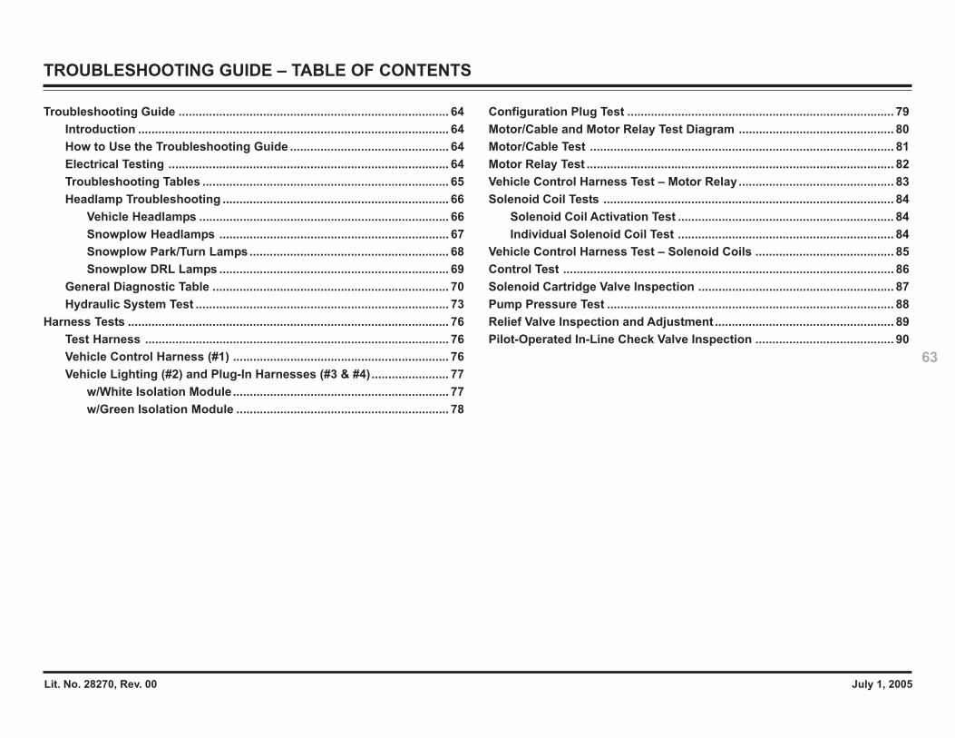
Lit. No. 28270, Rev. 00 July 1, 2005
63
TROUBLESHOOTING GUIDE – TABLE OF CONTENTS
Troubleshooting Guide ................................................................................ 64Introduction ............................................................................................ 64How to Use the Troubleshooting Guide ............................................... 64Electrical Testing ................................................................................... 64Troubleshooting Tables ......................................................................... 65Headlamp Troubleshooting ................................................................... 66
Vehicle Headlamps .......................................................................... 66Snowplow Headlamps .................................................................... 67Snowplow Park/Turn Lamps........................................................... 68Snowplow DRL Lamps .................................................................... 69
General Diagnostic Table ...................................................................... 70Hydraulic System Test ........................................................................... 73
Harness Tests ............................................................................................... 76Test Harness .......................................................................................... 76Vehicle Control Harness (#1) ................................................................ 76Vehicle Lighting (#2) and Plug-In Harnesses (#3 & #4)....................... 77
w/White Isolation Module................................................................ 77w/Green Isolation Module ............................................................... 78
Configuration Plug Test ............................................................................... 79Motor/Cable and Motor Relay Test Diagram .............................................. 80Motor/Cable Test .......................................................................................... 81Motor Relay Test ........................................................................................... 82Vehicle Control Harness Test – Motor Relay.............................................. 83Solenoid Coil Tests ...................................................................................... 84
Solenoid Coil Activation Test ................................................................ 84Individual Solenoid Coil Test ................................................................ 84
Vehicle Control Harness Test – Solenoid Coils ......................................... 85Control Test .................................................................................................. 86Solenoid Cartridge Valve Inspection .......................................................... 87Pump Pressure Test ..................................................................................... 88Relief Valve Inspection and Adjustment ..................................................... 89Pilot-Operated In-Line Check Valve Inspection ......................................... 90
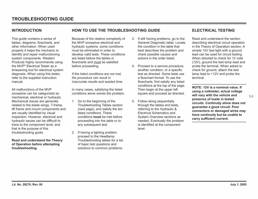
Lit. No. 28270, Rev. 00 July 1, 2005
64
TROUBLESHOOTING GUIDE
INTRODUCTION
This guide contains a series oftables, diagrams, flowcharts, andother information. When usedproperly it helps the mechanic toidentify and repair malfunctioningsystem components. WesternProducts highly recommends usingthe MVP® Electrical Tester as atimesaving tool for electrical systemdiagnosis. When using this tester,refer to the supplied instructionmanual.
All malfunctions of the MVPsnowplow can be categorized asmechanical, electrical or hydraulic.Mechanical issues are generallyrelated to the blade wings, T-frame,lift frame and mount components andare usually identified by visualinspection. However, electrical andhydraulic issues can be difficult totrace to the component level, andthat is the purpose of thistroubleshooting guide.
Read and understand the Theoryof Operation before attemptingtroubleshooting.
Because of the relative complexity ofthe MVP snowplow electrical andhydraulic systems, some conditionsmust be eliminated in order todevelop valid tests. These conditionsare listed before the tables orflowcharts and must be satisfiedbefore proceeding.
If the listed conditions are not met,the procedure can result ininaccurate results and wasted time.
In many cases, satisfying the listedconditions alone solves the problem.
1. Go to the beginning of theTroubleshooting Tables section(next page), and satisfy the tenlisted conditions. Theseconditions must be met beforeproceeding into the table or toany subsequent test.
2. If having a lighting problem,proceed to the HeadlampTroubleshooting tables for a listof basic test questions andsolutions to common problems.
3. If still having problems, go to theGeneral Diagnostic table. Locatethe condition in the table thatbest describes the problem andcheck possible causes andactions in the order listed.
4. Proceed to a service procedure,another condition, or a specifictest as directed. Some tests usea flowchart format. To use theflowcharts, first satisfy any listedconditions at the top of the page.Then begin at the upper leftsquare and proceed as directed.
5. Follow along sequentiallythrough the tables and tests,referring to the Hydraulic &Electrical Schematics andSystem Overview sections asneeded. Eventually the problemis identified at the componentlevel.
ELECTRICAL TESTING
Read and understand the sectiondescribing electrical circuit operationin the Theory of Operation section. Asimple 12V test light with a groundlead can be used for circuit testing.When directed to check for 12 volts(12V), ground the test lamp lead andprobe the terminal. When asked tocheck for ground, attach the testlamp lead to +12V and probe theterminal.
NOTE: 12V is a nominal value. Ifusing a voltmeter, actual voltagewill vary with the vehicle andpresence of loads in testedcircuits. Continuity alone does notguarantee a good circuit. Poorconnectors or damaged wires mayhave continuity but be unable tocarry sufficient current.
HOW TO USE THE TROUBLESHOOTING GUIDE
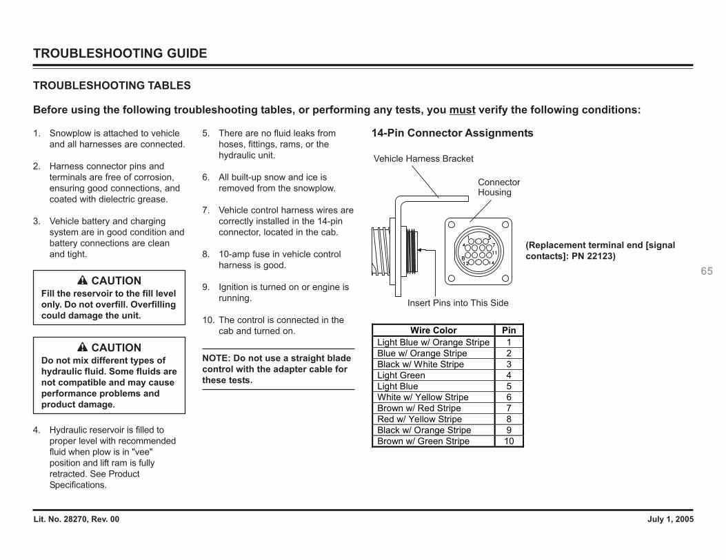
Lit. No. 28270, Rev. 00 July 1, 2005
65
TROUBLESHOOTING GUIDE
TROUBLESHOOTING TABLES
Before using the following troubleshooting tables, or performing any tests, you must verify the following conditions:
1. Snowplow is attached to vehicleand all harnesses are connected.
2. Harness connector pins andterminals are free of corrosion,ensuring good connections, andcoated with dielectric grease.
3. Vehicle battery and chargingsystem are in good condition andbattery connections are cleanand tight.
4. Hydraulic reservoir is filled toproper level with recommendedfluid when plow is in "vee"position and lift ram is fullyretracted. See ProductSpecifications.
5. There are no fluid leaks fromhoses, fittings, rams, or thehydraulic unit.
6. All built-up snow and ice isremoved from the snowplow.
7. Vehicle control harness wires arecorrectly installed in the 14-pinconnector, located in the cab.
8. 10-amp fuse in vehicle controlharness is good.
9. Ignition is turned on or engine isrunning.
10. The control is connected in thecab and turned on.
NOTE: Do not use a straight bladecontrol with the adapter cable forthese tests.
CAUTIONDo not mix different types ofhydraulic fluid. Some fluids arenot compatible and may causeperformance problems andproduct damage.
CAUTIONFill the reservoir to the fill levelonly. Do not overfill. Overfillingcould damage the unit.
Insert Pins into This Side
Vehicle Harness Bracket
ConnectorHousing
Wire Color Pin Light Blue w/ Orange Stripe 1 Blue w/ Orange Stripe 2 Black w/ White Stripe 3 Light Green 4 Light Blue 5 White w/ Yellow Stripe 6 Brown w/ Red Stripe 7 Red w/ Yellow Stripe 8 Black w/ Orange Stripe 9 Brown w/ Green Stripe 10
14-Pin Connector Assignments
(Replacement terminal end [signalcontacts]: PN 22123)
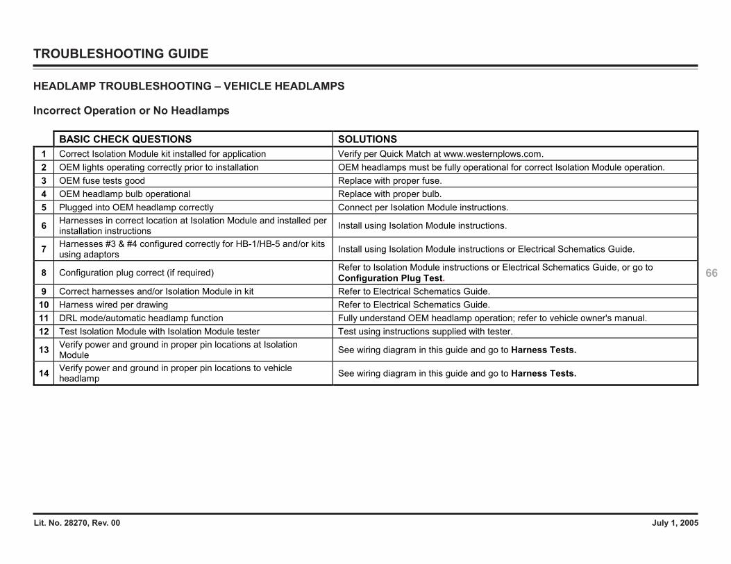
Lit. No. 28270, Rev. 00 July 1, 2005
66
TROUBLESHOOTING GUIDE
HEADLAMP TROUBLESHOOTING – VEHICLE HEADLAMPS
Incorrect Operation or No Headlamps
BASIC CHECK QUESTIONS SOLUTIONS 1 Correct Isolation Module kit installed for application Verify per Quick Match at www.westernplows.com. 2 OEM lights operating correctly prior to installation OEM headlamps must be fully operational for correct Isolation Module operation. 3 OEM fuse tests good Replace with proper fuse. 4 OEM headlamp bulb operational Replace with proper bulb. 5 Plugged into OEM headlamp correctly Connect per Isolation Module instructions.
6 Harnesses in correct location at Isolation Module and installed per installation instructions Install using Isolation Module instructions.
7 Harnesses #3 & #4 configured correctly for HB-1/HB-5 and/or kits using adaptors Install using Isolation Module instructions or Electrical Schematics Guide.
8 Configuration plug correct (if required) Refer to Isolation Module instructions or Electrical Schematics Guide, or go to Configuration Plug Test.
9 Correct harnesses and/or Isolation Module in kit Refer to Electrical Schematics Guide. 10 Harness wired per drawing Refer to Electrical Schematics Guide. 11 DRL mode/automatic headlamp function Fully understand OEM headlamp operation; refer to vehicle owner's manual. 12 Test Isolation Module with Isolation Module tester Test using instructions supplied with tester.
13 Verify power and ground in proper pin locations at Isolation Module See wiring diagram in this guide and go to Harness Tests.
14 Verify power and ground in proper pin locations to vehicle headlamp See wiring diagram in this guide and go to Harness Tests.
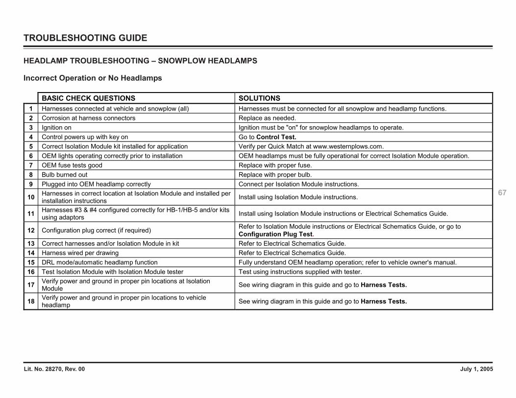
Lit. No. 28270, Rev. 00 July 1, 2005
67
TROUBLESHOOTING GUIDE
HEADLAMP TROUBLESHOOTING – SNOWPLOW HEADLAMPS
Incorrect Operation or No Headlamps
BASIC CHECK QUESTIONS SOLUTIONS 1 Harnesses connected at vehicle and snowplow (all) Harnesses must be connected for all snowplow and headlamp functions. 2 Corrosion at harness connectors Replace as needed. 3 Ignition on Ignition must be "on" for snowplow headlamps to operate. 4 Control powers up with key on Go to Control Test. 5 Correct Isolation Module kit installed for application Verify per Quick Match at www.westernplows.com. 6 OEM lights operating correctly prior to installation OEM headlamps must be fully operational for correct Isolation Module operation. 7 OEM fuse tests good Replace with proper fuse. 8 Bulb burned out Replace with proper bulb. 9 Plugged into OEM headlamp correctly Connect per Isolation Module instructions.
10 Harnesses in correct location at Isolation Module and installed per installation instructions Install using Isolation Module instructions.
11 Harnesses #3 & #4 configured correctly for HB-1/HB-5 and/or kits using adaptors Install using Isolation Module instructions or Electrical Schematics Guide.
12 Configuration plug correct (if required) Refer to Isolation Module instructions or Electrical Schematics Guide, or go to Configuration Plug Test.
13 Correct harnesses and/or Isolation Module in kit Refer to Electrical Schematics Guide. 14 Harness wired per drawing Refer to Electrical Schematics Guide. 15 DRL mode/automatic headlamp function Fully understand OEM headlamp operation; refer to vehicle owner's manual. 16 Test Isolation Module with Isolation Module tester Test using instructions supplied with tester.
17 Verify power and ground in proper pin locations at Isolation Module See wiring diagram in this guide and go to Harness Tests.
18 Verify power and ground in proper pin locations to vehicle headlamp See wiring diagram in this guide and go to Harness Tests.
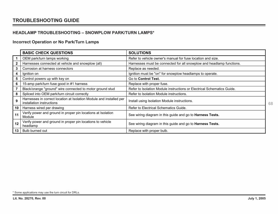
Lit. No. 28270, Rev. 00 July 1, 2005
68
TROUBLESHOOTING GUIDE
HEADLAMP TROUBLESHOOTING – SNOWPLOW PARK/TURN LAMPS*
Incorrect Operation or No Park/Turn Lamps
* Some applications may use the turn circuit for DRLs.
BASIC CHECK QUESTIONS SOLUTIONS 1 OEM park/turn lamps working Refer to vehicle owner's manual for fuse location and size. 2 Harnesses connected at vehicle and snowplow (all) Harnesses must be connected for all snowplow and headlamp functions. 3 Corrosion at harness connectors Replace as needed. 4 Ignition on Ignition must be "on" for snowplow headlamps to operate. 5 Control powers up with key on Go to Control Test. 6 15-amp park/turn fuse good in #1 harness Replace with proper fuse. 7 Black/orange "ground" wire connected to motor ground stud Refer to Isolation Module instructions or Electrical Schematics Guide. 8 Spliced into OEM park/turn circuit correctly Refer to Isolation Module instructions.
9 Harnesses in correct location at Isolation Module and installed per installation instructions Install using Isolation Module instructions.
10 Harness wired per drawing Refer to Electrical Schematics Guide.
11 Verify power and ground in proper pin locations at Isolation Module See wiring diagram in this guide and go to Harness Tests.
12 Verify power and ground in proper pin locations to vehicle headlamp See wiring diagram in this guide and go to Harness Tests.
13 Bulb burned out Replace with proper bulb.
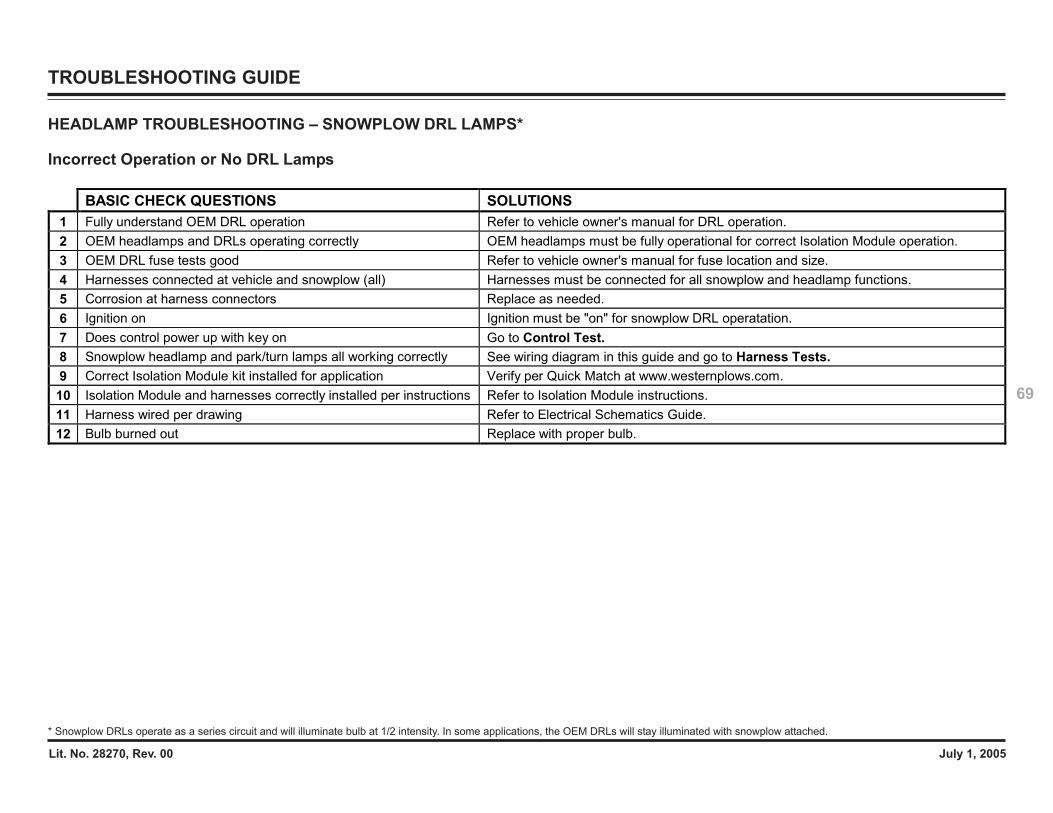
Lit. No. 28270, Rev. 00 July 1, 2005
69
TROUBLESHOOTING GUIDE
HEADLAMP TROUBLESHOOTING – SNOWPLOW DRL LAMPS*
Incorrect Operation or No DRL Lamps
* Snowplow DRLs operate as a series circuit and will illuminate bulb at 1/2 intensity. In some applications, the OEM DRLs will stay illuminated with snowplow attached.
BASIC CHECK QUESTIONS SOLUTIONS 1 Fully understand OEM DRL operation Refer to vehicle owner's manual for DRL operation. 2 OEM headlamps and DRLs operating correctly OEM headlamps must be fully operational for correct Isolation Module operation. 3 OEM DRL fuse tests good Refer to vehicle owner's manual for fuse location and size. 4 Harnesses connected at vehicle and snowplow (all) Harnesses must be connected for all snowplow and headlamp functions. 5 Corrosion at harness connectors Replace as needed. 6 Ignition on Ignition must be "on" for snowplow DRL operatation. 7 Does control power up with key on Go to Control Test. 8 Snowplow headlamp and park/turn lamps all working correctly See wiring diagram in this guide and go to Harness Tests. 9 Correct Isolation Module kit installed for application Verify per Quick Match at www.westernplows.com. 10 Isolation Module and harnesses correctly installed per instructions Refer to Isolation Module instructions. 11 Harness wired per drawing Refer to Electrical Schematics Guide. 12 Bulb burned out Replace with proper bulb.
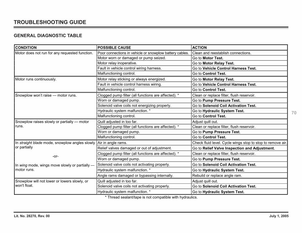
Lit. No. 28270, Rev. 00 July 1, 2005
70
TROUBLESHOOTING GUIDE
CONDITION POSSIBLE CAUSE ACTION Poor connections in vehicle or snowplow battery cables. Clean and reestablish connections. Motor worn or damaged or pump seized. Go to Motor Test. Motor relay inoperative. Go to Motor Relay Test. Fault in vehicle control wiring harness. Go to Vehicle Control Harness Test.
Motor does not run for any requested function.
Malfunctioning control. Go to Control Test. Motor relay sticking or always energized. Go to Motor Relay Test. Fault in vehicle control harness wiring. Go to Vehicle Control Harness Test.
Motor runs continuously.
Malfunctioning control. Go to Control Test. Clogged pump filter (all functions are affected). * Clean or replace filter, flush reservoir. Worn or damaged pump. Go to Pump Pressure Test. Solenoid valve coils not energizing properly. Go to Solenoid Coil Activation Test. Hydraulic system malfunction. * Go to Hydraulic System Test.
Snowplow won’t raise — motor runs.
Malfunctioning control. Go to Control Test. Quill adjusted in too far. Adjust quill out. Clogged pump filter (all functions are affected). * Clean or replace filter, flush reservoir. Worn or damaged pump. Go to Pump Pressure Test.
Snowplow raises slowly or partially — motor runs.
Malfunctioning control. Go to Control Test. Air in angle rams. Check fluid level. Cycle wings stop to stop to remove air. Relief valves damaged or out of adjustment. Go to Relief Valve Inspection and Adjustment. Clogged pump filter (all functions are affected). * Clean or replace filter, flush reservoir. Worn or damaged pump. Go to Pump Pressure Test. Solenoid valve coils not activating properly. Go to Solenoid Coil Activation Test. Hydraulic system malfunction. * Go to Hydraulic System Test.
In straight blade mode, snowplow angles slowly or partially
-or-
In wing mode, wings move slowly or partially — motor runs.
Angle rams damaged or bypassing internally. Rebuild or replace angle ram. Quill adjusted in too far. Adjust quill out. Solenoid valve coils not activating properly. Go to Solenoid Coil Activation Test.
Snowplow will not lower or lowers slowly, or won't float.
Hydraulic system malfunction. * Go to Hydraulic System Test. * Thread sealant/tape is not compatible with hydraulics.
GENERAL DIAGNOSTIC TABLE
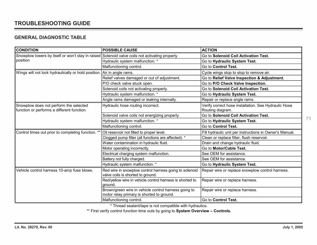
Lit. No. 28270, Rev. 00 July 1, 2005
71
TROUBLESHOOTING GUIDE
CONDITION POSSIBLE CAUSE ACTION Solenoid valve coils not activating properly. Go to Solenoid Coil Activation Test. Hydraulic system malfunction. * Go to Hydraulic System Test.
Snowplow lowers by itself or won’t stay in raised position
Malfunctioning control. Go to Control Test. Air in angle rams. Cycle wings stop to stop to remove air. Relief valves damaged or out of adjustment. Go to Relief Valve Inspection & Adjustment. P/O check valve stuck open. Go to P/O Check Valve Inspection. Solenoid coils not activating properly. Go to Solenoid Coil Activation Test. Hydraulic system malfunction. * Go to Hydraulic System Test.
Wings will not lock hydraulically or hold position.
Angle rams damaged or leaking internally. Repair or replace angle rams. Hydraulic hose routing incorrect. Verify correct hose installation. See Hydraulic Hose
Routing diagram. Solenoid valve coils not energizing properly. Go to Solenoid Coil Activation Test. Hydraulic system malfunction. * Go to Hydraulic System Test.
Snowplow does not perform the selected function or performs a different function.
Malfunctioning control. Go to Control Test. Oil reservoir not filled to proper level. Fill hydraulic unit per instructions in Owner's Manual. Clogged pump filter (all functions are affected). * Clean or replace filter, flush reservoir. Water contamination in hydraulic fluid. Drain and change hydraulic fluid. Motor operating incorrectly. Go to Motor/Cable Test. Electrical charging system malfunction. See OEM for assistance. Battery not fully charged. See OEM for assistance.
Control times out prior to completing function. **
Hydraulic system malfunction. * Go to Hydraulic System Test. Red wire in snowplow control harness going to solenoid valve coils is shorted to ground.
Repair wire or replace snowplow control harness.
Red/yellow wire in vehicle control harness is shorted to ground.
Repair wire or replace harness.
Brown/green wire in vehicle control harness going to motor relay primary is shorted to ground.
Repair wire or replace harness.
Vehicle control harness 10-amp fuse blows.
Malfunctioning control. Go to Control Test. * Thread sealant/tape is not compatible with hydraulics.
** First verify control function time outs by going to System Overview – Controls.
GENERAL DIAGNOSTIC TABLE
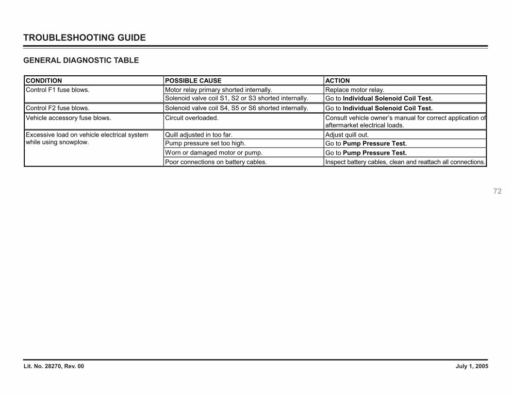
Lit. No. 28270, Rev. 00 July 1, 2005
72
TROUBLESHOOTING GUIDE
GENERAL DIAGNOSTIC TABLE
CONDITION POSSIBLE CAUSE ACTION Motor relay primary shorted internally. Replace motor relay. Control F1 fuse blows. Solenoid valve coil S1, S2 or S3 shorted internally. Go to Individual Solenoid Coil Test.
Control F2 fuse blows. Solenoid valve coil S4, S5 or S6 shorted internally. Go to Individual Solenoid Coil Test. Vehicle accessory fuse blows. Circuit overloaded. Consult vehicle owner’s manual for correct application of
aftermarket electrical loads. Quill adjusted in too far. Adjust quill out. Pump pressure set too high. Go to Pump Pressure Test. Worn or damaged motor or pump. Go to Pump Pressure Test.
Excessive load on vehicle electrical system while using snowplow.
Poor connections on battery cables. Inspect battery cables, clean and reattach all connections.
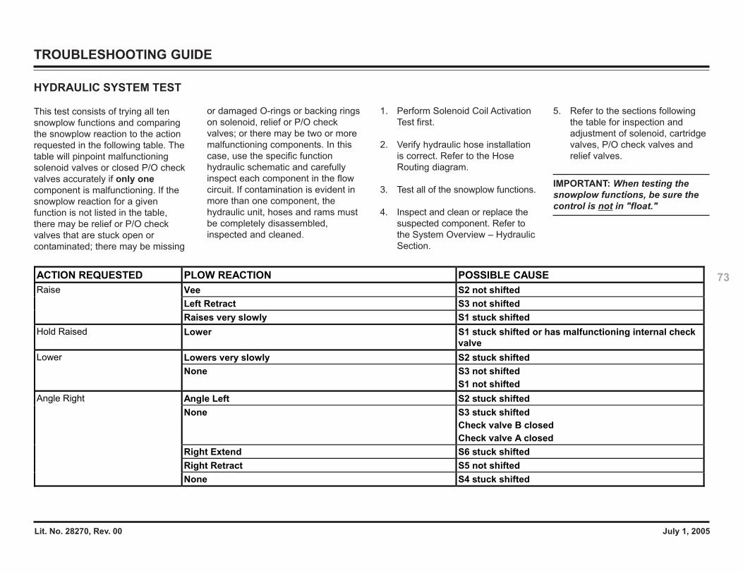
Lit. No. 28270, Rev. 00 July 1, 2005
73
TROUBLESHOOTING GUIDE
HYDRAULIC SYSTEM TEST
This test consists of trying all tensnowplow functions and comparingthe snowplow reaction to the actionrequested in the following table. Thetable will pinpoint malfunctioningsolenoid valves or closed P/O checkvalves accurately if only onecomponent is malfunctioning. If thesnowplow reaction for a givenfunction is not listed in the table,there may be relief or P/O checkvalves that are stuck open orcontaminated; there may be missing
or damaged O-rings or backing ringson solenoid, relief or P/O checkvalves; or there may be two or moremalfunctioning components. In thiscase, use the specific functionhydraulic schematic and carefullyinspect each component in the flowcircuit. If contamination is evident inmore than one component, thehydraulic unit, hoses and rams mustbe completely disassembled,inspected and cleaned.
1. Perform Solenoid Coil ActivationTest first.
2. Verify hydraulic hose installationis correct. Refer to the HoseRouting diagram.
3. Test all of the snowplow functions.
4. Inspect and clean or replace thesuspected component. Refer tothe System Overview – HydraulicSection.
5. Refer to the sections followingthe table for inspection andadjustment of solenoid, cartridgevalves, P/O check valves andrelief valves.
IMPORTANT: When testing thesnowplow functions, be sure thecontrol is not in "float."
ACTION REQUESTED PLOW REACTION POSSIBLE CAUSE Vee S2 not shifted Left Retract S3 not shifted
Raise
Raises very slowly S1 stuck shifted Hold Raised Lower S1 stuck shifted or has malfunctioning internal check
valve Lowers very slowly S2 stuck shifted Lower None S3 not shifted
S1 not shifted Angle Left S2 stuck shifted None S3 stuck shifted
Check valve B closed Check valve A closed
Right Extend S6 stuck shifted Right Retract S5 not shifted
Angle Right
None S4 stuck shifted
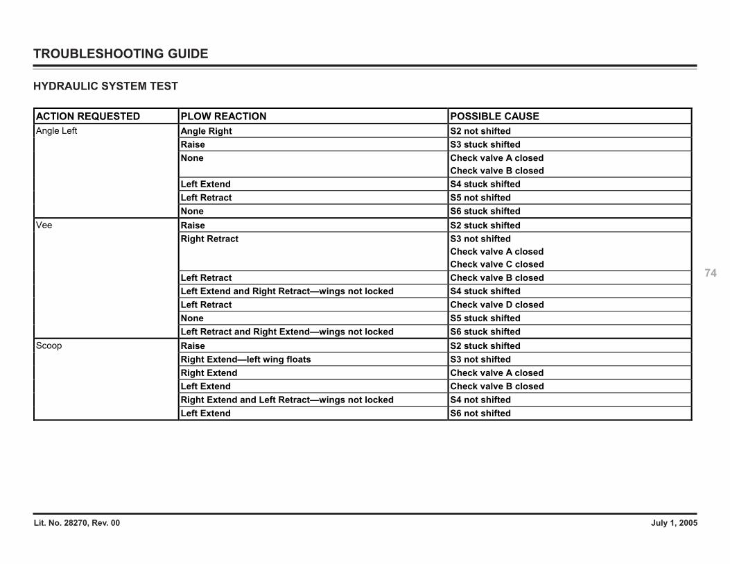
Lit. No. 28270, Rev. 00 July 1, 2005
74
TROUBLESHOOTING GUIDE
ACTION REQUESTED PLOW REACTION POSSIBLE CAUSE Angle Right S2 not shifted Raise S3 stuck shifted None Check valve A closed
Check valve B closed Left Extend S4 stuck shifted Left Retract S5 not shifted
Angle Left
None S6 stuck shifted Raise S2 stuck shifted Right Retract S3 not shifted
Check valve A closed Check valve C closed
Left Retract Check valve B closed Left Extend and Right Retract—wings not locked S4 stuck shifted Left Retract Check valve D closed None S5 stuck shifted
Vee
Left Retract and Right Extend—wings not locked S6 stuck shifted Raise S2 stuck shifted Right Extend—left wing floats S3 not shifted Right Extend Check valve A closed Left Extend Check valve B closed Right Extend and Left Retract—wings not locked S4 not shifted
Scoop
Left Extend S6 not shifted
HYDRAULIC SYSTEM TEST
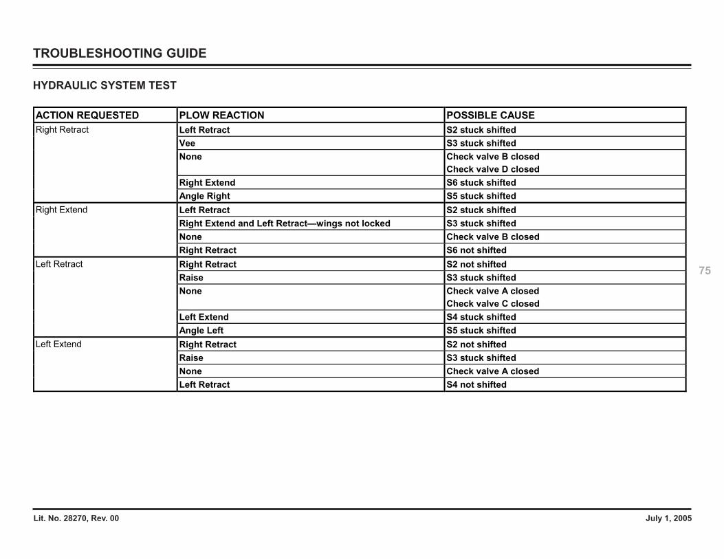
Lit. No. 28270, Rev. 00 July 1, 2005
75
TROUBLESHOOTING GUIDE
ACTION REQUESTED PLOW REACTION POSSIBLE CAUSE Left Retract S2 stuck shifted Vee S3 stuck shifted None Check valve B closed
Check valve D closed Right Extend S6 stuck shifted
Right Retract
Angle Right S5 stuck shifted Left Retract S2 stuck shifted Right Extend and Left Retract—wings not locked S3 stuck shifted None Check valve B closed
Right Extend
Right Retract S6 not shifted Right Retract S2 not shifted Raise S3 stuck shifted None Check valve A closed
Check valve C closed Left Extend S4 stuck shifted
Left Retract
Angle Left S5 stuck shifted Right Retract S2 not shifted Raise S3 stuck shifted None Check valve A closed
Left Extend
Left Retract S4 not shifted
HYDRAULIC SYSTEM TEST
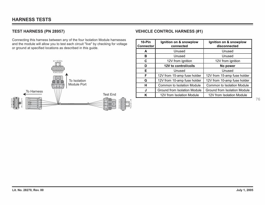
Lit. No. 28270, Rev. 00 July 1, 2005
76
HARNESS TESTS
10-Pin Connector
Ignition on & snowplow connected
Ignition on & snowplow disconnected
A Unused Unused B Unused Unused C 12V from ignition 12V from ignition D 12V to control/coils No power E Unused Unused F 12V from 15-amp fuse holder 12V from 15-amp fuse holder G 12V from 10-amp fuse holder 12V from 10-amp fuse holder H Common to Isolation Module Common to Isolation Module J Ground from Isolation Module Ground from Isolation Module K 12V from Isolation Module 12V from Isolation Module
VEHICLE CONTROL HARNESS (#1)TEST HARNESS (PN 28957)
Connecting this harness between any of the four Isolation Module harnessesand the module will allow you to test each circuit "live" by checking for voltageor ground at specified locations as described in this guide.
A K
E
CB
DF
HJ
G
AC
BE
D
A C D EB
G FHJK
A
CDE
B
GF
HJK
To Harness
To IsolationModule Port
Test End
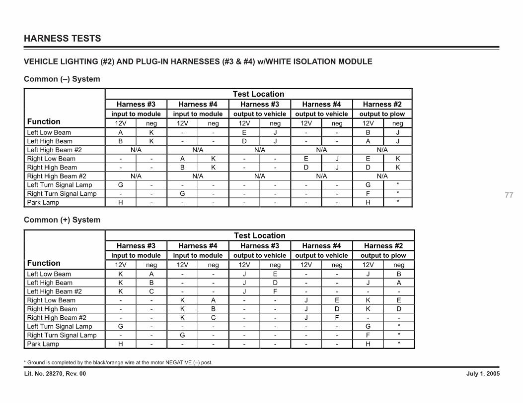
Lit. No. 28270, Rev. 00 July 1, 2005
77
HARNESS TESTS
VEHICLE LIGHTING (#2) AND PLUG-IN HARNESSES (#3 & #4) w/WHITE ISOLATION MODULE
Common (–) System
Common (+) System
Test Location Harness #3 Harness #4 Harness #3 Harness #4 Harness #2
input to module input to module output to vehicle output to vehicle output to plow Function 12V neg 12V neg 12V neg 12V neg 12V neg Left Low Beam A K - - E J - - B J Left High Beam B K - - D J - - A J Left High Beam #2 N/A N/A N/A N/A N/A Right Low Beam - - A K - - E J E K Right High Beam - - B K - - D J D K Right High Beam #2 N/A N/A N/A N/A N/A Left Turn Signal Lamp G - - - - - - - G * Right Turn Signal Lamp - - G - - - - - F * Park Lamp H - - - - - - - H *
Test Location Harness #3 Harness #4 Harness #3 Harness #4 Harness #2
input to module input to module output to vehicle output to vehicle output to plow Function 12V neg 12V neg 12V neg 12V neg 12V neg Left Low Beam K A - - J E - - J B Left High Beam K B - - J D - - J A Left High Beam #2 K C - - J F - - - - Right Low Beam - - K A - - J E K E Right High Beam - - K B - - J D K D Right High Beam #2 - - K C - - J F - - Left Turn Signal Lamp G - - - - - - - G * Right Turn Signal Lamp - - G - - - - - F * Park Lamp H - - - - - - - H *
* Ground is completed by the black/orange wire at the motor NEGATIVE (–) post.
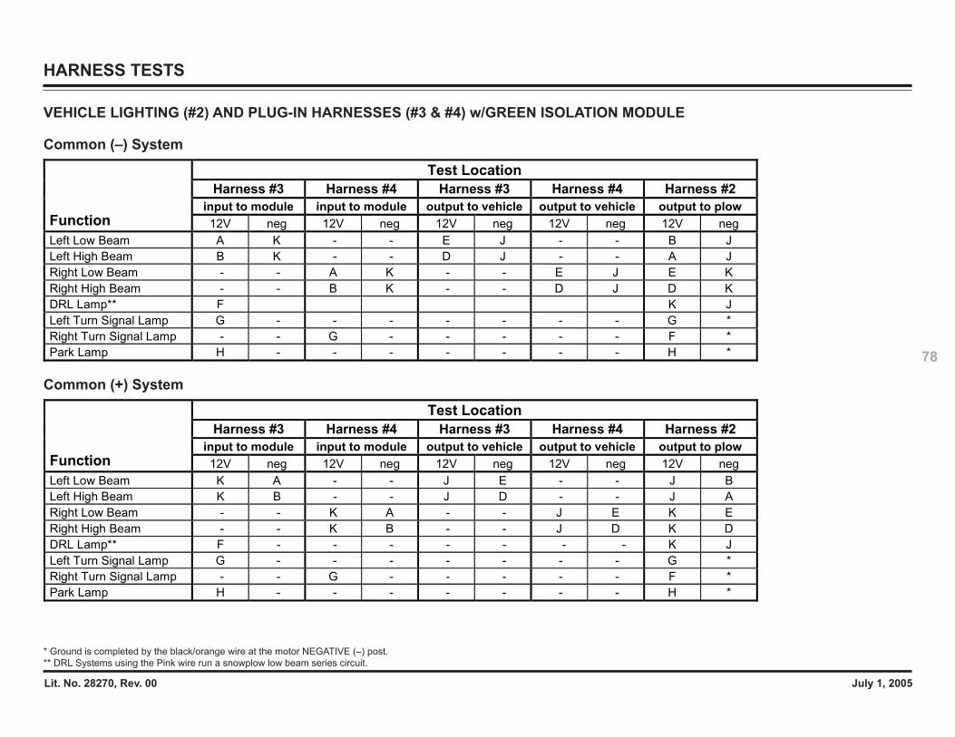
Lit. No. 28270, Rev. 00 July 1, 2005
78
HARNESS TESTS
VEHICLE LIGHTING (#2) AND PLUG-IN HARNESSES (#3 & #4) w/GREEN ISOLATION MODULE
Common (–) System
Common (+) System
Test Location Harness #3 Harness #4 Harness #3 Harness #4 Harness #2
input to module input to module output to vehicle output to vehicle output to plow Function 12V neg 12V neg 12V neg 12V neg 12V neg Left Low Beam A K - - E J - - B J Left High Beam B K - - D J - - A J Right Low Beam - - A K - - E J E K Right High Beam - - B K - - D J D K DRL Lamp** F K J Left Turn Signal Lamp G - - - - - - - G * Right Turn Signal Lamp - - G - - - - - F * Park Lamp H - - - - - - - H *
Test Location Harness #3 Harness #4 Harness #3 Harness #4 Harness #2
input to module input to module output to vehicle output to vehicle output to plow Function 12V neg 12V neg 12V neg 12V neg 12V neg Left Low Beam K A - - J E - - J B Left High Beam K B - - J D - - J A Right Low Beam - - K A - - J E K E Right High Beam - - K B - - J D K D DRL Lamp** F - - - - - - - K J Left Turn Signal Lamp G - - - - - - - G * Right Turn Signal Lamp - - G - - - - - F * Park Lamp H - - - - - - - H *
* Ground is completed by the black/orange wire at the motor NEGATIVE (–) post.** DRL Systems using the Pink wire run a snowplow low beam series circuit.

Lit. No. 28270, Rev. 00 July 1, 2005
79
CONFIGURATION PLUG TEST
1. Remove configuration plug.
12
15 Amp Fuse (Park/Turn)
10 Amp Fuse (Control)
Cavity Plug
Configuration Plug
Wire Side Views
BC
A
BC
A(Blue)
(Blue/White)
(Blue/Red)
Using a flat-bladed screwdriver, jump
between terminals B and A of the
configuration plug mating connector.
Does the left low beam illuminate?
NO
YESReplace configuration plug.
Jump between terminals B and C of
the configuration plug mating
connector. Does the left low beam
illuminate?
YES
NO
Go to Harness Tests – Vehicle
Control Harness (#1)
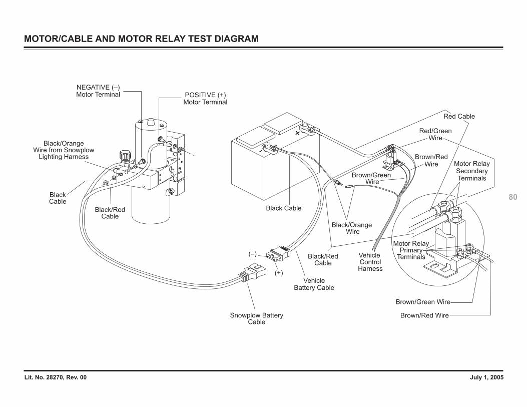
Lit. No. 28270, Rev. 00 July 1, 2005
80
MOTOR/CABLE AND MOTOR RELAY TEST DIAGRAM
-
+
POSITIVE (+) Motor Terminal
NEGATIVE (–) Motor Terminal
Black/RedCable
Black/OrangeWire from Snowplow
Lighting Harness
Snowplow Battery Cable
BlackCable
Vehicle ControlHarness
Motor Relay Primary
Terminals
Vehicle Battery Cable
Red Cable
Brown/Red Wire
Black Cable
Brown/Green Wire
Black/Orange Wire
Black/RedCable
Motor Relay SecondaryTerminals
Brown/RedWire
Red/Green Wire
Brown/Green Wire
(–)
(+)
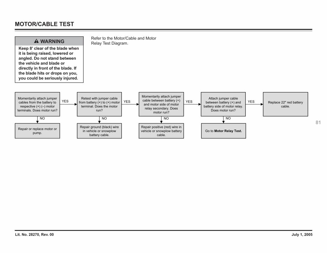
Lit. No. 28270, Rev. 00 July 1, 2005
81
MOTOR/CABLE TEST
WARNINGKeep 8' clear of the blade whenit is being raised, lowered orangled. Do not stand betweenthe vehicle and blade ordirectly in front of the blade. Ifthe blade hits or drops on you,you could be seriously injured.
Refer to the Motor/Cable and MotorRelay Test Diagram.
Repair or replace motor or
pump.
Momentarily attach jumper
cables from the battery to
respective (+) (–) motor
terminals. Does motor run?
Retest with jumper cable
from battery (+) to (+) motor
terminal. Does the motor
run?
Repair ground (black) wire
in vehicle or snowplow
battery cable.
Momentarily attach jumper
cable between battery (+)
and motor side of motor
relay secondary. Does
motor run?
Repair positive (red) wire in
vehicle or snowplow battery
cable.
NO NO NO
YES YESYESAttach jumper cable
between battery (+) and
battery side of motor relay.
Does motor run?
Go to Motor Relay Test.
NO
Replace 22" red battery
cable.
YES
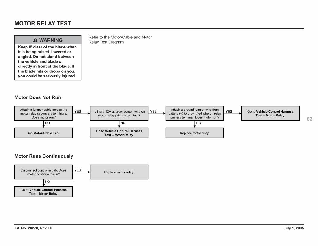
Lit. No. 28270, Rev. 00 July 1, 2005
82
MOTOR RELAY TEST
WARNINGKeep 8' clear of the blade whenit is being raised, lowered orangled. Do not stand betweenthe vehicle and blade ordirectly in front of the blade. Ifthe blade hits or drops on you,you could be seriously injured.
Refer to the Motor/Cable and MotorRelay Test Diagram.
Motor Does Not Run
Motor Runs Continuously
Go to Vehicle Control Harness
Test – Motor Relay.
Attach a jumper cable across the
motor relay secondary terminals.
Does motor run?
See Motor/Cable Test.
NO
YES Is there 12V at brown/green wire on
motor relay primary terminal?
Go to Vehicle Control Harness
Test – Motor Relay.
NO
YESAttach a ground jumper wire from
battery (–) to brown/red wire on relay
primary terminal. Does motor run?
Replace motor relay.
NO
YES
Disconnect control in cab. Does
motor continue to run?
Go to Vehicle Control Harness
Test – Motor Relay.
NO
YESReplace motor relay.
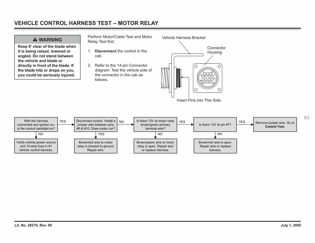
Lit. No. 28270, Rev. 00 July 1, 2005
83
VEHICLE CONTROL HARNESS TEST – MOTOR RELAY
WARNINGKeep 8' clear of the blade whenit is being raised, lowered orangled. Do not stand betweenthe vehicle and blade ordirectly in front of the blade. Ifthe blade hits or drops on you,you could be seriously injured.
Perform Motor/Cable Test and MotorRelay Test first.
1. Disconnect the control in thecab.
2. Refer to the 14-pin Connectordiagram. Test the vehicle side ofthe connector in the cab asfollows.
Insert Pins into This Side
Vehicle Harness Bracket
ConnectorHousing
Verify vehicle power source
and 10-amp fuse in #1
vehicle control harness.
With the harness
connected and ignition on,
is the control backlight on?
Disconnect control. Install a
jumper wire between pins
#8 & #10. Does motor run?
Brown/red wire to motor
relay is shorted to ground.
Repair wire.
Is there 12V at motor relay
brown/green primary
terminal wire?
Brown/green wire to motor
relay is open. Repair wire
or replace harness.
NO YES NO
NO YESYESIs there 12V at pin #7?
Brown/red wire is open.
Repair wire or replace
harness.
NO
Remove jumper wire. Go to
Control Test.
YES
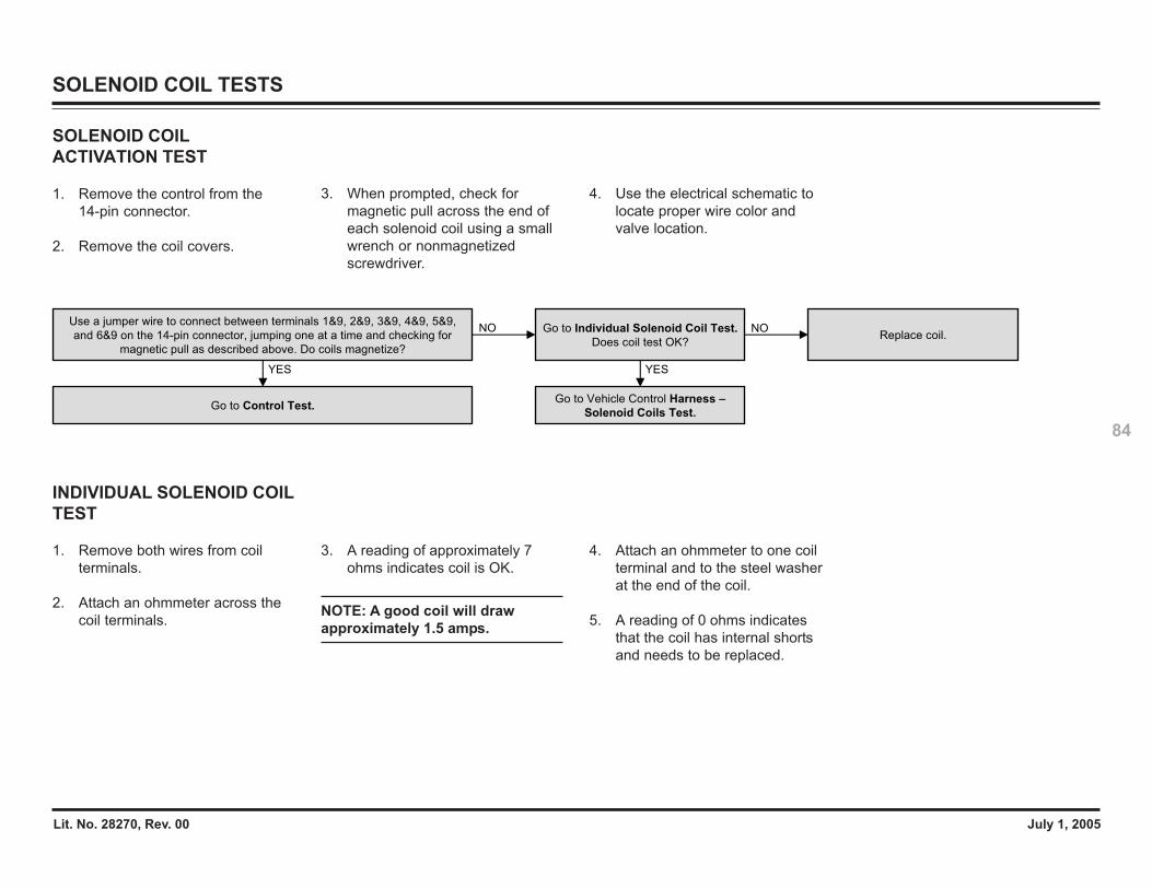
Lit. No. 28270, Rev. 00 July 1, 2005
84
SOLENOID COIL TESTS
SOLENOID COILACTIVATION TEST
1. Remove the control from the14-pin connector.
2. Remove the coil covers.
3. When prompted, check formagnetic pull across the end ofeach solenoid coil using a smallwrench or nonmagnetizedscrewdriver.
4. Use the electrical schematic tolocate proper wire color andvalve location.
Replace coil.
Use a jumper wire to connect between terminals 1&9, 2&9, 3&9, 4&9, 5&9,
and 6&9 on the 14-pin connector, jumping one at a time and checking for
magnetic pull as described above. Do coils magnetize?
Go to Control Test.
YES
NO Go to Individual Solenoid Coil Test.
Does coil test OK?
Go to Vehicle Control Harness –
Solenoid Coils Test.
YES
NO
INDIVIDUAL SOLENOID COILTEST
1. Remove both wires from coilterminals.
2. Attach an ohmmeter across thecoil terminals.
3. A reading of approximately 7ohms indicates coil is OK.
NOTE: A good coil will drawapproximately 1.5 amps.
4. Attach an ohmmeter to one coilterminal and to the steel washerat the end of the coil.
5. A reading of 0 ohms indicatesthat the coil has internal shortsand needs to be replaced.
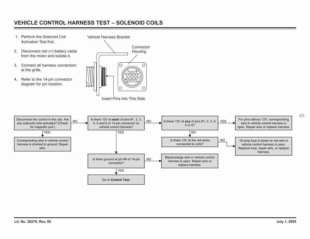
Lit. No. 28270, Rev. 00 July 1, 2005
85
VEHICLE CONTROL HARNESS TEST – SOLENOID COILS
1. Perform the Solenoid CoilActivation Test first.
2. Disconnect red (+) battery cablefrom the motor and isolate it.
3. Connect all harness connectorsat the grille.
4, Refer to the 14-pin connectordiagram for pin location.
Insert Pins into This Side
Vehicle Harness Bracket
ConnectorHousing
YES
NO
YES
NOFor pins without 12V, corresponding
wire in vehicle control harness is
open. Repair wire or replace harness.
Disconnect the control in the cab. Are
any solenoid coils activated? (Check
for magnetic pull.)
Is there 12V at each of pins #1, 2, 3,
4, 5 and 6 of 14-pin connector on
vehicle control harness?
Is there 12V at any of pins #1, 2, 3, 4,
5 or 6?
Corresponding wire in vehicle control
harness is shorted to ground. Repair
wire.
Is there 12V at the red wires
connected to coils?
NO
YES
NOIs there ground at pin #9 of 14-pin
connector?
Black/orange wire in vehicle control
harness is open. Repair wire or
replace harness.
YES
Go to Control Test.
10-amp fuse is blown or red wire in
vehicle control harness is open.
Replace fuse, repair wire, or replace
harness.
NO
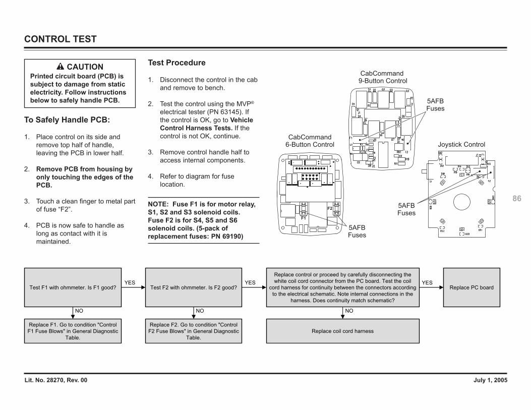
Lit. No. 28270, Rev. 00 July 1, 2005
86
CONTROL TEST
CAUTIONPrinted circuit board (PCB) issubject to damage from staticelectricity. Follow instructionsbelow to safely handle PCB.
To Safely Handle PCB:
1. Place control on its side andremove top half of handle,leaving the PCB in lower half.
2. Remove PCB from housing byonly touching the edges of thePCB.
3. Touch a clean finger to metal partof fuse “F2”.
4. PCB is now safe to handle aslong as contact with it ismaintained.
Test Procedure
1. Disconnect the control in the caband remove to bench.
2. Test the control using the MVP®
electrical tester (PN 63145). Ifthe control is OK, go to VehicleControl Harness Tests. If thecontrol is not OK, continue.
3. Remove control handle half toaccess internal components.
4. Refer to diagram for fuselocation.
NOTE: Fuse F1 is for motor relay,S1, S2 and S3 solenoid coils.Fuse F2 is for S4, S5 and S6solenoid coils. (5-pack ofreplacement fuses: PN 69190)
5AFB Fuses
Joystick Control
5AFB Fuses
CabCommand 9-Button Control
F1
F2
5AFB Fuses
CabCommand 6-Button Control
Replace PC boardTest F1 with ohmmeter. Is F1 good?
Replace F1. Go to condition "Control
F1 Fuse Blows" in General Diagnostic
Table.
NO
YESTest F2 with ohmmeter. Is F2 good?
Replace F2. Go to condition "Control
F2 Fuse Blows" in General Diagnostic
Table.
NO
YES
Replace control or proceed by carefully disconnecting the
white coil cord connector from the PC board. Test the coil
cord harness for continuity between the connectors according
to the electrical schematic. Note internal connections in the
harness. Does continuity match schematic?
Replace coil cord harness
NO
YES
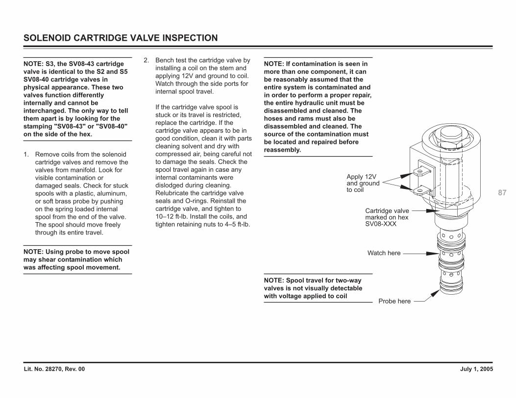
Lit. No. 28270, Rev. 00 July 1, 2005
87
SOLENOID CARTRIDGE VALVE INSPECTION
NOTE: S3, the SV08-43 cartridgevalve is identical to the S2 and S5SV08-40 cartridge valves inphysical appearance. These twovalves function differentlyinternally and cannot beinterchanged. The only way to tellthem apart is by looking for thestamping "SV08-43" or "SV08-40"on the side of the hex.
1. Remove coils from the solenoidcartridge valves and remove thevalves from manifold. Look forvisible contamination ordamaged seals. Check for stuckspools with a plastic, aluminum,or soft brass probe by pushingon the spring loaded internalspool from the end of the valve.The spool should move freelythrough its entire travel.
NOTE: Using probe to move spoolmay shear contamination whichwas affecting spool movement.
2. Bench test the cartridge valve byinstalling a coil on the stem andapplying 12V and ground to coil.Watch through the side ports forinternal spool travel.
If the cartridge valve spool isstuck or its travel is restricted,replace the cartridge. If thecartridge valve appears to be ingood condition, clean it with partscleaning solvent and dry withcompressed air, being careful notto damage the seals. Check thespool travel again in case anyinternal contaminants weredislodged during cleaning.Relubricate the cartridge valveseals and O-rings. Reinstall thecartridge valve, and tighten to10–12 ft-lb. Install the coils, andtighten retaining nuts to 4–5 ft-lb.
NOTE: If contamination is seen inmore than one component, it canbe reasonably assumed that theentire system is contaminated andin order to perform a proper repair,the entire hydraulic unit must bedisassembled and cleaned. Thehoses and rams must also bedisassembled and cleaned. Thesource of the contamination mustbe located and repaired beforereassembly.
NOTE: Spool travel for two-wayvalves is not visually detectablewith voltage applied to coil
Apply 12V and ground to coil
Cartridge valve marked on hexSV08-XXX
Watch here
Probe here
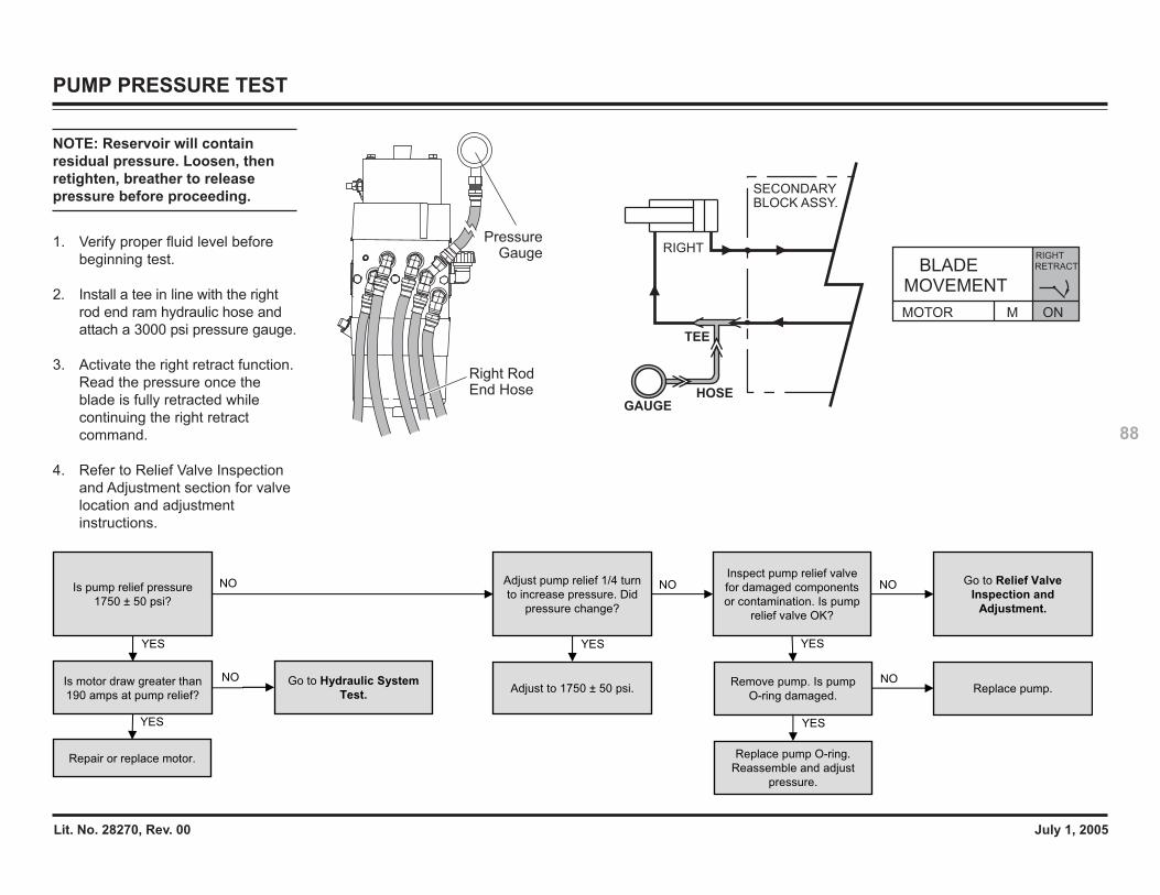
Lit. No. 28270, Rev. 00 July 1, 2005
88
PUMP PRESSURE TEST
NOTE: Reservoir will containresidual pressure. Loosen, thenretighten, breather to releasepressure before proceeding.
1. Verify proper fluid level beforebeginning test.
2. Install a tee in line with the rightrod end ram hydraulic hose andattach a 3000 psi pressure gauge.
3. Activate the right retract function.Read the pressure once theblade is fully retracted whilecontinuing the right retractcommand.
4. Refer to Relief Valve Inspectionand Adjustment section for valvelocation and adjustmentinstructions.
Is motor draw greater than
190 amps at pump relief?
Is pump relief pressure
1750 ± 50 psi?
Adjust pump relief 1/4 turn
to increase pressure. Did
pressure change?
Adjust to 1750 ± 50 psi.
YES YES
NONOInspect pump relief valve
for damaged components
or contamination. Is pump
relief valve OK?
Remove pump. Is pump
O-ring damaged.
YES
Go to Relief Valve
Inspection and
Adjustment.
NO
Replace pump.
Replace pump O-ring.
Reassemble and adjust
pressure.
YES
NONO
YES
Repair or replace motor.
Go to Hydraulic System
Test.
Right Rod End Hose
PressureGauge RIGHT
SECONDARYBLOCK ASSY.
HOSEGAUGE
TEE
MOVEMENTBLADE
RIGHT
RETRACT
MOTOR M ON
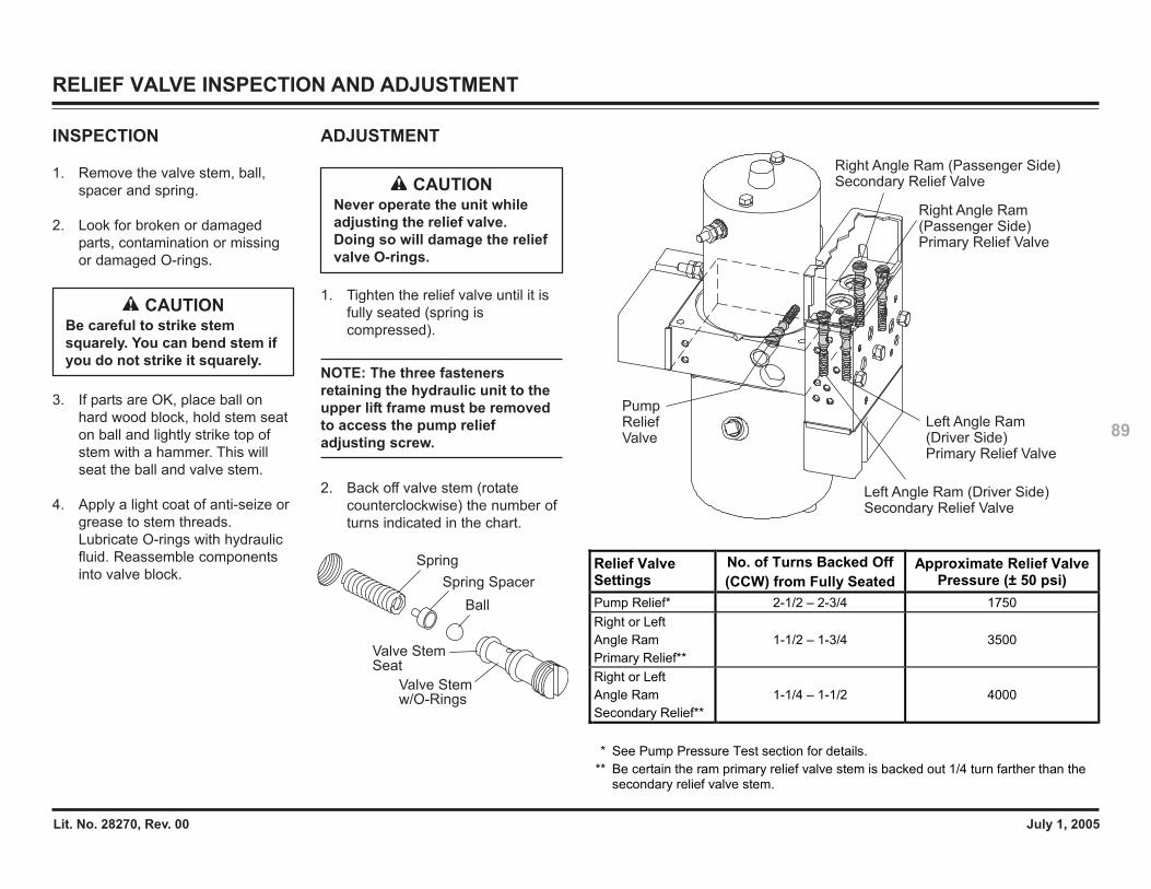
Lit. No. 28270, Rev. 00 July 1, 2005
89
RELIEF VALVE INSPECTION AND ADJUSTMENT
INSPECTION
1. Remove the valve stem, ball,spacer and spring.
2. Look for broken or damagedparts, contamination or missingor damaged O-rings.
3. If parts are OK, place ball onhard wood block, hold stem seaton ball and lightly strike top ofstem with a hammer. This willseat the ball and valve stem.
4. Apply a light coat of anti-seize orgrease to stem threads.Lubricate O-rings with hydraulicfluid. Reassemble componentsinto valve block.
ADJUSTMENT
1. Tighten the relief valve until it isfully seated (spring iscompressed).
NOTE: The three fastenersretaining the hydraulic unit to theupper lift frame must be removedto access the pump reliefadjusting screw.
2. Back off valve stem (rotatecounterclockwise) the number ofturns indicated in the chart.
CAUTIONBe careful to strike stemsquarely. You can bend stem ifyou do not strike it squarely.
Spring
Spring Spacer
Ball
Valve Stem w/O-Rings
Valve StemSeat
CAUTIONNever operate the unit whileadjusting the relief valve.Doing so will damage the reliefvalve O-rings.
Pump ReliefValve
Right Angle Ram (Passenger Side)Secondary Relief Valve
Right Angle Ram (Passenger Side)Primary Relief Valve
Left Angle Ram(Driver Side)Primary Relief Valve
Left Angle Ram (Driver Side)Secondary Relief Valve
Relief Valve Settings
No. of Turns Backed Off (CCW) from Fully Seated
Approximate Relief Valve Pressure (± 50 psi)
Pump Relief* 2-1/2 – 2-3/4 1750 Right or Left Angle Ram Primary Relief**
1-1/2 – 1-3/4 3500
Right or Left Angle Ram Secondary Relief**
1-1/4 – 1-1/2 4000
* See Pump Pressure Test section for details. ** Be certain the ram primary relief valve stem is backed out 1/4 turn farther than the
secondary relief valve stem.
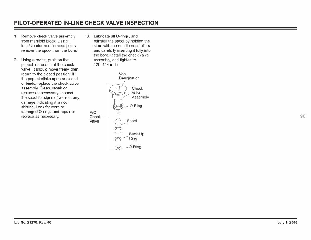
Lit. No. 28270, Rev. 00 July 1, 2005
90
PILOT-OPERATED IN-LINE CHECK VALVE INSPECTION
1. Remove check valve assemblyfrom manifold block. Usinglong/slender needle nose pliers,remove the spool from the bore.
2. Using a probe, push on thepoppet in the end of the checkvalve. It should move freely, thenreturn to the closed position. Ifthe poppet sticks open or closedor binds, replace the check valveassembly. Clean, repair orreplace as necessary. Inspectthe spool for signs of wear or anydamage indicating it is notshifting. Look for worn ordamaged O-rings and repair orreplace as necessary.
3. Lubricate all O-rings, andreinstall the spool by holding thestem with the needle nose pliersand carefully inserting it fully intothe bore. Install the check valveassembly, and tighten to120–144 in-lb.
CheckValveAssembly
VeeDesignation
Spool
Back-UpRing
O-Ring
P/OCheck Valve
O-Ring


Lit. No. 28270, Rev. 00 July 1, 2005
92
WESTERN PRODUCTSP.O. BOX 245038MILWAUKEE, WI 53224-9538
A DIVISION OF DOUGLAS DYNAMICS, L.L.C.
Copyright © 2005 Douglas Dynamics, L.L.C. All rights reserved. This material may not be reproduced or copied, in whole or in part, in any printed, mechanical, electronic, film or other distribution and storagemedia, without the written consent of Western Products. Authorization to photocopy items for internal or personal use by Western Products outlets or snowplow owner is granted.
Western Products reserves the right under its product improvement policy to change construction or design details and furnish equipment when so altered without reference to illustrations or specificationsused. Western Products and the vehicle manufacturer may require and/or recommend optional equipment for snow removal. Do not exceed vehicle ratings with a snowplow. This product is manufactured underthe following US patents: 4,999,935; 5,420,480; 6,145,222; 6,209,231; 6,253,470; 6,526,677; RE 35,700; CAN patent 2,060,425 and other patents pending. Western Products offers a limited warranty for allsnowplows and accessories. See separately printed page for this important information. The following are registered (®) trademarks of Douglas Dynamics, L.L.C.: FloStat®, MVP®, UltraMount®, WESTERN®.
Printed in U.S.A.


![2Untitled [library.westernplows.com]library.westernplows.com/westernplows/pdffiles/13523_080092.pdf · Title: 2Untitled.pdf Created Date: 10/15/2002 5:56:09 PM](https://img.pdfslide.us/doc/110x75/5c48c4b193f3c350ba78f3c1/2untitled-title-2untitledpdf-created-date-10152002-55609-pm.jpg)