Embed Size (px)
Citation preview

TOYOTA TUNDRA 2014 - SUPERCHARGER FIT KIT Preparation
Page 1 of 67 pages DIOIssue: A 06/26/2014
READ THIS IMPORTANT NOTICE BEFORE INSTALLING THE TRD SUPERCHARGER SYSTEM. The TRD Supercharger System requires a special calibration that needs to be installed into the OEM ECU. The supercharger calibration is unique for each model variation and cannot be interchanged. NOT ALL MODELS ARE ELIGIBLE FOR A SUPERCHARGER SYSTEM! Do not install the TRD Supercharger System until the OE vehicle calibration ID can be verified, and a Supercharger Calibration exists for your vehicle. *Ensure you have the latest set of installation instructions. The latest set of instructions can be downloaded through TIS, or may be obtained through your local Toyota Dealer. Check the OE Calibration ID of the vehicle that will have a TRD Supercharger System installed. Refer to T-SB-0012-13 “Techstream ECU Flash Reprogramming Procedure”. Verify that a Supercharger Calibration exists before proceeding with the installation. Compare the OE Calibration ID with the Supercharger Calibration chart near the end of these instructions. If the OE calibration IS NOT LISTED in the Target Calibration ID table, DO NOT INSTALL THE SUPERCHARGER SYSTEM! Calibrations not listed on the Target Calibration ID Table will result in a “No Flash” condition! Refer to ASG or your Toyota Dealer for updated information regarding available supercharger calibrations.
WARNING! – DO NOT INSTALL THE TRD SUPERCHARGER CALIBRATION FILE INTO A VEHICLE THAT WILL NOT HAVE A SUPERCHARGER SYSTEM INSTALLED. Installation of the TRD Supercharger calibration file is NON-REVERSABLE! Installation of a TRD supercharger calibration into a non-supercharged equipped vehicle will result in multiple malfunction codes. A supercharger calibration cannot be removed once the ECU has been programmed. Replacement of the ECU will be required if an OE calibration is needed. Neither Toyota Motor Sales, USA, Inc. nor TRD will honor any warranty claim in which a non-supercharged vehicle was unintentionally programmed with a supercharger calibration. TRD supercharger systems are only calibrated to operate on PREMIUM Gasoline (91 Octane or higher Unleaded Fuel) R+M / 2 method. Use of Flex-Fuels or Gasoline with more than 10% Ethanol is not approved.
Emissions Compliance Information: A new process has been implemented. No longer is the Emissions Label included in the Supercharger Fit Kit. If your state requires an Emissions Compliance Label, one may be ordered through your Toyota dealer or the Toyota Materials Distribution Center (MDC) 310-468-9800 or [email protected] This TRD Supercharger Kit has received 50-State Emissions Compliance via the California Air Resources Board (CARB). Not all states require the Emissions Compliance Label but TRD does recommend ordering one. To receive the proper Supercharger Emissions Compliance Label for this TRD Supercharger kit, please order MDC label part number 00602-34155. Proof of ownership may be required.
TOYOTA TUNDRA 2014 - SUPERCHARGER FIT KIT Preparation
Page 2 of 67 pages DIOIssue: A 06/26/2014
#1
#2 #3
A18
A5
A1
A4
A3
A2
A6A7
A8 A9A10
A11
A12
A13
A17
A14
A15
A16
A19
A20A21
#4
Coolant Crossover Manifold
TRD Air Filter & Air Box Lid
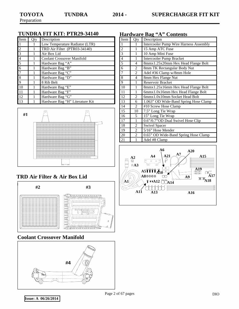
TUNDRA FIT KIT: PTR29-34140 Item Qty Description 1 1 Low Temperature Radiator (LTR) 2 1 TRD Air Filter (PTR03-34140) 3 1 Air Box Lid 4 1 Coolant Crossover Manifold 5 1 Hardware Bag “A” 6 1 Hardware Bag “B” 7 1 Hardware Bag “C” 8 1 Hardware Bag “D” 9 1 8 Rib Belt 10 1 Hardware Bag “E” 11 1 Hardware Bag “F” 12 1 Hardware Bag “G” 13 1 Hardware Bag “H” Literature Kit
Hardware Bag “A” Contents Item Qty Description 1 1 Intercooler Pump Wire Harness Assembly 2 1 15 Amp ATC Fuse 3 1 10 Amp Mini Fuse 4 1 Intercooler Pump Bracket 5 4 8mmx1.25x20mm Hex Head Flange Bolt 6 2 8mm TK Rectangular Body Nut 7 2 Adel #36 Clamp w/8mm Hole 8 4 8mm Hex Flange Nut 9 1 Reservoir Bracket 10 1 8mmx1.25x16mm Hex Head Flange Bolt 11 1 6mmx1.0x16mm Hex Head Flange Bolt 12 2 6mmx1.0x10mm Socket Head Bolt 13 6 1.063” OD Wide-Band Spring Hose Clamp 14 2 #10 Screw Hose Clamp 15 10 7.5” Long Tie Wrap 16 5 15” Long Tie Wrap 17 1 0.6”/0.7”OD Dual Swivel Hose Clip 18 2 Swivel Spacer 19 2 5/16” Hose Mender 20 2 0.65” OD Wide-Band Spring Hose Clamp 21 1 Adel #8 Clamp

TOYOTA TUNDRA 2014 - SUPERCHARGER FIT KIT Preparation
Page 3 of 67 pages DIOIssue: A 06/26/2014
B1
B5
B2
B3
B4
B6
B7
B8
B9
B10
C2
C3
C7
C1
C4 C5
C6
Hardware Bag “D” Contents
E6
E2E3 E5
E4
E1
Eight Rib Drive Belt
Item Qty Description 1 2 ¾” Coolant Hose, 4” x 18” Long w/90° End 2 1 ¾” Coolant Hose, 4” x 60” Long w/90° End 3 1 ¾” Coolant Hose, 48” Long 4 1 11/32” x 26” Long DOT Brake Vacuum Hose 5 1 ½” x 6” Long Coolant Hose 6 1 5/16” x14” Long Heater Hose 7 1 3/8” x 9” Long Wire Split Loom 8 1 1” x 84” Long Wire Split Loom 9 1 ½” x 6” Long Wire Split Loom 10 1 ½” OD x 30” Long Mesh Sleeve
Hardware Bag “C” Contents Item Qty Description 1 1 Oil Cooler Tube Manifold 2 1 Thermostat Bypass Manifold 3 4 #7 Hose Clamp 4 1 M6 x 30 mm Allen Stud 5 1 M6 Hex Flange Nut 6 1 PCV Hose 7 1 PCV Hose Clamp
Hardware Bag “B” Contents Item Qty Description 1 1 Intercooler Pump 2 1 Intercooler Res. with Cap & Bolts
D1 D2
Item Qty Description 1 1 Air Inlet Rubber Coupler 2 1 #64 Hose Clamp 3 1 #66 Hose Clamp 4 1 Large Hose Mender 5 1 Small Hose Mender 6 1 Intake Flow Accelerator
Hardware Bag “E” Contents
#9

TOYOTA TUNDRA 2014 - SUPERCHARGER FIT KIT Preparation
Page 4 of 67 pages DIOIssue: A 06/26/2014
F2
F1
F3
G1
G2 G3
G4
G5
#1
J1J2
J3J4
Hardware Bag “G” Contents
Additional Items Required For Installation Item Qty Description 1 1 Main Supercharger Assembly,
P/N PTR29-00140 2 2 Water Outlet Gasket, P/N 16341-38030
Conflicts TRD Performance Air Intake System for N/A Engines: PTR03-34070, PTR03-34090, PTR03-34100 Check P/N’s
Kit Contents (MAIN SUPERCHARGER KIT)
P/N PTR29-00140 Item Qty Description 1 1 Main Supercharger Assembly,
P/N PTR29-00140 2 1 Hardware Bag “J” – SEE BELOW
Hardware Bag “F” Contents Item Qty Description 1 8 Fuel Injectors, - High Flow 2 8 Spark Plugs, Denso IKH-22 3 1 Fuel Pump, Denso 23209-YWF01
Item Qty Description 1 2 Sticker, TRD Supercharged 2 2 Sticker, TRD Development 3 2 Sticker, Premium Fuel Warning 4 2 Sticker, TRD Red TRD Logo 5 1 Warranty certificate, TRD 6 1 Warranty Registration Card 7 1 Mirror Hanger, S/C Noise 8 1 Label, Vacuum and Belt Routing 9 1 Installation Instructions
Envelope “H” Contents
Item Qty Description 1 1 Idler Bracket 2 1 Dayco #89016 Flat Steel 76mm Idler 3 2 10mm x 1.25 x 85mm Hex Head Flange Bolt 4 1 10mm x 1.25 x 30mm Hex Head Flange Bolt 5 1 8mm x 1.25 x 80mm Allen Socket Head Bolt
Hardware Bag “J” Contents Item Qty Description 1 1 Fuel Pump Module O-Ring 2 1 Throttle Body O-Ring 3 1 Fuel Pump Discharge O-Ring 4 1 Wire Harness Clip (Not used for 2014 MY)
TOYOTA TUNDRA 2014 - SUPERCHARGER FIT KIT Preparation
Page 5 of 67 pages DIOIssue: A 06/26/2014
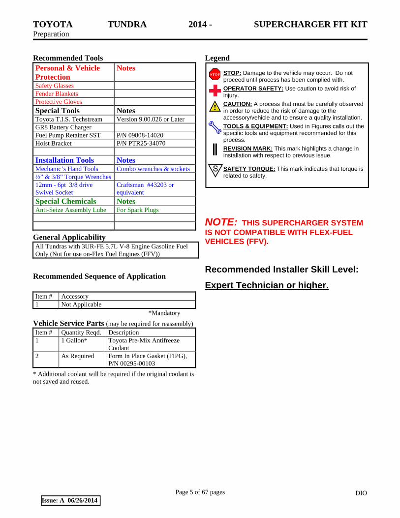
Recommended Tools Personal & Vehicle Protection
Notes
Safety Glasses Fender Blankets Protective Gloves
Special Tools Notes Toyota T.I.S. Techstream Version 9.00.026 or Later GR8 Battery Charger Fuel Pump Retainer SST P/N 09808-14020 Hoist Bracket P/N PTR25-34070
Installation Tools Notes Mechanic’s Hand Tools Combo wrenches & sockets ½” & 3/8” Torque Wrenches 12mm - 6pt 3/8 drive Swivel Socket
Craftsman #43203 or equivalent
Special Chemicals Notes Anti-Seize Assembly Lube For Spark Plugs
General Applicability All Tundras with 3UR-FE 5.7L V-8 Engine Gasoline Fuel Only (Not for use on-Flex Fuel Engines (FFV))
Recommended Sequence of Application
Item # Accessory 1 Not Applicable
*Mandatory
Vehicle Service Parts (may be required for reassembly) Item # Quantity Reqd. Description 1 1 Gallon* Toyota Pre-Mix Antifreeze
Coolant 2 As Required Form In Place Gasket (FIPG),
P/N 00295-00103
* Additional coolant will be required if the original coolant is not saved and reused.
Legend
NOTE: THIS SUPERCHARGER SYSTEM IS NOT COMPATIBLE WITH FLEX-FUEL VEHICLES (FFV). Recommended Installer Skill Level:
Expert Technician or higher.
STOP: Damage to the vehicle may occur. Do not proceed until process has been complied with.
OPERATOR SAFETY: Use caution to avoid risk of injury.
CAUTION: A process that must be carefully observed in order to reduce the risk of damage to the accessory/vehicle and to ensure a quality installation.
TOOLS & EQUIPMENT: Used in Figures calls out the specific tools and equipment recommended for this process.
REVISION MARK: This mark highlights a change in installation with respect to previous issue. SAFETY TORQUE: This mark indicates that torque is related to safety.

TOYOTA TUNDRA 2014 - SUPERCHARGER FIT KIT Procedure
Page 6 of 67 pages DIOIssue: A 06/26/2014
Care must be taken when installing this accessory to ensure damage does not occur to the vehicle. The installation of this accessory should follow approved guidelines to ensure a quality installation. These guidelines can be found in the "Accessory Installation Practices" document. This document covers such items as:-
Vehicle Protection (use of covers and blankets, cleaning chemicals, etc.). Safety (eye protection, rechecking torque procedure, etc.). Vehicle Disassembly/Reassembly (panel removal, part storage, etc.). Electrical Component Disassembly/Reassembly (battery disconnection, connector removal, etc.).
Please see your Toyota dealer for a copy of this document.
1. Installation Review and Vehicle Preparation.
(a) Review the entire instruction instructions
provided before beginning the installation.
(b) Review the parts list/kit contents to ensure
that all parts are present before beginning the
installation. If any items are missing contact
Technical Support at (800) 688-5912 before
proceeding.
(c) Remove any low-octane fuel from the
vehicle. Ensure that ONLY 91 octane or
higher unleaded gasoline is used.
(d) Place the vehicle onto a vehicle hoist.
(e) Protect the vehicle with protection blankets
over the fenders and front of the vehicle.
(f) Disconnect and remove the battery.
(g) When draining the cooling system into a
clean container in Step 3, save this coolant as
it will be reused.
CAUTION: To avoid the danger of being
burned, do not remove the radiator cap while
the engine and radiator are still hot. Thermal
expansion will cause the hot engine coolant
and steam to blow out from the radiator.
(h) All parts that are removed and not reused
should be saved for the customer, i.e.,
“discard” means to save for the customer.

TOYOTA TUNDRA 2014 - SUPERCHARGER FIT KIT Procedure
Page 7 of 67 pages DIOIssue: A 06/26/2014
Fig. 2-1
Fig. 2-2
Fig. 3-1
2. Remove the engine cover.
(a) Remove the engine V-bank cover by lifting
the front of the cover and pulling away from
the firewall (Fig. 2-1). Discard these parts.
(b) If installed, remove the No. 1 engine under
cover (Fig. 2-2) by removing the 3 screws
and 5 bolts. Save these parts for reuse.
3. Drain the Engine Coolant.
CAUTION: Do not remove the radiator cap
while the engine and radiator are still hot.
Pressurized hot engine coolant and steam may
be released and cause serious burns.
(a) Loosen the radiator drain cock plug
(Fig. 3-1).
(b) Remove the radiator cap. Drain the coolant
from the radiator into a clean container so it
can be reused (Fig. 3-1).
(c) Loosen the 2 cylinder block drain cock plugs
(Fig. 3-1). Drain the coolant from the engine
and save it for reuse.
(d) Tighten the 2 cylinder block drain cock
plugs.
Torque: 13 N-m (10 ft-lbf)

TOYOTA TUNDRA 2014 - SUPERCHARGER FIT KIT Procedure
Page 8 of 67 pages DIOIssue: A 06/26/2014
Fig. 4-1
Fig. 5-1
Fig. 5-2
4. Remove the Hood Sub-Assembly.
(a) Use a screwdriver to release the 2 clips and
remove the hood support assembly (Fig. 4-1).
HINT: Tape the screwdriver tip before use.
CAUTION: Remove the hood support assembly
while supporting the hood by hand.
(b) Remove the 4 bolts and the hood.
5. Remove the Wiper Motor & Link Assembly.
(a) Use a clip remover to detach the 16 claws
and remove the cowl top seal (Fig. 5-1).
(b) Use a clip remover to detach the claw and
remove the cowl LH side seal. Repeat for the
RH side.
(c) Remove 2 clips and 8 claws and remove the
top ventilator louver sub-assembly (Fig. 5-2).

TOYOTA TUNDRA 2014 - SUPERCHARGER FIT KIT Procedure
Page 9 of 67 pages DIOIssue: A 06/26/2014
Fig. 5-3
Fig. 6-1
Fig. 7-1
(d) Disconnect the electrical connector, 1 nut and
4 bolts, and then remove the wiper motor and
link assembly (Fig. 5-3).
6. Remove the Cowl Top Outer Panel Sub-Assembly.
(a) Disconnect the washer hose and detach the 2
wire harness clamps (Fig. 6-1).
(b) Remove the 2 bolts and the cowl top outer
sub-assembly (Fig. 6-1).
7. Remove the Radiator Grill Sub-Assembly.
(a) Put protective tape around the radiator grill
sub-assembly (Fig. 7-1).
(b) Remove the 4 screws and 2 clips (Fig. 7-1).

TOYOTA TUNDRA 2014 - SUPERCHARGER FIT KIT Procedure
Page 10 of 67 pages DIOIssue: A 06/26/2014
Fig. 7-2
Fig. 8-1
Fig. 9-1
(c) Detach the 4 claws and 3 clips and remove
the radiator sub-assembly (Fig. 7-2).
8. Remove the Front LH End Panel.
(a) Put protective tape around the LH front end
panel (Fig. 8-1).
(b) Remove the 2 screw and 2 clips (Fig. 8-1).
(c) Detach the 3 claws and remove the front LH
end panel (Fig. 8-1).
9. Modify the LH Radiator Side Deflector.
(a) Use a clip remover to remove the 3 clips and
disconnect the radiator side deflector LH
(Fig. 9-1).

TOYOTA TUNDRA 2014 - SUPERCHARGER FIT KIT Procedure
Page 11 of 67 pages DIOIssue: A 06/26/2014
Fig. 9-2
Top Bottom
Fig. 10-1
Fig. 10-2
(b) Mark and trim the LH radiator side deflector
(Fig. 9-2).
(c) Reinstall the LH radiator side deflector.
10. Remove the Fan and Shroud.
(a) Remove the upper radiator hose.
(1) Mark the radiator end of this hose with a
marker or tape.
(2) This hose will be reinstalled inverted and
the mark will help identify the ends.
(b) Loosen the 4 nuts holding the fluid coupling
fan (Fig. 10-1).
(c) Remove the fan/generator V-rib belt. Discard
this belt as it will be replaced by a new belt.
(d) Disconnect the reservoir hose from the upper
radiator tank.
(e) For vehicles with a condenser with an
integrated oil cooler: Detach the claw to open
the No. 1 hose clamp on the side of the fan
shroud (Fig. 10-2).

TOYOTA TUNDRA 2014 - SUPERCHARGER FIT KIT Procedure
Page 12 of 67 pages DIOIssue: A 06/26/2014
Fig. 10-3
Fig. 11-1
Fig. 11-2
(f) Remove the 2 bolts retaining the fan shroud
(Fig. 10-3).
(g) Remove the 4 nuts of the fluid coupling fan,
and then remove the shroud together with the
coupling fan. Retain these parts for reuse.
(h) Temporarily re-install the 4 nuts to keep the
pulley in place (reference Fig. 10-1). Do not
tighten.
CAUTION: Be careful not to damage the
radiator core. It is helpful to protect the
radiator core with a piece of cardboard to
prevent damage during the following steps.
11. Replace the Air Cleaner Upper Lid, Filter and Inlet.
(a) Remove the air cleaner hose.
(1) Disconnect the vacuum and ventilation
hoses and loosen the 2 clamps (Fig. 11-
1).
(2) Discard the hose and clamps.
(b) Remove the air cleaner lid.
(1) Disconnect the mass airflow (MAF)
meter connector (Fig. 11-2).
(2) Use a clip removal tool to detach the wire
harness clamp.
(3) Unfasten the 4 hook clamps (Fig. 11-2).
(c) Remove and discard the air cleaner element.

TOYOTA TUNDRA 2014 - SUPERCHARGER FIT KIT Procedure
Page 13 of 67 pages DIOIssue: A 06/26/2014
Fig. 11-3
Fig. 11-4
Fig. 11-5
Fig. 11-6
(d) Remove the mass airflow (MAF) meter from
the air cleaner lid (Fig. 11-3). Discard the air
cleaner lid but retain the 2 screws.
(e) Install the mass airflow (MAF) meter in the
supplied air cleaner lid (Item #3) using the
OE screws (Fig. 11-3).
Torque: 1.7 N-m (15 in-lbf)
(f) Remove the air cleaner case by removing the
2 bolts (Fig. 11-4).
(g) Use a flat blade screwdriver to unclip and
discard the air inlet tube from the air cleaner
case (Fig. 11-5).
(h) Install the new air flow accelerator (Item E6)
into the opening in the inner fender panel
(Fig. 11-6).
HINT: Squeeze and compress the bell mouth of
the air flow accelerator in order to get it through
the opening in the inner fender.

TOYOTA TUNDRA 2014 - SUPERCHARGER FIT KIT Procedure
Page 14 of 67 pages DIOIssue: A 06/26/2014
Fig. 12-1
Fig. 12-2 Do Not Remove
Remove
Remove
No. 4 Hose
(i) Reinstall the air cleaner case using the
original bolts.
(1) The inlet to the case is inserted into and
snaps to the air flow accelerator.
(2) Once the two parts are snapped together,
push the air flow accelerator further
through the panel so the bolt holes line
up.
Torque: 5.0 N-m (44 in-lbf)
12. Remove the Intake Manifold.
(a) Blow away dirt and debris that has
accumulated around the intake manifold
ports and the fuel injectors.
CAUTION: Wear eye protection when using
compressed air.
(b) Disconnect the ventilation hose from the
ventilation pipe on the cylinder head covers,
LH and RH (Fig. 12-1).
(c) Disconnect the No. 4 water bypass hose and
the throttle body connector (Fig. 12-2). Do
not disconnect the No. 5 water bypass hose
from the water inlet housing or the throttle
body.
TOYOTA TUNDRA 2014 - SUPERCHARGER FIT KIT Procedure
Page 15 of 67 pages DIOIssue: A 06/26/2014
Fig. 12-4
Fig. 12-5
Fig. 12-6
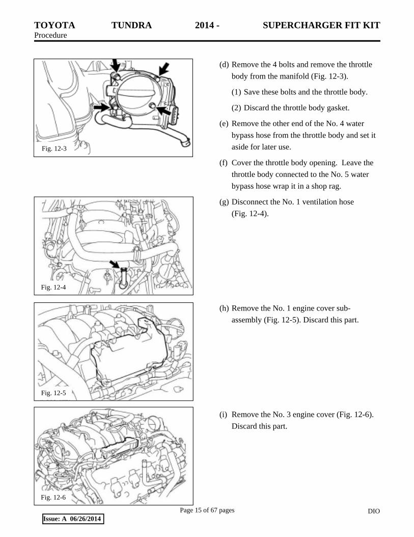
(d) Remove the 4 bolts and remove the throttle
body from the manifold (Fig. 12-3).
(1) Save these bolts and the throttle body.
(2) Discard the throttle body gasket.
(e) Remove the other end of the No. 4 water
bypass hose from the throttle body and set it
aside for later use.
(f) Cover the throttle body opening. Leave the
throttle body connected to the No. 5 water
bypass hose wrap it in a shop rag.
(g) Disconnect the No. 1 ventilation hose
(Fig. 12-4).
(h) Remove the No. 1 engine cover sub-
assembly (Fig. 12-5). Discard this part.
(i) Remove the No. 3 engine cover (Fig. 12-6).
Discard this part.
Fig. 12-3

TOYOTA TUNDRA 2014 - SUPERCHARGER FIT KIT Procedure
Page 16 of 67 pages DIOIssue: A 06/26/2014
Fig. 12-7
Fig. 12-8
Fig. 12-9
(j) Disconnect the purge VSV connector, the
hose from the VSV, and the ACIS connector
(Fig. 12-7).
(1) Disconnect the purge line hose from the
body of the purge valve.
(2) Disconnect the purge hose from the front
of the intake manifold, but leave it
connected to the front of the purge valve.
(3) Unbolt the purge valve and set it and the
bolt aside for now.
(k) Remove the brake booster vacuum hose from
the manifold pipe and the brake booster (Fig.
12-8). Save the clamps, but discard the hose.
(l) Disconnect the 3 wire clamps from the 3 wire
harness brackets (Fig. 12-9).

TOYOTA TUNDRA 2014 - SUPERCHARGER FIT KIT Procedure
Page 17 of 67 pages DIOIssue: A 06/26/2014
Fig. 12-10
Fig. 12-11
Fig. 12-13
(m) Use a 12mm 6 point 3/8” drive swivel socket
to remove the 2 nuts, 8 bolts and the intake
manifold (Fig. 12-10).
(n) Remove the 2 harness clips from the back of
the intake manifold. These will be reused in
Step 18(b) (Fig. 12-11).
(o) Clean and cover the intake ports to prevent
debris from entering the engine and then
remove and discard the 2 foam engine covers
that are under the intake manifold (Fig. 12-
12). Blow away any debris that may be in the
engine valley.
(p) Remove the 2 bolts and the ventilation hose
from the intake manifold (Fig. 12-13). Set
the hose aside for later reuse.
Fig. 12-12
Cover Intake Ports
Foam Engine Covers

TOYOTA TUNDRA 2014 - SUPERCHARGER FIT KIT Procedure
Page 18 of 67 pages DIOIssue: A 06/26/2014
Fig. 12-14
Fig. 13-1
Fig. 13-2
No. 9
No. 10
(q) Carefully remove the gaskets from the
bottom of the intake manifold (Fig. 12-14).
(1) Clean and set them aside as they will be
reused in Step 18(a).
(2) Discard the intake manifold and the
remaining attached parts.
CAUTION: Be careful not to damage the
gaskets. If the gaskets appear to be worn or
damaged, replace them with new ones (Qty 2:
Toyota P/N 17171-38010 or 17171-0S010 or
equivalent superseded part).
13. Remove the Coolant Crossover Manifold.
(a) Unplug the water temperature sensor, remove
it and set it aside (Fig. 13-1).
CAUTION: Do not misplace the copper sealing
washer.
(b) Remove the No. 9 and No. 10 hoses from the
coolant crossover manifold (Fig. 13-2).

TOYOTA TUNDRA 2014 - SUPERCHARGER FIT KIT Procedure
Page 19 of 67 pages DIOIssue: A 06/26/2014
Fig. 13-4
Fig. 13-5
(c) Remove the No. 1 hose and discard it (Fig.
13-3).
(d) Disconnect the No. 2 water bypass hose from
the coolant crossover manifold (Fig. 13-3).
(e) Remove the 3 bolts and 4 hoses and then
remove the No. 2 water bypass pipe
assembly (Fig. 13-4).
HINT: When the lower hoses are disconnected,
they will be full of coolant. Drain this coolant
into a clean container for reuse.
(f) Remove and save the hoses from the hard
bypass pipe assembly. Discard the No. 2 hard
bypass pipe assembly.
(g) Remove the 4 nuts, front coolant crossover
manifold and 2 gaskets (Fig. 13-5).
(1) Retain the nuts and gaskets.
(2) Discard the coolant crossover manifold.
(3) Clean the gaskets and mating surfaces on
the engine.
14. Install the Coolant Crossover Manifold.
(a) Carefully inspect the gaskets removed from
the coolant crossover manifold. If the
gaskets are worn or aged in any way, replace
them with new gaskets: Toyota P/N 16341-
38030 (QTY 2) or an equivalent superseded
part.
NOTE: No FIPG is required or recommended
on new gaskets.
Fig. 13-3 No. 1
No. 2

TOYOTA TUNDRA 2014 - SUPERCHARGER FIT KIT Procedure
Page 20 of 67 pages DIOIssue: A 06/26/2014
(b) If the coolant crossover manifold gaskets are
to be re-used, apply a very LIGHT coat of
Toyota FIPG (Form in Place Gasket) to both
sides of the gaskets and place them over the
studs on the engine.
NOTE: Excess FIPG may cause future cooling
system problems.
(c) Slide the new supplied coolant crossover
manifold (Item #4) over the studs and secure
it with the previously removed 4 nuts (Fig.
14-1).
Torque: 21N-m (15ft-lbf)
(d) Install the water temperature sensor (Fig. 14-
1).
Torque: 20N-m (14ft-lbf)
(e) Reconnect the wire harness.
15. Install the Idler Pulley.
(a) Remove the 2 M10 bolts and the M8 bolt
from the engine timing chain cover and fan
bracket (Fig. 15-1). Discard these 3 bolts.
Fig. 15-1
Fig. 14-1
4X
Water temp. sensor
TOYOTA TUNDRA 2014 - SUPERCHARGER FIT KIT Procedure
Page 21 of 67 pages DIOIssue: A 06/26/2014
Fig. 15-4
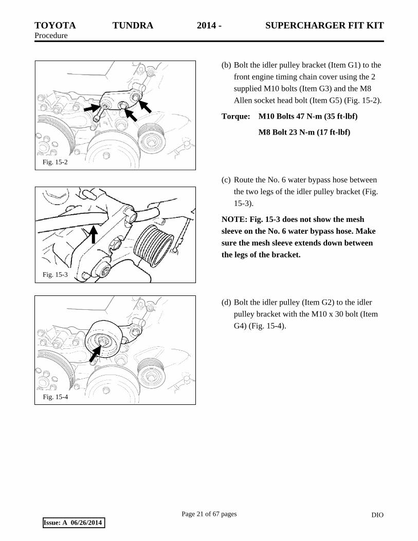
(b) Bolt the idler pulley bracket (Item G1) to the
front engine timing chain cover using the 2
supplied M10 bolts (Item G3) and the M8
Allen socket head bolt (Item G5) (Fig. 15-2).
Torque: M10 Bolts 47 N-m (35 ft-lbf)
M8 Bolt 23 N-m (17 ft-lbf)
(c) Route the No. 6 water bypass hose between
the two legs of the idler pulley bracket (Fig.
15-3).
NOTE: Fig. 15-3 does not show the mesh
sleeve on the No. 6 water bypass hose. Make
sure the mesh sleeve extends down between
the legs of the bracket.
(d) Bolt the idler pulley (Item G2) to the idler
pulley bracket with the M10 x 30 bolt (Item
G4) (Fig. 15-4).
Fig. 15-2
Fig. 15-3

TOYOTA TUNDRA 2014 - SUPERCHARGER FIT KIT Procedure
Page 22 of 67 pages DIOIssue: A 06/26/2014
Fig. 16-1
Fig. 16-2
Fig. 16-3
16. Install the Water Hoses.
(a) Reconnect the No. 2 water bypass hose to the
water bypass joint using the original clamp
(Fig. 14-1 & Fig. 16-1).
(b) Unclip the wire harness from the stud on the
front of the timing cover on the driver side of
the engine (Fig. 16-2).
(c) Use an E-6 Torx socket to remove the stud
and discard it (Fig. 16-2).
(d) Use a 3 mm Allen socket to install the M6 x
30 mm Allen stud (Item C4) (Fig. 16-2).
(e) Attach the hoses removed in Step 13(f) to the
oil cooler hard coolant lines (Item C1) using
the OE clamps (Fig. 13-4 & Fig. 16-3).
(f) Mount the oil cooler hard coolant lines (Item
C1) to the M6 x 30 mm Allen stud using the
supplied M6 nut (Item C5) (Fig. 16-3).
Leave the nut finger tight for now.
NOTE: For clarity, some parts normally on
the engine are not shown.
TOYOTA TUNDRA 2014 - SUPERCHARGER FIT KIT Procedure
Page 23 of 67 pages DIOIssue: A 06/26/2014
Fig. 16-4
Fig. 16-5
Fig. 16-6
3” 2 ¾”
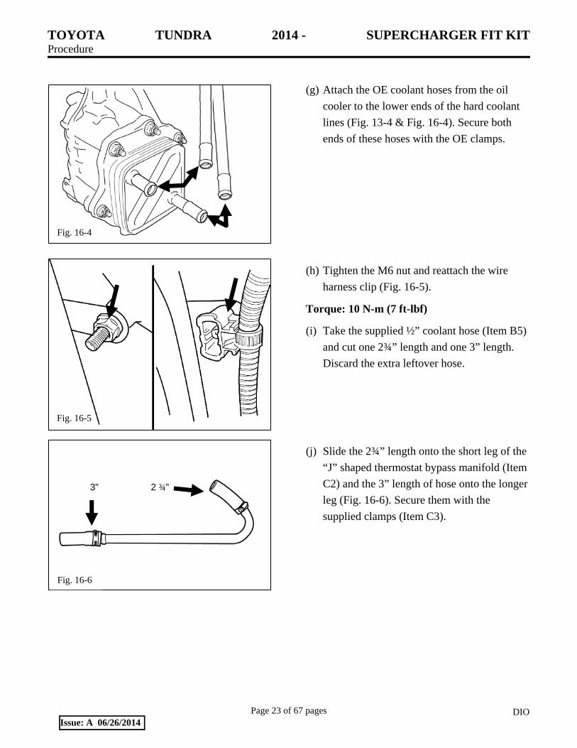
(g) Attach the OE coolant hoses from the oil
cooler to the lower ends of the hard coolant
lines (Fig. 13-4 & Fig. 16-4). Secure both
ends of these hoses with the OE clamps.
(h) Tighten the M6 nut and reattach the wire
harness clip (Fig. 16-5).
Torque: 10 N-m (7 ft-lbf)
(i) Take the supplied ½” coolant hose (Item B5)
and cut one 2¾” length and one 3” length.
Discard the extra leftover hose.
(j) Slide the 2¾” length onto the short leg of the
“J” shaped thermostat bypass manifold (Item
C2) and the 3” length of hose onto the longer
leg (Fig. 16-6). Secure them with the
supplied clamps (Item C3).

TOYOTA TUNDRA 2014 - SUPERCHARGER FIT KIT Procedure
Page 24 of 67 pages DIOIssue: A 06/26/2014
Fig. 16-7
Fig. 16-8
Fig. 16-9
No. 4 Hose
Fig. 16-10
(k) Slide a supplied screw clamp (Item C3) on
each end of the “J” shaped bypass manifold
(Item C2) and attach it to the thermostat
housing and the coolant crossover manifold
(Fig. 16-7). Ensure the tube fits comfortably
without any kinks and tighten the screw
clamps.
(l) Make certain the hose clamps on the water
bypass hoses No. 9 & No. 10 are oriented as
shown in Fig. 16-8.
(m) Install the No. 4 water bypass hose (Fig. 16-
9). This hose was removed in Step 12(c).
(n) Remove and save the OE clamp and then
trim the free end of the hose (Fig. 16-10).

TOYOTA TUNDRA 2014 - SUPERCHARGER FIT KIT Procedure
Page 25 of 67 pages DIOIssue: A 06/26/2014
Fig. 16-11
Fig. 16-12
Fig. 17-1
(o) Use a 5/16” hose mender (Item A19) and the
OE clamps to connect hose No. 4 & No. 9
(Fig. 16-11).
(p) Cut the 30” long mesh sleeve (Item B10) into
three pieces: one 14” long and two 8” long.
(q) Slide the 14” piece of mesh sleeve over the
5/16” heater hose, Item B6.
(r) Use the remaining 5/16” hose mender (Item
A19) and clamp (Item A20) to connect one
end of the heater hose to the free end of hose
No. 10 (Fig. 16-12). Leave the other end of
the heater hose free for now.
(s) Orient the hose clamps as shown and then
secure the two hose assemblies with 2 tie
wraps (Item A15) (Fig. 16-12).
17. Remove the Fuel Injectors.
CAUTION: The fuel system is under high
pressure. Use safety glasses and fuel-
compatible gloves to prevent personal injury.
(a) Unplug the No. 6 and No. 7 wire harness
connectors from the RH and LH fuel rail
harnesses (Fig. 17-1).

TOYOTA TUNDRA 2014 - SUPERCHARGER FIT KIT Procedure
Page 26 of 67 pages DIOIssue: A 06/26/2014
Fig. 17-2
Fig. 17-3
(b) Disconnect the No. 2 fuel tube from the fuel
pressure regulator (Fig. 17-2). Place shop
rags around the fitting to prevent fuel spray
and to absorb any fuel that comes out of the
line.
(c) Disconnect the No.1 fuel tube from the back
of each fuel delivery pipe sub-assembly (Fig.
17-2).
(d) Disconnect the fuel tube sub-assembly from
the front of the LH fuel delivery pipe sub-
assembly (Fig. 17-2). Use shop rags to
absorb any fuel as each connector is
disconnected.
(e) Unbolt and remove the fuel delivery pipe
sub-assemblies. Retain the four bolts (Fig.
17-3).
CAUTION: The fuel delivery pipe sub-
assemblies have fuel in them which must be
drained into an approved disposal container.
NOTICE: When removing the delivery pipes,
hold the pipes by the ends and pull them
straight upwards.
(f) Remove and retain the four spacers.
(g) Remove the eight insulators from either the
intake manifold or from the injectors.
(1) Clean the insulators and inspect them for
damage and wear.
(2) If any damage or wear is evident, replace
all 8 insulators with new parts (Toyota
P/N 23291-23010 or equivalent
superseded part).
(h) Install the insulators into the cylinder heads.

TOYOTA TUNDRA 2014 - SUPERCHARGER FIT KIT Procedure
Page 27 of 67 pages DIOIssue: A 06/26/2014
Fig. 17-4
Lubricate gasket with oil
Fig. 18-1
Fig. 18-2
(i) Remove the fuel injectors from the fuel
delivery pipes (Fig. 17-4).
(1) As each injector is removed, disconnect
the injector connector (Fig. 17-4).
(2) Discard the injectors.
(j) Cover all eight injector ports in the cylinder
heads and all open fuel lines to prevent
debris contamination.
18. Prepare to Install the Supercharger.
(a) Coat the intake manifold gaskets removed in
Step 12(q) with a light film of oil and install
them on the bottom of the supercharger (Fig.
18-1).
(b) Install the wire harness clips removed in Step
12(n) onto the cast bosses on the back of the
supercharger (Fig. 18-2).
Torque: 10 N-m (7 ft-lbf)

TOYOTA TUNDRA 2014 - SUPERCHARGER FIT KIT Procedure
Page 28 of 67 pages DIOIssue: A 06/26/2014
Fig. 18-3
Fig. 18-4
Fig. 19-1
Fig. 19-2
(c) Attach the TRD hoist bracket to the top of
the supercharger with the M8 bolts that are
part of the hoist bracket kit (Fig. 18-3).
Torque: 21 N-m (15 ft-lbf)
NOTE: This bracket is not part of the kit and
needs to be ordered separately, P/N PTR25-
34070.
(d) On the rear RH corner of the supercharger is
a M6 Allen head threaded stud that is only
used on 2013 MY and earlier Tundras.
Remove and discard this stud (Fig. 18-4).
19. Install the Supercharger Housing.
(a) Install the new vent hose (Item C6) with the
supplied clamp (Item C7) (Fig. 19-1).
(b) Use an engine hoist to lift the supercharger
by hooking the hoist to the hoist bracket
bolted to the top of the supercharger (Fig. 19-
2).
(c) Remove the tape covering the intake ports in
the cylinder heads (refer to Fig. 12-12). Make
sure the surface is clean.
TOYOTA TUNDRA 2014 - SUPERCHARGER FIT KIT Procedure
Page 29 of 67 pages DIOIssue: A 06/26/2014
Fig. 20-1
New Original
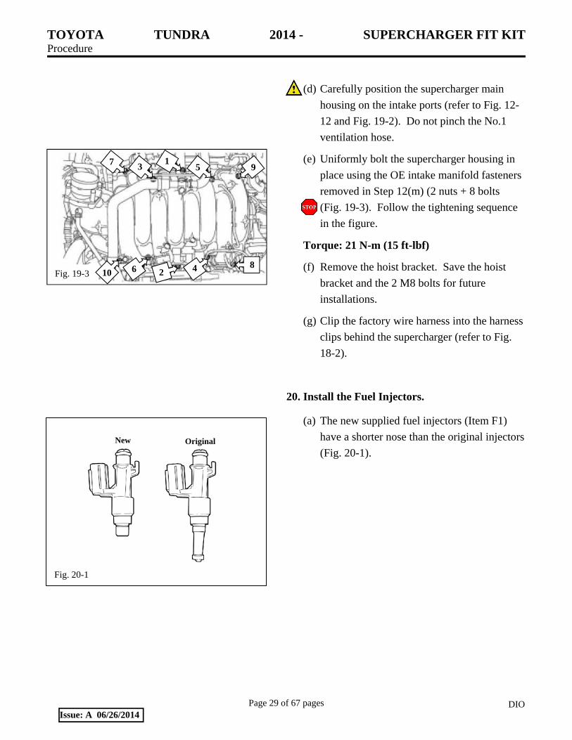
(d) Carefully position the supercharger main
housing on the intake ports (refer to Fig. 12-
12 and Fig. 19-2). Do not pinch the No.1
ventilation hose.
(e) Uniformly bolt the supercharger housing in
place using the OE intake manifold fasteners
removed in Step 12(m) (2 nuts + 8 bolts
(Fig. 19-3). Follow the tightening sequence
in the figure.
Torque: 21 N-m (15 ft-lbf)
(f) Remove the hoist bracket. Save the hoist
bracket and the 2 M8 bolts for future
installations.
(g) Clip the factory wire harness into the harness
clips behind the supercharger (refer to Fig.
18-2).
20. Install the Fuel Injectors.
(a) The new supplied fuel injectors (Item F1)
have a shorter nose than the original injectors
(Fig. 20-1).
Fig. 19-3
7 3 1
5 9
8 4 2 6 10

TOYOTA TUNDRA 2014 - SUPERCHARGER FIT KIT Procedure
Page 30 of 67 pages DIOIssue: A 06/26/2014
Fig. 20-3
Fig. 20-4
(b) Connect the injector connector (Fig. 20-2).
(c) Apply a light coat of gasoline or spindle oil
onto the upper injector O-ring and install the
injector to the fuel delivery pipe (Fig. 20-2).
NOTICE:
Make sure that no scratches or foreign
matter exist in or around the insertion
hole of the delivery pipe.
When inserting the injector, be careful
not to damage the O-ring.
Attach the part of the injector labeled
B between the parts of the delivery
pipe labeled A.
(d) Check to see that each injector is installed to
the delivery pipe facing the direction shown
(Fig. 20-3).
(e) Apply a light coat of oil to the ID of the
insulators in the cylinder heads.
(f) Install the 2 delivery pipe spacers and make
sure the 4 insulators are in place in each
cylinder head.
(g) Install the 2 delivery pipes (with injectors) to
the cylinder heads.
(h) Install the 2 bolts on each side (Fig. 20-4).
Torque: 21 N-m (15 ft-lbf)
Fig. 20-2
O-Ring
Connector

TOYOTA TUNDRA 2014 - SUPERCHARGER FIT KIT Procedure
Page 31 of 67 pages DIOIssue: A 06/26/2014
Fig. 20-5
Fig. 21-2
Fig. 21-3
OE Purge Valve Bracket
Reservoir Bracket A9
OE Screw
Fig. 21-1
Forward Rear
Middle
(i) Reconnect the No. 6 and No. 7 wire harness
connectors (Fig. 20-5).
(j) Connect the 4 fuel line connectors, 2 per side
(Fig. 20-5).
21. Install the Vacuum Hoses.
(a) The supercharger housing has three barbs at
the front (Fig. 21-1). These will be referred
to in subsequent steps as the “forward,”
“middle,” and “rear” barbs.
(b) Attach the No. 1 ventilation hose to the
forward barb (Fig. 21-1 & Fig. 21-2) using
the OE clamp.
(c) Remove the purge valve (VSV) from the OE
bracket and mount it onto the reservoir
bracket (Item A9) using the OE screw (Fig.
21-3).

TOYOTA TUNDRA 2014 - SUPERCHARGER FIT KIT Procedure
Page 32 of 67 pages DIOIssue: A 06/26/2014
Fig. 21-4
Fig. 21-5
Seal ACIS Connector with
Tape
Purge Hose No. 1
Purge Hose No. 2
(d) Mount the reservoir bracket (Item A9) to the
driver’s side of the supercharger using the
supplied button head screws (Item A12),
8mm hex head bolt (Item A10) and 6mm hex
head bolt (Item A11) (Fig. 21-4).
NOTE: For clarity, the VSV is not shown in
the figure.
Torque: M8 Bolt 20N-m (15 ft-lbf)
M6 Bolt 10 N-m (84 in-lbf)
(e) Connect the electrical connector to the purge
valve.
(1) The valve has 2 connectors and only 1
will fit.
(2) The ACIS connector is no longer used
and should be sealed with electrical tape
and secured to the main harness (Fig. 21-
5).
(f) Reconnect purge hose No. 1to the body of
the purge valve with the OE clamp (Fig. 21-
5).

TOYOTA TUNDRA 2014 - SUPERCHARGER FIT KIT Procedure
Page 33 of 67 pages DIOIssue: A 06/26/2014
Fig. 21-6
Fig. 21-7
Fig. 21-8
Fig. 21-9
B4
A17
(g) Before purge hose No. 2 can be attached to
the rear barb, it needs to be shortened
approximately 3” (Fig. 21-6 & Fig. 21-7).
HINT: Mark and check the length before
cutting the hose.
(h) Take one of the two 8” long mesh sleeves cut
in Step 16(p) and slide it on purge hose No.
2, taping the ends in place with electrical tape
(Fig. 21-7).
(1) The mesh should start 1” from the end of
the hose.
(2) Attach the hose to the rear barb (Fig. 21-
7).
(i) Slide the remaining 8” piece of mesh sleeve
onto the 11/32” x 26” hose (Item B4), taping
the ends in place with electrical tape (Fig. 21-
8).
(1) The mesh should start 1” from the end of
the hose.
(2) Connect the brake booster to the center
barb using the previously removed OE
clamps from Step 12(k).
(j) Connect the brake vacuum hose (Item B4) to
the AC hard line with the swivel hose clip
(Item A17) (Fig. 21-9).

TOYOTA TUNDRA 2014 - SUPERCHARGER FIT KIT Procedure
Page 34 of 67 pages DIOIssue: A 06/26/2014
Fig. 21-10
Fig. 22-1
Fig. 22-3
Fig. 22-2
Connector toward rear of the vehicle
(k) Mount the reservoir (Item D2) to the
reservoir bracket (Item A9) using the 3 bolts
that came preinstalled in the reservoir (Fig.
21-10).
Torque: 10 N-m (84 in-lbf)
22. Install the Throttle Body.
(a) Install the supplied throttle body O-ring
(Item J2) in the groove on the nose of the
supercharger housing (Fig. 22-1).
(b) Rotate the throttle body 180° from the OE
position so that the connector is toward the
rear of the vehicle.
(c) Fasten the throttle body to the supercharger
housing with the 4 OE bolts (Fig. 22-2).
Torque: 21 N-m (15 ft-lbf)
(d) Unclip the 3 wire harness clips (Fig. 22-3).
(e) Remove the 3 clips from the wire harness
using a small flat blade screwdriver to release
the lock tabs.

TOYOTA TUNDRA 2014 - SUPERCHARGER FIT KIT Procedure
Page 35 of 67 pages DIOIssue: A 06/26/2014
Fig. 22-5
Fig. 22-6
(f) Unplug the 2 VVT sensors and the front air
injection connector (Fig. 22-4).
(g) Open the wire harness and remove the wire
loom wrap up to the junction where the wire
loom that contains the throttle and air
injection wires branch out from the main
harness (Fig. 22-5).
(h) Separate the throttle motor wires from the air
injection wires (Fig. 22-5).
(i) Install a 9” length of the supplied 3/8”
convoluted tube (Item B7) over the exposed
throttle motor wires and secure it with
electrical tape (Fig. 22-6).
(j) Reinstall the original wire loom wrap over
the air injection wires and secure it with
electrical tape (Fig. 22-6).
(k) Tape the rest of the harness closed.
(l) Attach the 3 clamps back onto the harness
and clip them to their mounting brackets.
Fig. 22-4

TOYOTA TUNDRA 2014 - SUPERCHARGER FIT KIT Procedure
Page 36 of 67 pages DIOIssue: A 06/26/2014
Fig. 22-8
Fig. 23-1
IP
IP
AC
Fan WP
PS
ALT
Fig. 23-2
(m) Plug in the throttle body connector, the air
injection connector, and the 2 VVT sensors
(Fig. 22-7).
(n) Install the free end of the 5/16” heater hose
onto the front facing barb of the throttle
body. Secure it using the remaining spring
clamp (Item A20) (Fig. 16-12 & Fig. 22-8).
23. Install the Belt, Fan & Fan Shroud, and the Radiator Hose.
(a) Install the supplied drive belt (Item #9)
following the outlined belt routing (Fig. 23-
1). Ensure the belt is completely on all of the
pulleys.
(b) Remove anything covering the radiator used
for core damage prevention.
(c) Remove the 4 nuts temporarily holding the
fan pulley in place.
(d) Lower the fan and shroud together. Clip the
fan shroud into the lower radiator mounting
tabs (Fig. 23-2).
Fig. 22-7

TOYOTA TUNDRA 2014 - SUPERCHARGER FIT KIT Procedure
Page 37 of 67 pages DIOIssue: A 06/26/2014
Fig. 23-3
Fig. 24-1
(e) Bolt the fan clutch to the fan pulley using the
4 OE nuts (Fig. 23-3).
Torque: 21 N-m (15 ft-lbf)
(f) Install the fan shroud using the 2 OE bolts
(Fig. 23-2).
Torque: 6.5 Nm (58 in-lbf)
(g) Install the upper radiator hose.
(1) The radiator side of this hose should have
been marked during removal in Step
10(a)(1).
(2) The marked side will now attach to the
coolant crossover manifold and the other
(unmarked) side to the radiator.
(3) Secure it using the OE spring clamps.
(h) Connect the coolant overflow hose to the
upper radiator tank.
24. Replace the Spark Plugs.
(a) Unplug and remove all 8 coils (Fig. 24-1).
(b) Blow out any debris from the spark plug
holes. Wear eye protection.
(c) Remove and discard all 8 spark plugs.
(d) Apply a small amount of anti-seize to the
threads of the new supplied spark plugs (Item
F2).
(e) Install all 8 spark plugs (Plug Gap: 0.032”).
Torque: 18 N-m (13 ft-lbf)
(f) Reinstall all 8 coils.
Torque: 9 N-m (80 in-lbf)
(g) Reconnect the 8 coil connectors.

TOYOTA TUNDRA 2014 - SUPERCHARGER FIT KIT Procedure
Page 38 of 67 pages DIOIssue: A 06/26/2014
Fig. 25-3
25. Install the Vent Hoses.
(a) The ventilation hose assembly is shown as
removed from the intake manifold (Fig. 25-
1).
(1) Remove the long hose from the “T”, flip
it end for end, and reconnect it to the “T”
(Fig. 25-2).
(2) Remove the clamp from the long hose,
rotate it, and then reinstall it so it points
toward the front of the engine (Fig. 25-2).
(b) Mount the ventilation hose assembly to the
supercharger with the OE bolts
(1) The M6 bolt attaches the “T” to the RH
side of the supercharger housing (Fig. 25-
3).
Torque: 10 N-m (84 in-lbf)
(2) The M8 bolt attaches the clamp on the
long hose to the front of the supercharger
housing (Fig. 25-3).
Torque: 21 N-m (15 ft-lbf)
(c) Connect the loose end of the long hose to the
LH cam cover (Fig. 25-3).
Fig. 25-1
Middle hose
“T”
Long hose original configuration
Fig. 25-2
Long hose flipped end-for-end

TOYOTA TUNDRA 2014 - SUPERCHARGER FIT KIT Procedure
Page 39 of 67 pages DIOIssue: A 06/26/2014
Fig. 25-4
1” 2”
Fig. 25-5
(d) Remove the middle hose from the “T” and
trim it so that it will neatly fit between the
“T” and the RH cam cover.
(1) Trim 1” off the end that attaches to the
“T” (Fig. 25-4).
(2) Trim the other end so that 2” remains
from the trimmed end to the bottom of
the longer leg (Fig. 25-4).
(e) Trim the insulation to provide enough room
for the clamps (Fig. 25-5).
(f) Attach the modified middle hose to the “T”
fitting and the RH cam cover (Fig. 25-6).
(g) Leave the remaining hose connected to the
“T” fitting loose for now (Fig. 25-6).
26. Install the Air Inlet.
(a) Place the screw clamps (Items E2 & E3) on
each end of the air box lid to throttle body
rubber bellows (Item E1). Leave the screw
clamps loose for now.
Fig. 25-6
TOYOTA TUNDRA 2014 - SUPERCHARGER FIT KIT Procedure
Page 40 of 67 pages DIOIssue: A 06/26/2014
Fig. 26-1
Fig. 26-2
Fig. 26-3
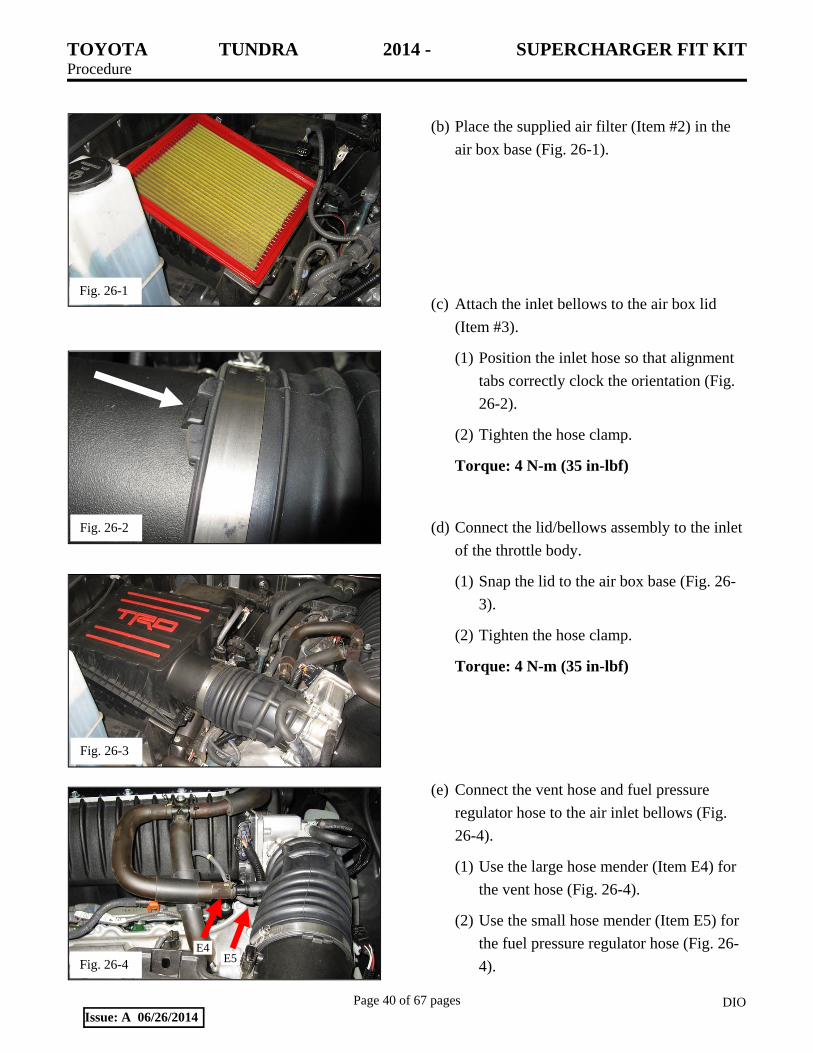
(b) Place the supplied air filter (Item #2) in the
air box base (Fig. 26-1).
(c) Attach the inlet bellows to the air box lid
(Item #3).
(1) Position the inlet hose so that alignment
tabs correctly clock the orientation (Fig.
26-2).
(2) Tighten the hose clamp.
Torque: 4 N-m (35 in-lbf)
(d) Connect the lid/bellows assembly to the inlet
of the throttle body.
(1) Snap the lid to the air box base (Fig. 26-
3).
(2) Tighten the hose clamp.
Torque: 4 N-m (35 in-lbf)
(e) Connect the vent hose and fuel pressure
regulator hose to the air inlet bellows (Fig.
26-4).
(1) Use the large hose mender (Item E4) for
the vent hose (Fig. 26-4).
(2) Use the small hose mender (Item E5) for
the fuel pressure regulator hose (Fig. 26-
4). Fig. 26-4 E5 E4

TOYOTA TUNDRA 2014 - SUPERCHARGER FIT KIT Procedure
Page 41 of 67 pages DIOIssue: A 06/26/2014
Fig. 26-5
Fig. 27-1
Fig. 27-2
Fig. 27-3
(f) Plug in the mass airflow (MAF) sensor and
clip the harness to the air box lid (Fig. 26-5).
27. Prepare to Install the Intercooler.
(a) Remove the low pitch horn.
(1) Disconnect the low pitch horn connector.
(2) Unbolt and remove the low pitch horn
(Fig. 27-1).
(3) Set the horn and bolt aside for reuse.
(b) Remove the high pitch horn.
(1) Disconnect the high pitch horn connector.
(2) Unbolt and remove the high pitch horn
(Fig. 27-2).
(3) Set the horn and bolt aside for reuse.
(c) Disconnect the connector and detach the
clamp (Fig. 27-3).
TOYOTA TUNDRA 2014 - SUPERCHARGER FIT KIT Procedure
Page 42 of 67 pages DIOIssue: A 06/26/2014
Fig. 27-4
Fig. 27-5
Fig. 27-6
Fig. 27-7
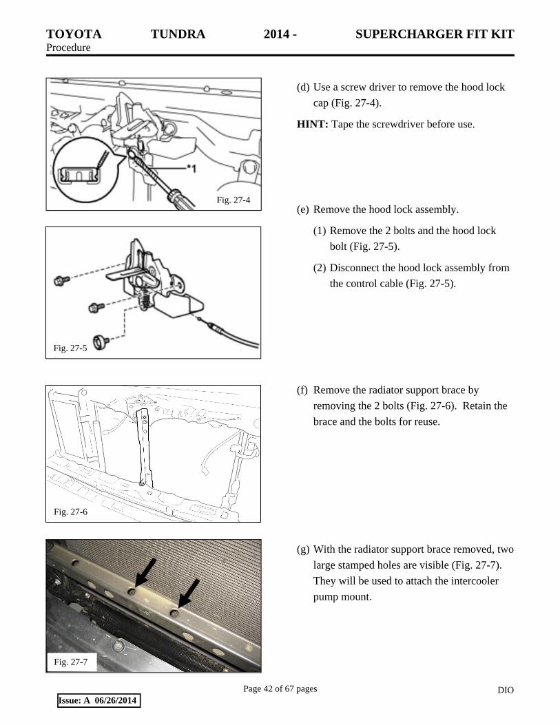
(d) Use a screw driver to remove the hood lock
cap (Fig. 27-4).
HINT: Tape the screwdriver before use.
(e) Remove the hood lock assembly.
(1) Remove the 2 bolts and the hood lock
bolt (Fig. 27-5).
(2) Disconnect the hood lock assembly from
the control cable (Fig. 27-5).
(f) Remove the radiator support brace by
removing the 2 bolts (Fig. 27-6). Retain the
brace and the bolts for reuse.
(g) With the radiator support brace removed, two
large stamped holes are visible (Fig. 27-7).
They will be used to attach the intercooler
pump mount.

TOYOTA TUNDRA 2014 - SUPERCHARGER FIT KIT Procedure
Page 43 of 67 pages DIOIssue: A 06/26/2014
Fig. 27-8
Fig. 28-1 Inlet
Outlet
Fig. 28-2
(h) Mount the intercooler pump bracket (Item
A4) to the lower radiator support with 2
rectangular body nuts (Item A6) and 2 M8
nuts (Item A5) (Fig. 27-8). Leave the bolts
finger tight for now.
HINT: The threaded holes in the nut plates are
chamfered on one side. Place the chamfer up to
make starting the bolts easier.
28. Install the Intercooler.
(a) Set the intercooler low temperature radiator
(LTR, Item #1) in front of the A/C condenser
(Fig. 28-1).
(1) Align the upper mounting tabs with the
horn mounting holes (top, Fig. 28-1 &
Fig. 28-2).

TOYOTA TUNDRA 2014 - SUPERCHARGER FIT KIT Procedure
Page 44 of 67 pages DIOIssue: A 06/26/2014
Fig. 28-3
Fig. 28-4
Fig. 28-5
Radiator Support Brace
#8 Adel Clamp (Item A21)
Wire Harness (Item A1)
Connector
OE Bolt
(2) Align the two rear M8 studs on the pump
mounting bracket (Fig. 28-3).
(3) Notice that the inlet and outlet of the
LTR are on the driver’s side of the
vehicle (Fig. 28-1).
(b) Secure the low temperature radiator by
reattaching the horns with the M8 Bolts
(Item A5) and M8 Hex Nuts (Item A8) (Fig.
28-4). Leave them finger tight for now.
(c) Lay the intercooler pump wire harness
assembly (Item A1) out on a table and place
the #8 Adel clamp (Item A21) 6” from the
end of the convoluted tubing on the
connector end (Fig. 28-5).
(d) Replace the radiator support brace removed
in Step 27(f).
(1) Place the OE bolt in the upper mounting
holes of the brace but do not tighten it
yet.
(2) Use the remaining OE bolt to secure the
lower end of the brace by placing it
through the Adel clamp.

TOYOTA TUNDRA 2014 - SUPERCHARGER FIT KIT Procedure
Page 45 of 67 pages DIOIssue: A 06/26/2014
Fig. 28-6
Forward
A8 A5
A6
A4
A7
A21
D1 45°
View from passenger’s side looking toward driver’s side
Fig. 28-8
D1
A13
B1
(3) The harness connector should be on the
passenger side of the vehicle with the
remainder of the harness stretched out
across the bumper toward the driver’s
side.
(4) Tighten all bolts and nuts.
Torque: M8 Bolt 20 N-m (15 ft-lbf)
M6 Bolt 8 N-m (71 in-lbf)
(e) Install the intercooler pump (Item D1) to the
pump bracket (Item A4) using the 2 #36 Adel
clamps (Item A7) and 2 M8 nuts (Item A8).
The pump outlet should be on the driver’s
side and angled up and back 45° (Fig. 28-6).
Torque: M8 Bolt 20 N-m (15 ft-lbf)
(f) The following 4 steps will plumb the
intercooler system (Fig. 28-7).
(g) Mark and cut a 4” x 18” section of molded
hose (Item B1) so that it connects the pump
outlet with the lower inlet on the LTR (Fig.
28-8).
(1) Secure the hose with 2 #10 hose clamps
(Item A13) (Fig. 28-8).
(2) The approximate lengths of the two legs
are 2.38” and 6.0.”
Fig. 28-7 Intercooler schematic

TOYOTA TUNDRA 2014 - SUPERCHARGER FIT KIT Procedure
Page 46 of 67 pages DIOIssue: A 06/26/2014
Fig. 28-9
Spring Clamps, A13
#10 Screw Clamps, A14
Fig. 28-10
B2 B8
Cut & remove shaded sections d
Wrap ends of split loom with electrical tape to hold it in place
Fig. 28-11
(h) Cut and discard 2” from the short leg of the
remaining 4” x 18” hose (Item B1).
(1) Secure this short leg to the driver’s side
nipple on the intercooler lid with a spring
clamp (Item A13) (Fig. 28-9).
(2) Route the long leg to the reservoir inlet,
mark and cut, and then secure it with a
#10 screw clamp (Item A14) (Fig. 28-9).
NOTE: Spring clamps (Item A13) are used
to secure all coolant hose ends except at
the reservoir where #10 screw clamps
(Item A14) are used.
(i) Trim the 4” x 60” hose (Item B2) to 2” x 53”
(Fig. 28-10).
(1) Cut a 42” length of 1” split loom (Item
B8) and apply it to the hose 2” from the
straight end (Fig. 28-10).
(2) Wrap the ends of the split loom with
electrical tape to hold it in place (Fig. 28-
10).
(3) Attach the short leg of the hose assembly
to the passenger side nipple on the
intercooler lid using a spring clamp (Item
A13) (Fig. 27-9).
(4) Route the long leg through the top cutout
in the LH radiator side shield (refer to
Fig. 9-2) and attach it to the upper outlet
on the LTR with a spring clamp (Item
A13) (Fig. 28-11).

TOYOTA TUNDRA 2014 - SUPERCHARGER FIT KIT Procedure
Page 47 of 67 pages DIOIssue: A 06/26/2014
Fig. 28-12
Fig. 28-13
A13 B8
A15 A1
B3 Inlet
Fig. 28-14
Fig. 28-15
B9
(j) Secure the 2 hoses coming from the
intercooler lid together with a 7.5” tie wrap
(Item A15) (Fig. 28-12).
(k) Place the remaining 42” of 1” split loom
(Item B8) on the 48” long straight hose (Item
B3).
(1) Connect one end to the lower outlet of
the reservoir with a #10 screw clamp
(Item A14) (Fig. 28-11).
(2) Route the other end down through the
bottom cut out in the LH radiator side
shield (refer to Fig. 9-2) and connect it to
the pump inlet with a spring clamp (Item
A13) (Fig. 28-13).
(l) Secure the pump wire harness (Item A1) to
the coolant hose assembly with a tie wrap
(Item A15) (Fig. 28-13).
(m) Plug the electrical connector into the pump
(Fig. 28-14).
(n) Place the ½” X 6” split loom (Item B9) over
the fuel line (Fig. 28-15).

TOYOTA TUNDRA 2014 - SUPERCHARGER FIT KIT Procedure
Page 48 of 67 pages DIOIssue: A 06/26/2014
Fig. 28-16
Fig. 29-1
(o) Use 2 swivel spacers (Item A18) and 4 tie
wraps (Item A16) to mount the two coolant
hoses and the AC line together (Fig. 28-16).
NOTE: The insert shows how 2 lines are
coupled. Do this twice so all three lines are
tied together.
29. Install the Electrical Wiring.
(a) Route the free end of the pump wire harness
(Item A1) toward the driver’s side of the
vehicle and up under the headlight to the
back of the battery tray (Fig. 29-1 through
Fig. 29-3).
(1) The circle in Fig. 29-1 shows where the
harness will pass under the headlight
back into the engine compartment.
(2) Use tie wraps (Item A15) to secure the
harness.
Fig. 29-2
A1A15
A15
Fig. 29-3
A1 A15

TOYOTA TUNDRA 2014 - SUPERCHARGER FIT KIT Procedure
Page 49 of 67 pages DIOIssue: A 06/26/2014
Fig. 29-7
(b) Remove bolt “A” and screw it into the
fuse/relay assembly that is part of the wire
harness (Item A1) (Fig. 29-4 & Fig. 29-5).
(c) Make sure the bolt goes through the black
ground wire eyelet first, then the metal
bracket of the relay, and finally the fuse
bracket as shown (Fig. 29-5).
(d) Install the 15A fuse (Item A2) into the fuse
holder (Fig. 29-6).
(e) Reinstall the ground bolt, with the assembly
now attached, back into grounding point “A”
(Fig. 29-4 & Fig. 29-6).
Torque: 10 N-m (88 in-lbf)
(f) Route the yellow wire of the relay wire
harness (Item A1) into the vehicle fuse box
through opening “B” (Fig. 29-4 & Fig. 29-7).
Fig. 29-4
A
B
Fig. 29-5
Fig. 29-6
Install 15A fuse into fuse holder

TOYOTA TUNDRA 2014 - SUPERCHARGER FIT KIT Procedure
Page 50 of 67 pages DIOIssue: A 06/26/2014
Fig. 29-9
Fig. 29-10
Original Replacement
(g) Remove the 10 amp ignition fuse (Fig. 29-8
& Fig. 29-9).
(h) The original (removed) fuse and the new
replacement fuse (Item A3) are shown in Fig.
29-10).
Fig. 29-8

TOYOTA TUNDRA 2014 - SUPERCHARGER FIT KIT Procedure
Page 51 of 67 pages DIOIssue: A 06/26/2014
Fig. 29-11
Fig. 29-12
Fuse tap goes toward the rear of vehicle.
Fig. 29-14
(i) The yellow wire that was routed into the
vehicle fuse box has a fuse tap on the end.
Connect the fuse tap onto the new
replacement fuse (Fig. 29-11).
(j) Insert the new fuse connected to the yellow
wire in place of the removed fuse. The
yellow wire side of the fuse goes toward
the rear of the vehicle (Fig. 29-12).
(k) Route the main length of the relay wire
harness along the battery ground cable and
secure it using the short tie wrap (Item A15)
(Fig. 29-13).
(l) Add a short tie wrap (Item A15) at the end of
the cover over the yellow wire as shown
(Fig. 29-13).
(m) Route the red B+ wire of the relay wire
harness up to the main battery B+ terminal
and secure it with the plastic cover that clips
to the cable (Fig. 29-14).
(n) Reinstall all of the parts removed in Steps 4
through 8 (Hood, Wiper Motor & Link, Cowl
Top Outer Panel, Radiator Grille and Front
LH End Panel).
Fig. 29-13

TOYOTA TUNDRA 2014 - SUPERCHARGER FIT KIT Procedure
Page 52 of 67 pages DIOIssue: A 06/26/2014
30. Remove the OE In-Tank Fuel Pump Assembly.
(a) Discharge the fuel system pressure.
(b) Remove the fuel tank cap.
(c) If required, remove the fuel tank protector by
removing the 2 bolts & 2 nuts (Fig. 30-1).
(d) Disconnect the fuel tank feed and return tube
sub-assemblies.
(1) Lift up the cover to detach the lock claw
(Fig. 30-2).
(2) Pinch and pull the main tube connector to
disconnect it from the pipe (Fig. 30-3).
NOTE: Do not force, bend or use tools
when separating the tubes. Make sure all
mating surfaces are clean. Do not kink
the nylon fuel lines. If any kinks or other
damage occurs during removal or
installation of the fuel lines, replacement
of the damaged fuel line is REQUIRED.
Fig. 30-1
Fig. 30-2
Fig. 30-3

TOYOTA TUNDRA 2014 - SUPERCHARGER FIT KIT Procedure
Page 53 of 67 pages DIOIssue: A 06/26/2014
(e) Pull up on the retainer clip to disconnect the
vent line hose (Fig. 30-4).
(f) Disconnect the wire harness from the fuel
tank (Fig. 30-5).
(g) Disconnect the fuel tank breather tube “A”
from the inlet pipe (Fig. 30-6).
(h) Disconnect the fuel tank to filler pipe hose
“B” from the inlet pipe (Fig. 30-6).
(i) Disconnect the outlet canister hose “C” from
the inlet pipe (Fig. 30-6).
A
B
C
Fig. 30-6
Fig. 30-4
Fig. 30-5

TOYOTA TUNDRA 2014 - SUPERCHARGER FIT KIT Procedure
Page 54 of 67 pages DIOIssue: A 06/26/2014
(j) Detach the breather tube, filler pipe hose and
outlet canister hose from the No. 1 breather
tube clamp (Fig. 30-7).
(k) Set a mission jack underneath the fuel tank.
(l) Remove the 2 bolts, 2 clips, 2 pins and 2 fuel
tank bands (Fig. 30-8).
(m) Slowly lower the fuel tank and disconnect
the fuel pump connector (Fig. 30-9).
(n) Slowly continue to lower the fuel tank to
access the fuel pump assembly.
Fig. 30-7
Fig. 30-8
Fig. 30-9

TOYOTA TUNDRA 2014 - SUPERCHARGER FIT KIT Procedure
Page 55 of 67 pages DIOIssue: A 06/26/2014
(o) Remove the 2 joint clips on the fuel tank
tubes and then remove the tubes (Fig. 30-10).
(p) Use a SST to loosen and remove the fuel
pump retainer ring (Fig. 30-11).
SST: 09808-14020
(09080-01410)
(09080-01420)
(09080-01430)
(q) Remove the fuel pump assembly from the
fuel tank (Fig. 30-12).
Fig. 30-10
Fig. 30-11
Fig. 30-12
TOYOTA TUNDRA 2014 - SUPERCHARGER FIT KIT Procedure
Page 56 of 67 pages DIOIssue: A 06/26/2014
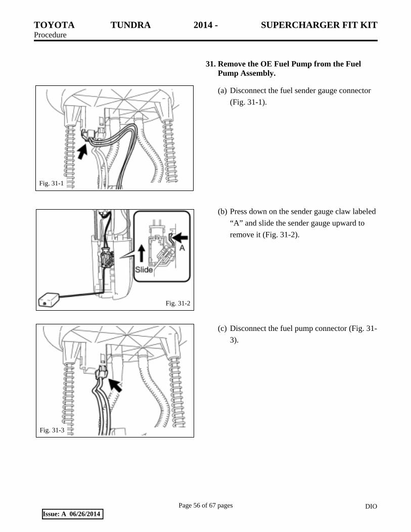
31. Remove the OE Fuel Pump from the Fuel Pump Assembly.
(a) Disconnect the fuel sender gauge connector
(Fig. 31-1).
(b) Press down on the sender gauge claw labeled
“A” and slide the sender gauge upward to
remove it (Fig. 31-2).
(c) Disconnect the fuel pump connector (Fig. 31-
3).
Fig. 31-1
Fig. 31-2
Fig. 31-3

TOYOTA TUNDRA 2014 - SUPERCHARGER FIT KIT Procedure
Page 57 of 67 pages DIOIssue: A 06/26/2014
(d) Use a small screwdriver to detach the claw
on the end of the tube from the claw hole.
Disconnect the tube from the 2 clamps (Fig.
31-4).
(e) Disconnect the fuel tube (Fig. 31-5).
(f) Use a small screwdriver to detach the 3 claws
from the claw holes (Fig. 31-6).
Fig. 31-4
Fig. 31-5
Fig. 31-6

TOYOTA TUNDRA 2014 - SUPERCHARGER FIT KIT Procedure
Page 58 of 67 pages DIOIssue: A 06/26/2014
(g) Use a small screwdriver to detach the 2 claws
from the claw holes and remove the sub tank
(Fig. 31-7).
(h) Use a small screwdriver to detach the 5 claws
from the claw holes and disconnect the fuel
pump from the suction plate with filter (Fig.
31-8).
(i) Disconnect the fuel pump harness from the
fuel pump (Fig. 31-9).
Fig. 31-7
Fig. 31-8
Fig. 31-9

TOYOTA TUNDRA 2014 - SUPERCHARGER FIT KIT Procedure
Page 59 of 67 pages DIOIssue: A 06/26/2014
(j) Remove the fuel pump discharge O-ring and
spacer from the fuel pump (Fig. 31-10).
NOTE: The old O-Ring can be discarded. A
new fuel pump discharge O-Ring is included
in the installation kit (Item J3). The spacer
will be reused with the new fuel pump.
32. Install the New Fuel Pump into the Fuel Pump Assembly.
(a) Apply a light coat of gasoline to the new O-
ring (Item J3). Install the spacer and O-ring
onto the supplied fuel pump(Item F3) (Fig.
32-1).
NOTE: Make sure the new O-ring and spacer
are installed as shown. Reversal of the O-ring
and spacer will result in low fuel system
pressure, causing possible engine damage.
(b) Install the new fuel pump into the fuel pump
assembly in the exact opposite order used to
remove the OE pump in Step 31.
33. Reinstall the Fuel Pump Assembly and Fuel
Tank.
(a) Reinstall the fuel pump assembly and fuel
tank in the exact opposite order that was used
to remove it in Step 30.
Fig. 31-10
Fig. 32-1

TOYOTA TUNDRA 2014 - SUPERCHARGER FIT KIT Procedure
Page 60 of 67 pages DIOIssue: A 06/26/2014
(b) Make sure to use the new fuel pump module
O-Ring (Item J1) supplied in the kit when
installing the fuel pump assembly into the
fuel tank (Fig. 33-1).
(c) When reinstalling the fuel tank assembly, use
the torque specifications indicated in Fig. 33-
2.
34. Prepare for Vehicle Start-up.
(a) Pour the coolant saved in Step 3 into the
radiator until it is full.
(1) Use of improper coolant may damage the
engine cooling system.
(2) Use Toyota Super Long Life Coolant or
similar high quality ethylene glycol based
non-silicate, non-amine, non-nitrate, and
non-borate coolant with long-life hybrid
organic acid technology.
Fig. 33-1
Fig. 33-2 29 N-m (21 ft-lbf) 20 N-m (15 ft-lbf)
40 N-m (30 ft-lbf)

TOYOTA TUNDRA 2014 - SUPERCHARGER FIT KIT Procedure
Page 61 of 67 pages DIOIssue: A 06/26/2014
(3) New Toyota vehicles are filled with
Toyota Super Long Life Coolant (color is
pink, premixed ethylene glycol
concentration is approximately 50% and
freezing temperature is -35°C (-31°F)).
When replacing and/or adding coolant,
Toyota Super Long Life Coolant is
recommended.
NOTICE: Do not substitute plain water for
engine coolant.
(b) Check the coolant level inside the radiator by
squeezing the inlet and outlet radiator hoses
several times by hand. If the coolant level
goes down, add coolant.
(c) Install the radiator cap.
(d) Slowly pour coolant into the radiator
reservoir until it reaches the FULL line.
(e) FILL THE INTERCOOLER
RESERVOIR: Fill the intercooler reservoir
with the same coolant as the vehicle radiator.
(f) Reinstall and connect the battery.
Torque: 5.4 N-m (48 in-lbf)
(g) Once the intercooler reservoir is full and will
not take any more coolant, turn the ignition
key to ON, but do not start the engine.
(1) The intercooler pump will run and purge
air from the intercooler system.
(2) Continue to add coolant to the intercooler
reservoir until it is full.

TOYOTA TUNDRA 2014 - SUPERCHARGER FIT KIT Procedure
Page 62 of 67 pages DIOIssue: A 06/26/2014
(h) Place the new vacuum and belt routing label
(Item H8) and CARB EO Emissions label
(Item H9) on an open area on the underside
of the hood (Fig. 34-1).
(1) Clean the area of any dirt and
contaminants.
(2) DO NOT cover any OE labels.
(3) Place the CARB OE Emissions label near
the vacuum and belt routing label.
(4) If your state requires an Emissions
Compliance Label, one may be ordered
through your Toyota dealer or the
Toyota Materials Distribution Center
(MDC) 310-468-9800 or
(i) Install the Premium Fuel Only decals (Item
H3).
(1) Place one decal on the dash near the fuel
gauge.
(2) Place one decal near the fuel filler cap.
(j) Prime the fuel system.
(1) Prime the fuel lines and fuel rails before
attempting to start the engine for the first
time.
(2) Failure to do so will cause hard-starting
for the first few tries and may trigger
false MIL lights.
(3) Use the TIS Techstream to connect to the
vehicle and select the “ENG and ECT”
ECU from the list of ECUs.
(4) Select “Active Test” from the menu
selection on the left of the screen.
Fig. 34-1
TOYOTA TUNDRA 2014 - SUPERCHARGER FIT KIT Procedure
Page 63 of 67 pages DIOIssue: A 06/26/2014
(5) Select the test “Control the Fuel
Pump/Speed” from the list of tests and
click “OK.”
(6) The screen will show a data list and a
small window that tells the status of the
fuel pump. Initially, the fuel pump will
be “OFF”. Turn the fuel pump on and let
it run for about 3 minutes. You can use
this time to check for any fuel system
leaks.
(7) When priming is complete, exit the test
and prepare for ECU re-flashing.
NOTE: The fuel system priming function
was written for use with TIS Techstream
v9.00.026. If you do not have TIS
Techstream, then consult with the
manufacturer of the scan tool you are
using to perform the fuel priming
function.
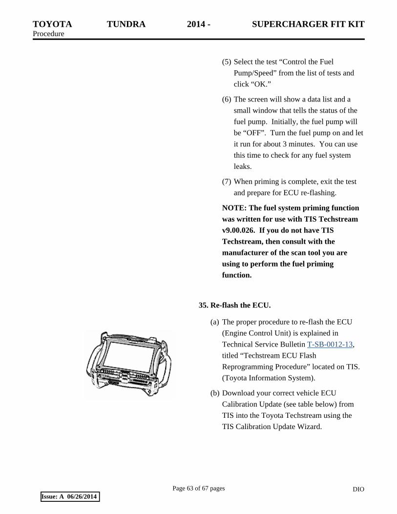
35. Re-flash the ECU.
(a) The proper procedure to re-flash the ECU
(Engine Control Unit) is explained in
Technical Service Bulletin T-SB-0012-13,
titled “Techstream ECU Flash
Reprogramming Procedure” located on TIS.
(Toyota Information System).
(b) Download your correct vehicle ECU
Calibration Update (see table below) from
TIS into the Toyota Techstream using the
TIS Calibration Update Wizard.

TOYOTA TUNDRA 2014 - SUPERCHARGER FIT KIT Procedure
Page 64 of 67 pages DIOIssue: A 06/26/2014
(c) Follow the re-flashing procedure outlined in
T-SB-0012-13.
NOTE: Use Techstream v9.00.026 or later.
NOTE: The GR8 Battery Charger MUST be
used in Power Supply Mode to maintain
battery voltage at 13.5 volts while flash
reprogramming the vehicle.
For details on how to use the GR8 Battery
Charger please refer to the GR8 Instructions
Manual located on TIS, Diagnostics-Battery.
NOTE: The vehicle WILL NOT operate
properly without this ECU update.
Model Engine Year Drive Tow
Package Target
Calibration SC Calibration
Tundra 3UR-FE 5.7L V-8
2014 2WD
NO 30CL0000 3YWF7800 YES 30CL1000 3YWF7900
4WD NO 30CL0001 3YWF7801 YES 30CL1001 3YWF7901
36. Test and Evaluate.
(c) IMPORTANT: Check the serpentine belt
drive systems for correct alignment on ALL
pulleys before starting the engine.
(d) Start the engine and let it idle.
(e) Check the fuel system for any leaks.
(f) Check the coolant system for any leaks.
(1) Set the A/C system as follows:
Fan Speed Any setting except OFF
Temperature Toward Warm
A/C Switch OFF
(2) Maintain the engine speed at 2,000 to
2,500 rpm and warm up the engine until
the cooling fan operates.

TOYOTA TUNDRA 2014 - SUPERCHARGER FIT KIT Procedure
Page 65 of 67 pages DIOIssue: A 06/26/2014
(3) Squeeze the inlet and outlet radiator
hoses several times by hand while
warming up the engine.
(g) Check the air intake system to ensure no
leaks are present and for tightness of the
clamps.
(h) Stop the engine and wait for the coolant to
cool down.
(i) Carefully remove the radiator cap and check
the coolant level inside the radiator and add
coolant if necessary. Reinstall the radiator
cap.
(j) Check the coolant level inside the radiator
reservoir. If it is below the full level, add
coolant.
(k) Check the coolant in the intercooler reservoir
and add coolant if necessary.
(l) Test drive the vehicle. If everything is okay,
park and proceed with the next step. If not,
troubleshoot as necessary.
(m) Use the Techstream diagnostic to check for
ECU error codes.
(n) Place the supercharger noise mirror hanger
card (Item H7) on the inside rearview mirror.
(o) Complete and mail the warranty registration
card (Item H6).
NOTE: The installation of the supercharger is not complete until this card has been returned to TRD.
(p) Place all removed factory hardware,
components, and this instruction sheet into
the original TRD box and give it to the
customer or place it in the vehicle cargo
compartment.

TOYOTA TUNDRA 2014 - SUPERCHARGER FIT KIT Procedure
Page 66 of 67 pages DIOIssue: A 06/26/2014
(q) IMPORTANT: Review with the
customer/end-user that the supercharger will
make a slight noise at idle that increases as
the throttle is opened and that this is normal.
(r) IMPORTANT: Review with the
customer/end-user that it is it is imperative
that only 91octane or higher fuel be used
after the supercharger is installed.
Performance will suffer and engine damage
is possible otherwise.
(s) Place this copy (or a clean copy) of
supercharger installation instructions into the
glove box for future owner use or reference.
(t) your state requires an Emissions
Compliance Label, one may be ordered
through your Toyota dealer or the Toyota
Materials Distribution Center (MDC) 310-
468-9800 or [email protected].
(u) This TRD Supercharger Kit has received a
50-State Emissions Compliance via the
California Air Resources Board (CARB).
Not all states require the Emissions
Compliance Label but TRD does recommend
ordering one. To receive the proper
Supercharger Emissions Compliance Label
for this TRD Supercharger kit, please order
MDC label part number 00602-34155 which
will apply to 2005-2014 Toyota Tundra with
5.7L V-8 Gasoline Only engines. Proof of
product purchase or ownership may be
required.

TOYOTA TUNDRA 2014 - SUPERCHARGER FIT KIT Checklist - these points MUST be checked to ensure a quality installation.
Check: Look For:
Page 67 of 67 pages DIOIssue: A 06/26/2014
Accessory Function Checks
Proper fuel used All fluid levels & leaks Serpentine belt alignment Fuel line connections Engine fan clutch clearance Engine ECU re-flash
Vehicle Function Checks
Fuel leaks Coolant leaks Drive test
Use 91 octane unleaded fuel (R+M /2) Inspect engine cooling system and supercharger cooling system for proper fluid type and level Inspect serpentine drive belts for proper alignment, tension, and clearance from engine compartment items. Inspect all fuel rails, injectors, injector seals, pressure regulator, and fuel line connectors for leaks Inspect engine fan clutch for free movement and clearance from radiator Ensure the proper calibration file was used for the vehicle No Fuel leaks are present No coolant leaks are present Vehicle starts up easily, no DTC trouble codes are present, and drivability is smooth and predictable; place copy of installation instructions into glove box for customer use and reference
Vehicle Appearance Check
After accessory installation and removal of protective cover(s), perform a visual inspection.
Ensure no damage (including scuffs and scratches) was caused during the installation process. (For PPO installations, refer to TMS Accessory Quality Shipping Standard.)