Embed Size (px)
Citation preview

READ ME FIRST
TECHNICAL SUPPORT 1-800-FORD-KEY
CANADIAN DEALERSBILINGUAL FRENCH/ENGLISH
TECHNICAL SUPPORT (514)973-2846
For convenience this document uses short names when referring to a particular system or kit. The list below identifies the short names used herein: Vehicle Security System >VSS
Navigating this document can be accomplished by: 1) using the buttons in the Acrobat toolbar or 2) clicking on the bookmark links in the bookmark pane to the left. (Clicking on the (+) symbols next to a bookmark will expand that bookmark, revealing additional selections).
This installation instruction covers the installation of all Vehicle Security System Kits.
Vehicle wiring is subject to change. All possible efforts have been taken to ensure that the information contained herein is accurate as of the revision dates indicated. As such, it is critical that vehicle circuits are tested prior to making any connections, to ensure that the proper vehicle circuit has been located.
Prior to beginprevent locking the keys in the vehicle.Prior to beginning your first installation of this product it is recommended that you:
1 Thoroughly review and print out the instructions; 2 Review the reference section to become acquainted with the additional information that is
available. 3 Go through the vehicle specific wiring and use as a reference during the installation.4 Review the installation video on the Ford Genuine Accessory website that is located with the
VSS Installation Instructions.
Page 1 of 2 JSK9L3J-19A361-AA © Copyright Ford 2012
Page 2 of 2 SK9L3 J-19A361-AA © Copyright Ford 2012
Ford Accessory Vehicle Security, Keyless Entry and Remote Start
Warranty Return Procedures
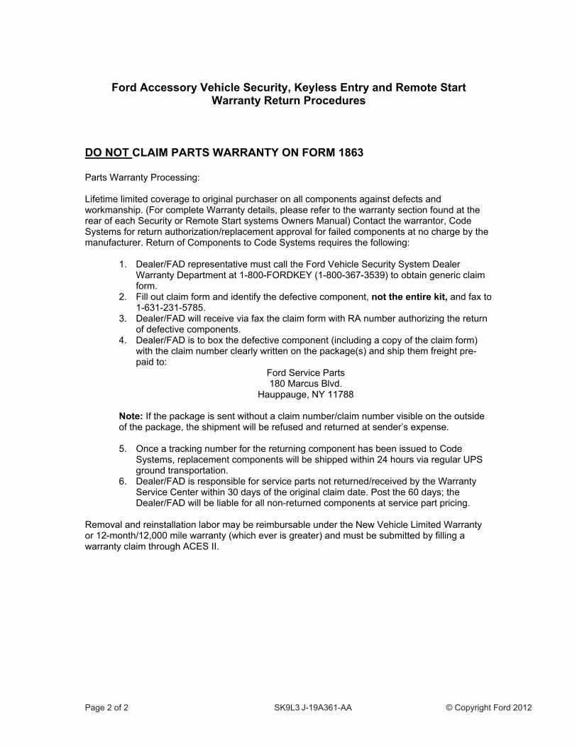
DO NOT CLAIM PARTS WARRANTY ON FORM 1863 Parts Warranty Processing: Lifetime limited coverage to original purchaser on all components against defects and workmanship. (For complete Warranty details, please refer to the warranty section found at the rear of each Security or Remote Start systems Owners Manual) Contact the warrantor, Code Systems for return authorization/replacement approval for failed components at no charge by the manufacturer. Return of Components to Code Systems requires the following:
1. Dealer/FAD representative must call the Ford Vehicle Security System Dealer Warranty Department at 1-800-FORDKEY (1-800-367-3539) to obtain generic claim form.
2. Fill out claim form and identify the defective component, not the entire kit, and fax to 1-631-231-5785.
3. Dealer/FAD will receive via fax the claim form with RA number authorizing the return of defective components.
4. Dealer/FAD is to box the defective component (including a copy of the claim form) with the claim number clearly written on the package(s) and ship them freight pre-paid to:
Ford Service Parts 180 Marcus Blvd.
Hauppauge, NY 11788
Note: If the package is sent without a claim number/claim number visible on the outside of the package, the shipment will be refused and returned at sender’s expense.
5. Once a tracking number for the returning component has been issued to Code
Systems, replacement components will be shipped within 24 hours via regular UPS ground transportation.
6. Dealer/FAD is responsible for service parts not returned/received by the Warranty Service Center within 30 days of the original claim date. Post the 60 days; the Dealer/FAD will be liable for all non-returned components at service part pricing.
Removal and reinstallation labor may be reimbursable under the New Vehicle Limited Warranty or 12-month/12,000 mile warranty (which ever is greater) and must be submitted by filling a warranty claim through ACES II.
����������� ��� �
����������������� ���������������������� �� ���������������
������������� ������ ������������������ ������ ��������
���������������� ������ ���������������������������� �������������������� ����
����� ���� ��� �� ������ ���������� �������
�������������������� ����������������� �������� ����������� �����������������������
�� ������� ������������� ��������������������������������������������������������� ���
!� "���������� ����������������� �������#������������ �����������������������������
$� "���������� ����������������� �������#���������������������������������������������� ���
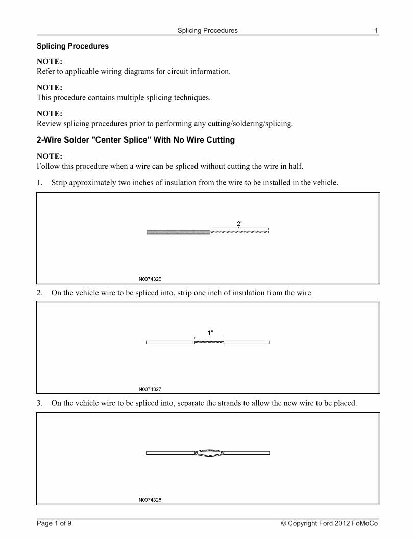
Splicing Procedures 1
Page 1 of 9 © Copyright Ford 2012 FoMoCo
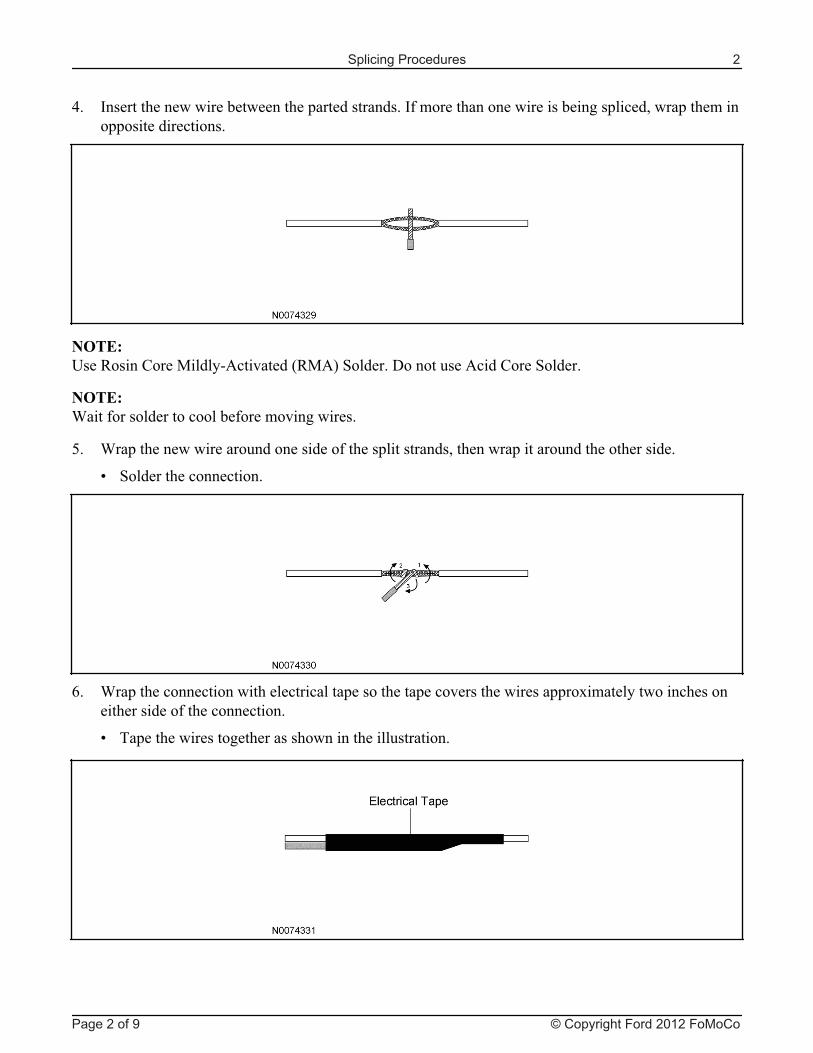
%� &��������������������������������������������&�������������������������������� ��#���������������������� ������
������'���������(����)�����*+ �������,�)+-���������.����������+ ���(�����������
������/����������������� ������������������������
0� /������������������������������������������������#���������������������������������
1 ����������� ���� �����
2� /������ ���� ������������� ��� ��������������� ������������������ ������������� ������������������������� ���� �����
1 �������������������������������������������������
Splicing Procedures 2
Page 2 of 9 © Copyright Ford 2012 FoMoCo
����� ���� ������ ������ ������������������ ��� ���
�����������3*�%�+/4�'�������������������� �������(������������ ��5�� �������
������������� ����5�� ������'���/������� �������6���,�2%*�073$-�
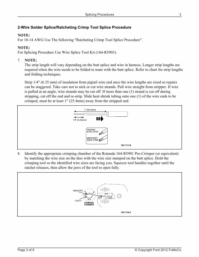
8� ������������������������������������������������������� ������������������������������������������������������������������������������������������������������������� ������������ ��������������������������������� ��������
�������%9�,2�$0���-������������������������������������ ������������������������:����������� ����������������;�� ������������ ;���� ����������������5������������������������������&�����������������������#������������������� ��������&���������������,�-���������� ��������������������#� ��������������������*���������������������;�����������������,�-����������������������� �����#�����������������9�,!0�%��-������������������������
<� &������������������� ������� ���������������������2%*�073��5��*(������,������������-����� ����������������:������������������������������:����������������������� ���=������� �������������������������������������:������� ��������������:���������������������������������� �����������#���������������>����������������������������
Splicing Procedures 3
Page 3 of 9 © Copyright Ford 2012 FoMoCo
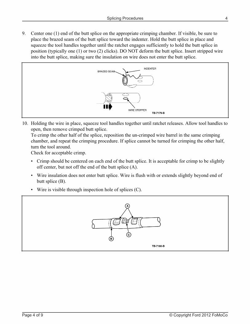
7� (����������,�-�������������������� ���������������� ������� �������&���������#������������ ��������:���������������������� ����������������������=���������������� ������ ���������:��������������������������������������� ���������������� ��������������������������� ������������,��� ��������,�-��������,!-� �� ;�-��."�?"��������������������� ���&���������������������������������� �#��;���������������������������������������������������������� ��
�3� =�������������������� �#������:������������������������������� �������������+����������������������#������������� �������������� ����� ���������������������������� �#�����������������* ���������������������������� ������ �����#������������� ��������� �������&����� �� ������������������� ��������������������#��������������������(�� ;����� ������ ����
1 (�������������� ������������ ��������������������� ���&����� ���������� ���������������������� �����#������������������������������������ ��,+-�
1 /������������������������������������� ���/���������������������� ������������������������������������ ��,@-�
1 /��������������������������� ���������������� ���,(-�
Splicing Procedures 4
Page 4 of 9 © Copyright Ford 2012 FoMoCo
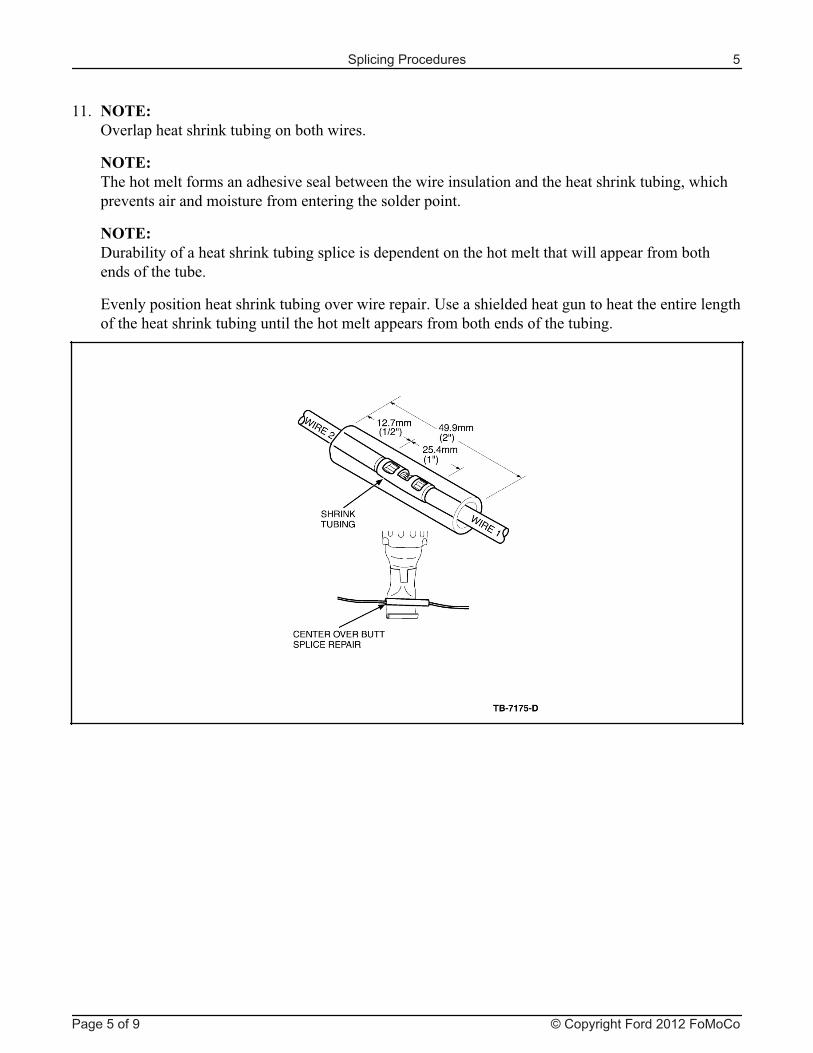
��� ������"��������������;����������������������
����������������������������������������������������������������������������������;�������#���� ������������������������������������������������������
������.����������������������;����������� ��������������������������������������������������������������������
A�����������������������;������������������������'�������������������������������������������������������������;������������������������������������������������������������
Splicing Procedures 5
Page 5 of 9 © Copyright Ford 2012 FoMoCo
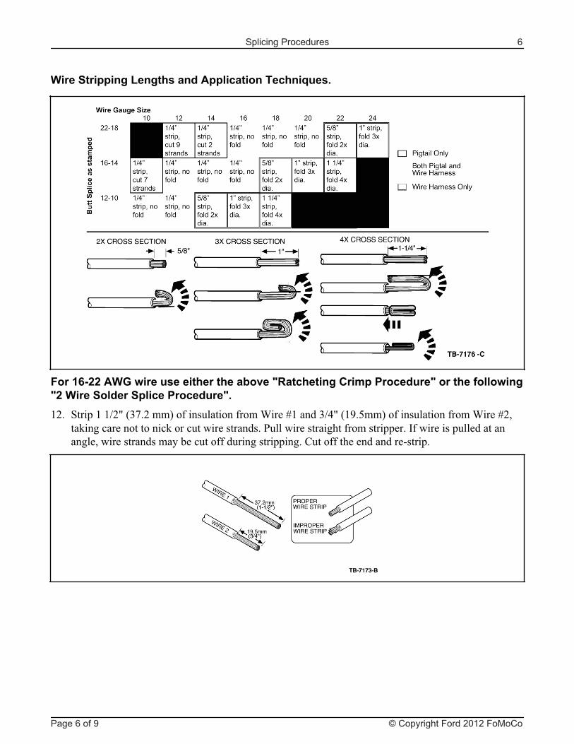
���� ���!�"#�� �� ��� ��� �$�% ������ ������������ ��� ����� &����#�������� ���� ������ ��� ��� �'�!� ���������!9�,$8�!���-�������������������/����B�����$�%9�,�7�0��-�������������������/����B!#
�;���� ������������ ;���� ����������������5������������������������������&�����������������������#������������������� �����������������������(��������������������*�����
��� ���������( ��������!����������� ����)� �'
Splicing Procedures 6
Page 6 of 9 © Copyright Ford 2012 FoMoCo
����������������������������������������������������������������������������;�������#���� ������������������������������������������������������
&���������������;����������������9�,!2���-����������������������������������������� ����������������������������������������������������@����/����B��� ;�����������������������������&��� ���������>�����������A�����������������������;������������������������'�������������������������������������������������������������;�����������������������������������������������������������
*���� ���� ������ ��� ��� �%� ���������!9�,$8�!���-���������������������������������/����B�����$�%9�,�7���-�������������
�����/����B!#��;���� ������������ ;���� ����������������5������������������������������&�����������������������#������������������� �����������������������(��������������������*�����
�$� ������'��������� ����������� �������,�)�-�������������������� ��� �������������������������
������"����������������������������������������������� ����������������������������
������.����������������������;����������� ��������������������������������������������������������������������
������
Splicing Procedures 7
Page 7 of 9 © Copyright Ford 2012 FoMoCo
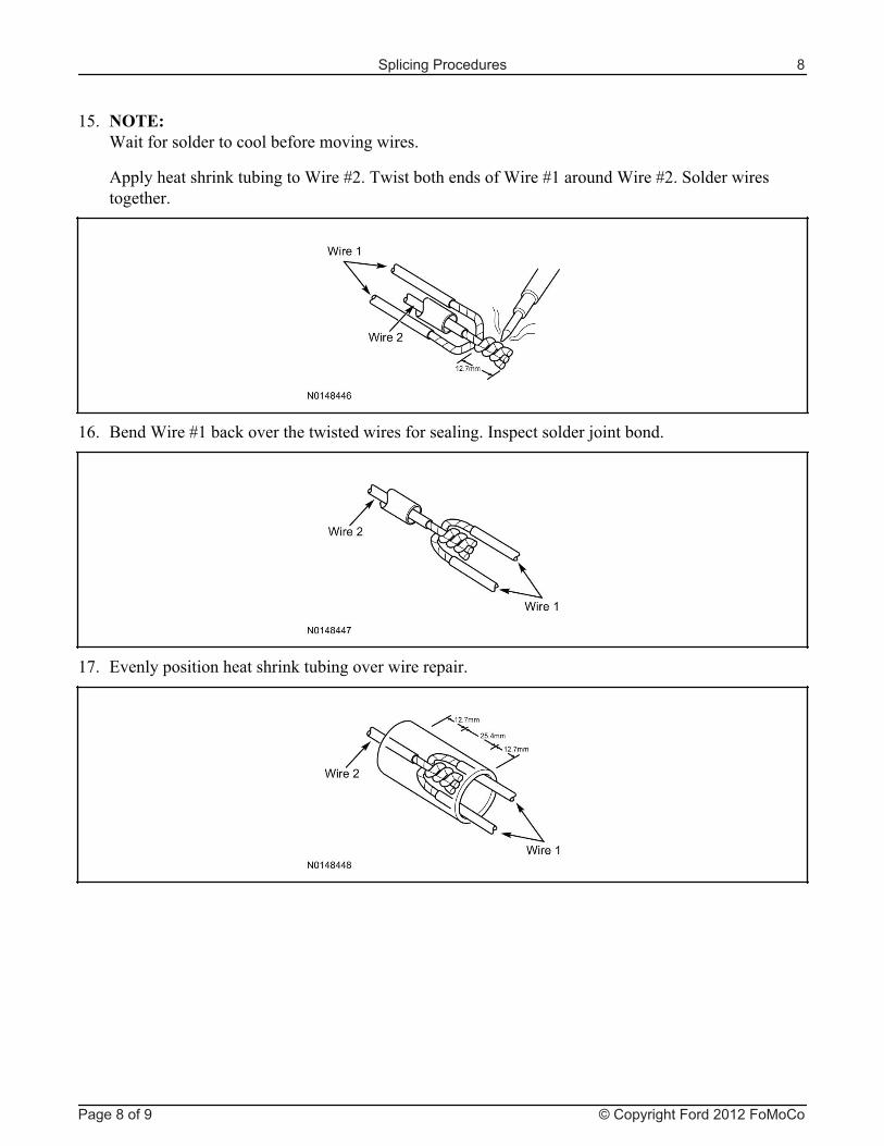
�2� @����/����B��� ;������������������������������������&��� ���������>����������
�8� A�����������������������;�����������������������
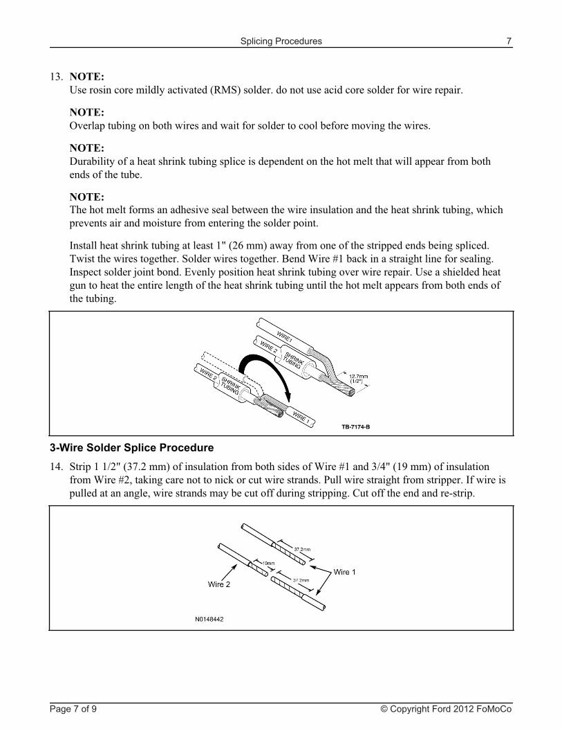
�0� ������/����������������� ������������������������
+������������;�����������/����B!���������������������/����B��������/����B!�����������������������
Splicing Procedures 8
Page 8 of 9 © Copyright Ford 2012 FoMoCo
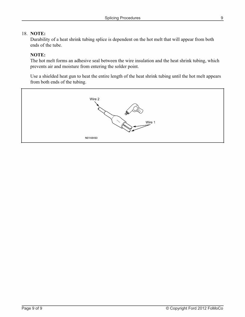
�<� ������.����������������������;����������� ��������������������������������������������������������������������
����������������������������������������������������������������������������������;�������#���� ������������������������������������������������������
'��������������������������������������������������������������;�����������������������������������������������������������
Splicing Procedures 9
Page 9 of 9 © Copyright Ford 2012 FoMoCo
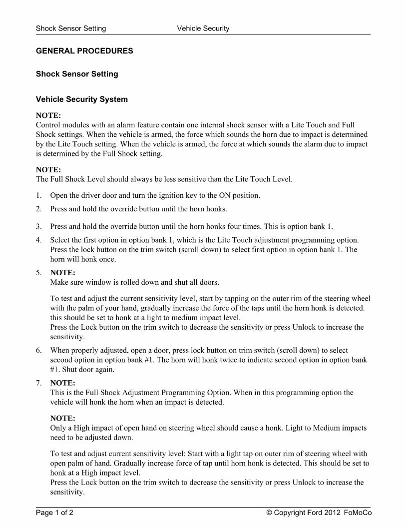
GENERAL PROCEDURES
Shock Sensor Setting
Vehicle Security System
NOTE: Control modules with an alarm feature contain one internal shock sensor with a Lite Touch and FullShock settings. When the vehicle is armed, the force which sounds the horn due to impact is determinedby the Lite Touch setting. When the vehicle is armed, the force at which sounds the alarm due to impactis determined by the Full Shock setting.
NOTE: The Full Shock Level should always be less sensitive than the Lite Touch Level.
1. Open the driver door and turn the ignition key to the ON position.
2. Press and hold the override button until the horn honks.
3. Press and hold the override button until the horn honks four times. This is option bank 1.
4. Select the first option in option bank 1, which is the Lite Touch adjustment programming option.Press the lock button on the trim switch (scroll down) to select first option in option bank 1. Thehorn will honk once.
5. NOTE: Make sure window is rolled down and shut all doors.
To test and adjust the current sensitivity level, start by tapping on the outer rim of the steering wheelwith the palm of your hand, gradually increase the force of the taps until the horn honk is detected.this should be set to honk at a light to medium impact level.Press the Lock button on the trim switch to decrease the sensitivity or press Unlock to increase thesensitivity.
6. When properly adjusted, open a door, press lock button on trim switch (scroll down) to selectsecond option in option bank #1. The horn will honk twice to indicate second option in option bank#1. Shut door again.
7. NOTE: This is the Full Shock Adjustment Programming Option. When in this programming option thevehicle will honk the horn when an impact is detected.
NOTE: Only a High impact of open hand on steering wheel should cause a honk. Light to Medium impactsneed to be adjusted down.
To test and adjust current sensitivity level: Start with a light tap on outer rim of steering wheel withopen palm of hand. Gradually increase force of tap until horn honk is detected. This should be set tohonk at a High impact level.Press the Lock button on the trim switch to decrease the sensitivity or press Unlock to increase thesensitivity.
Shock Sensor Setting Vehicle Security
Page 1 of 2 © Copyright Ford 2012 FoMoCo
8. Turn the ignition key to the OFF position.
9. Arm the system and check the new settings.
GENERAL PROCEDURESShock Sensor Setting Vehicle Security
Page 2 of 2 © Copyright Ford 2012 FoMoCo

2013 Explorer - Key Start Vehicle Security
Manual Table of Contents
VSS SYSTEM INSTALLATIONCONTENTS
INSTALLATIONVSS
GENERAL PROCEDURES Proper Splicing Techniques Programming Shock Sensor Setting WIRING DIAGRAMS Vehicle Specific Wiring Diagrams
Contents SK9L3Z-19A361-AA © Copyright Ford 2012 FoMoCo
INSTALLATION
Vehicle Security
Explorer - Key Start
NOTICE: Vehicle security systems are only applicable to vehicles with RKE.
1. Verify correct kit number.
Review VSS Installation Kit Contents
NOTE: Use kit number 7L3Z-19A361-AA VEHICLE SECURITY SYSTEM
NOTE: Kits are vehicle specific and are not interchangeable.
NOTE: If system is to be used in Lot Mode, Wire Harness P/N 2W7Z-19C757-BA will have to be ordered.
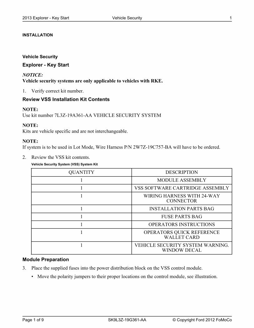
2. Review the VSS kit contents.Vehicle Security System (VSS) System Kit
QUANTITY DESCRIPTION1 MODULE ASSEMBLY1 VSS SOFTWARE CARTRIDGE ASSEMBLY1 WIRING HARNESS WITH 24-WAY
CONNECTOR1 INSTALLATION PARTS BAG1 FUSE PARTS BAG1 OPERATORS INSTRUCTIONS1 OPERATORS QUICK REFERENCE
WALLET CARD1 VEHICLE SECURITY SYSTEM WARNING.
WINDOW DECAL
Module Preparation3. Place the supplied fuses into the power distribution block on the VSS control module.
• Move the polarity jumpers to their proper locations on the control module, see illustration.
2013 Explorer - Key Start Vehicle Security 1
Page 1 of 9 SK9L3Z-19G361-AA © Copyright Ford 2012 FoMoCo

4. Place the software cartridge onto the control module.
INSTALLATION (Continued)2013 Explorer - Key Start Vehicle Security 2
Page 2 of 9 SK9L3Z-19G361-AA © Copyright Ford 2012 FoMoCo
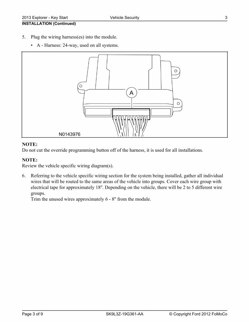
NOTE: Do not cut the override programming button off of the harness, it is used for all installations.
NOTE: Review the vehicle specific wiring diagram(s).
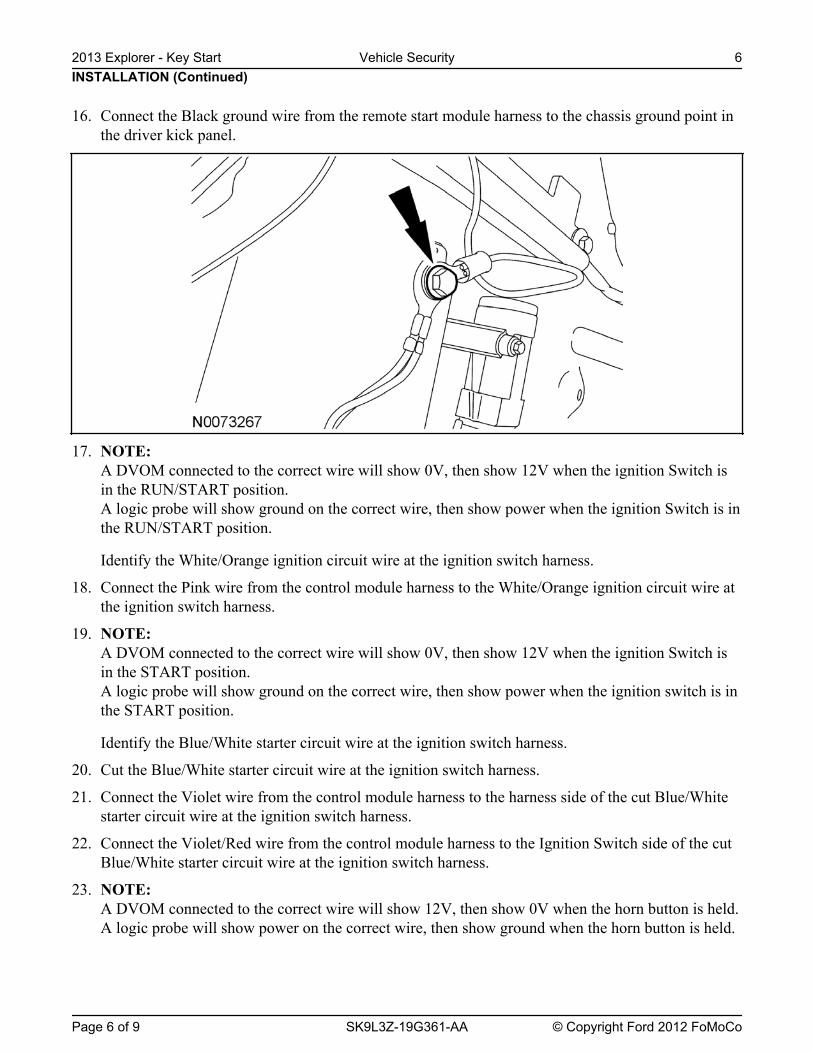
6. Referring to the vehicle specific wiring section for the system being installed, gather all individualwires that will be routed to the same areas of the vehicle into groups. Cover each wire group withelectrical tape for approximately 18''. Depending on the vehicle, there will be 2 to 5 different wiregroups.Trim the unused wires approximately 6 - 8'' from the module.
INSTALLATION (Continued)2013 Explorer - Key Start Vehicle Security 3
Page 3 of 9 SK9L3Z-19G361-AA © Copyright Ford 2012 FoMoCo
5. Plug the wiring harness(es) into the module.
• A - Harness: 24-way, used on all systems.
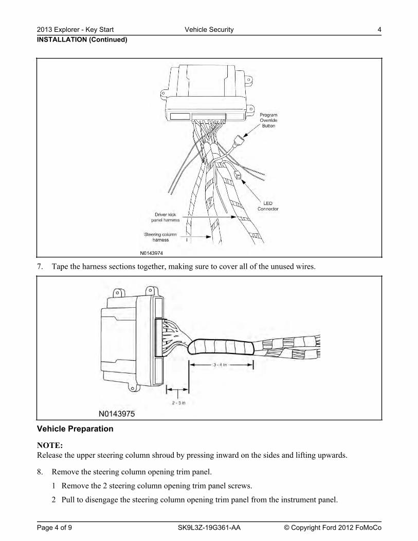
7. Tape the harness sections together, making sure to cover all of the unused wires.
Vehicle Preparation
NOTE: Release the upper steering column shroud by pressing inward on the sides and lifting upwards.
8. Remove the steering column opening trim panel.
1 Remove the 2 steering column opening trim panel screws.
2 Pull to disengage the steering column opening trim panel from the instrument panel.
INSTALLATION (Continued)2013 Explorer - Key Start Vehicle Security 4
Page 4 of 9 SK9L3Z-19G361-AA © Copyright Ford 2012 FoMoCo

9. Remove the steering column shrouds.
1 Remove the 3 lower shroud retainers.
2 Detach and remove the lower shroud from the upper shroud.
3 Detach the instrument panel cluster opening trim from the upper shroud.
4 Remove the upper shroud.
10. Remove the driver side front door scuff plate.
Install the Control Module and Harness Assembly11. Place the control module and harness assembly in the vehicle.
Install LED12. Connect the LED harness to the RMST module harness LED connector.
13. Route the LED harness through the instrument panel to the driver side of the vehicle.Keep the following points in mind when routing or positioning the LED for mounting:
• Have at least 3/4" clearance behind any trim panel for the wiring harness to be routed.
• The LED should be clearly visible from the driver's side window when mounted.
• Do not mount the LED on trim panels that cover air bags.
14. Mount the LED at an appropriate location on the driver's side of the vehicle using the guidelineslisted above.
• Drill a 9/32" hole into the selected location, for the LED to mount in.
15. Secure the LED wire harness with tie-straps.
Identify Circuit Wires For Connections
NOTE: Review the vehicle specific wiring diagram(s).NOTE:
INSTALLATION (Continued)
Review proper wire splicing techniques.
2013 Explorer - Key Start Vehicle Security 5
Page 5 of 9 SK9L3Z-19G361-AA © Copyright Ford 2012 FoMoCo
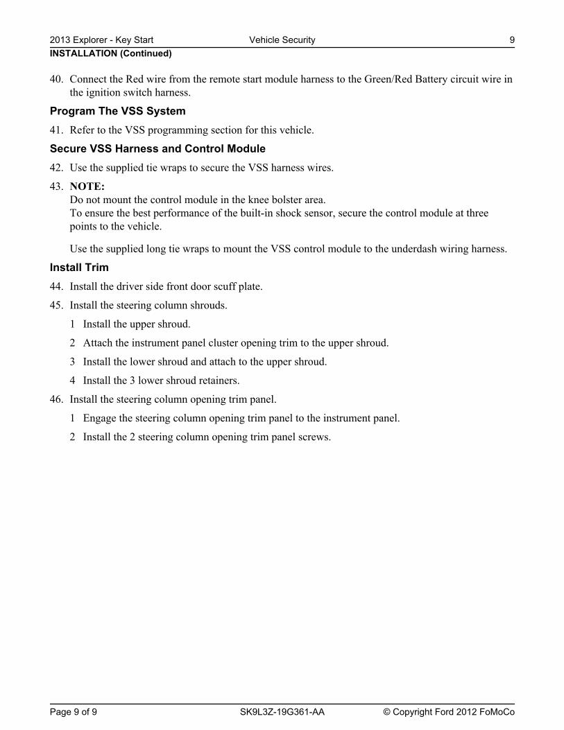
16. Connect the Black ground wire from the remote start module harness to the chassis ground point inthe driver kick panel.
17. NOTE: A DVOM connected to the correct wire will show 0V, then show 12V when the ignition Switch isin the RUN/START position.A logic probe will show ground on the correct wire, then show power when the ignition Switch is inthe RUN/START position.
Identify the White/Orange ignition circuit wire at the ignition switch harness.
18. Connect the Pink wire from the control module harness to the White/Orange ignition circuit wire atthe ignition switch harness.
19. NOTE: A DVOM connected to the correct wire will show 0V, then show 12V when the ignition Switch isin the START position.A logic probe will show ground on the correct wire, then show power when the ignition switch is inthe START position.
Identify the Blue/White starter circuit wire at the ignition switch harness.
20. Cut the Blue/White starter circuit wire at the ignition switch harness.
21. Connect the Violet wire from the control module harness to the harness side of the cut Blue/Whitestarter circuit wire at the ignition switch harness.
22. Connect the Violet/Red wire from the control module harness to the Ignition Switch side of the cutBlue/White starter circuit wire at the ignition switch harness.
23. NOTE: A DVOM connected to the correct wire will show 12V, then show 0V when the horn button is held.A logic probe will show power on the correct wire, then show ground when the horn button is held.
INSTALLATION (Continued)2013 Explorer - Key Start Vehicle Security 6
Page 6 of 9 SK9L3Z-19G361-AA © Copyright Ford 2012 FoMoCo

Wire is located inside wire loom running to black connector but does not terminate. Wire can befound 4'' from connector on the side heading toward the rear of the vehicle in a looped fashionunderneath bright green tape.
Identify the Violet/Green horn circuit wire at the steering column harness.
24. Connect the Brown/Black wire from the control module harness to the Violet/Green horn circuitwire at the steering column harness.
25. NOTE: A DVOM connected to the correct wire will show 12V, when the headlight switch is in the parklamp position, then show 0V when the headlight switch is OFF.A logic probe will show power on the correct wire when the headlight switch is in the park lampposition, then show ground when the headlight switch is OFF.
Identify the Yellow/Blue parking light on circuit wire at the driver kick panel.
26. Connect the White wire from the control module harness to the Yellow/Blue parking light circuit atthe driver kick panel.
27. NOTE: A DVOM connected to the correct wire will show 12V with the vehicle door(s) open and the domelight ON, then show 0V with the vehicle door(s) closed and the dome light OFF.
NOTE: A logic probe connected to the correct wire will show power with the vehicle door(s) open and thedome light ON, then show ground with the vehicle door(s) closed and the dome light OFF.
NOTE: Be sure that the dome light has timed out and is OFF before performing the door closed test.Be sure that the dome lamp is illuminated before performing the door open test.
Identify the Gray/Violet dome light circuit wire at BCM connector C2280A Pin 1.
28. Connect the Green/Violet wire from the control module harness to the Gray/Violet dome lightcircuit at BCM connector C2280A Pin 1.
29. NOTE: A DVOM connected to the correct wire will show 0V, then show 12V when the door lock switch ispressed.A logic probe will show ground on the correct wire, then show power when the door lock switch ispressed.
Identify the Gray/Brown power door lock motor circuit wire at the driver kick panel.
30. Connect the White/Blue wire from the control module harness to the Gray/Brown power door lockmotor circuit at the driver kick panel.
31. NOTE: Connect only if system will be used in Lot Mode.
INSTALLATION (Continued)
NOTE:
2013 Explorer - Key Start Vehicle Security 7
Page 7 of 9 SK9L3Z-19G361-AA © Copyright Ford 2012 FoMoCo

A DVOM connected to the correct wire will show 12V, then show 0V when the door lock switch ispressed.A logic probe will show open on the correct wire, then show ground when the door lock switch ispressed.
Identify the Blue/Green power door lock circuit wire at the driver kick panel.
32. Connect the Blue wire from the control module harness to the Blue/Green power door lock circuit atthe driver kick panel.
33. NOTE: Connect only if system will be used in Lot Mode.
NOTE: A DVOM connected to the correct wire will show 12V, then show 0V while the door unlock switchis pressed.A logic probe will show open on the correct wire, then show ground while the door unlock switch ispressed.
Identify the Yellow/Violet door unlock circuit wire at the driver kick panel.
34. Connect the Green wire from the control module harness to the Yellow/Violet door unlock circuitwire at the driver kick panel.
35. NOTE: A DVOM connected to the correct wire will show 0V, then show 12V while the door unlock switchis pressed.A logic probe will show ground on the correct wire, then show power while the door unlock switchis pressed.
Identify the Violet/Gray all door unlock motor circuit wire at the driver kick panel.
36. Connect the Light Green wire from the control module harness to the Violet/Gray all door unlockmotor circuit wire at the driver kick panel.
37. NOTE: A DVOM connected to the correct wire will show 0V, then show 12V when the remote unlockswitch is pressed.A logic probe will show ground on the correct wire, then show power when the remote unlockswitch is pressed.
Identify the Blue/Green driver door unlock motor circuit wire at the driver kick panel.
38. Connect the Brown wire from the control module harness to the Blue/Green driver door unlockmotor circuit wire at the driver kick panel.
Power Connection39. NOTE:
A DVOM connected to the correct wire will show 12V with the key in any position.A logic probe will show power on the correct wire with the key in any position.
Identify the Green/Red Battery circuit wire in the ignition switch harness.
INSTALLATION (Continued)
NOTE:
2013 Explorer - Key Start Vehicle Security 8
Page 8 of 9 SK9L3Z-19G361-AA © Copyright Ford 2012 FoMoCo
40. Connect the Red wire from the remote start module harness to the Green/Red Battery circuit wire inthe ignition switch harness.
Program The VSS System41. Refer to the VSS programming section for this vehicle.
Secure VSS Harness and Control Module42. Use the supplied tie wraps to secure the VSS harness wires.
43. NOTE: Do not mount the control module in the knee bolster area.To ensure the best performance of the built-in shock sensor, secure the control module at threepoints to the vehicle.
Use the supplied long tie wraps to mount the VSS control module to the underdash wiring harness.
Install Trim44. Install the driver side front door scuff plate.
45. Install the steering column shrouds.
1 Install the upper shroud.
2 Attach the instrument panel cluster opening trim to the upper shroud.
3 Install the lower shroud and attach to the upper shroud.
4 Install the 3 lower shroud retainers.
46. Install the steering column opening trim panel.
1 Engage the steering column opening trim panel to the instrument panel.
2 Install the 2 steering column opening trim panel screws.
INSTALLATION (Continued)2013 Explorer - Key Start Vehicle Security 9
Page 9 of 9 SK9L3Z-19G361-AA © Copyright Ford 2012 FoMoCo
GENERAL PROCEDURES
5. Press and hold the VSS override button for atleast 10 seconds.
After 10 seconds the horn with honk 3 times,indicating the system is now in the learn mode.
6. Press and release the override button. The hornwill honk 4 times indicating the system hasentered the first program bank.
If not please check the following:
• All door and dome light circuit wire solderconnections.
• The key is in the RUN position.
• The software cartridge is firmly seated inthe VSS module.
• The VSS harness connections are firmlyseated in the VSS module.
NOTE: If you require additional assistance: CALL1-800-FORD KEY.
7. Press and release the Lock button on the trimswitch 3 times.
The horn will honk 3 times indicating thesystem has entered the option 3 of the firstprogram bank.
NOTICE: To turn the LED on or off, press andimmediately release Unlock button on the trimswitch.
8. The LED must be ON for option 3. If the LEDis illuminated no action is required. If the LEDis not illuminated press the Unlock button andverify the LED illuminates.
NOTE: When programming the VSS module, if theLock button is held for more than 3 seconds, thehorn will honk 4 times indicating the systemreturned to the factory default settings. If thisoccurs, return to step 1 of the programming sectionto reprogram the remote start module.
9. Press and release the Lock button on the trimswitch.
The horn will honk 4 times indication thesystem has entered the option 4 of the firstprogram bank.
Programming
Programming the Module
1. NOTE: Make sure that the hood and doors areclosed before proceeding.
NOTE: The LED on the VSS harness must bevisible to complete module programming.
NOTE: The VSS override button must beaccessible.
Programming Options: EnteringProgramming Mode
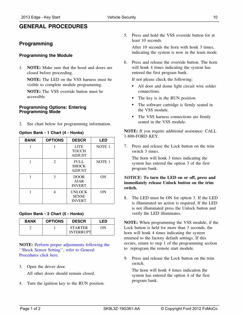
2. See chart below for programming information.
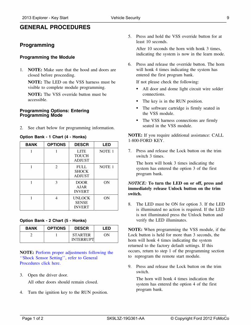
Option Bank - 1 Chart (4 - Honks)
BANK OPTIONS DESCR
LITETOUCHADJUST
FULLSHOCKADJUST
DOORAJAR
INVERT
UNLOCKSENSE
INVERT
LED
NOTE 1
NOTE 1
ON
ON
1 1
1 2
1 3
1 4
Option Bank - 2 Chart (5 - Honks)
BANK OPTIONS DESCR LED
2 1 STARTER ONINTERRUPT
NOTE: Perform proper adjustments following the‘‘Shock Sensor Setting’’, refer to GeneralProcedures click here.
3. Open the driver door.
All other doors should remain closed.
4. Turn the ignition key to the RUN position.
2013 Explorer - Key Start Vehicle Security 9
Page 1 of 2 SK9L3Z-19G361-AA © Copyright Ford 2012 FoMoCo
GENERAL PROCEDURES (Continued)
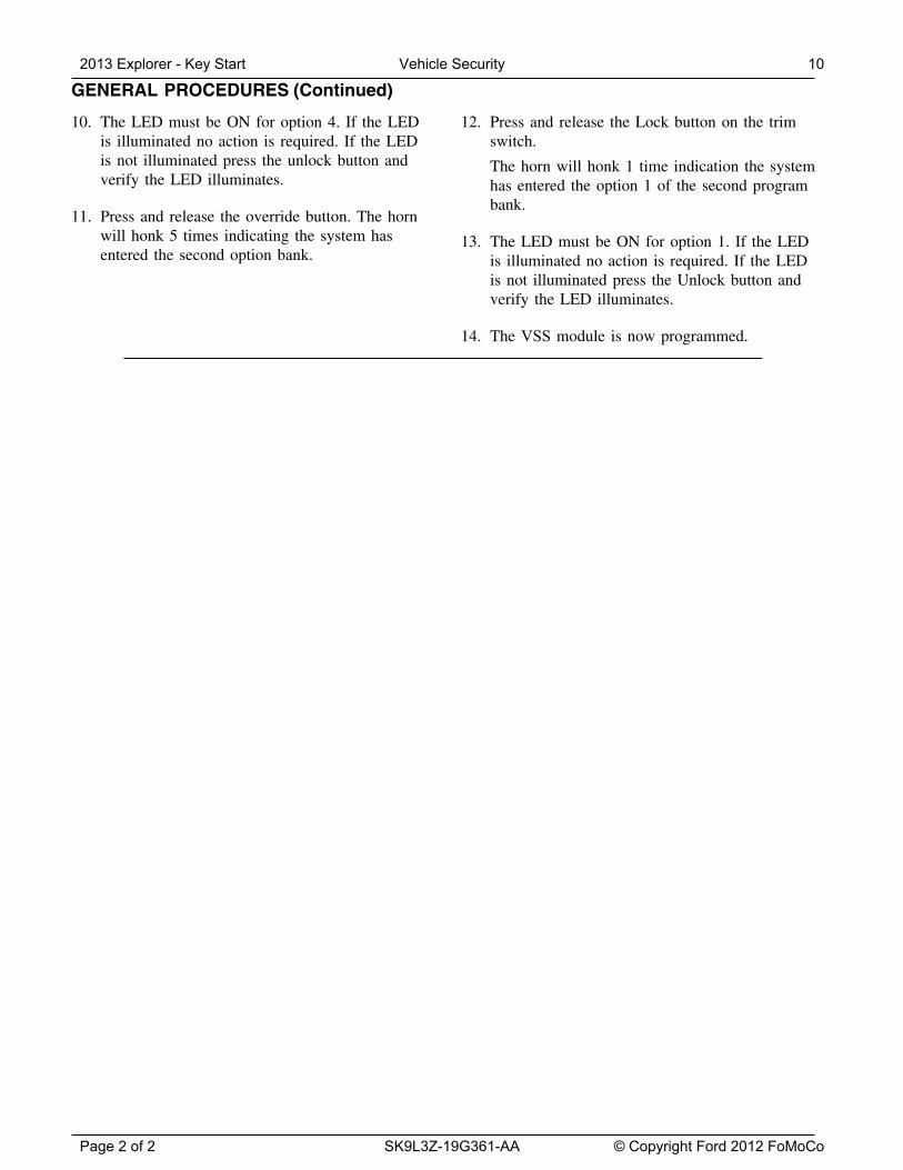
10. The LED must be ON for option 4. If the LEDis illuminated no action is required. If the LEDis not illuminated press the unlock button andverify the LED illuminates.
11. Press and release the override button. The hornwill honk 5 times indicating the system hasentered the second option bank.
12. Press and release the Lock button on the trimswitch.
The horn will honk 1 time indication the systemhas entered the option 1 of the second programbank.
13. The LED must be ON for option 1. If the LEDis illuminated no action is required. If the LEDis not illuminated press the Unlock button andverify the LED illuminates.
14. The VSS module is now programmed.
2013 Explorer - Key Start Vehicle Security 10
Page 2 of 2 SK9L3Z-19G361-AA © Copyright Ford 2012 FoMoCo
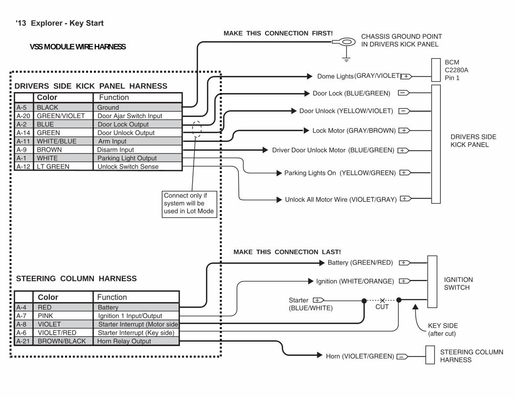
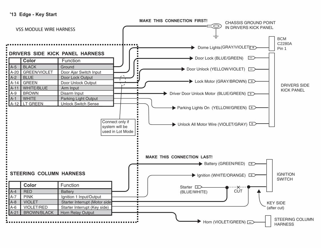
'13 Explorer - Key Start
Color FunctionA-5 BLACK GroundA-20 GREEN/VIOLET Door Ajar Switch InputA-2 BLUE Door Lock Output A-14 GREEN Door Unlock OutputA-11 WHITE/BLUE Arm Input A-9 BROWN Disarm InputA-1 WHITE Parking Light OutputA-12 LT GREEN Unlock Switch Sense
DRIVERS SIDE KICK PANEL HARNESS
CHASSIS GROUND POINTIN DRIVERS KICK PANEL
MAKE THIS CONNECTION FIRST!
DRIVERS SIDEKICK PANEL
Dome Lights(GRAY/VIOLET) +
+
+
Door Lock (BLUE/GREEN)
Door Unlock (YELLOW/VIOLET)
Lock Motor (GRAY/BROWN)
Driver Door Unlock Motor (BLUE/GREEN)
+Unlock All Motor Wire (VIOLET/GRAY)
Color FunctionA-4 RED BatteryA-7 PINK Ignition 1 Input/OutputA-8 VIOLET Starter Interrupt (Motor side)A-6 VIOLET/RED Starter Interrupt (Key side)A-21 BROWN/BLACK Horn Relay Output
IGNITIONSWITCH
Battery (GREEN/RED)
Starter(BLUE/WHITE)
Ignition (WHITE/ORANGE)
STEERING COLUMNHARNESSHorn (VIOLET/GREEN)
STEERING COLUMN HARNESS
+
+
+
CUT
KEY SIDE(after cut)
MAKE THIS CONNECTION LAST!
Connect only if system will be used in Lot Mode
BCM C2280A Pin 1
+Parking Lights On (YELLOW/GREEN)
VSS MODULE WIRE HARNESS

2013 Edge - Key Start Vehicle Security
Manual Table of Contents
VSS SYSTEM INSTALLATIONCONTENTS
INSTALLATIONVSS
GENERAL PROCEDURES Proper Splicing Techniques Programming Shock Sensor Setting WIRING DIAGRAMS Vehicle Specific Wiring Diagrams
Contents SK9L3Z-19A361-AA © Copyright Ford 2012 FoMoCo
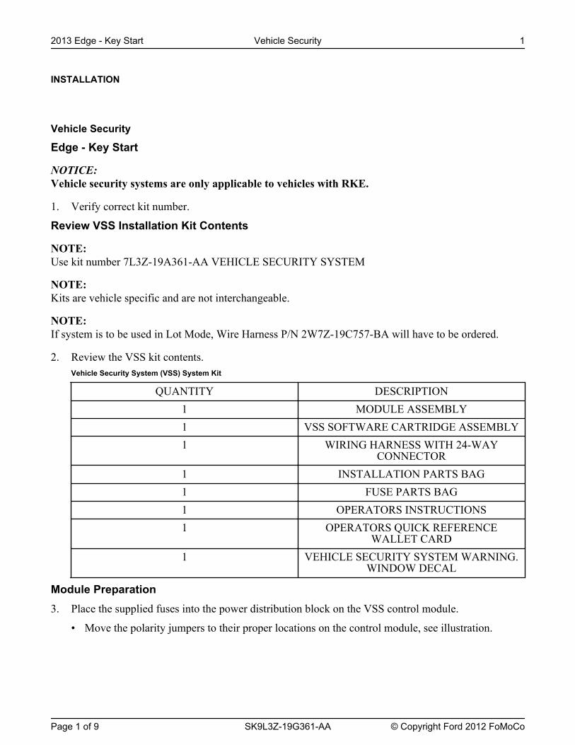
INSTALLATION
Vehicle Security
Edge - Key Start
NOTICE: Vehicle security systems are only applicable to vehicles with RKE.
1. Verify correct kit number.
Review VSS Installation Kit Contents
NOTE: Use kit number 7L3Z-19A361-AA VEHICLE SECURITY SYSTEM
NOTE: Kits are vehicle specific and are not interchangeable.
NOTE: If system is to be used in Lot Mode, Wire Harness P/N 2W7Z-19C757-BA will have to be ordered.
2. Review the VSS kit contents.Vehicle Security System (VSS) System Kit
QUANTITY DESCRIPTION1 MODULE ASSEMBLY1 VSS SOFTWARE CARTRIDGE ASSEMBLY1 WIRING HARNESS WITH 24-WAY
CONNECTOR1 INSTALLATION PARTS BAG1 FUSE PARTS BAG1 OPERATORS INSTRUCTIONS1 OPERATORS QUICK REFERENCE
WALLET CARD1 VEHICLE SECURITY SYSTEM WARNING.
WINDOW DECAL
Module Preparation3. Place the supplied fuses into the power distribution block on the VSS control module.
• Move the polarity jumpers to their proper locations on the control module, see illustration.
2013 Edge - Key Start Vehicle Security 1
Page 1 of 9 SK9L3Z-19G361-AA © Copyright Ford 2012 FoMoCo
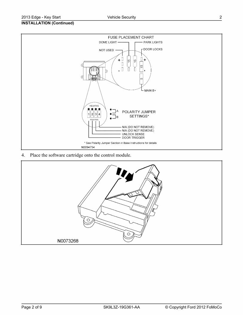
4. Place the software cartridge onto the control module.
INSTALLATION (Continued)2013 Edge - Key Start Vehicle Security 2
Page 2 of 9 SK9L3Z-19G361-AA © Copyright Ford 2012 FoMoCo
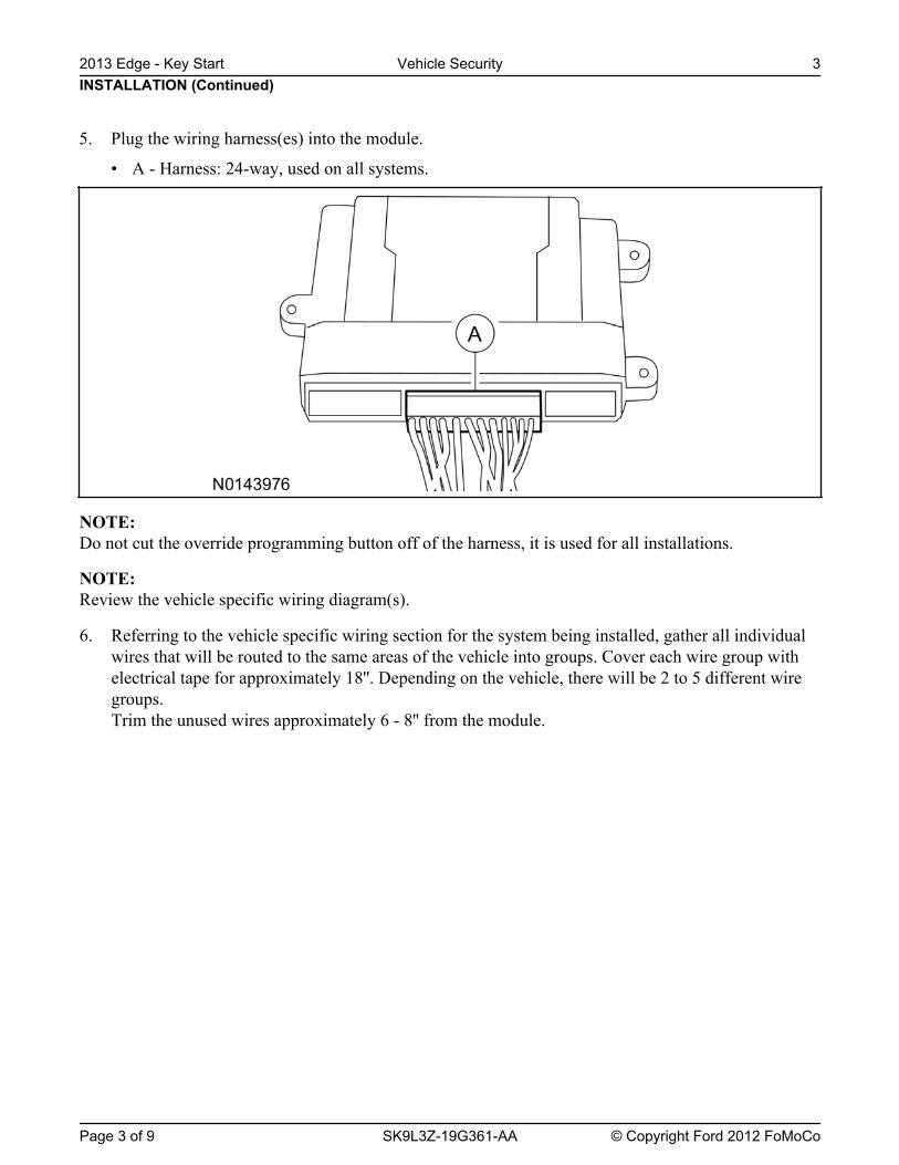
NOTE: Do not cut the override programming button off of the harness, it is used for all installations.
NOTE: Review the vehicle specific wiring diagram(s).
6. Referring to the vehicle specific wiring section for the system being installed, gather all individualwires that will be routed to the same areas of the vehicle into groups. Cover each wire group withelectrical tape for approximately 18''. Depending on the vehicle, there will be 2 to 5 different wiregroups.Trim the unused wires approximately 6 - 8'' from the module.
INSTALLATION (Continued)2013 Edge - Key Start Vehicle Security 3
Page 3 of 9 SK9L3Z-19G361-AA © Copyright Ford 2012 FoMoCo
5. Plug the wiring harness(es) into the module.
• A - Harness: 24-way, used on all systems.
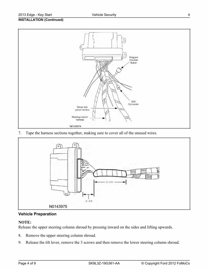
7. Tape the harness sections together, making sure to cover all of the unused wires.
Vehicle Preparation
NOTE: Release the upper steering column shroud by pressing inward on the sides and lifting upwards.
8. Remove the upper steering column shroud.
9. Release the tilt lever, remove the 3 screws and then remove the lower steering column shroud.
INSTALLATION (Continued)2013 Edge - Key Start Vehicle Security 4
Page 4 of 9 SK9L3Z-19G361-AA © Copyright Ford 2012 FoMoCo
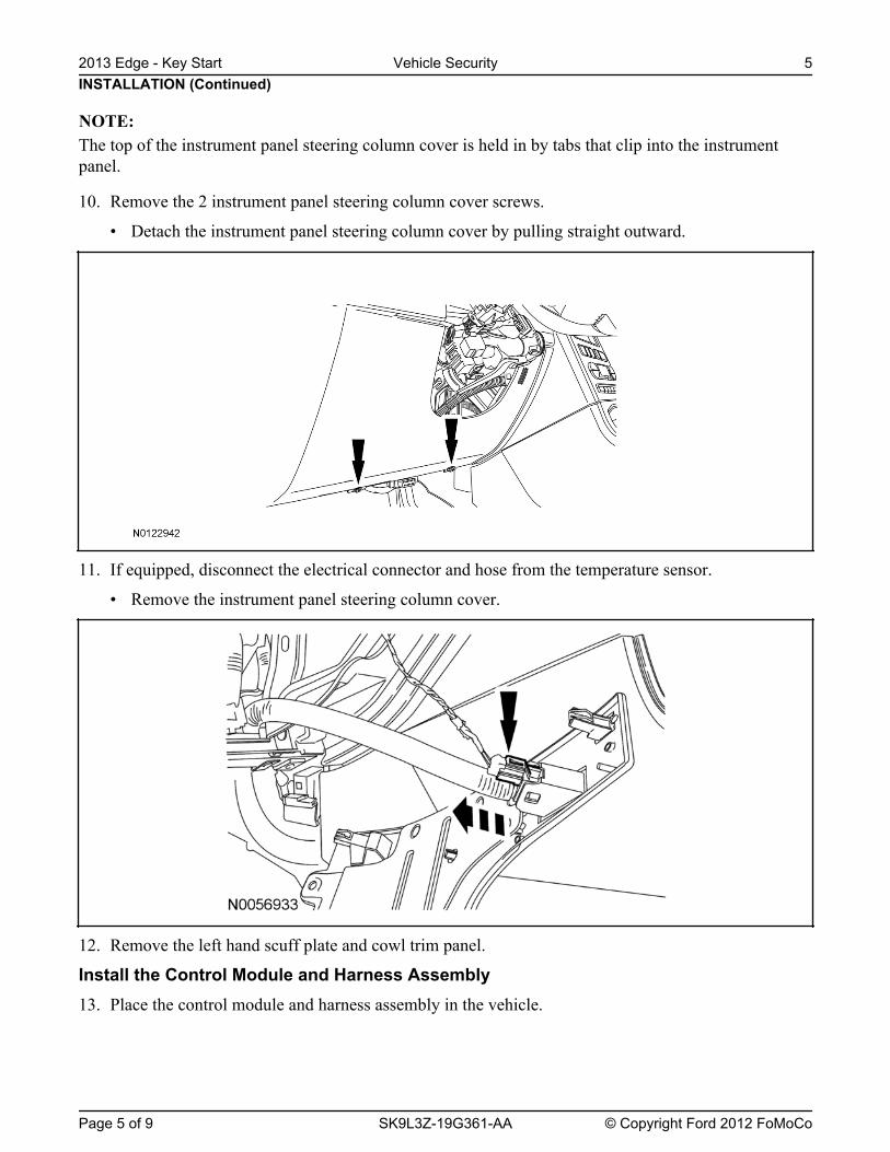
The top of the instrument panel steering column cover is held in by tabs that clip into the instrumentpanel.
10. Remove the 2 instrument panel steering column cover screws.
• Detach the instrument panel steering column cover by pulling straight outward.
11. If equipped, disconnect the electrical connector and hose from the temperature sensor.
• Remove the instrument panel steering column cover.
12. Remove the left hand scuff plate and cowl trim panel.
Install the Control Module and Harness Assembly13. Place the control module and harness assembly in the vehicle.
INSTALLATION (Continued)
NOTE:
2013 Edge - Key Start Vehicle Security 5
Page 5 of 9 SK9L3Z-19G361-AA © Copyright Ford 2012 FoMoCo
Identify Circuit Wires For Connections
NOTE: Review the vehicle specific wiring diagram(s).
NOTE: Review proper wire splicing techniques.
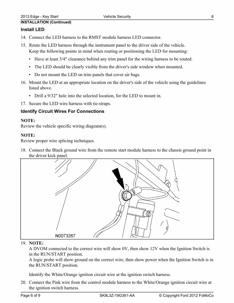
18. Connect the Black ground wire from the remote start module harness to the chassis ground point inthe driver kick panel.
19. NOTE: A DVOM connected to the correct wire will show 0V, then show 12V when the Ignition Switch isin the RUN/START position.A logic probe will show ground on the correct wire, then show power when the Ignition Switch is inthe RUN/START position.
Identify the White/Orange ignition circuit wire at the ignition switch harness.
20. Connect the Pink wire from the control module harness to the White/Orange ignition circuit wire atthe ignition switch harness.
INSTALLATION (Continued)
Install LED14. Connect the LED harness to the RMST module harness LED connector.
15. Route the LED harness through the instrument panel to the driver side of the vehicle.Keep the following points in mind when routing or positioning the LED for mounting:
• Have at least 3/4" clearance behind any trim panel for the wiring harness to be routed.
• The LED should be clearly visible from the driver's side window when mounted.
• Do not mount the LED on trim panels that cover air bags.
16. Mount the LED at an appropriate location on the driver's side of the vehicle using the guidelineslisted above.
• Drill a 9/32" hole into the selected location, for the LED to mount in.
17. Secure the LED wire harness with tie-straps.
2013 Edge - Key Start Vehicle Security 6
Page 6 of 9 SK9L3Z-19G361-AA © Copyright Ford 2012 FoMoCo

A DVOM connected to the correct wire will show 0V, then show 12V when the Ignition Switch isin the START position.A logic probe will show ground on the correct wire, then show power when the Ignition Switch is inthe START position.
Identify the Blue/White starter circuit wire at the ignition switch harness.
22. Cut the Blue/White starter circuit wire at the ignition switch harness.
23. Connect the Violet wire from the control module harness to the harness side of the cut Blue/Whitestarter circuit wire at the ignition switch harness.
24. Connect the Violet/Red wire from the control module harness to the Ignition Switch side of the cutBlue/White starter circuit wire at the ignition switch harness.
25. NOTE: A DVOM connected to the correct wire will show 12V, then show 0V when the horn button is held.A logic probe will show power on the correct wire, then show ground when the horn button is held.
NOTE: Wire is located inside wire loom running to black connector but does not terminate. Wire can befound 4'' from connector on the side heading toward the rear of the vehicle in a looped fashionunderneath bright green tape.
Identify the Violet/Green horn circuit wire at the steering column harness.
26. Connect the Brown/Black wire from the control module harness to the Violet/Green horn circuitwire at the steering column harness.
27. NOTE: A DVOM connected to the correct wire will show 12V, when the Headlight Switch is in the parklamp position, then show 0V when the Headlight Switch is OFF.A logic probe will show power on the correct wire when the Headlight Switch is in the park lampposition, then show ground when the Headlight Switch is OFF.
Identify the Yellow/Green parking light on circuit wire at the driver kick panel.
28. Connect the White wire from the control module harness to the Yellow/Green parking light circuitat the driver kick panel.
29. NOTE: A DVOM connected to the correct wire will show 12V with the vehicle door(s) open and the domelight ON, then show 0V with the vehicle door(s) closed and the dome light OFF.
NOTE: A logic probe connected to the correct wire will show power with the vehicle door(s) open and thedome light ON, then show ground with the vehicle door(s) closed and the dome light OFF.
NOTE: Be sure that the dome light has timed out and is OFF before performing the door closed test.Be sure that the dome lamp is illuminated before performing the door open test.
Identify the Gray/Violet dome light circuit wire at BCM connector C2280A Pin 1.
INSTALLATION (Continued)
21. NOTE:
2013 Edge - Key Start Vehicle Security 7
Page 7 of 9 SK9L3Z-19G361-AA © Copyright Ford 2012 FoMoCo

30. Connect the Green/Violet wire from the control module harness to the Gray/Violet dome lightcircuit at BCM connector C2280A Pin 1.
31. NOTE: A DVOM connected to the correct wire will show 0V, then show 12V when the door lock switch ispressed.A logic probe will show ground on the correct wire, then show power when the door lock switch ispressed.
Identify the Gray/Brown power door lock motor circuit wire at the driver kick panel.
32. Connect the White/Blue wire from the control module harness to the Gray/Brown power door lockmotor circuit at the driver kick panel.
33. NOTE: Connect only if system will be used in Lot Mode.
NOTE: A DVOM connected to the correct wire will show 12V, then show 0V when the door lock switch ispressed.A logic probe will show open on the correct wire, then show ground when the door lock switch ispressed.
Identify the Blue/Green power door lock circuit wire at the driver kick panel.
34. Connect the Blue wire from the control module harness to the Blue/Green power door lock circuit atthe driver kick panel.
35. NOTE: Connect only if system will be used in Lot Mode.
NOTE: A DVOM connected to the correct wire will show 12V, then show 0V while the door unlock switchis pressed.A logic probe will show open on the correct wire, then show ground while the door unlock switch ispressed.
Identify the Yellow/Violet door unlock circuit wire at the driver kick panel.
36. Connect the Green wire from the control module harness to the Yellow/Violet door unlock circuitwire at the driver kick panel.
37. NOTE: A DVOM connected to the correct wire will show 0V, then show 12V while the door unlock switchis pressed.A logic probe will show ground on the correct wire, then show power while the door unlock switchis pressed.
Identify the Violet/Gray all door unlock motor circuit wire at the driver kick panel.
38. Connect the Light Green wire from the control module harness to the Violet/Gray all door unlockmotor circuit wire at the driver kick panel.
INSTALLATION (Continued)2013 Edge - Key Start Vehicle Security 8
Page 8 of 9 SK9L3Z-19G361-AA © Copyright Ford 2012 FoMoCo

A DVOM connected to the correct wire will show 0V, then show 12V when the remote unlockswitch is pressed.A logic probe will show ground on the correct wire, then show power when the remote unlockswitch is pressed.
Identify the Blue/Green driver door unlock motor circuit wire at the driver kick panel.
40. Connect the Brown wire from the control module harness to the Blue/Green driver door unlockmotor circuit wire at the driver kick panel.
Power Connection41. NOTE:
A DVOM connected to the correct wire will show 12V with the key in any position.A logic probe will show power on the correct wire with the key in any position.
Identify the Blue/Red Battery circuit wire in the ignition switch harness.
42. Connect the Red wire from the remote start module harness to the Blue/Red Battery circuit wire inthe ignition switch harness.
Program The VSS System43. Refer to the VSS programming section for this vehicle.
Secure VSS Harness and Control Module44. Use the supplied tie wraps to secure the VSS harness wires.
45. NOTE: Do not mount the control module in the knee bolster area.To ensure the best performance of the built-in shock sensor, secure the control module at threepoints to the vehicle.
Use the supplied long tie wraps to mount the VSS control module to the underdash wiring harness.
Install Trim46. Install the left hand scuff plate and cowl trim panel.
47. If equipped, connect the electrical connector and hose to the temperature sensor.
• Install the instrument panel steering column cover.
48. Install the 2 instrument panel steering column cover screws.
• Attach the instrument panel steering column cover by pushing straight inward.
49. Install the lower steering column shroud, install the 3 screws.
50. Install the upper steering column shroud.
INSTALLATION (Continued)
39. NOTE:
2013 Edge - Key Start Vehicle Security 9
Page 9 of 9 SK9L3Z-19G361-AA © Copyright Ford 2012 FoMoCo
GENERAL PROCEDURES
5. Press and hold the VSS override button for atleast 10 seconds.
ProgrammingAfter 10 seconds the horn with honk 3 times,indicating the system is now in the learn mode.
Programming the Module
6. Press and release the override button. The hornwill honk 4 times indicating the system has1. NOTE: Make sure that the hood and doors areentered the first program bank.closed before proceeding.
If not please check the following:NOTE: The LED on the VSS harness must bevisible to complete module programming. • All door and dome light circuit wire solder
connections.NOTE: The VSS override button must beaccessible. • The key is in the RUN position.
• The software cartridge is firmly seated inProgramming Options: Enteringthe VSS module.Programming Mode
• The VSS harness connections are firmlyseated in the VSS module.2. See chart below for programming information.
NOTE: If you require additional assistance: CALLOption Bank - 1 Chart (4 - Honks)1-800-FORD KEY.
BANK OPTIONS DESCR LED
7. Press and release the Lock button on the trim1 1 LITE NOTE 1TOUCH switch 3 times.ADJUST
The horn will honk 3 times indicating the1 2 FULL NOTE 1 system has entered the option 3 of the first
SHOCK program bank.ADJUST
1 3 DOOR ON NOTICE: To turn the LED on or off, press andAJAR immediately release Unlock button on the trim
INVERT switch.1 4 UNLOCK ON
SENSE 8. The LED must be ON for option 3. If the LEDINVERT is illuminated no action is required. If the LED
is not illuminated press the Unlock button andverify the LED illuminates.Option Bank - 2 Chart (5 - Honks)
BANK OPTIONS DESCR LED NOTE: When programming the VSS module, if the2 1 STARTER ON Lock button is held for more than 3 seconds, the
INTERRUPT horn will honk 4 times indicating the systemreturned to the factory default settings. If thisoccurs, return to step 1 of the programming sectionNOTE: Perform proper adjustments following theto reprogram the remote start module.‘‘Shock Sensor Setting’’, refer to General
Procedures click here.9. Press and release the Lock button on the trim
switch.3. Open the driver door.
The horn will honk 4 times indication theAll other doors should remain closed. system has entered the option 4 of the first
program bank.4. Turn the ignition key to the RUN position.
2013 Edge - Key Start Vehicle Security 10
Page 1 of 2 SK9L3Z-19G361-AA © Copyright Ford 2012 FoMoCo

GENERAL PROCEDURES (Continued)
10. The LED must be ON for option 4. If the LED 12. Press and release the Lock button on the trimis illuminated no action is required. If the LED switch.is not illuminated press the unlock button and The horn will honk 1 time indication the systemverify the LED illuminates. has entered the option 1 of the second program
bank.11. Press and release the override button. The horn
will honk 5 times indicating the system has 13. The LED must be ON for option 1. If the LEDentered the second option bank. is illuminated no action is required. If the LED
is not illuminated press the Unlock button andverify the LED illuminates.
14. The VSS module is now programmed.
2013 Edge - Key Start Vehicle Security 11
Page 2 of 2 SK9L3Z-19G361-AA © Copyright Ford 2012 FoMoCo
'13 Edge - Key Start
Color FunctionA-5 BLACK GroundA-20 GREEN/VIOLET Door Ajar Switch InputA-2 BLUE Door Lock Output A-14 GREEN Door Unlock OutputA-11 WHITE/BLUE Arm Input A-9 BROWN Disarm InputA-1 WHITE Parking Light OutputA-12 LT GREEN Unlock Switch Sense
DRIVERS SIDE KICK PANEL HARNESS
CHASSIS GROUND POINTIN DRIVERS KICK PANEL
MAKE THIS CONNECTION FIRST!
DRIVERS SIDEKICK PANEL
Dome Lights(GRAY/VIOLET) +
+
+
Door Lock (BLUE/GREEN)
Door Unlock (YELLOW/VIOLET)
Lock Motor (GRAY/BROWN)
Driver Door Unlock Motor (BLUE/GREEN)
+Unlock All Motor Wire (VIOLET/GRAY)
Color FunctionA-4 RED BatteryA-7 PINK Ignition 1 Input/OutputA-8 VIOLET Starter Interrupt (Motor side)A-6 VIOLET/RED Starter Interrupt (Key side)A-21 BROWN/BLACK Horn Relay Output
IGNITIONSWITCH
Battery (GREEN/RED)
Starter(BLUE/WHITE)
Ignition (WHITE/ORANGE)
STEERING COLUMNHARNESSHorn (VIOLET/GREEN)
STEERING COLUMN HARNESS
+
+
+
CUT
KEY SIDE(after cut)
MAKE THIS CONNECTION LAST!
Connect only if system will be used in Lot Mode
BCMC2280APin 1
+Parking Lights On (YELLOW/GREEN)
VSS MODULE WIRE HARNESS
Manual Table of Contents
Vehicle Security SystemCONTENTS
INSTALLATIONVehicle Security System
GENERAL PROCEDURES Proper Splicing Techniques Programming Shock Sensor Setting WIRING DIAGRAMS Vehicle Specific Wiring Diagrams
2013 Flex - Key Start Vehicle Security
Contents SK9L3Z-19G361-AA © Copyright Ford 2012 FoMoCo
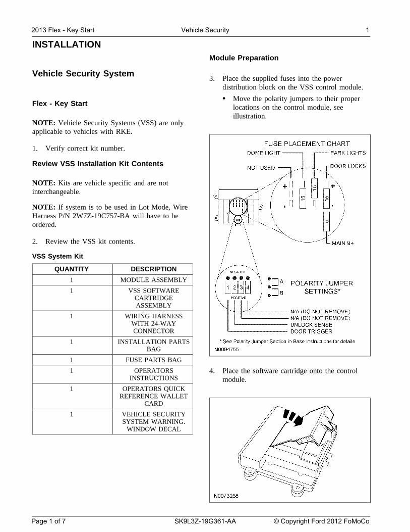
INSTALLATIONModule Preparation
Vehicle Security System 3. Place the supplied fuses into the power
distribution block on the VSS control module.
• Move the polarity jumpers to their properFlex - Key Start locations on the control module, see
illustration.NOTE: Vehicle Security Systems (VSS) are onlyapplicable to vehicles with RKE.
1. Verify correct kit number.
Review VSS Installation Kit Contents
NOTE: Kits are vehicle specific and are notinterchangeable.
NOTE: If system is to be used in Lot Mode, WireHarness P/N 2W7Z-19C757-BA will have to beordered.
2. Review the VSS kit contents.
VSS System Kit
QUANTITY DESCRIPTION
1 MODULE ASSEMBLY
1 VSS SOFTWARECARTRIDGEASSEMBLY
1 WIRING HARNESSWITH 24-WAYCONNECTOR
1 INSTALLATION PARTSBAG
1 FUSE PARTS BAG
1 OPERATORS 4. Place the software cartridge onto the controlINSTRUCTIONS module.
1 OPERATORS QUICKREFERENCE WALLET
CARD
1 VEHICLE SECURITYSYSTEM WARNING.
WINDOW DECAL
2013 Flex - Key Start Vehicle Security 1
Page 1 of 7 SK9L3Z-19G361-AA © Copyright Ford 2012 FoMoCo
INSTALLATION (Continued)
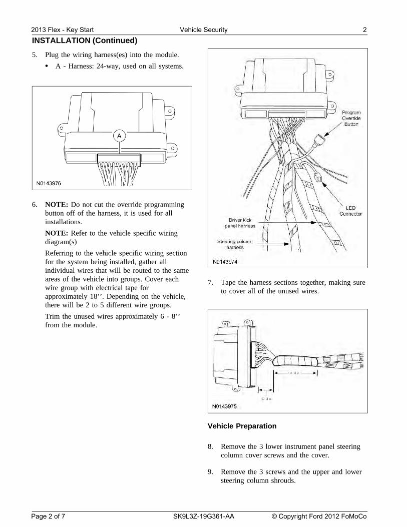
5. Plug the wiring harness(es) into the module.
• A - Harness: 24-way, used on all systems.
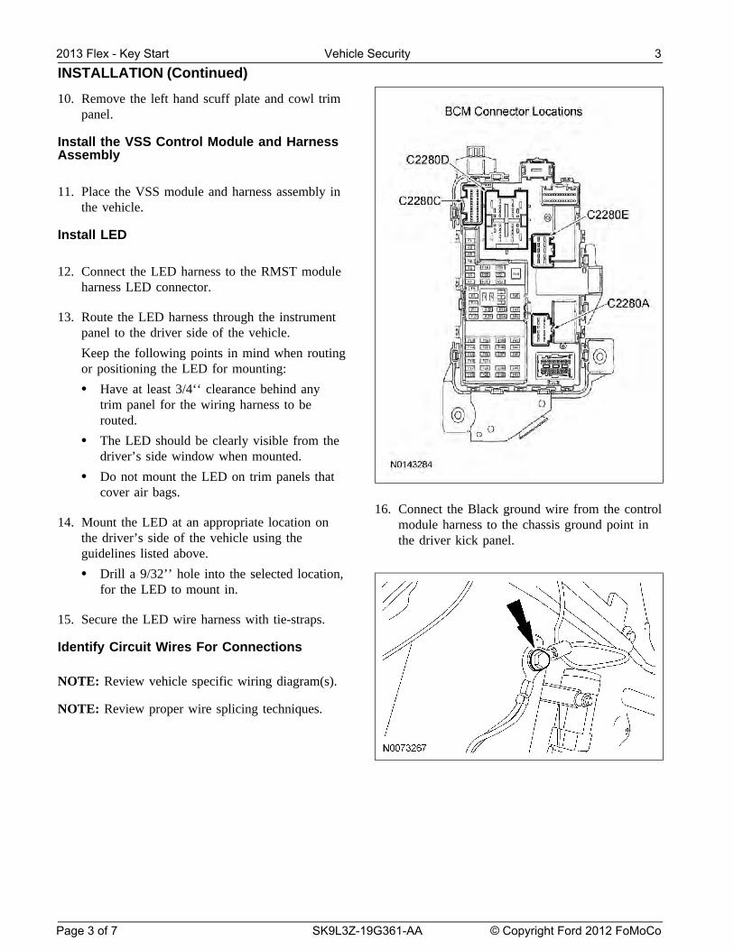
6. NOTE: Do not cut the override programmingbutton off of the harness, it is used for allinstallations.
NOTE: Refer to the vehicle specific wiringdiagram(s)
Referring to the vehicle specific wiring sectionfor the system being installed, gather allindividual wires that will be routed to the sameareas of the vehicle into groups. Cover eachwire group with electrical tape forapproximately 18’’. Depending on the vehicle,there will be 2 to 5 different wire groups.
Trim the unused wires approximately 6 - 8’’from the module.
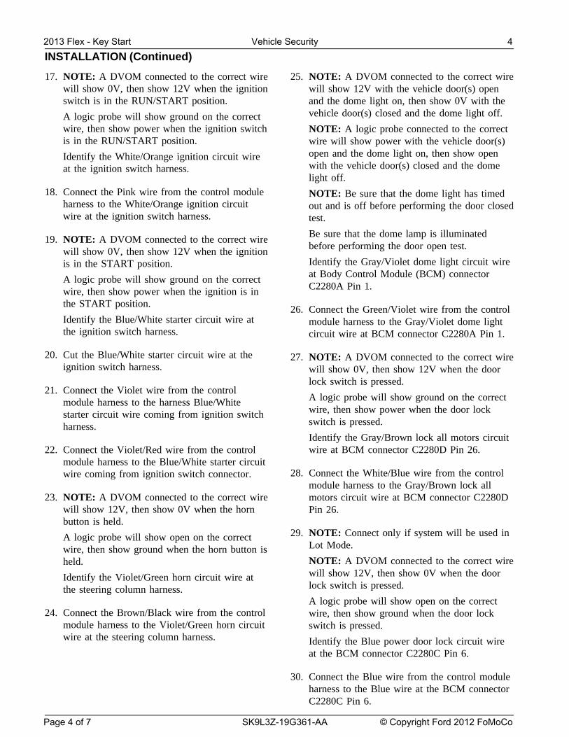
7. Tape the harness sections together, making sureto cover all of the unused wires.
Vehicle Preparation
8. Remove the 3 lower instrument panel steeringcolumn cover screws and the cover.
9. Remove the 3 screws and the upper and lowersteering column shrouds.
2013 Flex - Key Start Vehicle Security 2
Page 2 of 7 SK9L3Z-19G361-AA © Copyright Ford 2012 FoMoCo
INSTALLATION (Continued)
10. Remove the left hand scuff plate and cowl trimpanel.
Install the VSS Control Module and HarnessAssembly
11. Place the VSS module and harness assembly inthe vehicle.
Install LED
12. Connect the LED harness to the RMST moduleharness LED connector.
13. Route the LED harness through the instrumentpanel to the driver side of the vehicle.
Keep the following points in mind when routingor positioning the LED for mounting:
• Have at least 3/4‘‘ clearance behind anytrim panel for the wiring harness to berouted.
• The LED should be clearly visible from thedriver’s side window when mounted.
• Do not mount the LED on trim panels thatcover air bags.
16. Connect the Black ground wire from the control14. Mount the LED at an appropriate location on module harness to the chassis ground point in
the driver’s side of the vehicle using the the driver kick panel.guidelines listed above.
• Drill a 9/32’’ hole into the selected location,for the LED to mount in.
15. Secure the LED wire harness with tie-straps.
Identify Circuit Wires For Connections
NOTE: Review vehicle specific wiring diagram(s).
NOTE: Review proper wire splicing techniques.
2013 Flex - Key Start Vehicle Security 3
Page 3 of 7 SK9L3Z-19G361-AA © Copyright Ford 2012 FoMoCo
INSTALLATION (Continued)
17. NOTE: A DVOM connected to the correct wire 25. NOTE: A DVOM connected to the correct wirewill show 0V, then show 12V when the ignition will show 12V with the vehicle door(s) openswitch is in the RUN/START position. and the dome light on, then show 0V with the
vehicle door(s) closed and the dome light off.A logic probe will show ground on the correctwire, then show power when the ignition switch NOTE: A logic probe connected to the correctis in the RUN/START position. wire will show power with the vehicle door(s)
open and the dome light on, then show openIdentify the White/Orange ignition circuit wirewith the vehicle door(s) closed and the domeat the ignition switch harness.light off.
18. Connect the Pink wire from the control module NOTE: Be sure that the dome light has timedharness to the White/Orange ignition circuit out and is off before performing the door closedwire at the ignition switch harness. test.
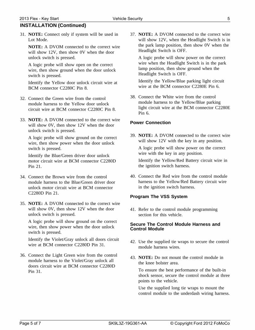
Be sure that the dome lamp is illuminated19. NOTE: A DVOM connected to the correct wirebefore performing the door open test.will show 0V, then show 12V when the ignitionIdentify the Gray/Violet dome light circuit wireis in the START position.at Body Control Module (BCM) connectorA logic probe will show ground on the correctC2280A Pin 1.wire, then show power when the ignition is in
the START position.26. Connect the Green/Violet wire from the control
Identify the Blue/White starter circuit wire at module harness to the Gray/Violet dome lightthe ignition switch harness. circuit wire at BCM connector C2280A Pin 1.
20. Cut the Blue/White starter circuit wire at the 27. NOTE: A DVOM connected to the correct wireignition switch harness. will show 0V, then show 12V when the door
lock switch is pressed.21. Connect the Violet wire from the control
A logic probe will show ground on the correctmodule harness to the harness Blue/Whitewire, then show power when the door lockstarter circuit wire coming from ignition switchswitch is pressed.harness.Identify the Gray/Brown lock all motors circuitwire at BCM connector C2280D Pin 26.22. Connect the Violet/Red wire from the control
module harness to the Blue/White starter circuit28. Connect the White/Blue wire from the controlwire coming from ignition switch connector.
module harness to the Gray/Brown lock all23. NOTE: A DVOM connected to the correct wire motors circuit wire at BCM connector C2280D
will show 12V, then show 0V when the horn Pin 26.button is held.
29. NOTE: Connect only if system will be used inA logic probe will show open on the correctLot Mode.wire, then show ground when the horn button isNOTE: A DVOM connected to the correct wireheld.will show 12V, then show 0V when the doorIdentify the Violet/Green horn circuit wire atlock switch is pressed.the steering column harness.A logic probe will show open on the correct
24. Connect the Brown/Black wire from the control wire, then show ground when the door lockmodule harness to the Violet/Green horn circuit switch is pressed.wire at the steering column harness. Identify the Blue power door lock circuit wire
at the BCM connector C2280C Pin 6.
30. Connect the Blue wire from the control moduleharness to the Blue wire at the BCM connectorC2280C Pin 6.
2013 Flex - Key Start Vehicle Security 4
Page 4 of 7 SK9L3Z-19G361-AA © Copyright Ford 2012 FoMoCo
INSTALLATION (Continued)
31. NOTE: Connect only if system will be used in 37. NOTE: A DVOM connected to the correct wireLot Mode. will show 12V, when the Headlight Switch is in
the park lamp position, then show 0V when theNOTE: A DVOM connected to the correct wireHeadlight Switch is OFF.will show 12V, then show 0V when the door
unlock switch is pressed. A logic probe will show power on the correctwire when the Headlight Switch is in the parkA logic probe will show open on the correctlamp position, then show ground when thewire, then show ground when the door unlockHeadlight Switch is OFF.switch is pressed.Identify the Yellow/Blue parking light circuitIdentify the Yellow door unlock circuit wire atwire at the BCM connector C2280E Pin 6.BCM connector C2280C Pin 8.
38. Connect the White wire from the control32. Connect the Green wire from the controlmodule harness to the Yellow/Blue parkingmodule harness to the Yellow door unlocklight circuit wire at the BCM connector C2280Ecircuit wire at BCM connector C2280C Pin 8.Pin 6.
33. NOTE: A DVOM connected to the correct wirePower Connectionwill show 0V, then show 12V when the door
unlock switch is pressed.39. NOTE: A DVOM connected to the correct wireA logic probe will show ground on the correct
will show 12V with the key in any position.wire, then show power when the door unlockA logic probe will show power on the correctswitch is pressed.wire with the key in any position.Identify the Blue/Green driver door unlockIdentify the Yellow/Red Battery circuit wire inmotor circuit wire at BCM connector C2280Dthe ignition switch harness.Pin 21.
40. Connect the Red wire from the control module34. Connect the Brown wire from the controlharness to the Yellow/Red Battery circuit wiremodule harness to the Blue/Green driver doorin the ignition switch harness.unlock motor circuit wire at BCM connector
C2280D Pin 21.Program The VSS System
35. NOTE: A DVOM connected to the correct wirewill show 0V, then show 12V when the door 41. Refer to the control module programmingunlock switch is pressed. section for this vehicle.
A logic probe will show ground on the correctSecure The Control Module Harness andwire, then show power when the door unlock Control Module
switch is pressed.
Identify the Violet/Gray unlock all doors circuit 42. Use the supplied tie wraps to secure the controlwire at BCM connector C2280D Pin 31. module harness wires.
36. Connect the Light Green wire from the control 43. NOTE: Do not mount the control module inmodule harness to the Violet/Gray unlock all the knee bolster area.doors circuit wire at BCM connector C2280D
To ensure the best performance of the built-inPin 31.shock sensor, secure the control module at threepoints to the vehicle.
Use the supplied long tie wraps to mount thecontrol module to the underdash wiring harness.
2013 Flex - Key Start Vehicle Security 5
Page 5 of 7 SK9L3Z-19G361-AA © Copyright Ford 2012 FoMoCo

INSTALLATION (Continued)
Install Trim NOTE: Perform proper adjustments following the00Shock Sensor Setting11, refer to GeneralProcedures.44. Install the left hand scuff plate and cowl trim
panel.48. Open the driver door.
45. Install the upper and lower steering column All other doors should remain closed.shrouds.
49. Turn the ignition key to the RUN position.Install the 3 screws.
50. Press and hold the VSS override button for at46. Install the lower steering column opening cover.least 10 seconds. After 10 seconds the horn
Install the 2 screws. with honk 3 times, indicating the system is now• Tighten to 2.5 Nm (22 lb-in). in the learn mode.
Programming the Module 51. Press and release the override button. The hornwill honk 4 times indicating the system has
NOTE: Make sure that the hood and doors are entered the first program bank.closed before proceeding. If not please check the following:
• All door and dome light circuit wire solderNOTE: The LED on the VSS harness must beconnections.visible to complete module programming.
• The key is in the RUN position.NOTE: The VSS override button must be
• The software cartridge is firmly seated inaccessible.the VSS module.
47. Programming Options: Entering • The VSS harness connections are firmlyProgramming Mode seated in the VSS module.See chart(s) below for programming
NOTE: If you require additional assistance: CALLinformation.1-800-FORD KEY.
Option Bank - 1 Chart (4 - Honks)52. Press and release the Lock button on the trim
BANK OPTIONS DESCR LED switch 3 times. The horn will honk 3 times1 1 LITE NOTE 1 indicating the system has entered the option 3
TOUCH of the first program bank.ADJUST
1 2 FULL NOTE 1 NOTICE: To turn the LED on or off, press andSHOCK immediately release Unlock button on the trimADJUST switch.
1 3 DOOR ONAJAR 53. The LED must be ON for option 3. If the LED
INVERT is illuminated no action is required. If the LED1 4 UNLOCK ON is not illuminated press the Unlock button and
SENSE verify the LED illuminates.INVERT
Option Bank - 2 Chart (5 - Honks)
BANK OPTIONS DESCR LED
2 1 STARTER ONINTERRUPT
2013 Flex - Key Start Vehicle Security 6
Page 6 of 7 SK9L3Z-19G361-AA © Copyright Ford 2012 FoMoCo
INSTALLATION (Continued)
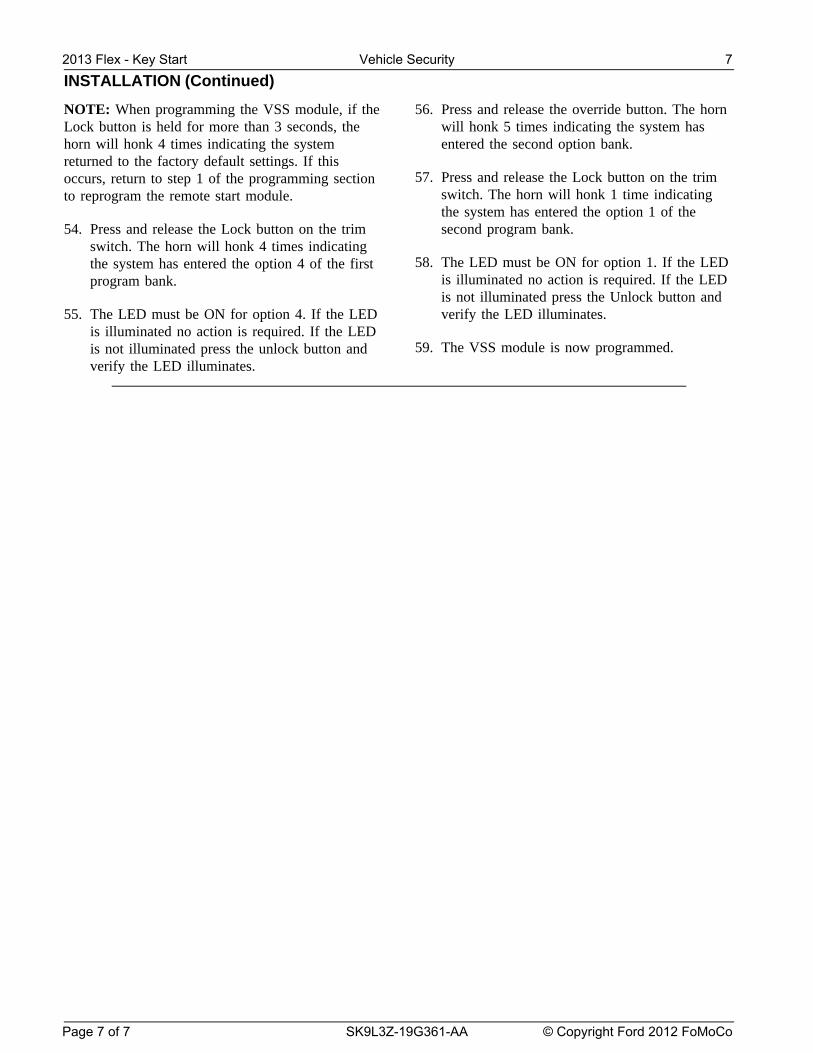
NOTE: When programming the VSS module, if the 56. Press and release the override button. The hornLock button is held for more than 3 seconds, the will honk 5 times indicating the system hashorn will honk 4 times indicating the system entered the second option bank.returned to the factory default settings. If this
57. Press and release the Lock button on the trimoccurs, return to step 1 of the programming sectionswitch. The horn will honk 1 time indicatingto reprogram the remote start module.the system has entered the option 1 of the
54. Press and release the Lock button on the trim second program bank.switch. The horn will honk 4 times indicating
58. The LED must be ON for option 1. If the LEDthe system has entered the option 4 of the firstis illuminated no action is required. If the LEDprogram bank.is not illuminated press the Unlock button and
55. The LED must be ON for option 4. If the LED verify the LED illuminates.is illuminated no action is required. If the LED
59. The VSS module is now programmed.is not illuminated press the unlock button andverify the LED illuminates.
2013 Flex - Key Start Vehicle Security 7
Page 7 of 7 SK9L3Z-19G361-AA © Copyright Ford 2012 FoMoCo
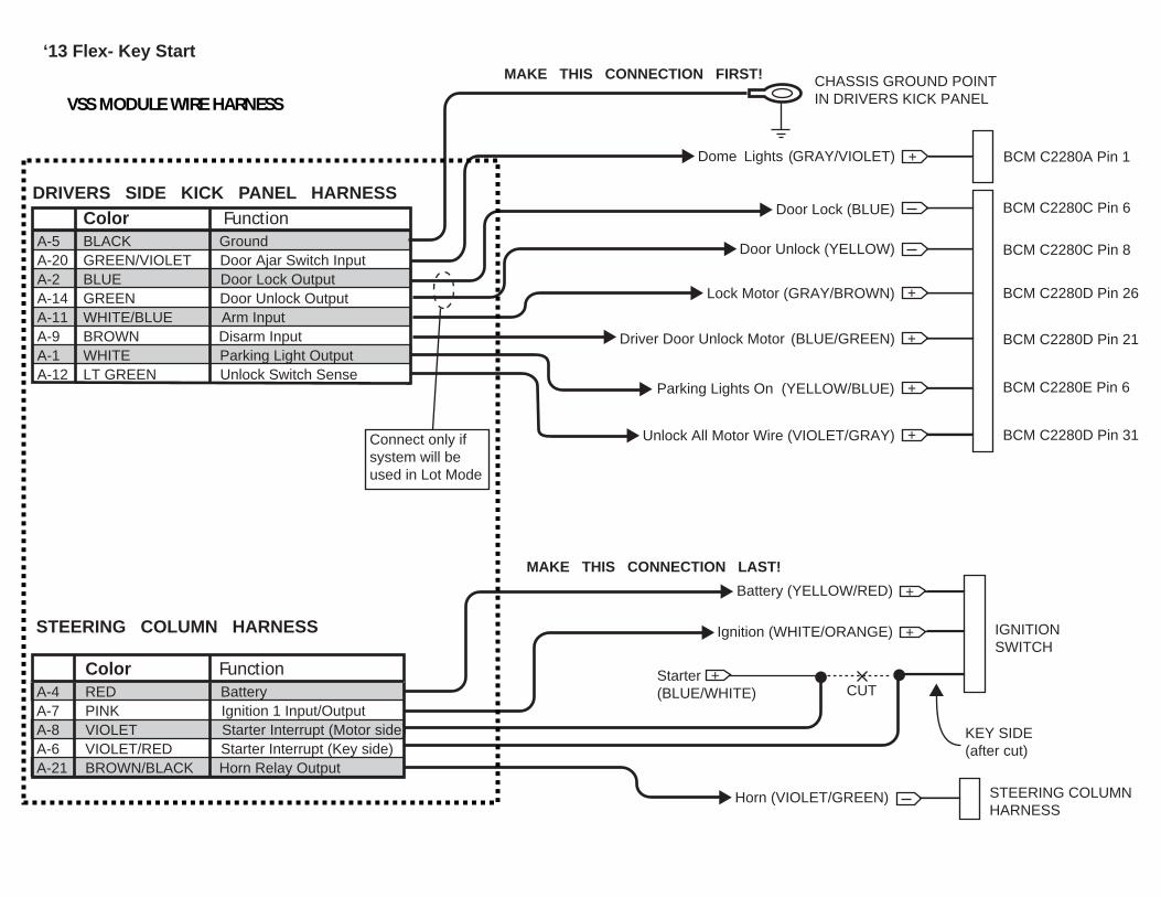
‘13 Flex- Key Start
Color FunctionA-5 BLACK GroundA-20 GREEN/VIOLET Door Ajar Switch InputA-2 BLUE Door Lock Output A-14 GREEN Door Unlock OutputA-11 WHITE/BLUE Arm Input A-9 BROWN Disarm InputA-1 WHITE Parking Light OutputA-12 LT GREEN Unlock Switch Sense
DRIVERS SIDE KICK PANEL HARNESS
CHASSIS GROUND POINTIN DRIVERS KICK PANEL
MAKE THIS CONNECTION FIRST!
Dome Lights (GRAY/VIOLET)
+
+
Door Lock (BLUE)
Door Unlock (YELLOW)
Lock Motor (GRAY/BROWN)
Driver Door Unlock Motor (BLUE/GREEN)
+Unlock All Motor Wire (VIOLET/GRAY)
Color FunctionA-4 RED BatteryA-7 PINK Ignition 1 Input/OutputA-8 VIOLET Starter Interrupt (Motor side)A-6 VIOLET/RED Starter Interrupt (Key side)A-21 BROWN/BLACK Horn Relay Output
IGNITIONSWITCH
Battery (YELLOW/RED)
Starter(BLUE/WHITE)
Ignition (WHITE/ORANGE)
STEERING COLUMNHARNESS
Horn (VIOLET/GREEN)
STEERING COLUMN HARNESS
+
+
+
CUT
KEY SIDE(after cut)
MAKE THIS CONNECTION LAST!
Connect only if system will be used in Lot Mode
+Parking Lights On (YELLOW/BLUE)
VSS MODULE WIRE HARNESS
BCM C2280C Pin 6
BCM C2280C Pin 8
BCM C2280D Pin 26
BCM C2280D Pin 21
BCM C2280E Pin 6
BCM C2280D Pin 31
+ BCM C2280A Pin 1
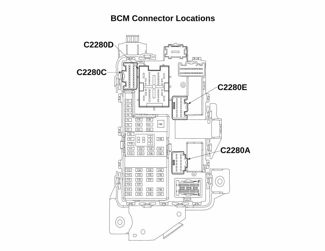
BCM Connector Locations
F1
F2
F19
F20
F21
F30
F31
F32
F3
F4
F5
F6
F7
F13
F14
F15
F16
F17
F18
F24
F25
F26
F27
F28
F29
F43
F44
F45
F46
F47
F35
F36
F37
F38
F39
F9
F8
F10
F11
F12
F22
F23
F40
F41
F42
F33
F34
F48
23 5 4
1
C2280D
C2280C
C2280E
C2280A

Manual Table of Contents
VSS SYSTEM INSTALLATIONCONTENTS
INSTALLATIONVSS
Contents SK9L3Z-19A361-AA © Copyright Ford 2012 FoMoCo
2013 Escape Vehicle Security
Shock Sensor Sensitivity Adjustment VSS Functional Test
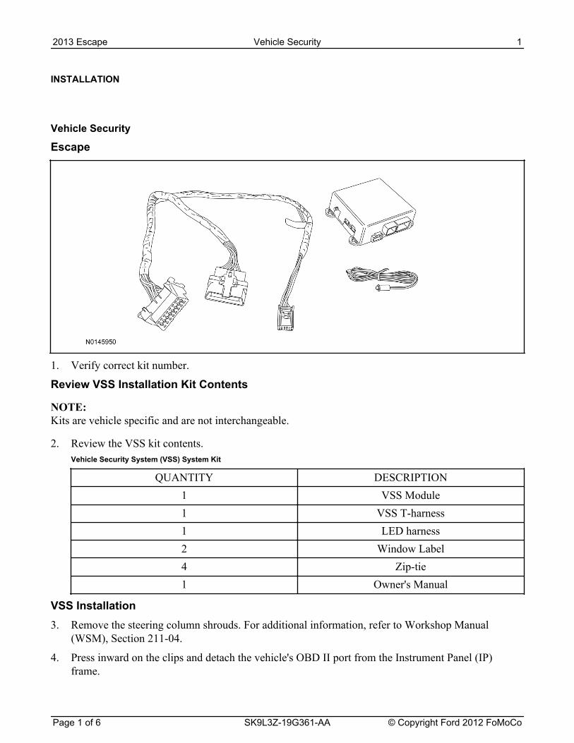
INSTALLATION
Vehicle Security
Escape
1. Verify correct kit number.
Review VSS Installation Kit Contents
NOTE: Kits are vehicle specific and are not interchangeable.
2. Review the VSS kit contents.Vehicle Security System (VSS) System Kit
QUANTITY DESCRIPTION1 VSS Module1 VSS T-harness1 LED harness2 Window Label4 Zip-tie1 Owner's Manual
VSS Installation3. Remove the steering column shrouds. For additional information, refer to Workshop Manual
(WSM), Section 211-04.
4. Press inward on the clips and detach the vehicle's OBD II port from the Instrument Panel (IP)frame.
2013 Escape Vehicle Security 1
Page 1 of 6 SK9L3Z-19G361-AA © Copyright Ford 2012 FoMoCo
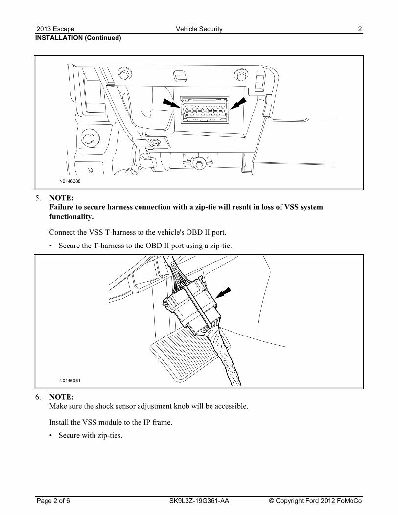
5. NOTE: Failure to secure harness connection with a zip-tie will result in loss of VSS systemfunctionality.
Connect the VSS T-harness to the vehicle's OBD II port.
• Secure the T-harness to the OBD II port using a zip-tie.
6. NOTE: Make sure the shock sensor adjustment knob will be accessible.
Install the VSS module to the IP frame.
• Secure with zip-ties.
INSTALLATION (Continued)2013 Escape Vehicle Security 2
Page 2 of 6 SK9L3Z-19G361-AA © Copyright Ford 2012 FoMoCo
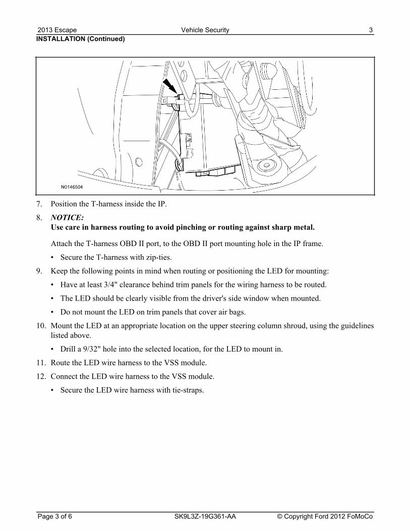
7. Position the T-harness inside the IP.
8. NOTICE: Use care in harness routing to avoid pinching or routing against sharp metal.
Attach the T-harness OBD II port, to the OBD II port mounting hole in the IP frame.
• Secure the T-harness with zip-ties.
9. Keep the following points in mind when routing or positioning the LED for mounting:
• Have at least 3/4" clearance behind trim panels for the wiring harness to be routed.
• The LED should be clearly visible from the driver's side window when mounted.
• Do not mount the LED on trim panels that cover air bags.
10. Mount the LED at an appropriate location on the upper steering column shroud, using the guidelineslisted above.
• Drill a 9/32" hole into the selected location, for the LED to mount in.
11. Route the LED wire harness to the VSS module.
12. Connect the LED wire harness to the VSS module.
• Secure the LED wire harness with tie-straps.
INSTALLATION (Continued)2013 Escape Vehicle Security 3
Page 3 of 6 SK9L3Z-19G361-AA © Copyright Ford 2012 FoMoCo
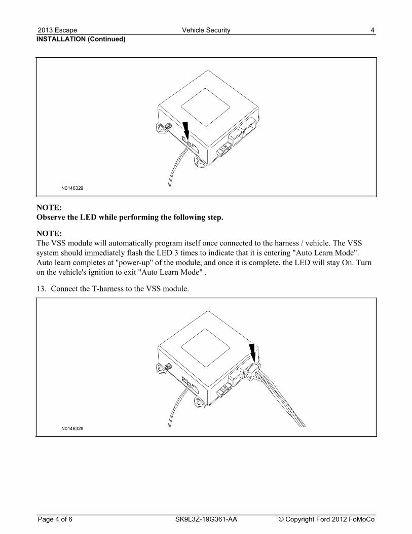
NOTE: Observe the LED while performing the following step.
NOTE: The VSS module will automatically program itself once connected to the harness / vehicle. The VSSsystem should immediately flash the LED 3 times to indicate that it is entering "Auto Learn Mode".Auto learn completes at "power-up" of the module, and once it is complete, the LED will stay On. Turnon the vehicle's ignition to exit "Auto Learn Mode" .
13. Connect the T-harness to the VSS module.
INSTALLATION (Continued)2013 Escape Vehicle Security 4
Page 4 of 6 SK9L3Z-19G361-AA © Copyright Ford 2012 FoMoCo
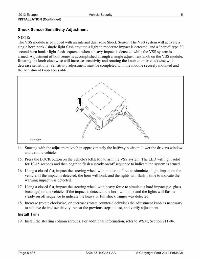
Rotating the knob clockwise will increase sensitivity and rotating the knob counter-clockwise willdecrease sensitivity. Sensitivity adjustment must be completed with the module securely mounted andthe adjustment knob accessible.
14. Starting with the adjustment knob in approximately the halfway position, lower the driver's windowand exit the vehicle.
15. Press the LOCK button on the vehicle's RKE fob to arm the VSS system. The LED will light solidfor 10-15 seconds and then begin to flash a steady on/off sequence to indicate the system is armed.
16. Using a closed fist, impact the steering wheel with moderate force to simulate a light impact on thevehicle. If the impact is detected, the horn will honk and the lights will flash 1 time to indicate thewarning impact was detected.
17. Using a closed fist, impact the steering wheel with heavy force to simulate a hard impact (i.e. glassbreakage) on the vehicle. If the impact is detected, the horn will honk and the lights will flash asteady on off sequence to indicate the heavy or full shock trigger was detected.
18. Increase (rotate clockwise) or decrease (rotate counter-clockwise) the adjustment knob as necessaryto achieve desired sensitivity, repeat the previous steps to test, and verify adjustment.
Install Trim19. Install the steering column shrouds. For additional information, refer to WSM, Section 211-04.
INSTALLATION (Continued)
Shock Sensor Sensitivity Adjustment
NOTE: The VSS module is equipped with an internal dual zone Shock Sensor. The VSS system will activate asingle horn honk / single light flash anytime a light to moderate impact is detected, and a "panic" type 30second horn honk / light flash sequence when a heavy impact is detected while the VSS system isarmed. Adjustment of both zones is accomplished through a single adjustment knob on the VSS module.
2013 Escape Vehicle Security 5
Page 5 of 6 SK9L3Z-19G361-AA © Copyright Ford 2012 FoMoCo
alarm should sound, indicating perimeter breach. Turn the alarm off by Turning the ignition to"On".
• If equipped with OE perimeter security, there will be a 12 second interior chime prior to alarmsounding. For vehicles not equipped with OE perimeter security, the alarm will trigger instantlyupon door opening.
• For push button start vehicles, the Intelligent Access (IA) key must be away from the vehicle,otherwise the security system will disarm immediately upon trigger.
22. Exit the vehicle and arm it again, this time leaving the driver's door open. The vehicle should armitself, ignoring the open door but monitoring the rest. Once the vehicle is armed, shut the driver'sdoor and reopen it after a few seconds. The alarm should sound. Turn the alarm off by hittingunlock on the keyfob.
• For push button start vehicles, the Intelligent Access (IA) key must be away from the vehicle,otherwise the security system will disarm immediately upon trigger.
23. Test all other vehicle doors and the trunk in the same manner, by setting off the alarm anddisarming with the keyfob.
INSTALLATION (Continued)
VSS Functional Test
NOTE: Observe the LED while performing these tests.
20. Lower the driver's door window, then close all doors, hood, and trunk/hatch and press lock on thekeyfob. The LED should stay lit for 10-15 seconds while the VSS system pre-arms, after which itwill flash every 3-4 seconds in fully armed mode.
21. Reach inside the window hit the door unlock trim switch. The LED should continue to flash,indicating that the vehicle is still armed. Use the inside driver's door handle to open the door. The
2013 Escape Vehicle Security 6
Page 6 of 6 SK9L3Z-19G361-AA © Copyright Ford 2012 FoMoCo

Manual Table of Contents
VSS SYSTEM INSTALLATIONCONTENTS
INSTALLATIONVSS
GENERAL PROCEDURES Proper Splicing Techniques Programming
Shock Sensor Setting
WIRING DIAGRAMS Vehicle Specific Wiring Diagrams
Vehicle Security
Contents SK9L3Z-19G361-AA © Copyright Ford 2012 FoMoCo
2013 Expedition/Naviagror
INSTALLATION
Vehicle Security System
Expedition/Navigator
NOTICE: Vehicle Security systems are onlyapplicable to vehicles with RKE.
1. Verify correct kit number.
Review VSS Installation Kit Contents
NOTE: Use kit number 7L3Z-19A361-AAVEHICLE SECURITY SYSTEM
NOTE: Kits are vehicle specific and are notinterchangeable.
2. Review the VSS kit contents.
Vehicle Security System (VSS) Kit
QUANTITY DESCRIPTION
1 MODULE ASSEMBLY
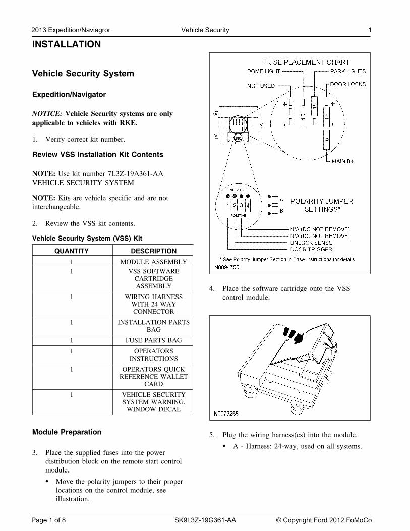
1 VSS SOFTWARECARTRIDGEASSEMBLY 4. Place the software cartridge onto the VSS
1 WIRING HARNESS control module.WITH 24-WAYCONNECTOR
1 INSTALLATION PARTSBAG
1 FUSE PARTS BAG
1 OPERATORSINSTRUCTIONS
1 OPERATORS QUICKREFERENCE WALLET
CARD
1 VEHICLE SECURITYSYSTEM WARNING.
WINDOW DECAL
Module Preparation 5. Plug the wiring harness(es) into the module.
• A - Harness: 24-way, used on all systems.3. Place the supplied fuses into the power
distribution block on the remote start controlmodule.
• Move the polarity jumpers to their properlocations on the control module, seeillustration.
2013 Expedition/Naviagror Vehicle Security 1
Page 1 of 8 SK9L3Z-19G361-AA © Copyright Ford 2012 FoMoCo
INSTALLATION (Continued)
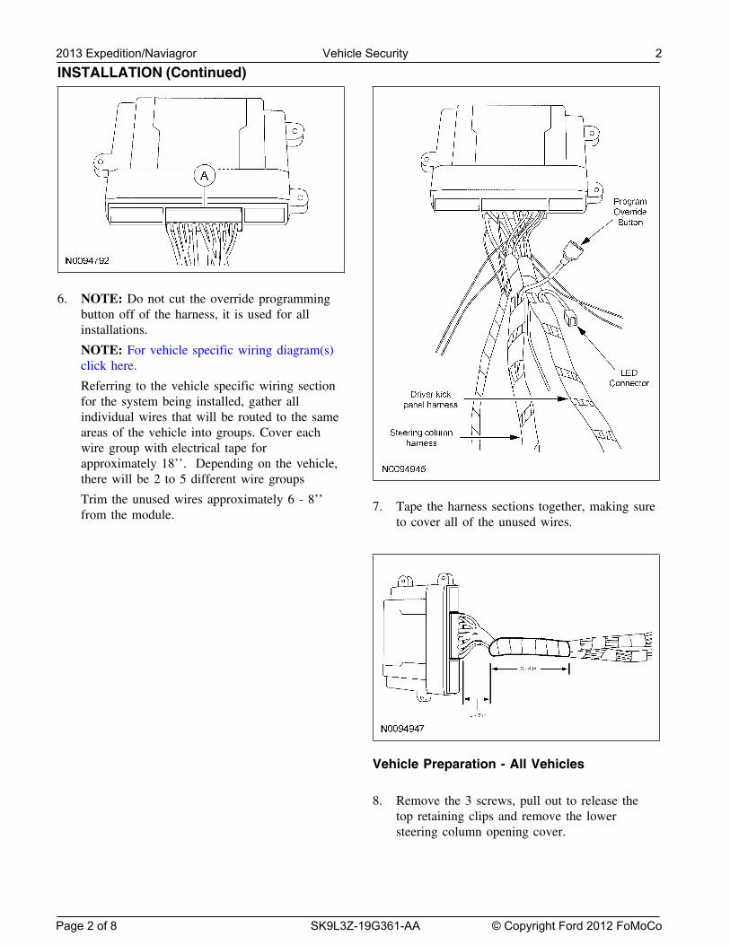
6. NOTE: Do not cut the override programmingbutton off of the harness, it is used for allinstallations.
NOTE: For vehicle specific wiring diagram(s)click here.
Referring to the vehicle specific wiring sectionfor the system being installed, gather allindividual wires that will be routed to the sameareas of the vehicle into groups. Cover eachwire group with electrical tape forapproximately 18’’. Depending on the vehicle,there will be 2 to 5 different wire groups
Trim the unused wires approximately 6 - 8’’ 7. Tape the harness sections together, making surefrom the module. to cover all of the unused wires.
Vehicle Preparation - All Vehicles
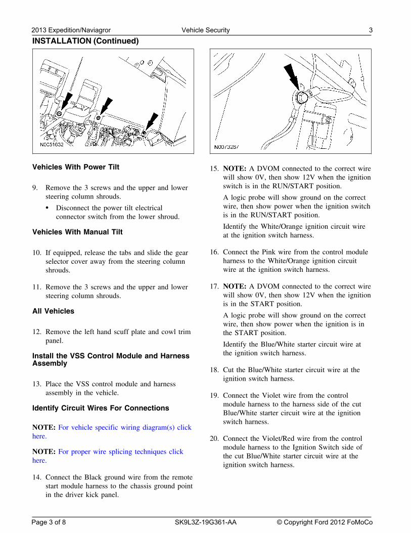
8. Remove the 3 screws, pull out to release thetop retaining clips and remove the lowersteering column opening cover.
2013 Expedition/Naviagror Vehicle Security 2
Page 2 of 8 SK9L3Z-19G361-AA © Copyright Ford 2012 FoMoCo
INSTALLATION (Continued)
Vehicles With Power Tilt 15. NOTE: A DVOM connected to the correct wirewill show 0V, then show 12V when the ignitionswitch is in the RUN/START position.9. Remove the 3 screws and the upper and lower
steering column shrouds. A logic probe will show ground on the correctwire, then show power when the ignition switch• Disconnect the power tilt electricalis in the RUN/START position.connector switch from the lower shroud.Identify the White/Orange ignition circuit wire
Vehicles With Manual Tilt at the ignition switch harness.
16. Connect the Pink wire from the control module10. If equipped, release the tabs and slide the gearharness to the White/Orange ignition circuitselector cover away from the steering columnwire at the ignition switch harness.shrouds.
17. NOTE: A DVOM connected to the correct wire11. Remove the 3 screws and the upper and lowerwill show 0V, then show 12V when the ignitionsteering column shrouds.is in the START position.
All Vehicles A logic probe will show ground on the correctwire, then show power when the ignition is in
12. Remove the left hand scuff plate and cowl trim the START position.panel. Identify the Blue/White starter circuit wire at
the ignition switch harness.Install the VSS Control Module and HarnessAssembly
18. Cut the Blue/White starter circuit wire at theignition switch harness.
13. Place the VSS control module and harnessassembly in the vehicle. 19. Connect the Violet wire from the control
module harness to the harness side of the cutIdentify Circuit Wires For ConnectionsBlue/White starter circuit wire at the ignitionswitch harness.
NOTE: For vehicle specific wiring diagram(s) clickhere. 20. Connect the Violet/Red wire from the control
module harness to the Ignition Switch side ofNOTE: For proper wire splicing techniques click
the cut Blue/White starter circuit wire at thehere.
ignition switch harness.
14. Connect the Black ground wire from the remotestart module harness to the chassis ground pointin the driver kick panel.
2013 Expedition/Naviagror Vehicle Security 3
Page 3 of 8 SK9L3Z-19G361-AA © Copyright Ford 2012 FoMoCo
INSTALLATION (Continued)
21. NOTE: A DVOM connected to the correct wire 27. NOTE: A DVOM connected to the correct wirewill show 12V, then show 0V when the horn will show 12V, when the Headlight Switch is inbutton is held. the park lamp position, then show 0V when the
Headlight Switch is OFF.A logic probe will show power on the correctwire, then show ground when the horn button is A logic probe will show power on the correctheld. wire when the Headlight Switch is in the park
lamp position, then show ground when theIdentify the Yellow/Red horn circuit wire in theHeadlight Switch is OFF.steering column harness.Identify the Violet/White parking light circuit
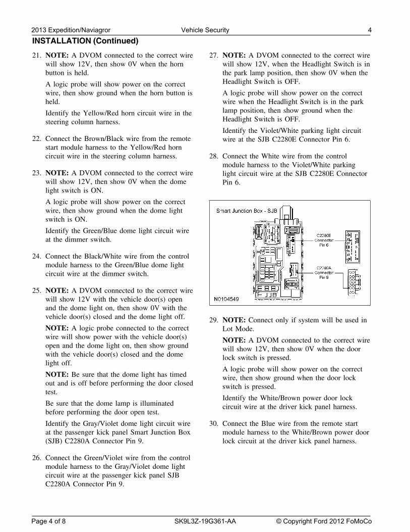
22. Connect the Brown/Black wire from the remote wire at the SJB C2280E Connector Pin 6.start module harness to the Yellow/Red horncircuit wire in the steering column harness. 28. Connect the White wire from the control
module harness to the Violet/White parking23. NOTE: A DVOM connected to the correct wire light circuit wire at the SJB C2280E Connector
will show 12V, then show 0V when the dome Pin 6.light switch is ON.
A logic probe will show power on the correctwire, then show ground when the dome lightswitch is ON.
Identify the Green/Blue dome light circuit wireat the dimmer switch.
24. Connect the Black/White wire from the controlmodule harness to the Green/Blue dome lightcircuit wire at the dimmer switch.
25. NOTE: A DVOM connected to the correct wirewill show 12V with the vehicle door(s) openand the dome light on, then show 0V with thevehicle door(s) closed and the dome light off. 29. NOTE: Connect only if system will be used inNOTE: A logic probe connected to the correct Lot Mode.wire will show power with the vehicle door(s) NOTE: A DVOM connected to the correct wireopen and the dome light on, then show ground will show 12V, then show 0V when the doorwith the vehicle door(s) closed and the dome lock switch is pressed.light off.
A logic probe will show power on the correctNOTE: Be sure that the dome light has timed wire, then show ground when the door lockout and is off before performing the door closed switch is pressed.test.
Identify the White/Brown power door lockBe sure that the dome lamp is illuminated circuit wire at the driver kick panel harness.before performing the door open test.
Identify the Gray/Violet dome light circuit wire 30. Connect the Blue wire from the remote startat the passenger kick panel Smart Junction Box module harness to the White/Brown power door(SJB) C2280A Connector Pin 9. lock circuit at the driver kick panel harness.
26. Connect the Green/Violet wire from the controlmodule harness to the Gray/Violet dome lightcircuit wire at the passenger kick panel SJBC2280A Connector Pin 9.
2013 Expedition/Naviagror Vehicle Security 4
Page 4 of 8 SK9L3Z-19G361-AA © Copyright Ford 2012 FoMoCo
INSTALLATION (Continued)
31. NOTE: Connect only if system will be used in 37. NOTE: A DVOM connected to the correct wireLot Mode. will show 0V, then show 12V when the door
unlock switch is pressed.NOTE: A DVOM connected to the correct wirewill show 12V, then show 0V when the door A logic probe will show ground on the correctunlock switch is pressed. wire, then show power when the door unlock
switch is pressed.A logic probe will show power on the correctwire, then show ground when the door unlock Identify the Violet/Gray Passenger Unlock Motorswitch is pressed. circuit wire at the passenger door sill plate
harness.Identify the Blue/Brown power door unlockcircuit wire at the driver kick panel harness.
38. Connect the Light Green wire from the controlmodule harness to the Violet/Gray Passenger 32. Connect the Green wire from the remote startUnlock Motor circuit wire at the passenger doormodule harness to the Blue/Brown power doorsill plate harness.unlock circuit at the driver kick panel harness.
Power Connection33. NOTE: A DVOM connected to the correct wirewill show 0V, then show 12V when the door
39. NOTE: A DVOM connected to the correct wirelock switch is pressed.will show 12V with the key in any position.A logic probe will show ground on the correctA logic probe will show power on the correctwire, then show power when the door lockwire with the key in any position.switch is pressed.
Identify two Blue/Red Battery circuit wire inIdentify the Gray/Brown lock all motors circuitthe ignition switch harness.wire at the driver kick panel.
40. Connect the one Red wire from the control34. Connect the White/Blue wire from the controlmodule harness to the one Blue/Red Batterymodule harness to the Gray/Brown lock allcircuit wire in the ignition switch harness.motors circuit wire at the driver kick panel.
Program The VSS System35. NOTE: A DVOM connected to the correct wirewill show 0V, then show 12V when the doorunlock switch is pressed. 41. Refer to the VSS programming section for this
vehicle (click here).A logic probe will show ground on the correctwire, then show power when the door unlock
Secure VSS Harness and Control Moduleswitch is pressed.
Identify the Blue/Green driver door unlock42. Use the supplied tie wraps to secure the VSScircuit wire at the driver kick panel harness.
harness wires.
36. Connect the Brown wire from the control43. NOTE: Do not mount the control module inmodule harness to the Blue/Green driver door
the knee bolster area.unlock circuit wire at the driver kick panelTo ensure the best performance of the built-inharness.shock sensor, secure the control module at threepoints to the vehicle.
Use the supplied long tie wraps to mount theVSS control module to the underdash wiringharness.
2013 Expedition/Naviagror Vehicle Security 5
Page 5 of 8 SK9L3Z-19G361-AA © Copyright Ford 2012 FoMoCo
INSTALLATION (Continued)
All Vehicles 47. Install the upper and lower steering columnshrouds.
44. Install the left hand scuff plate and cowl trim Install the 3 screws.panel.
All VehiclesVehicles With Manual Tilt
48. Install the lower steering column opening cover.45. Install the upper and lower steering column Install the 3 screws.
shrouds.
Install the 3 screws.
Vehicles With Power Tilt
46. Connect the power tilt electrical connectorswitch on the lower shroud.
2013 Expedition/Naviagror Vehicle Security 6
Page 6 of 8 SK9L3Z-19G361-AA © Copyright Ford 2012 FoMoCo
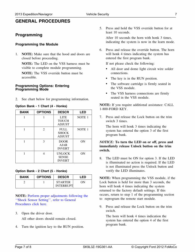
GENERAL PROCEDURES
5. Press and hold the VSS override button for atleast 10 seconds.
ProgrammingAfter 10 seconds the horn with honk 3 times,indicating the system is now in the learn mode.
Programming the Module
6. Press and release the override button. The hornwill honk 4 times indicating the system has1. NOTE: Make sure that the hood and doors areentered the first program bank.closed before proceeding.
If not please check the following:NOTE: The LED on the VSS harness must bevisible to complete module programming. • All door and dome light circuit wire solder
connections.NOTE: The VSS override button must beaccessible. • The key is in the RUN position.
• The software cartridge is firmly seated inProgramming Options: Enteringthe VSS module.Programming Mode
• The VSS harness connections are firmlyseated in the VSS module.2. See chart below for programming information.
NOTE: If you require additional assistance: CALLOption Bank - 1 Chart (4 - Honks)1-800-FORD KEY.
BANK OPTIONS DESCR LED
7. Press and release the Lock button on the trim1 1 LITE NOTE 1TOUCH switch 3 times.ADJUST
The horn will honk 3 times indicating the1 2 FULL NOTE 1 system has entered the option 3 of the first
SHOCK program bank.ADJUST
1 3 DOOR ON NOTICE: To turn the LED on or off, press andAJAR immediately release Unlock button on the trim
INVERT switch.1 4 UNLOCK ON
SENSE 8. The LED must be ON for option 3. If the LEDINVERT is illuminated no action is required. If the LED
is not illuminated press the Unlock button andverify the LED illuminates.Option Bank - 2 Chart (5 - Honks)
BANK OPTIONS DESCR LED NOTE: When programming the VSS module, if the2 1 STARTER ON Lock button is held for more than 3 seconds, the
INTERRUPT horn will honk 4 times indicating the systemreturned to the factory default settings. If thisoccurs, return to step 1 of the programming sectionNOTE: Perform proper adjustments following theto reprogram the remote start module.‘‘Shock Sensor Setting’’, refer to General
Procedures click here.9. Press and release the Lock button on the trim
switch.3. Open the driver door.
The horn will honk 4 times indication theAll other doors should remain closed. system has entered the option 4 of the first
program bank.4. Turn the ignition key to the RUN position.
2013 Expedition/Naviagror Vehicle Security 7
Page 7 of 8 SK9L3Z-19G361-AA © Copyright Ford 2012 FoMoCo
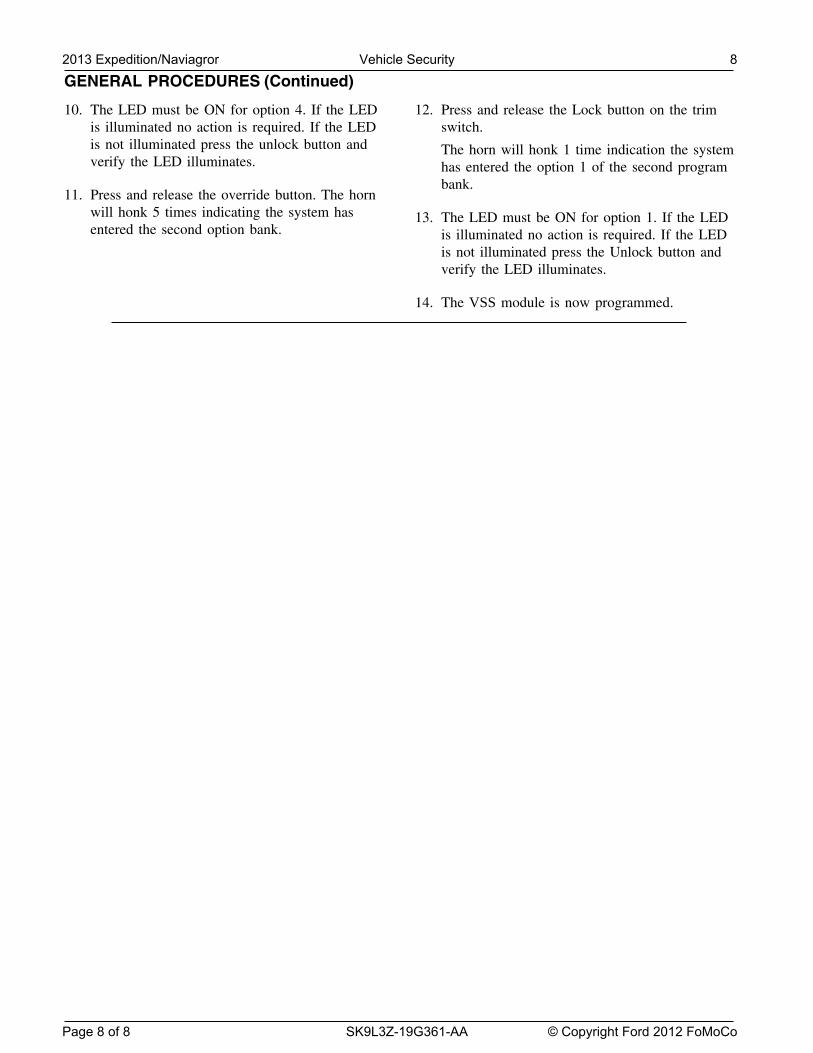
GENERAL PROCEDURES (Continued)
10. The LED must be ON for option 4. If the LED 12. Press and release the Lock button on the trimis illuminated no action is required. If the LED switch.is not illuminated press the unlock button and The horn will honk 1 time indication the systemverify the LED illuminates. has entered the option 1 of the second program
bank.11. Press and release the override button. The horn
will honk 5 times indicating the system has 13. The LED must be ON for option 1. If the LEDentered the second option bank. is illuminated no action is required. If the LED
is not illuminated press the Unlock button andverify the LED illuminates.
14. The VSS module is now programmed.
2013 Expedition/Naviagror Vehicle Security 8
Page 8 of 8 SK9L3Z-19G361-AA © Copyright Ford 2012 FoMoCo
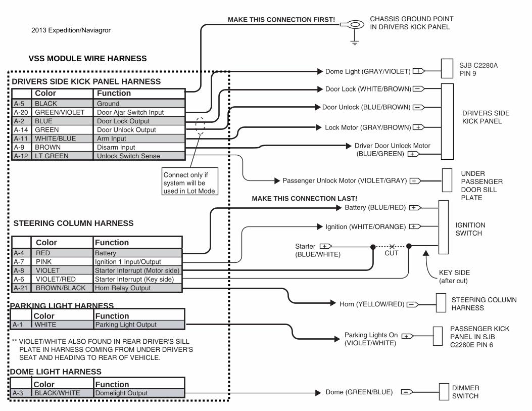
Color FunctionA-5 BLACK GroundA-20 GREEN/VIOLET Door Ajar Switch InputA-2 BLUE Door Lock Output A-14 GREEN Door Unlock OutputA-11 WHITE/BLUE Arm Input A-9 BROWN Disarm InputA-12 LT GREEN Unlock Switch Sense
DRIVERS SIDE KICK PANEL HARNESS
CHASSIS GROUND POINTIN DRIVERS KICK PANEL
MAKE THIS CONNECTION FIRST!
DRIVERS SIDEKICK PANEL
Dome Light (GRAY/VIOLET) +
+
+
Door Lock (WHITE/BROWN)
Door Unlock (BLUE/BROWN)
Lock Motor (GRAY/BROWN)
Driver Door Unlock Motor (BLUE/GREEN)
+Passenger Unlock Motor (VIOLET/GRAY)
Color FunctionA-4 RED Battery A-7 PINK Ignition 1 Input/OutputA-8 VIOLET Starter Interrupt (Motor side)A-6 VIOLET/RED Starter Interrupt (Key side)A-21 BROWN/BLACK Horn Relay Output
IGNITIONSWITCH
Battery (BLUE/RED)
Starter(BLUE/WHITE)
Ignition (WHITE/ORANGE)
STEERING COLUMNHARNESSHorn (YELLOW/RED)
STEERING COLUMN HARNESS
+
+
+
CUT
KEY SIDE(after cut)
MAKE THIS CONNECTION LAST!
UNDERPASSENGERDOOR SILL PLATE
Connect only if system will be used in Lot Mode
Parking Lights On(VIOLET/WHITE)
DIMMERSWITCH
Dome (GREEN/BLUE)
PARKING LIGHT HARNESS Color Function
A-1 WHITE Parking Light Output
DOME LIGHT HARNESS Color Function
A-3 BLACK/WHITE Domelight Output
** VIOLET/WHITE ALSO FOUND IN REAR DRIVER'S SILL PLATE IN HARNESS COMING FROM UNDER DRIVER'S SEAT AND HEADING TO REAR OF VEHICLE.
+PASSENGER KICKPANEL IN SJBC2280E PIN 6
VSS MODULE WIRE HARNESSSJB C2280APIN 9
2013 Expedition/Naviagror

Manual Table of Contents
VSS SYSTEM INSTALLATIONCONTENTS
INSTALLATIONVSS
GENERAL PROCEDURES Proper Splicing Techniques Programming Shock Sensor Setting WIRING DIAGRAMS Vehicle Specific Wiring Diagrams
2013 E-Series Vehicle Security
Contents SK9L3Z-19G361-AA © Copyright Ford 2012 FoMoCo
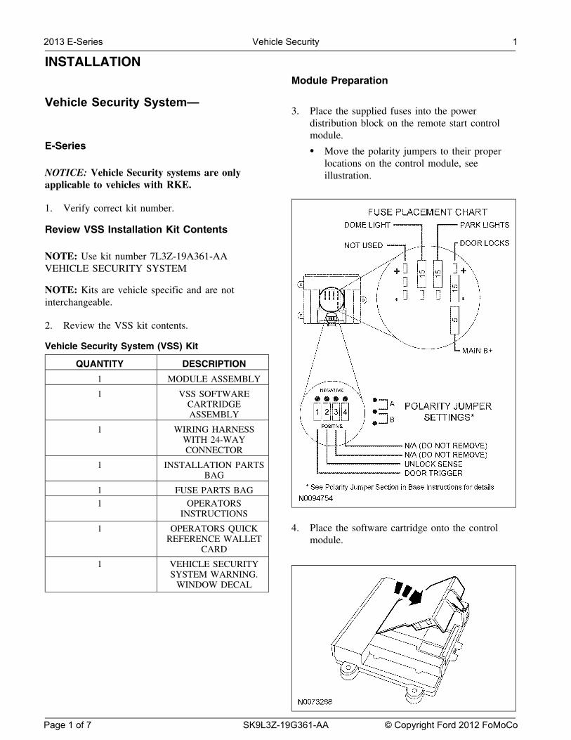
INSTALLATIONModule Preparation
Vehicle Security System—3. Place the supplied fuses into the power
distribution block on the remote start controlmodule.
E-Series • Move the polarity jumpers to their properlocations on the control module, see
NOTICE: Vehicle Security systems are only illustration.applicable to vehicles with RKE.
1. Verify correct kit number.
Review VSS Installation Kit Contents
NOTE: Use kit number 7L3Z-19A361-AAVEHICLE SECURITY SYSTEM
NOTE: Kits are vehicle specific and are notinterchangeable.
2. Review the VSS kit contents.
Vehicle Security System (VSS) Kit
QUANTITY DESCRIPTION
1 MODULE ASSEMBLY
1 VSS SOFTWARECARTRIDGEASSEMBLY
1 WIRING HARNESSWITH 24-WAYCONNECTOR
1 INSTALLATION PARTSBAG
1 FUSE PARTS BAG
1 OPERATORSINSTRUCTIONS
4. Place the software cartridge onto the control1 OPERATORS QUICKREFERENCE WALLET module.
CARD
1 VEHICLE SECURITYSYSTEM WARNING.
WINDOW DECAL
2013 E-Series Vehicle Security 1
Page 1 of 7 SK9L3Z-19G361-AA © Copyright Ford 2012 FoMoCo
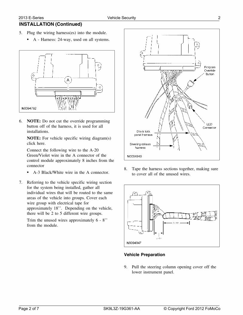
INSTALLATION (Continued)
5. Plug the wiring harness(es) into the module.
• A - Harness: 24-way, used on all systems.
6. NOTE: Do not cut the override programmingbutton off of the harness, it is used for allinstallations.
NOTE: For vehicle specific wiring diagram(s)click here.
Connect the following wire to the A-20Green/Violet wire in the A connector of thecontrol module approximately 8 inches from theconnector
8. Tape the harness sections together, making sure• A-3 Black/White wire in the A connector. to cover all of the unused wires.
7. Referring to the vehicle specific wiring sectionfor the system being installed, gather allindividual wires that will be routed to the sameareas of the vehicle into groups. Cover eachwire group with electrical tape forapproximately 18’’. Depending on the vehicle,there will be 2 to 5 different wire groups.
Trim the unused wires approximately 6 - 8’’from the module.
Vehicle Preparation
9. Pull the steering column opening cover off thelower instrument panel.
2013 E-Series Vehicle Security 2
Page 2 of 7 SK9L3Z-19G361-AA © Copyright Ford 2012 FoMoCo
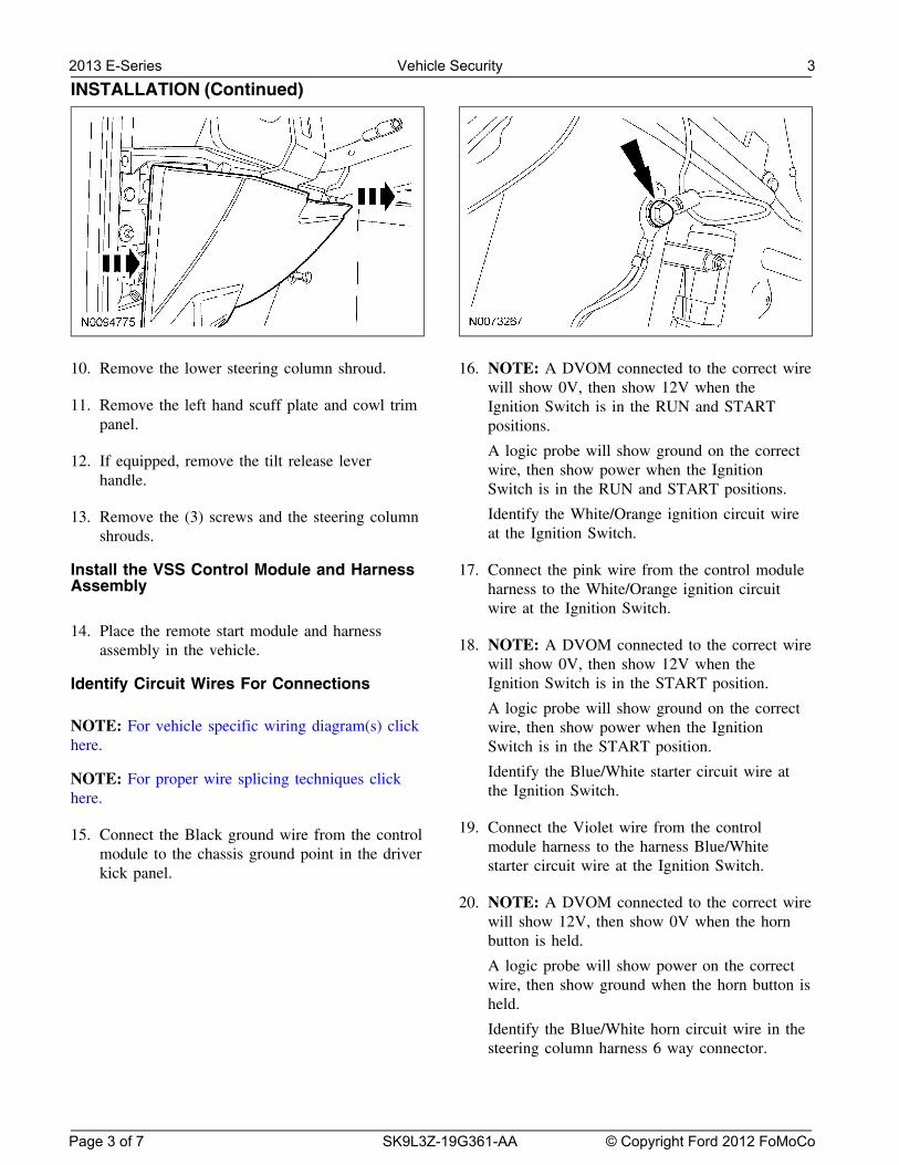
INSTALLATION (Continued)
10. Remove the lower steering column shroud. 16. NOTE: A DVOM connected to the correct wirewill show 0V, then show 12V when the
11. Remove the left hand scuff plate and cowl trim Ignition Switch is in the RUN and STARTpanel. positions.
A logic probe will show ground on the correct12. If equipped, remove the tilt release lever wire, then show power when the Ignition
handle. Switch is in the RUN and START positions.
Identify the White/Orange ignition circuit wire13. Remove the (3) screws and the steering columnat the Ignition Switch.shrouds.
Install the VSS Control Module and Harness 17. Connect the pink wire from the control moduleAssembly harness to the White/Orange ignition circuit
wire at the Ignition Switch.
14. Place the remote start module and harness18. NOTE: A DVOM connected to the correct wireassembly in the vehicle.
will show 0V, then show 12V when theIgnition Switch is in the START position.Identify Circuit Wires For Connections
A logic probe will show ground on the correctNOTE: For vehicle specific wiring diagram(s) click wire, then show power when the Ignitionhere. Switch is in the START position.
Identify the Blue/White starter circuit wire atNOTE: For proper wire splicing techniques clickthe Ignition Switch.here.
19. Connect the Violet wire from the control15. Connect the Black ground wire from the controlmodule harness to the harness Blue/Whitemodule to the chassis ground point in the driverstarter circuit wire at the Ignition Switch.kick panel.
20. NOTE: A DVOM connected to the correct wirewill show 12V, then show 0V when the hornbutton is held.
A logic probe will show power on the correctwire, then show ground when the horn button isheld.
Identify the Blue/White horn circuit wire in thesteering column harness 6 way connector.
2013 E-Series Vehicle Security 3
Page 3 of 7 SK9L3Z-19G361-AA © Copyright Ford 2012 FoMoCo
INSTALLATION (Continued)
21. Connect the Brown/Black wire from the control 27. Connect the Blue wire from the control moduleto the Gray/Yellow power door lock circuit atmodule to the Blue/White horn circuit wire atthe driver kick panel.the steering column harness 6 way connector.
28. NOTE: Connect only if system will be used in22. NOTE: A DVOM connected to the correct wireLot Mode.will show 0V with the switch in the OFF
position and 12V with the switch in the parking NOTE: A DVOM connected to the correct wirelights ON position. will show 12V, then show 0V when the door
unlock switch is pressed.A logic probe connected to the correct wire willshow ground with the switch in the OFF A logic probe will show open on the correctposition and power with the switch in the wire, then show ground when the door unlockparking lights ON position. switch is pressed.Identify the Violet/White parking lights on Identify the Violet/Gray power door unlockcircuit wire at the driver kick panel. circuit wire at the driver kick panel.
23. Connect the White wire from the control 29. Connect the Green wire from the controlmodule to the Violet/White parking lights on module to the Violet/Gray power door unlockcircuit wire at the driver kick panel. circuit at the driver kick panel.
24. NOTE: A DVOM connected to the correct wire 30. NOTE: A DVOM connected to the correct wirewill show 12V with the vehicle door(s) open will show 0V, then show 12V while depressingand the dome light on, then show 0V with the the door unlock switch.vehicle door(s) closed and the dome light off.
A logic probe will show ground on the correctNOTE: A logic probe connected to the correct wire, then show power while depressing thewire will show power with the vehicle door(s) door unlock switch.open and the dome light on, then show ground
Identify the Violet/Gray door unlock circuitwith the vehicle door(s) closed and the dome
wire at the driver kick panel.light off.
NOTE: Be sure that the dome light has timed 31. Connect the Light Green wire from the controlout and is off before performing the door closed module harness to the Violet/Gray door unlocktest. circuit wire at the driver kick panel.
Be sure that the dome lamp is illuminated32. NOTE: A DVOM connected to the correct wirebefore performing the door open test.
will show 0V, then show 12V while depressingIdentify the Gray/Violet dome light circuit wire the door lock switch.at the driver kick panel.
A logic probe will show ground on the correctwire, then show power while depressing the25. Connect the Green/Violet wire from the remotedoor lock switch.start module harness to the Gray/Violet dome
light circuit wire at the driver kick panel. Identify the Gray/Brown lock motor circuit wireat the driver kick panel.
26. NOTE: Connect only if system will be used inLot Mode. 33. Connect the White/Blue wire from the control
module harness to the Gray/Brown lock motorNOTE: A DVOM connected to the correct wirecircuit wire at the driver kick panel.will show 12V, then show 0V when the door
lock switch is pressed.
A logic probe will show open on the correctwire, then show ground when the door lockswitch is pressed.
Identify the Gray/Yellow power door lockcircuit wire at the driver kick panel.
2013 E-Series Vehicle Security 4
Page 4 of 7 SK9L3Z-19G361-AA © Copyright Ford 2012 FoMoCo
INSTALLATION (Continued)
Program The VSS System34. NOTE: A DVOM connected to the correct wirewill show 0V, then show 12V while depressingthe door unlock switch. 38. Refer to the VSS programming section for this
vehicle click here.A logic probe will show ground on the correctwire, then show power while depressing thedoor unlock switch. Secure VSS Harness and Control Module
Identify the Blue/Green driver door unlock39. Use the supplied tie wraps to secure the VSSmotor circuit wire at the driver kick panel.
harness wires.
35. Connect the Brown wire from the control40. NOTE: Do not mount the control module inmodule harness to the Blue/Green driver door
the knee bolster area.unlock motor circuit wire at the driver kickpanel. To ensure the best performance of the built-in
shock sensor, secure the control module at threePower Connection points to the vehicle.
Use the supplied long tie wraps to mount the36. NOTE: A DVOM connected to the correct wire VSS control module to the underdash wiring
will show 12V with the key in any position. harness.A logic probe will show power on the correct
Install Trimwire with the key in any position.
Identify two Blue/Red Battery circuit wires in41. Install the (3) screws and the steering columnthe ignition switch.
shroud.
37. Connect the one Red wire from the control42. If equipped, install the tilt release lever handle.module harness to one of the Blue/Red battery
circuit wire in the ignition switch.43. Install the lower instrument panel steering
column cover.
44. Install the left hand scuff plate and cowl trimpanel.
2013 E-Series Vehicle Security 5
Page 5 of 7 SK9L3Z-19G361-AA © Copyright Ford 2012 FoMoCo
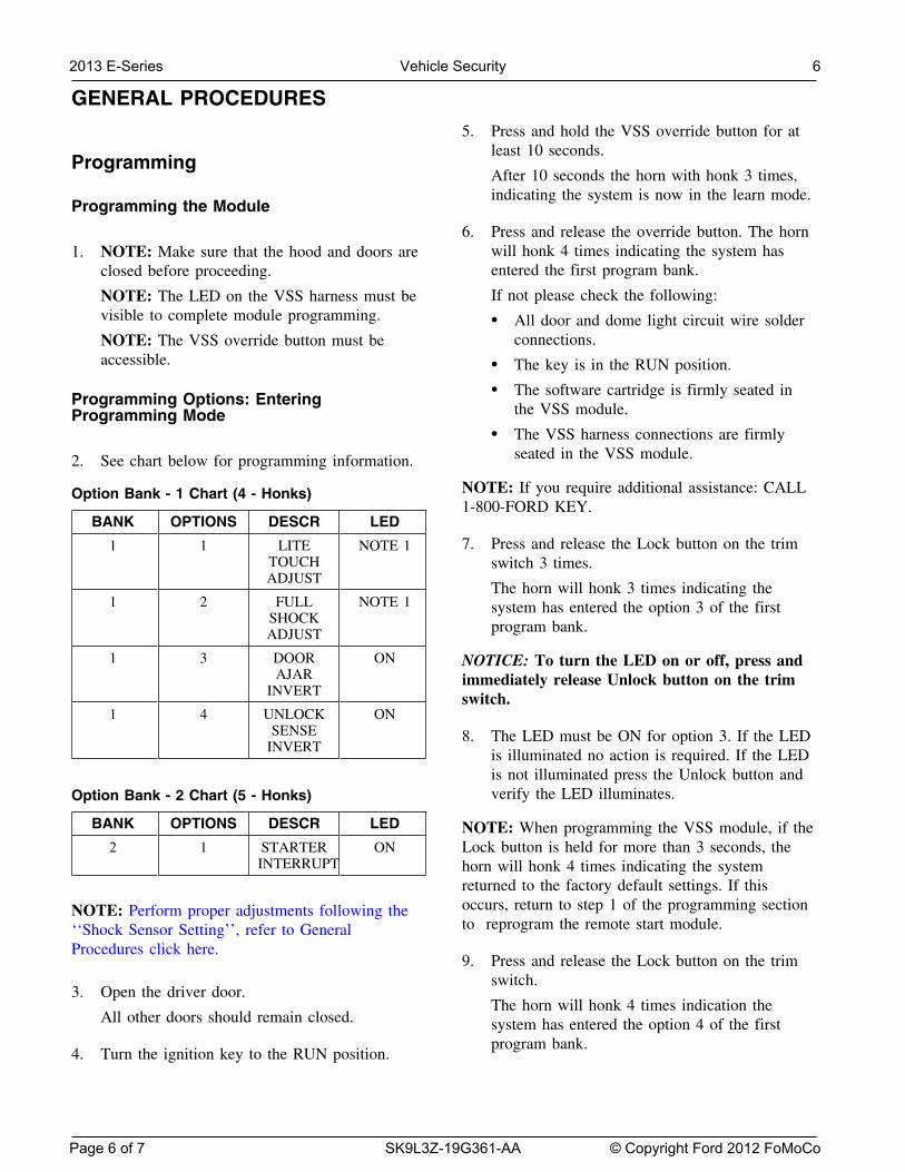
GENERAL PROCEDURES
5. Press and hold the VSS override button for atleast 10 seconds.
ProgrammingAfter 10 seconds the horn with honk 3 times,indicating the system is now in the learn mode.
Programming the Module
6. Press and release the override button. The hornwill honk 4 times indicating the system has1. NOTE: Make sure that the hood and doors areentered the first program bank.closed before proceeding.
If not please check the following:NOTE: The LED on the VSS harness must bevisible to complete module programming. • All door and dome light circuit wire solder
connections.NOTE: The VSS override button must beaccessible. • The key is in the RUN position.
• The software cartridge is firmly seated inProgramming Options: Enteringthe VSS module.Programming Mode
• The VSS harness connections are firmlyseated in the VSS module.2. See chart below for programming information.
NOTE: If you require additional assistance: CALLOption Bank - 1 Chart (4 - Honks)1-800-FORD KEY.
BANK OPTIONS DESCR LED
7. Press and release the Lock button on the trim1 1 LITE NOTE 1TOUCH switch 3 times.ADJUST
The horn will honk 3 times indicating the1 2 FULL NOTE 1 system has entered the option 3 of the first
SHOCK program bank.ADJUST
1 3 DOOR ON NOTICE: To turn the LED on or off, press andAJAR immediately release Unlock button on the trim
INVERT switch.1 4 UNLOCK ON
SENSE 8. The LED must be ON for option 3. If the LEDINVERT is illuminated no action is required. If the LED
is not illuminated press the Unlock button andverify the LED illuminates.Option Bank - 2 Chart (5 - Honks)
BANK OPTIONS DESCR LED NOTE: When programming the VSS module, if the2 1 STARTER ON Lock button is held for more than 3 seconds, the
INTERRUPT horn will honk 4 times indicating the systemreturned to the factory default settings. If thisoccurs, return to step 1 of the programming sectionNOTE: Perform proper adjustments following theto reprogram the remote start module.‘‘Shock Sensor Setting’’, refer to General
Procedures click here.9. Press and release the Lock button on the trim
switch.3. Open the driver door.
The horn will honk 4 times indication theAll other doors should remain closed. system has entered the option 4 of the first
program bank.4. Turn the ignition key to the RUN position.
2013 E-Series Vehicle Security 6
Page 6 of 7 SK9L3Z-19G361-AA © Copyright Ford 2012 FoMoCo
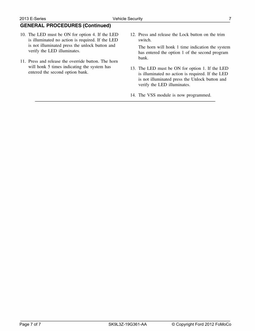
GENERAL PROCEDURES (Continued)
10. The LED must be ON for option 4. If the LED 12. Press and release the Lock button on the trimis illuminated no action is required. If the LED switch.is not illuminated press the unlock button and The horn will honk 1 time indication the systemverify the LED illuminates. has entered the option 1 of the second program
bank.11. Press and release the override button. The horn
will honk 5 times indicating the system has 13. The LED must be ON for option 1. If the LEDentered the second option bank. is illuminated no action is required. If the LED
is not illuminated press the Unlock button andverify the LED illuminates.
14. The VSS module is now programmed.
2013 E-Series Vehicle Security 7
Page 7 of 7 SK9L3Z-19G361-AA © Copyright Ford 2012 FoMoCo
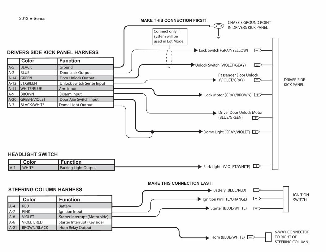
IGNITIONSWITCH
Battery (BLUE/RED)
Starter (BLUE/WHITE)
Ignition (WHITE/ORANGE)
6-WAY CONNECTOR TO RIGHT OFSTEERING COLUMN
Horn (BLUE/WHITE)
+
+
Color FunctionA-4 RED Battery A-7 PINK Ignition InputA-8 VIOLET Starter Interrupt (Motor side)A-6 VIOLET/RED Starter Interrupt (Key side)A-21 BROWN/BLACK Horn Relay Output
STEERING COLUMN HARNESSMAKE THIS CONNECTION LAST!
Color FunctionA-1 WHITE Parking Light Output
HEADLIGHT SWITCH
+
Dome Light (GRAY/VIOLET)
Park Lights (VIOLET/WHITE)
CHASSIS GROUND POINTIN DRIVERS KICK PANEL
MAKE THIS CONNECTION FIRST!
+
DRIVER SIDEKICK PANEL
+
Passenger Door Unlock (VIOLET/GRAY)
Lock Motor (GRAY/BROWN)
Driver Door Unlock Motor(BLUE/GREEN)
Color FunctionA-5 BLACK GroundA-2 BLUE Door Lock OutputA-14 GREEN Door Unlock OutputA-12 LT.GREEN Unlock Switch Sense InputA-11 WHITE/BLUE Arm Input A-9 BROWN Disarm InputA-20 GREEN/VIOLET Door Ajar Switch InputA-3 BLACK/WHITE Dome Light Output
DRIVERS SIDE KICK PANEL HARNESS
+
Lock Switch (GRAY/YELLOW)
Unlock Switch (VIOLET/GEAY)
+
Connect only if system will be used in Lot Mode.
+
2013 E-Series

Manual Table of Contents
VSS SYSTEM INSTALLATIONCONTENTS
INSTALLATIONVSS
GENERAL PROCEDURES Proper Splicing Techniques Programming Shock Sensor Setting WIRING DIAGRAMS Vehicle Specific Wiring Diagrams
Vehicle Security
Contents SK9L3Z-19G361-AA © Copyright Ford 2012 FoMoCo
2013 F-150
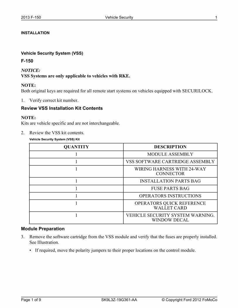
INSTALLATION
Vehicle Security System (VSS)
F-150
NOTICE: VSS Systems are only applicable to vehicles with RKE.
NOTE: Both original keys are required for all remote start systems on vehicles equipped with SECURILOCK.
1. Verify correct kit number.
Review VSS Installation Kit Contents
NOTE: Kits are vehicle specific and are not interchangeable.
2. Review the VSS kit contents.Vehicle Security System (VSS) Kit
QUANTITY DESCRIPTION1 MODULE ASSEMBLY1 VSS SOFTWARE CARTRIDGE ASSEMBLY1 WIRING HARNESS WITH 24-WAY
CONNECTOR1 INSTALLATION PARTS BAG1 FUSE PARTS BAG1 OPERATORS INSTRUCTIONS1 OPERATORS QUICK REFERENCE
WALLET CARD1 VEHICLE SECURITY SYSTEM WARNING.
WINDOW DECAL
Module Preparation3. Remove the software cartridge from the VSS module and verify that the fuses are properly installed.
See Illustration.
• If required, move the polarity jumpers to their proper locations on the control module.
2013 F-150 Vehicle Security 1
Page 1 of 9 SK9L3Z-19G361-AA © Copyright Ford 2012 FoMoCo
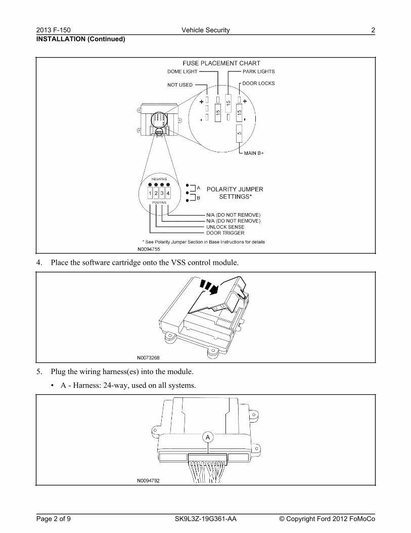
4. Place the software cartridge onto the VSS control module.
5. Plug the wiring harness(es) into the module.
• A - Harness: 24-way, used on all systems.
INSTALLATION (Continued)2013 F-150 Vehicle Security 2
Page 2 of 9 SK9L3Z-19G361-AA © Copyright Ford 2012 FoMoCo
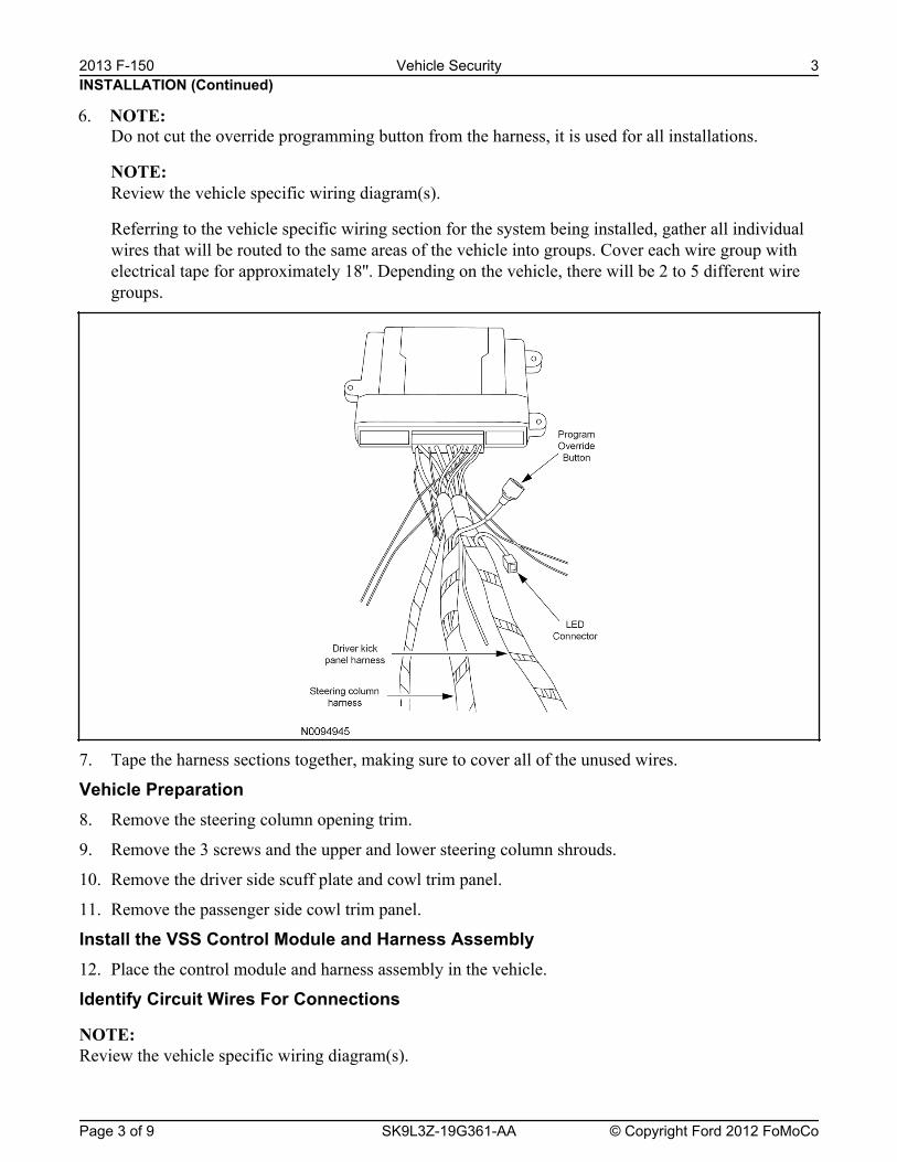
Do not cut the override programming button from the harness, it is used for all installations.
NOTE: Review the vehicle specific wiring diagram(s).
Referring to the vehicle specific wiring section for the system being installed, gather all individualwires that will be routed to the same areas of the vehicle into groups. Cover each wire group withelectrical tape for approximately 18''. Depending on the vehicle, there will be 2 to 5 different wiregroups.
7. Tape the harness sections together, making sure to cover all of the unused wires.
Vehicle Preparation8. Remove the steering column opening trim.
9. Remove the 3 screws and the upper and lower steering column shrouds.
10. Remove the driver side scuff plate and cowl trim panel.
11. Remove the passenger side cowl trim panel.
Install the VSS Control Module and Harness Assembly12. Place the control module and harness assembly in the vehicle.
Identify Circuit Wires For Connections
NOTE: Review the vehicle specific wiring diagram(s).
INSTALLATION (Continued)
6. NOTE:
2013 F-150 Vehicle Security 3
Page 3 of 9 SK9L3Z-19G361-AA © Copyright Ford 2012 FoMoCo
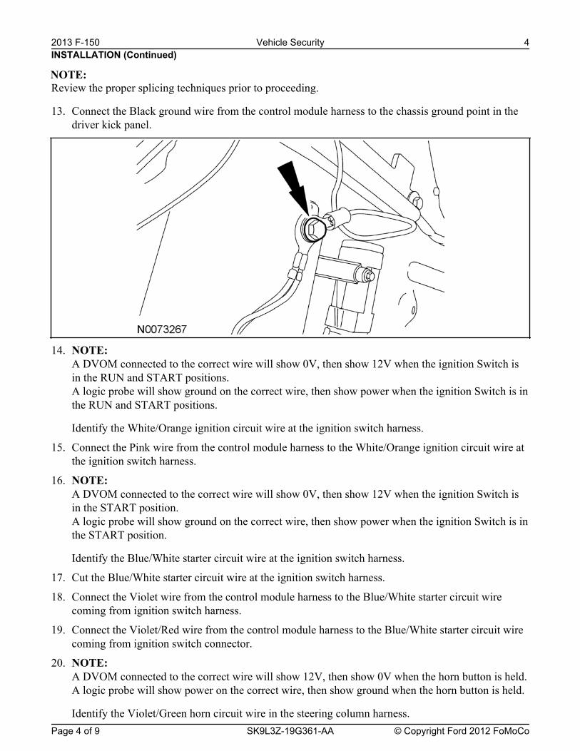
Review the proper splicing techniques prior to proceeding.
13. Connect the Black ground wire from the control module harness to the chassis ground point in thedriver kick panel.
14. NOTE: A DVOM connected to the correct wire will show 0V, then show 12V when the ignition Switch isin the RUN and START positions.A logic probe will show ground on the correct wire, then show power when the ignition Switch is inthe RUN and START positions.
Identify the White/Orange ignition circuit wire at the ignition switch harness.
15. Connect the Pink wire from the control module harness to the White/Orange ignition circuit wire atthe ignition switch harness.
16. NOTE: A DVOM connected to the correct wire will show 0V, then show 12V when the ignition Switch isin the START position.A logic probe will show ground on the correct wire, then show power when the ignition Switch is inthe START position.
Identify the Blue/White starter circuit wire at the ignition switch harness.
17. Cut the Blue/White starter circuit wire at the ignition switch harness.
18. Connect the Violet wire from the control module harness to the Blue/White starter circuit wirecoming from ignition switch harness.
19. Connect the Violet/Red wire from the control module harness to the Blue/White starter circuit wirecoming from ignition switch connector.
20. NOTE: A DVOM connected to the correct wire will show 12V, then show 0V when the horn button is held.A logic probe will show power on the correct wire, then show ground when the horn button is held.
Identify the Violet/Green horn circuit wire in the steering column harness.
INSTALLATION (Continued)
NOTE:
2013 F-150 Vehicle Security 4
Page 4 of 9 SK9L3Z-19G361-AA © Copyright Ford 2012 FoMoCo

21. Connect the Brown/Black wire from the control module harness to the Violet/Green horn circuitwire in the steering column harness.
22. NOTE: A DVOM connected to the correct wire will show 12V with the vehicle door(s) open and the domelight ON, then show 0V with the vehicle door(s) closed and the dome light OFF.
NOTE: A logic probe connected to the correct wire will show power with the vehicle door(s) open and thedome light ON, then show ground with the vehicle door(s) closed and the dome light OFF.
NOTE: Be sure that the dome light has timed out and is OFF before performing the door closed test.Be sure that the dome lamp is illuminated before performing the door open test.
Identify the Violet Cargo High Mounted Stop Lamp (CHMSL) circuit wire at one of the followinglocations:
• Passenger side door sill plate harness.
• Smart Junction Box (SJB) Connector C2280C Pin 1.
23. Connect the Green/Violet wire from the remote start module harness to the Violet CHMSL circuitwire at one of the following locations:
• Passenger side door sill plate harness.
• SJB Connector C2280C Pin 1.
24. NOTE: Connect only if system will be used in Lot Mode.
NOTE: A DVOM connected to the correct wire will show 12V, then show 0V when the door lock switch ispressed.A logic probe will show power on the correct wire, then show ground when the door lock switch ispressed.
Identify the Blue/Green power door lock circuit wire at the driver kick panel harness.
25. Connect the Blue wire from the control module harness to the Blue/Green power door lock circuitwire at the driver kick panel harness.
26. NOTE: Connect only if system will be used in Lot Mode.
NOTE: A DVOM connected to the correct wire will show 12V, then show 0V when the door unlock switchis pressed.A logic probe will show power on the correct wire, then show ground when the door unlock switchis pressed.
Identify the Yellow/Violet power door unlock circuit wire at the driver kick panel harness.
INSTALLATION (Continued)2013 F-150 Vehicle Security 5
Page 5 of 9 SK9L3Z-19G361-AA © Copyright Ford 2012 FoMoCo

27. Connect the Green wire from the control module harness to the Yellow/Violet power door unlockcircuit wire at the driver kick panel harness.
28. NOTE: A DVOM connected to the correct wire will show 0V, then show 12V when the door lock switch ispressed.A logic probe will show ground on the correct wire, then show power when the door lock switch ispressed.
Identify the Gray/Brown power door lock motor circuit wire at the driver kick panel harness.
29. Connect the White/Blue wire from the control module harness to the Gray/Brown power door lockmotor circuit wire at the driver kick panel harness.
30. NOTE: A DVOM connected to the correct wire will show 0V, then show 12V when the driver door unlockswitch is pressed.A logic probe will show ground on the correct wire, then show power when the driver door unlockswitch is pressed.
Identify the Blue/Green driver power door unlock motor circuit wire at the driver kick panelharness.
31. Connect the Brown wire from the control module harness to the Blue/Green power door unlockmotor circuit wire at the driver kick panel harness.
32. NOTE: A DVOM connected to the correct wire will show 12V with the switch in the ON position and 0Vwith the switch in the parking lights OFF position.A logic probe connected to the correct wire will show power with the switch in the ON position andopen with the switch in the parking lights OFF position.
Identify the Yellow/Blue parking lights on circuit wire at the driver kick panel.
33. Connect the White wire from the control module harness to the Yellow/Blue parking lights oncircuit wire at the driver kick panel.
34. NOTE: A DVOM connected to the correct wire will show 0V, then show 12V when the door unlock switchis pressed.A logic probe will show ground on the correct wire, then show power when the door unlock switchis pressed.
Identify the Violet/Gray power door unlock motor circuit wire at one of the following locations:
• Passenger side door sill plate harness.
• SJB Connector C2280D Pin 31.
35. Connect the Light Green wire from the control module harness to the Violet/Gray power doorunlock motor circuit wire at one of the following locations:
• Passenger side door sill plate harness.
• SJB Connector C2280D Pin 31.
INSTALLATION (Continued)2013 F-150 Vehicle Security 6
Page 6 of 9 SK9L3Z-19G361-AA © Copyright Ford 2012 FoMoCo

Power Connection36. NOTE:
A DVOM connected to the correct wire will show 12V with the key in any position.A logic probe will show power on the correct wire with the key in any position.
Identify the Green/Red Battery circuit wire in the ignition switch harness.
37. Connect the Red wire from the control module harness to the Green/Red Battery circuit wire in theignition switch harness.
Program The VSS System38. Refer to the VSS programming section for this vehicle.
Secure VSS Harness and Control Module39. Use the supplied tie wraps to secure the VSS harness wires.
40. NOTE: Do not mount the control module in the knee bolster area.To ensure the best performance of the built-in shock sensor, secure the control module at threepoints to the vehicle.
Use the supplied long tie wraps to mount the VSS control module to the underdash wiring harness.
Install Trim41. Install the left hand cowl trim panel.
1 Install both cowl trim panels.
2 Install the scuff plate.
42. Install the upper and lower steering column shrouds.
• Install the 3 screws.
43. Install the lower steering column opening cover.
• Install the 3 screws.
Programming the Module
NOTE: Make sure that the hood and doors are closed before proceeding.
NOTE: The LED on the VSS harness must
NOTE: The VSS override button must be accessible.
44. Programming Options: Entering Programming Mode
• See chart below for programming information.
INSTALLATION (Continued)2013 F-150 Vehicle Security 7
Page 7 of 9 SK9L3Z-19G361-AA © Copyright Ford 2012 FoMoCo
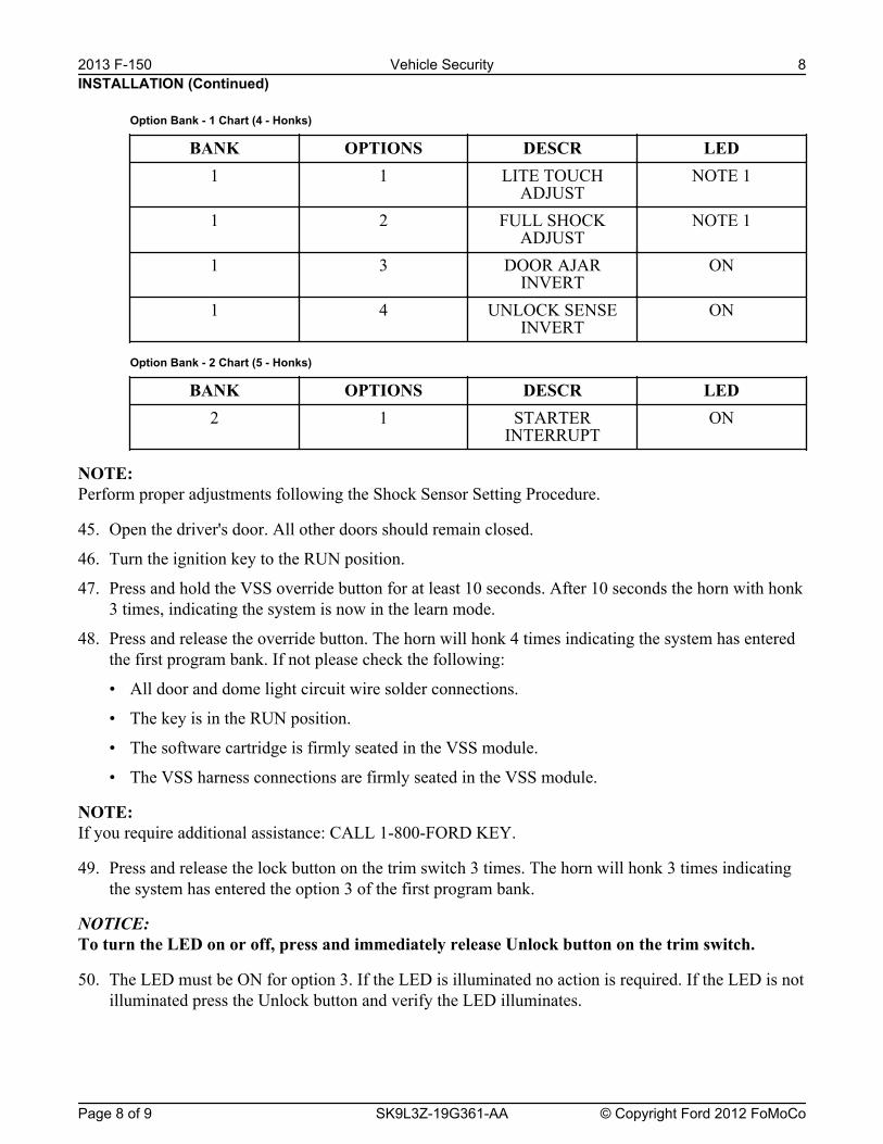
Option Bank - 1 Chart (4 - Honks)
BANK OPTIONS DESCR LED1 1 LITE TOUCH
ADJUSTNOTE 1
1 2 FULL SHOCKADJUST
NOTE 1
1 3 DOOR AJARINVERT
ON
1 4 UNLOCK SENSEINVERT
ON
Option Bank - 2 Chart (5 - Honks)
BANK OPTIONS DESCR LED2 1 STARTER
INTERRUPTON
NOTE: Perform proper adjustments following the Shock Sensor Setting Procedure.
45. Open the driver's door. All other doors should remain closed.
46. Turn the ignition key to the RUN position.
47. Press and hold the VSS override button for at least 10 seconds. After 10 seconds the horn with honk3 times, indicating the system is now in the learn mode.
48. Press and release the override button. The horn will honk 4 times indicating the system has enteredthe first program bank. If not please check the following:
• All door and dome light circuit wire solder connections.
• The key is in the RUN position.
• The software cartridge is firmly seated in the VSS module.
• The VSS harness connections are firmly seated in the VSS module.
NOTE: If you require additional assistance: CALL 1-800-FORD KEY.
49. Press and release the lock button on the trim switch 3 times. The horn will honk 3 times indicatingthe system has entered the option 3 of the first program bank.
NOTICE: To turn the LED on or off, press and immediately release Unlock button on the trim switch.
50. The LED must be ON for option 3. If the LED is illuminated no action is required. If the LED is notilluminated press the Unlock button and verify the LED illuminates.
INSTALLATION (Continued)2013 F-150 Vehicle Security 8
Page 8 of 9 SK9L3Z-19G361-AA © Copyright Ford 2012 FoMoCo
When programming the VSS module, if the Lock button is held for more than 3 seconds, the horn willhonk 4 times indicating the system returned to the factory default settings. If this occurs, return to step 1of the programming section to reprogram the remote start module.
51. Press and release the lock button on the trim switch. The horn will honk 4 times indicating thesystem has entered the option 4 of the first program bank.
52. The LED must be ON for option 4. If the LED is illuminated no action is required. If the LED is notilluminated press the unlock button and verify the LED illuminates.
53. Press and release the override button. The horn will honk 5 times indicating the system has enteredthe second option bank.
54. Press and release the Lock button on the trim switch. The horn will honk 1 time indicating thesystem has entered the option 1 of the second program bank.
55. The LED must be ON for option 1. If the LED is illuminated no action is required. If the LED is notilluminated press the unlock button and verify the LED illuminates.
56. The VSS module is now programmed.
INSTALLATION (Continued)
NOTE:
2013 F-150 Vehicle Security 9
Page 9 of 9 SK9L3Z-19G361-AA © Copyright Ford 2012 FoMoCo
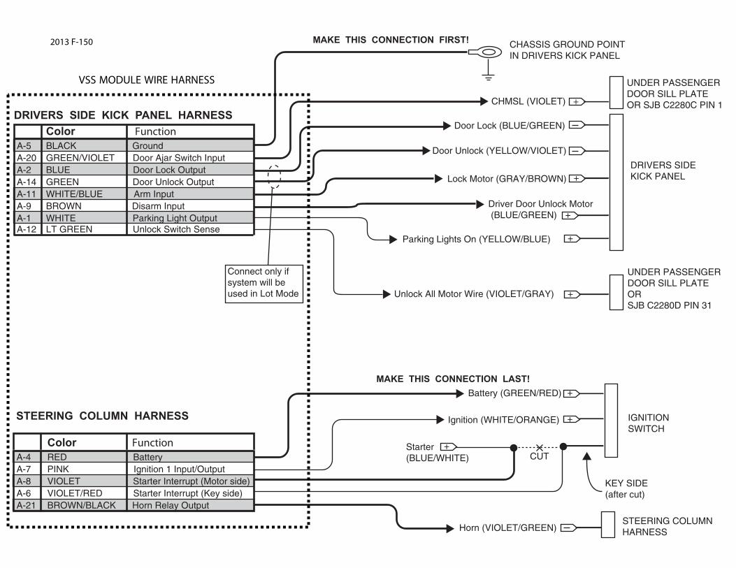
Color FunctionA-5 BLACK GroundA-20 GREEN/VIOLET Door Ajar Switch InputA-2 BLUE Door Lock Output A-14 GREEN Door Unlock OutputA-11 WHITE/BLUE Arm Input A-9 BROWN Disarm InputA-1 WHITE Parking Light OutputA-12 LT GREEN Unlock Switch Sense
DRIVERS SIDE KICK PANEL HARNESS
CHASSIS GROUND POINTIN DRIVERS KICK PANEL
MAKE THIS CONNECTION FIRST!
DRIVERS SIDEKICK PANEL
CHMSL (VIOLET) +
+
+
Door Lock (BLUE/GREEN)
Door Unlock (YELLOW/VIOLET)
Lock Motor (GRAY/BROWN)
Driver Door Unlock Motor (BLUE/GREEN)
+Unlock All Motor Wire (VIOLET/GRAY)
Color FunctionA-4 RED BatteryA-7 PINK Ignition 1 Input/OutputA-8 VIOLET Starter Interrupt (Motor side)A-6 VIOLET/RED Starter Interrupt (Key side)A-21 BROWN/BLACK Horn Relay Output
IGNITIONSWITCH
Battery (GREEN/RED)
Starter(BLUE/WHITE)
Ignition (WHITE/ORANGE)
STEERING COLUMNHARNESSHorn (VIOLET/GREEN)
STEERING COLUMN HARNESS
+
+
+
CUT
KEY SIDE(after cut)
MAKE THIS CONNECTION LAST!
Connect only if system will be used in Lot Mode
UNDER PASSENGERDOOR SILL PLATEOR SJB C2280C PIN 1
+Parking Lights On (YELLOW/BLUE)
VSS MODULE WIRE HARNESS
UNDER PASSENGERDOOR SILL PLATE ORSJB C2280D PIN 31
2013 F-150

Manual Table of Contents
VSS SYSTEM INSTALLATIONCONTENTS
INSTALLATIONVSS
GENERAL PROCEDURES Proper Splicing Techniques Programming Shock Sensor Setting WIRING DIAGRAMS Vehicle Specific Wiring Diagrams
Vehicle Security
Contents SK9L3Z-19G361-AA © Copyright Ford 2012 FoMoCo
2013 F-Super Duty
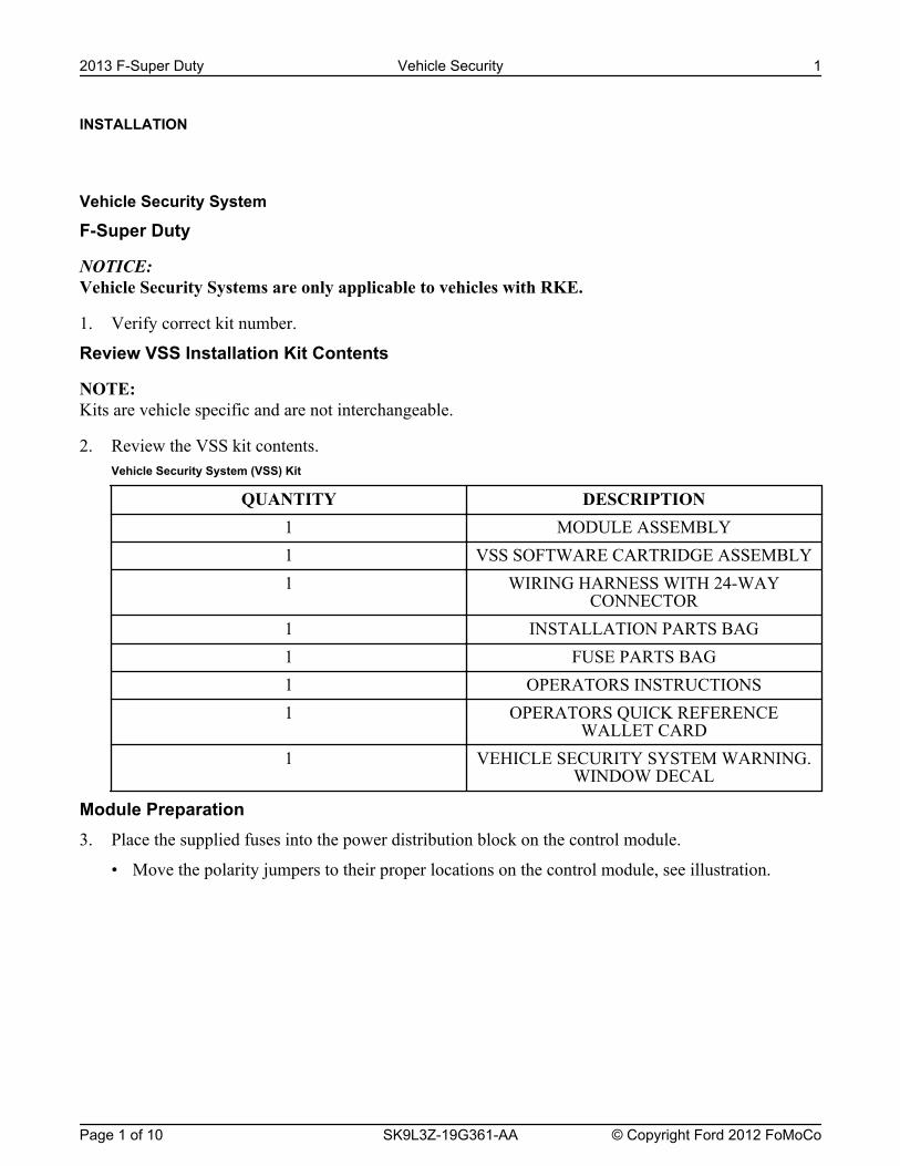
INSTALLATION
Vehicle Security System
F-Super Duty
NOTICE: Vehicle Security Systems are only applicable to vehicles with RKE.
1. Verify correct kit number.
Review VSS Installation Kit Contents
NOTE: Kits are vehicle specific and are not interchangeable.
2. Review the VSS kit contents.Vehicle Security System (VSS) Kit
QUANTITY DESCRIPTION1 MODULE ASSEMBLY1 VSS SOFTWARE CARTRIDGE ASSEMBLY1 WIRING HARNESS WITH 24-WAY
CONNECTOR1 INSTALLATION PARTS BAG1 FUSE PARTS BAG1 OPERATORS INSTRUCTIONS1 OPERATORS QUICK REFERENCE
WALLET CARD1 VEHICLE SECURITY SYSTEM WARNING.
WINDOW DECAL
Module Preparation3. Place the supplied fuses into the power distribution block on the control module.
• Move the polarity jumpers to their proper locations on the control module, see illustration.
2013 F-Super Duty Vehicle Security 1
Page 1 of 10 SK9L3Z-19G361-AA © Copyright Ford 2012 FoMoCo
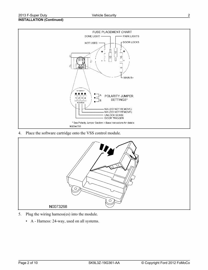
4. Place the software cartridge onto the VSS control module.
5. Plug the wiring harness(es) into the module.
• A - Harness: 24-way, used on all systems.
INSTALLATION (Continued)2013 F-Super Duty Vehicle Security 2
Page 2 of 10 SK9L3Z-19G361-AA © Copyright Ford 2012 FoMoCo
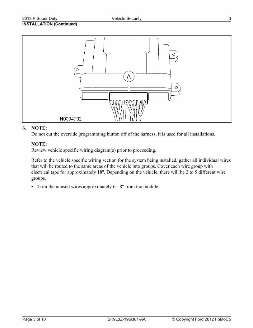
6. NOTE: Do not cut the override programming button off of the harness, it is used for all installations.
NOTE: Review vehicle specific wiring diagram(s) prior to proceeding.
Refer to the vehicle specific wiring section for the system being installed, gather all individual wiresthat will be routed to the same areas of the vehicle into groups. Cover each wire group withelectrical tape for approximately 18''. Depending on the vehicle, there will be 2 to 5 different wiregroups.
• Trim the unused wires approximately 6 - 8'' from the module.
INSTALLATION (Continued)2013 F-Super Duty Vehicle Security 3
Page 3 of 10 SK9L3Z-19G361-AA © Copyright Ford 2012 FoMoCo
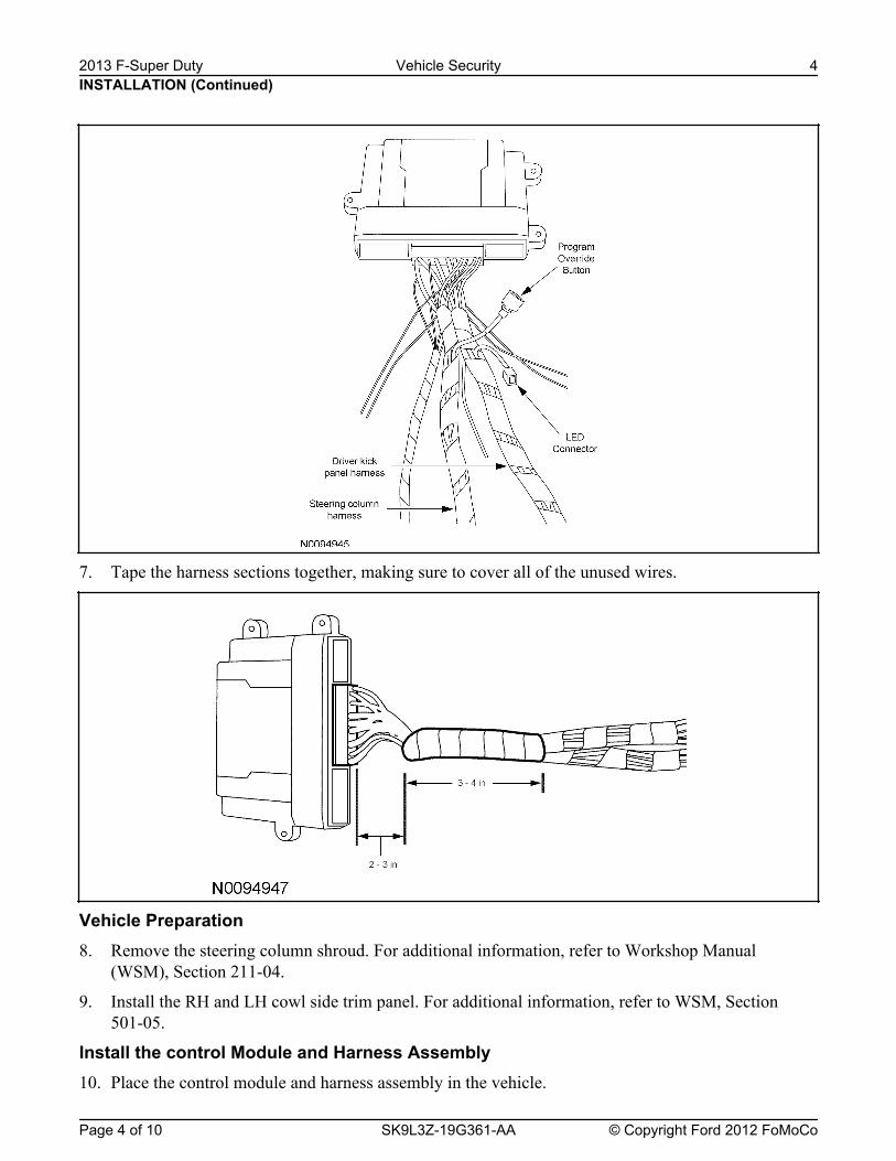
7. Tape the harness sections together, making sure to cover all of the unused wires.
Vehicle Preparation8. Remove the steering column shroud. For additional information, refer to Workshop Manual
(WSM), Section 211-04.
9. Install the RH and LH cowl side trim panel. For additional information, refer to WSM, Section501-05.
Install the control Module and Harness Assembly10. Place the control module and harness assembly in the vehicle.
INSTALLATION (Continued)2013 F-Super Duty Vehicle Security 4
Page 4 of 10 SK9L3Z-19G361-AA © Copyright Ford 2012 FoMoCo
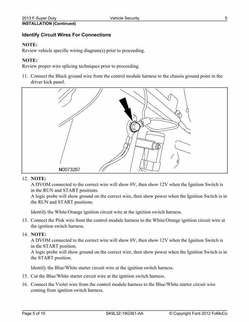
Identify Circuit Wires For Connections
NOTE: Review vehicle specific wiring diagram(s) prior to proceeding.
NOTE: Review proper wire splicing techniques prior to proceeding.
11. Connect the Black ground wire from the control module harness to the chassis ground point in thedriver kick panel.
12. NOTE: A DVOM connected to the correct wire will show 0V, then show 12V when the Ignition Switch isin the RUN and START positions.A logic probe will show ground on the correct wire, then show power when the Ignition Switch is inthe RUN and START positions.
Identify the White/Orange ignition circuit wire at the ignition switch harness.
13. Connect the Pink wire from the control module harness to the White/Orange ignition circuit wire atthe ignition switch harness.
14. NOTE: A DVOM connected to the correct wire will show 0V, then show 12V when the Ignition Switch isin the START position.A logic probe will show ground on the correct wire, then show power when the Ignition Switch is inthe START position.
Identify the Blue/White starter circuit wire at the ignition switch harness.
15. Cut the Blue/White starter circuit wire at the ignition switch harness.
16. Connect the Violet wire from the control module harness to the Blue/White starter circuit wirecoming from ignition switch harness.
INSTALLATION (Continued)2013 F-Super Duty Vehicle Security 5
Page 5 of 10 SK9L3Z-19G361-AA © Copyright Ford 2012 FoMoCo
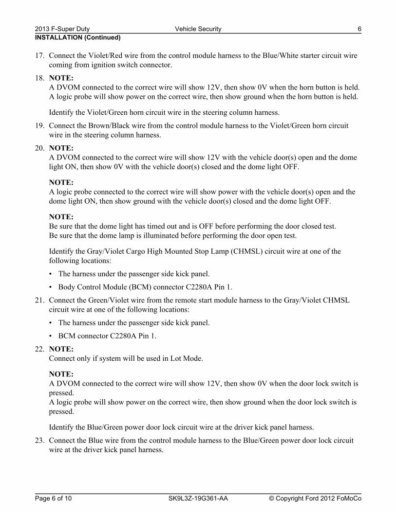
17. Connect the Violet/Red wire from the control module harness to the Blue/White starter circuit wirecoming from ignition switch connector.
18. NOTE: A DVOM connected to the correct wire will show 12V, then show 0V when the horn button is held.A logic probe will show power on the correct wire, then show ground when the horn button is held.
Identify the Violet/Green horn circuit wire in the steering column harness.
19. Connect the Brown/Black wire from the control module harness to the Violet/Green horn circuitwire in the steering column harness.
20. NOTE: A DVOM connected to the correct wire will show 12V with the vehicle door(s) open and the domelight ON, then show 0V with the vehicle door(s) closed and the dome light OFF.
NOTE: A logic probe connected to the correct wire will show power with the vehicle door(s) open and thedome light ON, then show ground with the vehicle door(s) closed and the dome light OFF.
NOTE: Be sure that the dome light has timed out and is OFF before performing the door closed test.Be sure that the dome lamp is illuminated before performing the door open test.
Identify the Gray/Violet Cargo High Mounted Stop Lamp (CHMSL) circuit wire at one of thefollowing locations:
• The harness under the passenger side kick panel.
• Body Control Module (BCM) connector C2280A Pin 1.
21. Connect the Green/Violet wire from the remote start module harness to the Gray/Violet CHMSLcircuit wire at one of the following locations:
• The harness under the passenger side kick panel.
• BCM connector C2280A Pin 1.
22. NOTE: Connect only if system will be used in Lot Mode.
NOTE: A DVOM connected to the correct wire will show 12V, then show 0V when the door lock switch ispressed.A logic probe will show power on the correct wire, then show ground when the door lock switch ispressed.
Identify the Blue/Green power door lock circuit wire at the driver kick panel harness.
23. Connect the Blue wire from the control module harness to the Blue/Green power door lock circuitwire at the driver kick panel harness.
INSTALLATION (Continued)2013 F-Super Duty Vehicle Security 6
Page 6 of 10 SK9L3Z-19G361-AA © Copyright Ford 2012 FoMoCo

NOTE: A DVOM connected to the correct wire will show 12V, then show 0V when the door unlock switchis pressed.A logic probe will show power on the correct wire, then show ground when the door unlock switchis pressed.
Identify the Yellow/Violet power door unlock circuit wire at the driver kick panel harness.
25. Connect the Green wire from the control module harness to the Yellow/Violet power door unlockcircuit wire at the driver kick panel harness.
26. NOTE: A DVOM connected to the correct wire will show 0V, then show 12V when the door lock switch ispressed.A logic probe will show ground on the correct wire, then show power when the door lock switch ispressed.
Identify the Gray/Brown power door lock motor circuit wire at the driver kick panel harness.
27. Connect the White/Blue wire from the control module harness to the Gray/Brown power door lockmotor circuit wire at the driver kick panel harness.
28. NOTE: A DVOM connected to the correct wire will show 0V, then show 12V when the driver door unlockswitch is pressed.A logic probe will show ground on the correct wire, then show power when the driver door unlockswitch is pressed.
Identify the Blue/Green driver power door unlock motor circuit wire at the driver kick panelharness.
29. Connect the Brown wire from the control module harness to the Blue/Green power door unlockmotor circuit wire at the driver kick panel harness.
30. NOTE: A DVOM connected to the correct wire will show 12V with the switch in the ON position and 0Vwith the switch in the parking lights OFF position.A logic probe connected to the correct wire will show power with the switch in the ON position andopen with the switch in the parking lights OFF position.
Identify the Yellow/Green parking light circuit wire at one of the following locations:
• The harness under the driver side kick panel.
• BCM connector C2280D Pin 18.
31. Connect the White wire from the control module harness to the Yellow/Green parking light wire atone of the following locations:
• The harness under the driver side kick panel.
• BCM connector C2280D Pin 18.
INSTALLATION (Continued)
24. NOTE: Connect only if system will be used in Lot Mode.
2013 F-Super Duty Vehicle Security 7
Page 7 of 10 SK9L3Z-19G361-AA © Copyright Ford 2012 FoMoCo
A DVOM connected to the correct wire will show 0V, then show 12V when the door unlock switchis pressed.A logic probe will show ground on the correct wire, then show power when the door unlock switchis pressed.
Identify the Violet/Gray power door unlock motor circuit wire at one of the following locations:
• The harness under the passenger side kick panel.
• BCM connector C2280D Pin 31.
33. Connect the Light Green wire from the control module harness to the Violet/Gray power doorunlock motor circuit wire at one of the following locations:
• The harness under the passenger side kick panel.
• BCM connector C2280D Pin 31.
Power Connection34. NOTE:
A DVOM connected to the correct wire will show 12V with the key in any position.A logic probe will show power on the correct wire with the key in any position.
Identify the Green/Red Battery circuit wire in the ignition switch harness.
35. Connect the Red wire from the control module harness to the Green/Red Battery circuit wire in theignition switch harness.
Program The VSS System36. Refer to the VSS programming section for this vehicle.
Secure VSS Harness and Control Module37. Use the supplied tie wraps to secure the VSS harness wires.
38. NOTE: Do not mount the control module in the knee bolster area.To ensure the best performance of the built-in shock sensor, secure the control module at threepoints to the vehicle.
Use the supplied long tie wraps to mount the VSS control module to the underdash wiring harness.
Install Trim39. Install the RH and LH cowl side trim panel. For additional information, refer to WSM, Section
501-05.
40. Install the steering column shroud. For additional information, refer to WSM, Section 211-04.
Programming the Module41. NOTE:
The LED on the VSS harness must be visible to complete module programming.
NOTE: The VSS override button must be accessible.
INSTALLATION (Continued)32. NOTE:
2013 F-Super Duty Vehicle Security 8
Page 8 of 10 SK9L3Z-19G361-AA © Copyright Ford 2012 FoMoCo
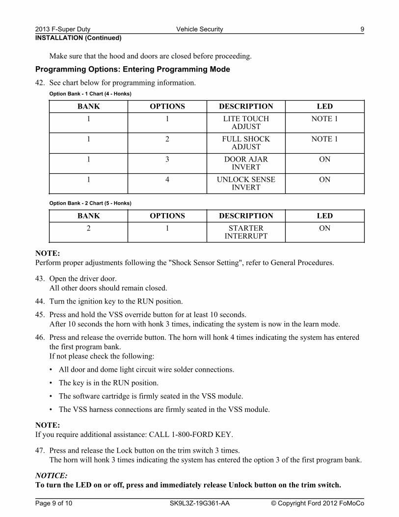
Make sure that the hood and doors are closed before proceeding.
Programming Options: Entering Programming Mode42. See chart below for programming information.
Option Bank - 1 Chart (4 - Honks)
BANK OPTIONS DESCRIPTION LED1 1 LITE TOUCH
ADJUSTNOTE 1
1 2 FULL SHOCKADJUST
NOTE 1
1 3 DOOR AJARINVERT
ON
1 4 UNLOCK SENSEINVERT
ON
Option Bank - 2 Chart (5 - Honks)
BANK OPTIONS DESCRIPTION LED2 1 STARTER
INTERRUPTON
NOTE: Perform proper adjustments following the "Shock Sensor Setting", refer to General Procedures.
43. Open the driver door.All other doors should remain closed.
44. Turn the ignition key to the RUN position.
45. Press and hold the VSS override button for at least 10 seconds.After 10 seconds the horn with honk 3 times, indicating the system is now in the learn mode.
46. Press and release the override button. The horn will honk 4 times indicating the system has enteredthe first program bank.If not please check the following:
• All door and dome light circuit wire solder connections.
• The key is in the RUN position.
• The software cartridge is firmly seated in the VSS module.
• The VSS harness connections are firmly seated in the VSS module.
NOTE: If you require additional assistance: CALL 1-800-FORD KEY.
47. Press and release the Lock button on the trim switch 3 times.The horn will honk 3 times indicating the system has entered the option 3 of the first program bank.
NOTICE: To turn the LED on or off, press and immediately release Unlock button on the trim switch.
INSTALLATION (Continued)2013 F-Super Duty Vehicle Security 9
Page 9 of 10 SK9L3Z-19G361-AA © Copyright Ford 2012 FoMoCo

48. The LED must be ON for option 3. If the LED is illuminated no action is required. If the LED is notilluminated press the Unlock button and verify the LED illuminates.
NOTE: When programming the VSS module, if the Lock button is held for more than 3 seconds, the horn willhonk 4 times indicating the system returned to the factory default settings. If this occurs, return to step 1of the programming section to reprogram the VSS module.
49. Press and release the Lock button on the trim switch.The horn will honk 4 times indication the system has entered the option 4 of the first program bank.
50. The LED must be ON for option 4. If the LED is illuminated no action is required. If the LED is notilluminated press the unlock button and verify the LED illuminates.
51. Press and release the override button. The horn will honk 5 times indicating the system has enteredthe second option bank.
52. Press and release the Lock button on the trim switch.The horn will honk 1 time indication the system has entered the option 1 of the second programbank.
53. The LED must be ON for option 1. If the LED is illuminated no action is required. If the LED is notilluminated press the Unlock button and verify the LED illuminates.
54. The VSS module is now programmed.
INSTALLATION (Continued)2013 F-Super Duty Vehicle Security 10
Page 10 of 10 SK9L3Z-19G361-AA © Copyright Ford 2012 FoMoCo
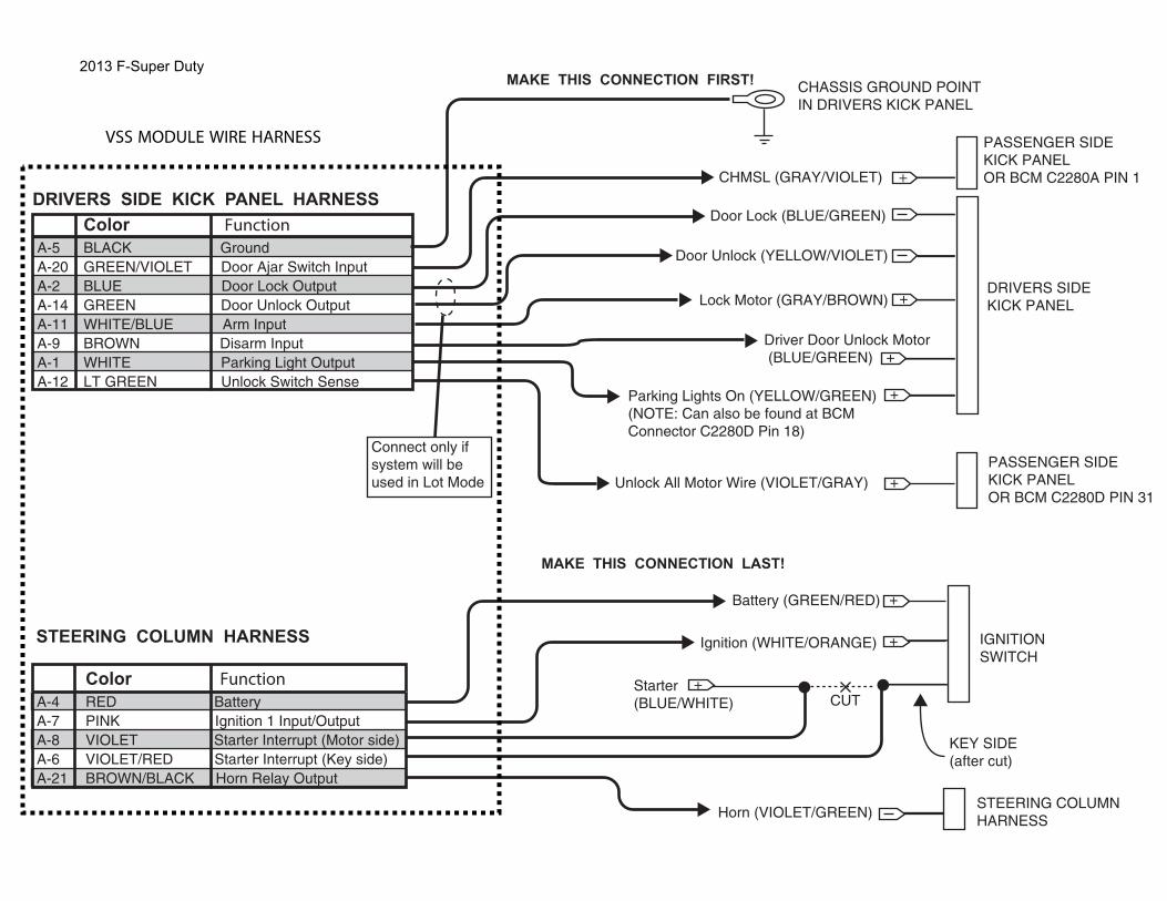
Color FunctionA-5 BLACK GroundA-20 GREEN/VIOLET Door Ajar Switch InputA-2 BLUE Door Lock Output A-14 GREEN Door Unlock OutputA-11 WHITE/BLUE Arm Input A-9 BROWN Disarm InputA-1 WHITE Parking Light OutputA-12 LT GREEN Unlock Switch Sense
DRIVERS SIDE KICK PANEL HARNESS
CHASSIS GROUND POINTIN DRIVERS KICK PANEL
MAKE THIS CONNECTION FIRST!
DRIVERS SIDEKICK PANEL
CHMSL (GRAY/VIOLET) +
+
+
Door Lock (BLUE/GREEN)
Door Unlock (YELLOW/VIOLET)
Lock Motor (GRAY/BROWN)
Driver Door Unlock Motor (BLUE/GREEN)
+Unlock All Motor Wire (VIOLET/GRAY)
Color FunctionA-4 RED BatteryA-7 PINK Ignition 1 Input/OutputA-8 VIOLET Starter Interrupt (Motor side)A-6 VIOLET/RED Starter Interrupt (Key side)A-21 BROWN/BLACK Horn Relay Output
IGNITIONSWITCH
Battery (GREEN/RED)
Starter(BLUE/WHITE)
Ignition (WHITE/ORANGE)
STEERING COLUMNHARNESSHorn (VIOLET/GREEN)
STEERING COLUMN HARNESS
+
+
+
CUT
KEY SIDE(after cut)
MAKE THIS CONNECTION LAST!
Connect only if system will be used in Lot Mode
PASSENGER SIDEKICK PANELOR BCM C2280A PIN 1
+Parking Lights On (YELLOW/GREEN)(NOTE: Can also be found at BCM Connector C2280D Pin 18)
VSS MODULE WIRE HARNESS
PASSENGER SIDEKICK PANELOR BCM C2280D PIN 31
2013 F-Super Duty