Embed Size (px)
Citation preview
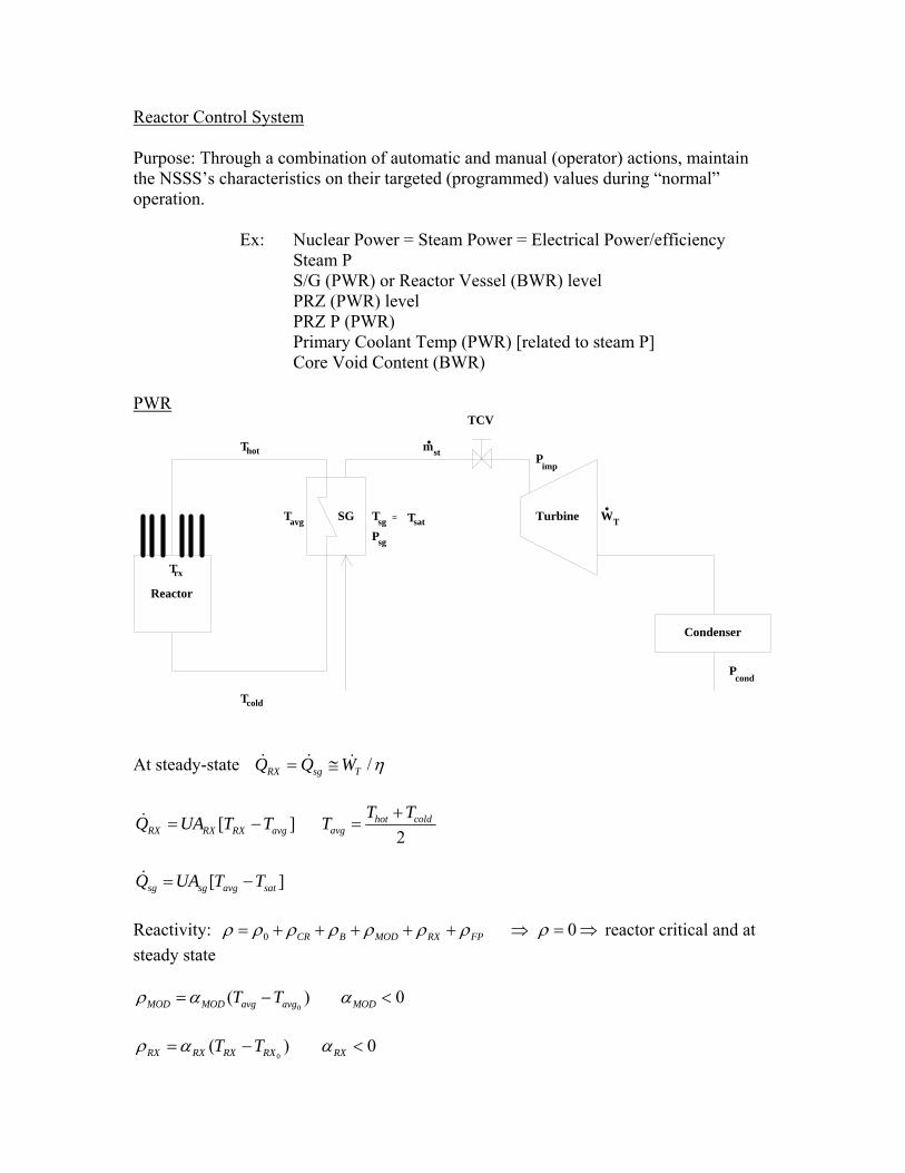
Reactor Control System Purpose: Through a combination of automatic and manual (operator) actions, maintain the NSSS’s characteristics on their targeted (programmed) values during “normal” operation. Ex: Nuclear Power = Steam Power = Electrical Power/efficiency Steam P S/G (PWR) or Reactor Vessel (BWR) level PRZ (PWR) level PRZ P (PWR) Primary Coolant Temp (PWR) [related to steam P] Core Void Content (BWR) PWR
Reactor
SG Turbine
Condenser
T
T
T
P
T
P
P
WT
T
TCV
hot
cold
avg
rx
sg sat
sg
cond
T
imp
=
stm
At steady-state /RX sg TQ Q W
[ ]RX RX RX avgQ UA T T 2
hot coldavg
T TT
[ ]sg sg avg satQ UA T T
Reactivity: 0 CR B MOD RX FP 0 reactor critical and at
steady state
0( )MOD MOD avg avgT T 0MOD
0( )RX RX RX RXT T 0RX

“NATURAL” RESPONSE TO POWER MANEUVERS
Power maneuvers are typically initiated by actions on the steam side. What is the “Natural” system response (no automatic control operations) to perturbations initiated on the secondary (steam) side?
Reactor
SG Turbine
Condenser
T
T
T
P
T
P
P
WT
T
TCV
hot
cold
avg
rx
sg sat
sg
cond
T
imp
=
stm
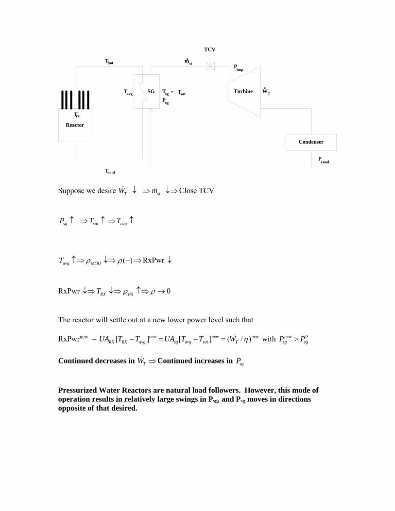
Suppose we desire T stW m Open TCV
sg satP T
If sgUA constant (UTUBE) avgT
( )avg MODT RxPwr
RxPwr 0RX RXT
The reactor will settle out at a new higher power level such that RxPwrnew = [ ] [ ] ( / )new new new
RX RX avg sg avg sat TUA T T UA T T W with 0newsg sgP P
Continued increases in TW Continued decreases in sgP
Reactor
SG Turbine
Condenser
T
T
T
P
T
P
P
WT
T
TCV
hot
cold
avg
rx
sg sat
sg
cond
T
imp
=
stm
Suppose we desire T stW m Close TCV
sg satP T avgT
( )avg MODT RxPwr
RxPwr 0RX RXT
The reactor will settle out at a new lower power level such that RxPwrnew = [ ] [ ] ( / )new new new
RX RX avg sg avg sat TUA T T UA T T W with 0newsg sgP P
Continued decreases in TW Continued increases in sgP
Pressurized Water Reactors are natural load followers. However, this mode of operation results in relatively large swings in Psg, and Psg moves in directions opposite of that desired.

Suppose we wish to keep Psg approximately constant over the entire power range.
Reactor
SG Turbine
Condenser
T
T
T
P
T
P
P
WT
T
TCV
hot
cold
avg
rx
sg sat
sg
cond
T
imp
=
stm
T stW m Open TCV however, require sg satP T and impP
[ ]
sgQ
sg avg satst
g fd
UA T Tm
h h
For h and sat st avgT m T
( )avg MODT
In addition [ ]sg RX RX RX avg RXQ Q UA T T T
( )RX RXT
To maintain Psg constant at higher powers implies negative reactivity which must be compensated for. Solution Withdraw control rods.

Reactor
SG Turbine
Condenser
T
T
T
P
T
P
P
WT
T
TCV
hot
cold
avg
rx
sg sat
sg
cond
T
imp
=
stm
Similarly if we desire T stW m Close TCV impP
[ ]
sgQ
sg avg satst
g fd
UA T Tm
h h
For h and sat st avgT m T
( )avg MODT
In addition [ ]sg RX RX RX avg RXQ Q UA T T T
( )RX RXT
To maintain Psg constant at lower powers implies positive reactivity which must be compensated for. Solution Insert control rods.

CONTROLLING Tavg IMPLIES CONTROLLING Psg
Pro
gram
med
Tav
g
Electrical Power0 % 100 %
The Tavg program is chosen based on PRZ size and steam P considerations.
where ( )sg AVG sat sat Sat SGSGQ UA T T T T P
Given avgT and /RX sg TQ Q W T across S/G Fixed satT of steam fixed
SGP fixed
In OTSGs, SGQ while holding both Tavg and Tsat constant can be accomplished by
changing the steam generator level (UA). However, TRX still as before requiring control rod motion.

PWR: Nuclear Power
Electrical Power Turbine Impulse Pressure Reactor Power ( relP )
Core Av. Coolant Temp. AvgT
Turbine Impulse Pressure (psia)
0 200 400 600 800 1000
Rel
ativ
e P
ower
(%
)
0
20
40
60
80
100
120
Reactor PowerElectrical Power
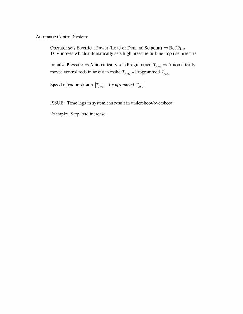
Automatic Control System: Operator sets Electrical Power (Load or Demand Setpoint) Ref Pimp
TCV moves which automatically sets high pressure turbine impulse pressure
Impulse Pressure Automatically sets Programmed AVGT Automatically
moves control rods in or out to make AVGT Programmed AVGT
Speed of rod motion AVG AVGT Programmed T
ISSUE: Time lags in system can result in undershoot/overshoot Example: Step load increase


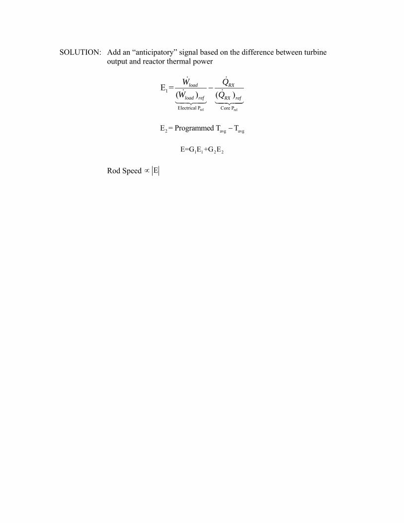
SOLUTION: Add an “anticipatory” signal based on the difference between turbine output and reactor thermal power
rel rel
1
Electrical P Core P
E =( ) ( )
load RX
load ref RX ref
W Q
W Q
2 avg avgE = Programmed T T
1 1 2 2E=G E +G E
Rod Speed E


What if control rods result in undesirable positions? Ex: Totally withdrawn Cannot withdraw anymore
Too deep inserted Violating control rods insertion limits not enough rod
worth to trip plant to required subcritical condition Power shape violates power peaking limits, e.g. F or QF .
How are rods repositioned? Change soluble boron concentration in the primary loop!
Rods too inserted Borate Rods too withdrawn Dilute
How much should PPM be changed?
0 1 0 1rodsPPM PPM Position Position

Special situation of rapid load reduction
Electrical relP (with time) rapidly AVG AVG
rel rel
T Programmed T
Core P Electrical P
rapidly
Control rods insert Core relP
Problem: Control rods don’t insert fast enough Core relP Electrical relP
AVGT continues AVGT Programmed AVGT .
What happens to steam P?
Electrical relP rapidly
AVG
Turbine control valves partially close
T
Steam P
Automatic Control System Actions
Rapid decrease in Electrical AVG
rel
T
P
Steam P
Control rods inserted
Core relP
Core relP but Core relP ElectricalAVG
rel
T
P continues
Steam P
AVG AVG Set Point
Set Point
T Programmed T ΔT
Steam P > Steam P
If
Open Steam Dump (Turbine Bypass)
Valves Blow Steam (to condenser or atmosphere) Steam P . Steam Temp SG AVGΔT T …Steam dump valves stay open until setpoint
values not exceeded.

Feedwater Pump Speed Control
F/W Pump
Feed Control ValveSteam Generator
Turbine Control Valve
High Pressure TurbineRCS Flow
PressureP
P P
f/w
steamImpulse
Typical Pump Curve
P
G
RPM
p
RPM 1
RPM 2
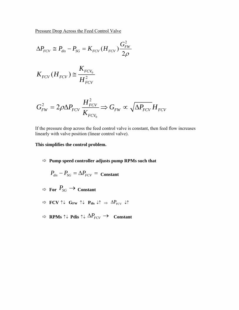
Pressure Drop Across the Feed Control Valve
2
( )2
FWFCV dis SG FCV FCV
GP P P K H
0
2( )
FCV
FCV FCVFCV
KK H
H
0
22 2 FCVFW FCV FW FCV FCV
FCV
HG P G P H
K
If the pressure drop across the feed control valve is constant, then feed flow increases linearly with valve position (linear control valve). This simplifies the control problem. Pump speed controller adjusts pump RPMs such that
dis SG FCVP P P Constant
For SGP Constant
FCV GFW Pdis FCVP
RPMs Pdis FCVP Constant

Turbine Control
P Psteam impulse
Turbine Control Valve
Pimpulse Controller
Set Elec. Prel Set Prog. impulse impulse impulseP P Prog P 0 Close
down on turbine control valve impulseP
How is Prog impulseP determined?
Require RPMT/G = Prog. RPMT/G (1800 @ all Elec. Prel AC frequency) With fixed RPMT/G and Elec. Prel Pimpulse uniquely specified RPM Controller T/G T/GRPM Prog RPM 0 Close down on control valve
Pimpulse RPMT/G Error signal for T/G controller controls both impulseP and T/GRPM utilizing Turbine
Control Valves

S/G Level Control (UTUBE) Programmed level to assure S/G tubes covered to assure adequate heat transfer and separators not flooded.
Level %
Relative Power0 100 %
1. S/G level correct.
If Steam Mass Flow Rate = F/W Mass Flow Rate S/G level constant. If S/G level correct, adjust F/W Flow Rate such that it equals Steam Flow Rate. Adjustment done by valve and/or variable speed F/W Pump
2. S/G level not correct.
Adjust F/W Flow Rate to bring steam generator level to programmed value.
Issue: Load follow maneuver
Electrical relP Turbine Control Valves Open
Steam flow
Steam PsatT
Water in S/G Flashes S/G Level
“Swell” effect (short lived phenomena)
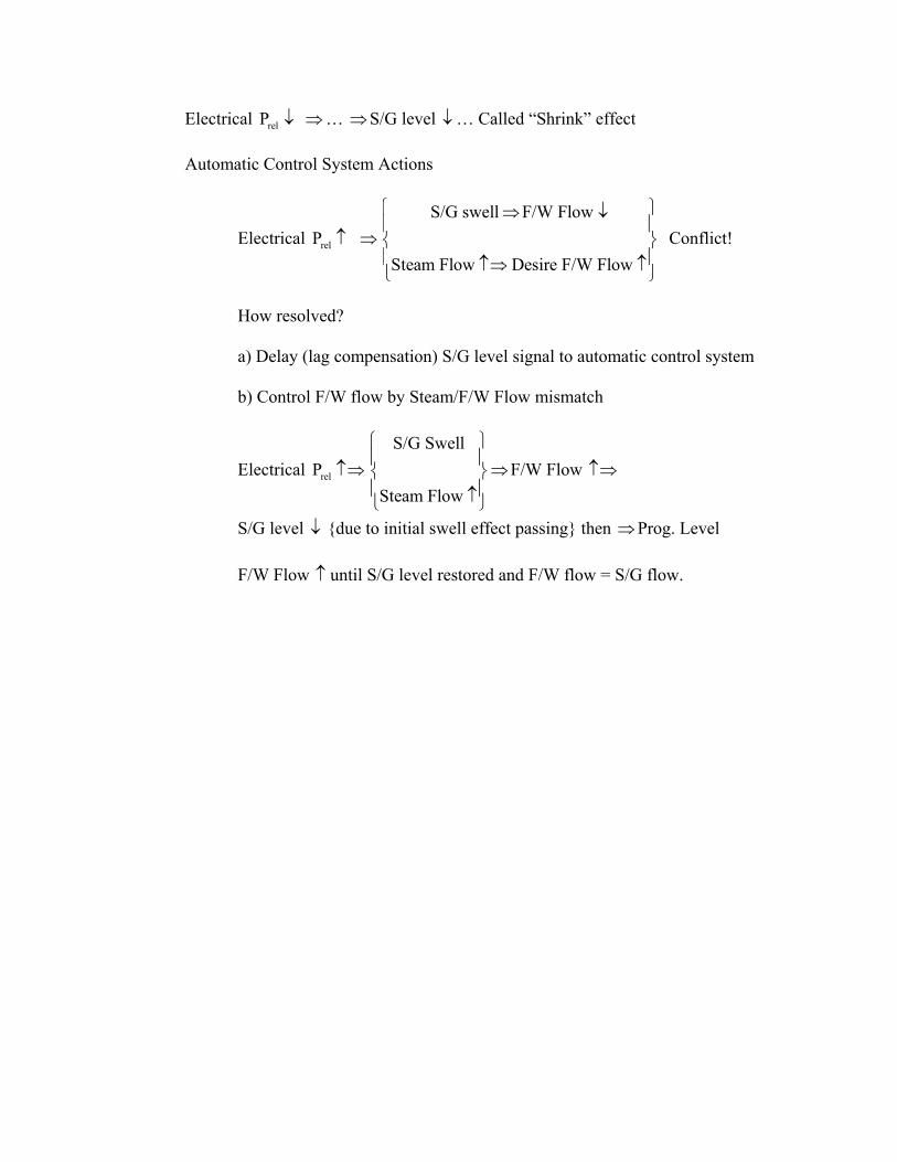
Electrical relP … S/G level … Called “Shrink” effect
Automatic Control System Actions
Electrical relP S/G swell F/W Flow
Steam Flow Desire F/W Flow
Conflict!
How resolved?
a) Delay (lag compensation) S/G level signal to automatic control system b) Control F/W flow by Steam/F/W Flow mismatch
Electrical relP S/G Swell
Steam Flow
F/W Flow
S/G level {due to initial swell effect passing} then Prog. Level F/W Flow until S/G level restored and F/W flow = S/G flow.
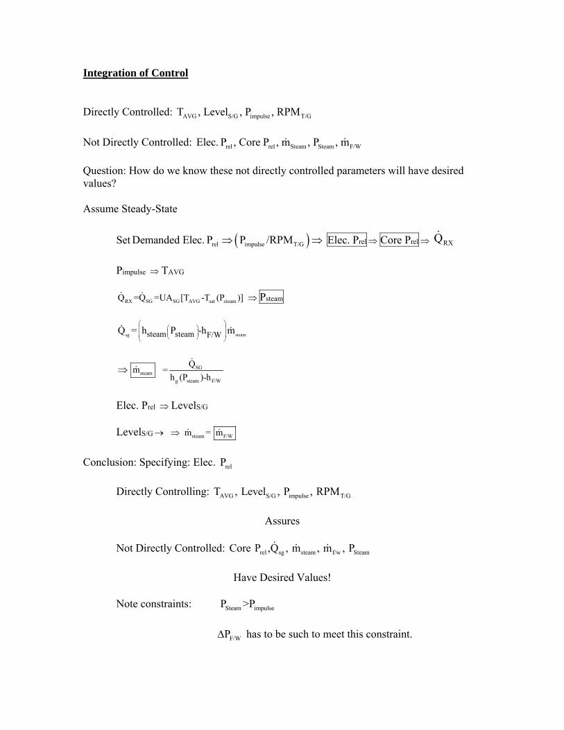
Integration of Control Directly Controlled: AVG S/G impulse T/GT , Level , P , RPM
Not Directly Controlled: rel rel Steam Steam F/WElec. P , Core P , m , P , m
Question: How do we know these not directly controlled parameters will have desired values? Assume Steady-State
Set rel impulse T/GDemanded Elec. P P /RPM Elec. Prel Core Prel RXQ
Pimpulse TAVG
RX SG SG AVG sat steamQ =Q =UA [T -T (P )] Psteam
sg steamsteam steam F/WQ = h P -h m
steamm SG
g steam F/W
Q=
h (P )-h
Elec. Prel LevelS/G
LevelS/G steam F/W m = m
Conclusion: Specifying: Elec. relP
Directly Controlling: AVG S/G impulse T/GT , Level , P , RPM
Assures
Not Directly Controlled: rel sg steam f/w SteamCore P ,Q , m , m , P
Have Desired Values!
Note constraints: Steam impulseP >P
F/WP has to be such to meet this constraint.

Response to Load Maneuver relElec. P Prog impulseP Turbine Control Valve Pimpulse
Turbine Control Valve steamP Steam S/G sgT T Q
AVG rel
AVG
T Core P
Prog. T Control Rods Insert
relCore P
When WR sg AVG Steam SteamCore P < Q T T P
steam lvl
steam
P SG then
TCV m
F/W Control Valves f/w m
Note: T/GRPM control is also required to assure relElec. P demanded satisfied
Indirectly control steamm to correct value.

Prz level
Electrical relP Programmed AVGT Primary loop Av. Water Density Primary Loop
Water Volume Unique Prz Level (Programmed Prz Level)
Prz level maintained by CVCS Prz level Prog. Prz level CVCS Charging Rate CVCS Letdown Rate.
Automatic Control System Tavg Programmed Prz. Level CVCS Rate dependent upon Prz. Level
Programmed Prz. Level When Tavg and Prz Level = Prog. Prz level CVCS Charging Rate = CVCS Letdown Rate.

Prz Pressure
Objective: Hold Primary System P constant set pointP
Assume SS operation P = set pointP
Prz Heaters on sufficient to offset heat losses from Prz and spray circulation (some to keep Prz chemistry same as rest of RCS & Minimize Thermal Shock)
Electrical relP ( ) AVGT ( ) initially Prz level ( ) Prz P ( )
Automatic Control System
(Prz P – PSet Point)
0 Prz Heaters Output
0 Prz Heaters Output
If (Prz P – PSet Point) Set Point(1)ΔP Prz Sprays Prz Steam Condenses Prz P
If (Prz P – PSet Point) Set Point (2) Set Point (1)ΔP >ΔP Prz Pilot Operated Relief Valve (PORV)
Opens Prz Steam blows down to Prz Relieve Tank Prz Pr If (Prz P – PSet Point) < Set Point(3)ΔP Backup Heaters On
Longer Term Effect:
rel AVG AVG AVGElec. P Prog. T T via T control ...