Embed Size (px)
Citation preview

June 27, 2005
PARTS LIST
ISSUED: March 8, 1999
REACH-INS
Reliability is abeautiful thingTM
REVISED:
SafeTemp Models
ITEM #: 71184
FH1-AAC(-HD)FH2-AAC(-HD)

2
CONTENTSMaterial Abbreviations ........................................................................................................... 4Auxiliary Codes ...................................................................................................................... 5Note About Ordering Parts .................................................................................................... 6A. Reach-In ............................................................................................................................ 7
FH1-AAC(-HD) .................................................................................................................. 7FH2-AAC(-HD) .................................................................................................................. 9
B. Refrigeration Assembly ................................................................................................... 11FH1-AAC(-HD) ................................................................................................................ 11FH2-AAC(-HD) ................................................................................................................ 13
C. Panel-Front Hinged Assembly ......................................................................................... 15FH1-AAC(-HD), FH2-AAC(-HD) ...................................................................................... 15
D. Body-Final ....................................................................................................................... 16FH1-AAC ......................................................................................................................... 16FH1-AAC-HD ................................................................................................................... 18FH2-AAC ......................................................................................................................... 20FH2-AAC-HD ................................................................................................................... 22
E. Control Box Assembly ..................................................................................................... 24FH1-AAC(-HD), FH2-AAC(-HD) ...................................................................................... 24
F. Fan-Evaporator Assembly ................................................................................................ 27FH1-AAC(-HD) ................................................................................................................ 27FH2-AAC(-HD) ................................................................................................................ 29
G. Evaporator Assembly ...................................................................................................... 30FH1-AAC(-HD) ................................................................................................................ 30FH2-AAC(-HD) ................................................................................................................ 32
H. Condenser Assembly ...................................................................................................... 34FH1-AAC(-HD) ................................................................................................................ 34FH2-AAC(-HD) ................................................................................................................ 36
J. Body-Prefinal ................................................................................................................... 37FH1-AAC(-HD) ................................................................................................................ 37FH2-AAC(-HD) ................................................................................................................ 39
K. Door-Right ....................................................................................................................... 41FH1-AAC, FH2-AAC ........................................................................................................ 41
L. Door-Left .......................................................................................................................... 42FH2-AAC ......................................................................................................................... 42
M. Door-Half (UR) ................................................................................................................ 43FH1-AAC-HD, FH2-AAC-HD ........................................................................................... 43
N. Door-Half (LR) ................................................................................................................. 44FH1-AAC-HD, FH2-AAC-HD ........................................................................................... 44
P. Door-Half (UL) .................................................................................................................. 45FH2-AAC-HD ................................................................................................................... 45
Q. Door-Half (LL) ................................................................................................................. 46FH2-AAC-HD ................................................................................................................... 46
R. Distributor-Air Top Assembly ........................................................................................... 47FH1-AAC-(HD) ................................................................................................................ 47

3
S. Mullion-Horizontal ............................................................................................................ 48FH1-AAC-HD ................................................................................................................... 48
T. Mullion-Vertical ................................................................................................................. 49FH2-AAC ......................................................................................................................... 49
U. Mullion-Cross .................................................................................................................. 51FH2-AAC-HD ................................................................................................................... 51
V. Label Location ................................................................................................................. 53FH1-AAC(-HD) ................................................................................................................ 53FH2-AAC(-HD) ................................................................................................................ 54
W. Literature & Packaging ................................................................................................... 55FH1-AAC(-HD), FH2-AAC(-HD) ...................................................................................... 55

4
Material AbbreviationsALUMINUM AL = Aluminum
COPPER CU = Copper
PLASTIC ABS = Acrylonitrile -butadiene - styrene AC = Polyacetal EVA = Ethylene vinyl acetate PA = Polyamide = Nylon PC = Polycarbonate PE = Polyethylene PES = Polyester PETP = Polyethylene terephthalate = Tetlon PP = Polypropylene PS = Polystyrene PTFE = Polytetrafluoroethylene = Teflon PUR = Polyurethane PVC = Polyvinyl chloride
RUBBER VN = Vinyl Nitrile EPDM = EP rubber NBR = Nitrile butadiene rubber NR = Natural rubber NP = Neoprene SI.R = Silicone rubber SY.R = Synthetic rubber EPH = Epichlorohydrin
STEEL GS = Galvanized steel SS = Stainless steel PS = Plated steel PAS = Primed steel
AUXILIARY CODEK-5 Designates the year. "K" indicates the year 2000. Years progress or regress in alphabetical order. "J" is 1999, "L" is 2001, "M" is 2002, and so on. The letters "I" and "O" were skipped. Designates significant part changes within the same year for this model. Base is 5 (0 for codes L-0 and earlier) and this number advances for each change.
Example: P-6 "P" indicates 2004. "6" indicates the first significant part change for 2004.

5
Auxiliary Codes
FH1-AAC K-0 October 2000 L-5 March 2001 M-5 January 2002 M-6 February 2002 M-7 July 2002 N-5 December 2002 N-6 January 2003 P-5 December 2003 P-6 March 2004 P-7 October 2004 P-8 November 2004 Q-5 December 2004 Q-6 June 2005
FH1-AAC-HD K-0 October 2000 L-0 November 2000 L-5 March 2001 M-5 January 2002 M-6 March 2002 M-7 July 2002 N-6 January 2003 P-5 February 2004 P-6 March 2004 Q-5 December 2004 Q-6 June 2005
FH2-AAC L-5 February 2001 M-5 January 2002 M-6 March 2002 M-7 July 2002 M-8 August 2002 N-5 December 2002 N-6 January 2003 P-5 December 2003 P-6 August 2004 P-7 November 2004 Q-5 December 2004 Q-6 June 2005

6
Auxiliary Codes FH2-AAC-HD K-0 August 2000 L-5 July 2001 M-6 March 2002 N-6 February 2003 P-5 January 2004 P-6 August 2004 P-7 October 2004 P-8 November 2004 Q-5 December 2004 Q-6 June 2005
Note About Ordering PartsMost assemblies cannot be ordered as complete units; parts in the assemblies generally must be ordered separately.

7
A. Reach-InFH1-AAC(-HD)
K-0, L-0, L-5, M-5, M-6, M-7, N-5, N-6, P-5, P-6, P-7, P-8, Q-5, Q-6
1a1
2a2
3a3 3b 3c 3d
11
67
7a
9a9
4a4
B B1 B2 B3
EE1
D
CC1
C2
C3
8a
8
10
1213
V
5a5

8
Title: A. Reach-In Model: FH1-AAC(-HD)
Index No. Description
Material or Model Number Part Number
Required Number
K-0 to
L-5
M-5 to
N-5
N-6 to
Q-6
B Refrigeration System Refrigerator 1A0524A01 1 1 1
B1 Bolt Assembly 8×45 437889-01 5 5 5
B2 Truss Head Screw 5×25, SS 7C32-0525 2 2 2
B3 Washer 5 7W22-0500 2 2 2
C Panel – Front Hinged Assembly - 3A1670A01 1 1 1
C1 Clevis Pin - 8907-0102 2 2 2
C2 Cotter Pin - 8907-0103 2 2 2
C3 Flat Washer - 4A0655-03 2 2 2
D Body – Final FH1-AAC 1A0299A05 1 1 1
FH1-AAC-HD 1A0360A03 1 1 1
E Control Box Assembly - 2A1842A03 1 1 1
E1 T2 Screw 4×8, SS 7P32-0408 3 3 3
V Label Location FH1-AAC 2A1042A09 1 1 1
FH1-AAC-HD 2A1042A08 1 1 1
1 Gusset – Frame GS 3A1520-01 1 1 -
4A2845-01 1
1a T2 Screw 4×8, SS 7P32-0408 4 4 4
2 Frame – Side Top GS 2A1803-01 2 2 2
2a Truss Head Screw 5×10, SS 7C32-0510 8 8 8
3 Panel – Side, Top AL 2A1800-21 2 2 2
3a Truss Head Screw 5×10, SS 7C32-0510 6 6 6
3b Taper Collar SS 4H0171-01 2 2 2
3c Screw Countersunk 5×20, SS 7C42-0520 2 2 2
3d T2 Screw 4×8, SS 7P32-0408 4 4 4
4 Cover UL Top GS 2A1304-01 1 -
2A2373-01 1 -
2A2755-01 1
4a T2 Screw 4×8, SS 7P32-0408 5 5 5
5 Cover – UL, Rear GS 2A0956-01 1 1 -
2A2752-01 1
5a T2 Screw 4×8, SS 7P32-0408 4 4 4
6 Power Cord - 4A0520-01 1 1 1
7 Wire Clamp - 4A0809-02 1 1 1
7a T2 Screw 4×8, SS 7P32-0408 1 1 1
8 Cover – Connector Wire GS 3A1678-01 1 1 1
8a T2 Screw 4×8, SS 7P32-0408 2 2 2
9 Cover – Wire GS 3A1679-01 1 1 1
9a T2 Screw 4×8, SS 7P32-0408 3 3 3
10 Bracket – Hinge GS 4A2306-01 2 2 2
11 Threaded Insert M5 4A0407-01 4 4 4
12 Spacer – Hinge PA 4A2473-01 2 2 2
13 Bracket – Control Box GS 4A2467-01 1 1 1

9
A. Reach-In FH2-AAC(-HD)
K-0, L-5, M-5, M-6, M-7, M-8, N-5, N-6, P-5, P-6, P-7, P-8, Q-5, Q-6
9 12
B B1 B2 B2
V
1a1
102a
2 1b
4a4
5a5
6 7 7a
11 11a
3a3 3b 3c 3d
D
EE1
13
CC1
C2
C38a8
9a

10
Title: A. Reach-In Model: FH2-AAC(-HD)
Index No. Description
Material or Model Number Part Number
Required Number
K-0 to
N-5
N-6 to
Q-6
B Refrigeration System - 1A0255A02 1 1
B1 Bolt Assembly 8×45 437889-01 6 6
B2 Hex Bolt 8×70 7B01-0870 2 2
B3 Washer 8 7W22-0800 2 2
C Panel – Front Hinged Assembly - 3A1670A02 1 1
C1 Clevis Pin - 8907-0102 2 2
C2 Cotter Pin - 8907-0103 2 2
C3 Flat Washer - 4A0655-03 2 2
D Body – Final FH2-AAC 2A1215A05 1 1
FH2-AAC-HD 1A0370A03 1 1
E Control Box Assembly - 2A1842A05 1 1
E1 T2 Screw 4×8, SS 7P32-0408 4 4
V Label Location FH2-AAC 3A0603G09 1 1
FH2-AAC-HD 3A0603G08 1 1
1 Gusset – Frame GS 3A1520-01 1 -
GS 4A2845-01 1
1a T2 Screw 4×8, SS 7P32-0408 2 2
1b Truss Head Screw 5×10, SS 7C32-0510 2 2
2 Frame – Side Top GS 2A1803-01 2 2
2a Truss Head Screw 5×10 7C32-0510 8 8
3 Panel – Side, Top AL 2A1800-21 2 2
3a Truss Head Screw 5×10, SS 7C32-0510 6 6
3b Taper Collar SS 4H0171-01 2 2
3c Countersunk Screw 5×20, SS 7C42-0520 2 2
3d T2 Screw 4×8, SS 7P32-0408 4 4
4 Top UL Cover GS 2A1118-03 1 1
4a T2 Screw 4×8, SS 7P32-0408 5 5
5 Rear UL Cover GS 2A1117-01 1 1
5a T2 Screw 4×8, SS 7P32-0408 5 5
6 Power Cord Set - 4A1543-01 1 1
7 Wire Clamp - 4A0809-03 1 1
7a Truss Head Screw 5×8, SS 7C32-0508 1 1
8 Cover – Wire GS 2A1861-01 1 1
8a T2 Screw 4×8 7P32-0408 3 3
9 Bracket – Hinge - 4A2306-01 2 2
9a Truss Head Screw 4×8 7C32-0408 2 2
10 Threaded Insert M5 4A0407-01 4 4
11 Distributor – Air Top - 1A0152-05 1 1
11a T2 Screw 4×8, SS 7P32-0408 7 7
12 Spacer – Hinge PA 4A2473-01 2 2
13 Bracket – Control Box GS 4A2467-01 1 1

11
B. Refrigeration AssemblyFH1-AAC(-HD)
K-0, L-0, L-5, M-5, M-6, M-7, N-5, N-6, P-5, P-6, P-7, P-8, Q-5, Q-6
1a1 1b 1c
F F1
G
2 432a
7
9
15
17a
19
1314
17
18
8
H H1
16
20 21
5 6 6a
18a
11 11a10
12
22
23

12
Title: B. Refrigeration Assembly Model: FH1-AAC(-HD)
Index No. Description
Material or Model Number Part Number
Required Number
K-0 to
M-5
M-6to
N-5 N-6P-5 P-6
P-7to
Q-6
F Fan – Evap Assembly HS-3545 Non-inter- changable
part change at M-6. See Assembly F.
-
2A2517A01 1 1 -
2A2517A02 1 1
F1 Truss Head Screw 4×12, SS 7C32-0412 4 4 4 4 4
G Evaporator Assembly - 2A0981A03 1 1 1 1 1
H Condenser Assembly - 3A0724A02 1 1 -
3A2610A02 1 1 1
H1 T2 Screw 4×8, SS 7P32-0408 2 2 2 2 2
1 Cover – Evap Case (1 Sec) - 2A0428G01 1 1 -
2A2726G01 1 1 1
1a Draw Latch 97-50-224-11 4A1710-01 4 4 4 4 4
1b Truss Head Screw 4×16, SS 7C32-0416 4 4 4 4 4
1c T2 Screw 4×8, SS 7P32-0408 8 8 8 8 8
2 Compressor - 2A0937-01 1 1 1 1 1
2a Protector - 4A1860-02 1 1 1 1 1
3 Sleeve - 4A0449-01 4 4 4 4 4
4 Grommet – Comp. Mount - 4A1305-01 4 4 4 4 4
5 Flat Washer - 7W21-0800 4 4 4 4 4
6 Hex Bolt - 7B01-0845 4 4 4 4 4
6a Split Lock Washer - 7L21-0800 4 4 4 4 4
7 Pipe – Evap Drain PVC 4A0831-01 1 1 1 1 1
8 Filter – Cond - 3A0277-01 1 1 1 1 1
9 Drier SPORLAN CW-052-S
4A0924-01 1 1 1 1 1
10 Thermistor – Cabinet Thermistor is to be replaced using kit HS-3540. Apply to all aux. codes.
- - - - -
11 Thermistor Bracket (A) ABS 433964-01 1 1 1 1 1
11a Truss Head Screw 4×16, SS 7C32-0416 2 2 2 2 2
12 Thermistor Bracket (B) ABS 433920-01 1 1 1 1 1
13 Fitting – Drain Overflow 4A2182-01 1 1 1 1 1
14 Gasket – Cond. Coil - 4A0455-03 1 1 1 1 1
15 Rubber Gasket - 413854-03 1 1 1 1 1
16 Pan – Evap. Drain - 2A0616-02 1 1 -
2A2760-01 1 1 1
17 Strap – Condensate Coil - 3A0232-03 1 1 1 1 1
17a Truss Head Screw 5×12, SS 7C32-0512 2 2 2 2 2
18 Drier Bracket - 4A0806-01 1 1 1 1 1
18a T2 Screw 4×8, SS 7P32-0408 2 2 2 2 2
19 Switch – Pressure - 4A2516-02 1 1 1 1 1
20 Heater – Drain 10758 10w115v 4A2975-01 1
21 Nylon Ties CV-200 8911-0200 1
22 Pressure – Check Valve HS-3515 1 -
23 Coil – Condensate 3A1644-01 1 1 1 1 1
13
B. Refrigeration AssemblyFH2-AAC(-HD)
K-0, L-5, M-5, M-6, M-7, M-8, N-5, N-6, P-5, P-6, P-7, P-8, Q-5, Q-6
22
1a1 1b 1c
1110 11a
F F1
19 20 21G G1
15 13
14
17
17a
16
9 18 18a
7
H H1
8
23 24
12
2 3
65
4
6a
2a
25

14
Title: B. Refrigeration Assembly Model: FH2-AAC(-HD)
Index No. Description
Material or Model Number Part Number
Required Number
K-0 to
P-5
P-6 to
Q-6
F Evap Shroud Assm - 3A0263G01 1 -
3A0263G02 1
F1 Truss Head Screw 4×16, SS 7C32-0416 2 2
G Evaporator Assembly - 2A1015A02 1 1
G1 T2 Screw 4×8, SS 7P32-0408 2 2
H Condenser Assembly - 3A0585A01 1 1
H1 T2 Screw 4×8, SS 7P32-0408 4 4
1 Cover – Evap Case - 2A0245G01 1 1
1a Draw Latch 97-50-224-11 4A1710-01 4 4
1b Truss Head Screw 4×16, SS 7C32-0416 4 4
1c T2 Screw 4×8, SS 7P32-0408 8 8
2 Compressor - 4A1346-01 1 1
2a Protector - 4A1877-05 1 1
3 Spacer - 434404-01 4 4
4 Grommet – Comp. Mount - 434403-01 4 4
5 Flat Washer - 7W21-0800 4 4
6 Hex Bolt - 7B01-0845 4 4
6a Split Lock Washer - 7L21-0800 4 4
7 Pipe – Evap Drain PVC 3A0143-01 1 1
8 Filter – Condenser - 3A0277-02 1 1
9 Drier SPORLAN CW-052-S
4A0924-01 1 1
10 Thermistor – Cabinet Thermistor is to be replaced using kit HS-3540. Apply to all aux. codes.
- -
11 Thermistor Bracket (A) ABS 433964-01 1 1
11a Truss Head Screw 4×16, SS 7C32-0416 2 2
12 Thermistor Bracket (B) ABS 433920-01 1 1
13 Fitting – Drain Overflow - 4A2182-01 1 1
14 Gasket – Cond. Coil - 4A0455-01 1 1
15 Rubber Gasket - 413854-03 1 1
16 Pan – Evaporator Drain - 2A0200-02 1 1
17 Strap – Condensate Coil - 3A0413-03 1 1
17a Truss Head Screw 5×10, SS 7C32-0510 1 1
18 Drier Bracket - 4A0806-01 1 1
18a T2 Screw 4×8, SS 7P32-0408 2 2
19 Expansion Valve Cover (A) - 3A0372-01 1 1
20 Expansion Valve Cover (B) - 3A0372-02 1 1
21 Valve – Expansion - 4A0922-01 1 1
22 Switch – Pressure - 4A2516-02 1 1
23 Heater – Drain 10758 10w115v 4A2975-01 1
24 Nylon Ties CV-200 8911-0200 1
25 Coil – Condensate 2A1856-01 1 1

15
C. Panel-Front Hinged AssemblyFH1-AAC(-HD), FH2-AAC(-HD)
K-0, L-0, L-5, M-5, M-6, M-7, M-8, N-5, N-6, P-5, P-6, P-7, P-8, Q-5, Q-6
VIEW "A"
1 23
65
4 4a
Title: C. Panel-Front Hinged Assembly Model: FH1-AAC(-HD), FH2-AAC(-HD)
Index No. Description
Material or Model Number Part Number
Required Number
K-0 to
Q-6
1 Panel – Front Hinged FH1-AAC(-HD) 2A1799-01 1
FH2-AAC(-HD) 2A1799-02 1
2 Hinge – Front Panel (L) GS 4A2153-01 1
3 Hinge – Front Panel (R) GS 4A2154-01 1
4 Channel – Hinge GS 4A2170-01 2
4a Truss Head Screw 5×8, SS 7C32-0508 4
5 Blind FH1-AAC(-HD) 3A1763-01 1
FH2-ACC(-HD) 3A1763-02 1
6 Support – Blind - 4A2267-01 1

16
D. Body-FinalFH1-AAC
K-0, L-5, M-5, M-6, M-7, N-5, N-6, P-5, P-6, P-7, P-8, Q-5, Q-6
J
11
11a
10
K
3
2
3
4
1
7 7a
9
8
6 6a

17
Title: D. Body Final Model: FH1-AAC
Index No. Description
Material or Model Number Part Number
Required Number
K-0 to
Q-6
J Body – Prefinal - 1A0298A04 1
K Door – Right - 1A0318A03 1
1 Hinge – Stop Pin PS 4A2180-01 1
2 Hinge – Tension Screw PS 4A0446-01 1
3 Hinge – Bushing Cover SS 4A0445-01 1
4 Hinge – Lock Washer PS 4A0553-01 1
5 Hinge – Pivot Pin (Top) PS 4A2179-01 1
6 Bracket – Door Hinge (LR) PS 3A1626-01 1
6a Countersunk Screw 5×10, SS 7C42-0510 3
7 Bracket – Door Hinge (UR) PS 3A1580-01 1
7a Countersunk Screw 5×10, SS 7C42-0510 3
8 Hingestop Plate (R) PS 4A0441-01 1
9 Screw – Stop Plate PS 4A0483-01 1
10 Cover – Corner ABS 3A1751-01 4
11 Plate – Strike (Side) SS 4A0470-01 1
11a T2 Screw 4×8, SS 7P32-0408 2

18
D. Body-FinalFH1-AAC-HD
K-0, L-0, L-5, M-5, M-6, M-7, N-6, P-5, P-6, Q-5, Q-6
12
J
SM
N
13
12
11
10
11
7
6
13
5
9 9a
8 8a2
6
4

19
Title: D. Body-Final Model: FH1-AAC-HD
Index No. Description
Material or Model Number Part Number
Required Number
K-0to
Q-6
J Body – Prefinal - 1A0354A03 1
M Door – Half (UR) - 1A0326A03 1
N Door – Half (LR) - 1A0324A03 1
S Mullion – Horizontal - 2A1323A03 1
1 Hinge – Stop Pin PS 4A2180-01 1
2 Stop Pin PS 4A1734-01 1
3 Hinge – Tension Screw SS 4A0446-01 2
4 Pivot Pin PS 4A1735-01 1
5 Hinge – Bushing Cover PS 4A0445-01 2
6 Hinge – Lock Washer PS 4A0553-01 2
7 Hinge – Pivot Pin (Top) PS 4A2179-01 1
8 Bracket – Door Hinge (LR) PS 3A1626-01 1
8a Countersunk Screw 5×10, SS 7C42-0510 3
9 Bracket – Door Hinge (UR) PS 3A1580-01 1
9a Countersunk Screw 5×10, SS 7C42-0510 3
10 Bracket – Door Hinge (UL) PS 3A1581-01 1
10a Truss Head Screw 5×10, SS 7C32-0510 3
11 Hinge – Stop Plate (R) PS 4A0441-01 2
12 Screw – Stop Plate PS 4A0483-01 2
13 Cover – Corner ABS 3A1751-01 8

20
D. Body-FinalFH2-AAC
L-5, M-5, M-6, M-7, M-8, N-5, N-6, P-5, P-6, P-7, Q-5, Q-6
12
T
K
J
13
12
1011
7a7 6a68a8
1 1
45 5
9a9
3
4
2
L

21
Title: D. Body Final Model: FH2-AAC
Index No. Description
Material or Model Number Part Number
Required Number
L-5 to
Q-6
J Body – Prefinal - 2A1207A05 1
K Door – Right - 1A0318A03 1
L Door – Left - 1A0318A04 1
T Mullion – Vertical - 2A1289A04 1
1 Hinge – Stop Pin PS 4A2180-01 2
2 Hinge – Tension Screw PS 4A0446-01 2
3 Hinge – Bushing Cover SS 4A0445-01 2
4 Hinge – Lock Washer PS 4A0553-01 2
5 Hinge – Pivot Pin (Top) PS 4A2179-01 2
6 Bracket – Door Hinge (LR) PS 3A1626-01 1
6a Countersunk Screw 5×10, SS 7C42-0510 3
7 Bracket – Door Hinge (LL) PS 3A1627-01 1
7a Countersunk Screw 5×10, SS 7C42-0510 3
8 Bracket – Door Hinge (UR) PS 3A1580-01 1
8a Countersunk Screw 5×10, SS 7C42-0510 3
9 Bracket – Door Hinge (UL) PS 3A1581-01 1
9a Countersunk Screw 5×10, SS 7C42-0510 3
10 Hinge – Stop Plate (R) PS 4A0441-01 1
11 Hinge – Stop Plate (L) PS 4A0441-02 1
12 Screw – Stop Plate PS 4A0483-01 2
13 Cover – Corner ABS 3A1751-01 8
22
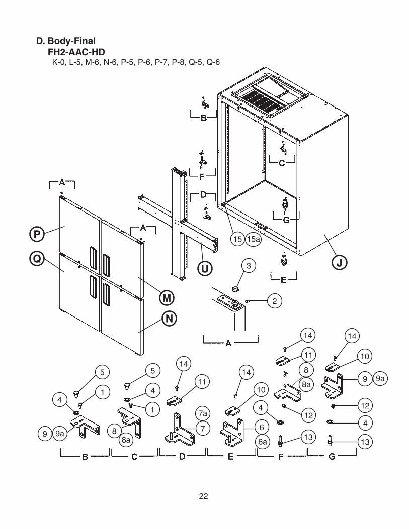
D. Body-FinalFH2-AAC-HD
K-0, L-5, M-6, N-6, P-5, P-6, P-7, P-8, Q-5, Q-6
JU
M
N
P
Q3
2
5
4
1 4
6
6a
7a
7
15
14
11
1414
11
8
8a9a9
10
10
14
12
4
1313
12
5
1
88a
4
9 9a
15a

23
Title: D. Body Final Model: FH2-AAC-HD
Index No. Description
Material or Model Number Part Number
Required Number
K-0 to
Q-6
J Body – Prefinal - 2A1347A03 1
M Door – Half (UR) - 1A0326A03 1
N Door – Half (LR) - 1A0324A03 1
P Door – Half (UL) - 1A0324A04 1
Q Door – Half (LL) - 1A0326A04 1
U Mullion – Cross - 2A1350A03 1
1 Hinge – Stop Pin PS 4A2180-01 2
2 Hinge – Tension Screw PS 4A0446-01 4
3 Hinge – Bushing Cover SS 4A0445-01 4
4 Hinge – Lock Washer PS 4A0553-01 4
5 Hinge – Pivot Pin (Top) PS 4A2179-01 2
6 Bracket – Door Hinge (LR) PS 3A1626-01 1
6a Countersunk Screw 5×10, SS 7C42-0510 3
7 Bracket – Door Hinge (LL) PS 3A1627-01 1
7a Countersunk Screw 5×10, SS 7C42-0510 3
8 Bracket – Door Hinge (UR) PS 3A1580-01 2
8a Countersunk Screw 5×10, SS 7C42-0510 6
9 Bracket – Door Hinge (UL) PS 3A1581-01 2
9a Countersunk Screw 5×10, SS 7C42-0510 6
10 Hinge – Stop Plate (R) PS 4A0441-01 2
11 Hinge – Stop Plate (L) PS 4A0441-02 2
12 Stop Pin PS 4A1734-01 2
13 Pivot Pin PS 4A1735-01 2
14 Screw – Stop Plate PS 4A0483-01 4
15 Cover – Corner ABS 3A1751-01 16
15a Truss Head Screw 5×10, SS 7C32-0510 26

24
E. Control Box AssemblyFH1-AAC(-HD), FH2-AAC(-HD)
K-0, L-0, L-5, M-5, M-6, M-7, M-8, N-5, N-6, P-5, P-6, P-7, P-8, Q-5, Q-6
76
30 2927 28
24
23
10 11
25 26
18 19
22
16 17
12 13
14 15
2120
45
8 9
2
3
31 32 33 34
1

25
Title: E. Control Box Assembly Model: FH1-AAC(-HD), FH2-AAC(-HD)
Index No. Description
Material or Model Number Part Number
Required NumberK-0 to
M-5
M-6 to
M-8 N-5 P-5P-6 P-7 Q-5 Q-6
1 Base – Control Box GS 2A1887-01 1 1 1 1 1 1 1
2 Cover – Control Box GS 2A1833-01 1 1 1 1 1 1 1
3 Board – Control Display Use latest for all aux. codes
4A2203-02 1 1 1 1 -
4A2203-05 1 -
Controller 3A3372-05 1 -
3A3656-06 1
4 Switch – Rocker 1801.110 4A0418-01 1 1 1 1 1 1 1
5 Switch – Toggle 780K21 4A0424-01 1 1 1 1 1 1 1
6 Relay – Compressor HE1aN-AC120V 4A1307-01 1 1 1 1 1 1 1
7 Tapping Screw 3×8 431415-01 1 1 1 1 1 1 1
8 Transformer BE110805GAA 4A2202-01 1 1 1 1 1 1 1
9 Tapping Screw 3×8 431415-01 2 2 2 2 2 2 2
10 Terminal Block FH1-AAC(-HD)FH2-AAC(-HD)
4A1540-01 1 -
4A2619-01 1 1 1 1 1 1
11 Tapping Screw 3×8 431415-01 1 2 2 2 2 2 2
12 Plug Housing 3/12/35 4A0425-01 1 1 1 1 1 1 1
13 Receptacle Housing 03-12-1036 4A0426-01 1 1 1 1 1 1 1
14 Plug Housing (6 Pin) 3191-06P 412832-03 1 1 1 1 1 1 1
15 Receptacle Housing (6 Pin) 3191-06R1 412831-03 1 1 1 1 1 1 1
16 Plug Housing (6 Pin) 3191-06P 412832-12 1 1 1 1 1 1 1
17 Receptacle Housing (6 Pin) 3191-06R1 412831-12 1 1 1 1 1 1 1
18 Threaded Insert M5 4A0407-01 1 1 1 1 1 1 1
19 Truss Head Screw 5×10, SS 7C32-0510 1 1 1 1 1 1 1
20 Relay – Door Switch FH1-AAC(-HD)FH2-AAC(-HD)
4A2268-01 1 -
4A2607-01 1 1 1 1 1 1
21 Tapping Screw 3×8 431415-01 2 2 2 2 2 2 2
22 Bushing SB-625-8 420470-01 2 2 2 2 2 2 2
23 Capacitor – Run FH1-AAC(-HD) 439943-04 1 -
3A2005-08 1 1 1 1 1 1FH2-AAC(-HD) 439943-02 1 -
3A2005-06 1 1 1 1 1 1
24 Capacitor – Start FH1-AAC(-HD) 3A0076-06 1 1 1 1 1 1 1FH2-AAC(-HD) 3A0076-07 1 1 1 1 1 1 1
25 Starter FH1-AAC(-HD) 4A1107-03 1 1 1 1 1 1 1
FH2-AAC(-HD) 434172-01 1 1 1 -
4A1107-13 1 1 1 1
26 Tapping Screw 3×8 431415-01 1 1 1 1 1 1 1
27 Strap FH1-AAC(-HD) 434580-08 1 1 1 1 1
434580-14 1 1
FH2-AAC(-HD) 434580-20 1 1 1 1 1 1 1
28 Tapping Screw 3×8 431415-01 1 1 1 1 1 1 1
29 Relay – Defrost - 4A2266-01 1 1 1 1 1 1 1
30 Tapping Screw 3×8 431415-01 2 2 2 2 2 2 2
31 Bracket – Fuse GS 4A3359-01 1 1 1

26
Title: E. Control Box Assembly Model: FH1-AAC(-HD), FH2-AAC(-HD)
Index No. Description
Material or Model Number Part Number
Required NumberK-0 to
M-5
M-6 to
M-8 N-5 P-5P-6 P-7 Q-5 Q-6
32 T2 Screw 4×8, SS 7P32-0408 2 2 2
33 Fuse Holder HTB92I 4A0892-01 1 1 1
34 Fuse AGC-55A250V 4A0893-09 1 1 1

27
F. Fan-Evaporator AssemblyFH1-AAC(-HD)
K-0, L-0, L-5, M-5
1
F. Fan-Evaporator AssemblyFH1-AAC(-HD)
M-6, M-7, N-5, N-6, P-5, P-6, P-7, P-8, Q-5, Q-6
43a3
2 2a
42
3 2 65
173c
3b3a
2a
2a
65

28
Title: F. Fan-Evaporator Assembly Model: FH1-AAC(-HD)
Index No. Description
Material or Model Number Part Number
Required Number
K-0to
M-5
M-6 to
P-5
P-6 to
Q-6
1 Shroud – Evaporator Fan SS 2A0846-01
Not
e: P
arts
are
not
inte
rcha
ngab
le.
For
aux
iliar
y co
des
prio
r to
M-6
, ord
er H
S-3
545
and
repl
ace
the
entir
e as
sem
bly.
For
au
xilia
ry c
odes
M-6
and
late
r, or
der
appr
opria
te p
art f
rom
this
ch
art.
-
2A2565G01 1 -
2A2565G02 1
2 Bracket – Fan Motor - 3A2480-01 2 2
2a Truss Head Screw 5×12, SS 7C32-0512 2 2
3 Motor – Fan Evap JAKEL J238-100-10070
4A1132-01-
- 4A2563-01 1 1
3a Truss Head Screw 4×40, SS 7C32-0440 4 4
3b Split Lock Washer M4, SS 7L22-0400 4 4
3c Hex Nut M4, SS 7N12-0400 4 4
4 Blade – Fan THORGREN 5562C3125L1
4A1131-01-
- 4A2802-01 1 1
5 Lock – Washer - 4A0459-01 2 2
6 Wire Tie (Twist) - 4A1223-01 2 2
7 Bushing SB-625-8 420470-01 1 1

29
Title: F. Evap-Shroud Assembly Model: FH2-AAC(-HD)
Index No. Description
Material or Model Number Part Number
Required Number
K-0 to
P-5
P-6 to
Q-6
1 Blade – Fan (Pusher) AIR DRIVE INC.AD9CCW30UBA
3A0438-01 1 1
1a Lock Washer 4A0459-01 1 1
2 Motor – Evap Fan MORRILL PSC4BE9BEA1
4A0413-01 1 1
3 Orifice – Evap Fan SS 4A0412-01 1 1
3a T2 Screw 4×8, SS 7P32-0408 3 3
4 Shroud – Evap Fan SS 1A0100-01 1 -
1A0100-02 1
4a Hex Nut 4A1345-01 1 1
5 Bracket – Heater Supply - 3A3243-01 1
6 Heater – Glass Tube - 3A2335-02 1
6a T2 Screw 4x8 7P32-0408 2
7 Wire Tie (Twist) - 4A1223-01 4
8 Bushing - 428394-02 2
9 Nylon Tie CV-100 8911-0100 4
F. Evap-Shroud AssemblyFH2-AAC(-HD)
K-0, L-5, M-5, M-6, M-7, M-8, N-5, N-6, P-5, P-6, P-7, P-8, Q-5, Q-6
98
8
4
2 13 3a
4a
1a
5
6 6a
7
7

30
G. Evaporator AssemblyFH1-AAC(-HD)
K-0, L-0, L-5, M-5, M-6, M-7, N-5, N-6, P-5, P-6, P-7, P-8, Q-5, Q-6
2a2
1
8
7
9
3
6
4
10
5 5a

31
Title: G. Evaporator Assembly Model: FH1-AAC(-HD)
Index No. Description
Material or Model Number Part Number
Required Number
K-0
L-0 to
P-5
P-6 to
Q-6
1 Evaporator - 2A0781-01 1 1 1
2 Bracket – Evaporator SS 4A2542-01 2 2 2
2a T2 Screw 4×8, SS 7P32-0408 4 4 4
3 Thermistor – Defrost Thermistor is to be replaced using kit HS-3540. Apply to all aux. codes.
- - -
Clip – Thermistor 4A3248G01 1 1 1
4 Heater – Defrost - 3A0846-01 1 1 1
5 Thermistat – Defrost - 4A0954-02 1 1 1
5a T2 Screw 4x8, SS 7P32-0408 2 2 2
6 Bushing 0CB-500 428394-02 1 1 1
7 Expansion Valve - 4A1135-01 1 1 1
8 Expansion Valve Cover (A) - 3A0372-01 1 1 1
9 Expansion Valve Cover (B) - 3A0372-02 1 1 1
10 Nylon Tie 8911-0150 1

32
11
10
1312
G. Evaporator AssemblyFH2-AAC(-HD)
K-0, L-5, M-5, M-6, M-7, M-8, N-5, N-6, P-5, P-6, P-7, P-8, Q-5, Q-6
1
4
3 3a
5 5a
6
2 2a
9
8
147
These additional parts added to FH2-AAC(-HD) Evaporator Assembly at aux. code M-6

33
Installation Instructions for Parts 10, 11, 12, & 13
1. The original heat shield must be removed. This can be done by lifting the evaporator up and sliding the heat shield out.
2. The new heat shield (part #13) is then installed in the rotocast drain pan.
3. The clips are then slid onto the end plate on the evaporator. Support clips (part #12) are installed onto the hairpin end of the evaporator as shown in the illustration.
4. The other support clips (parts #10 and #11) are installed on the return bend end (same side as inlet andoutlet tubes) as shown in the illustration.
NOTE: All clips are shown in the illustration in the correct orientation for installation. The parts are slid onto the evaporator bracket using the tab on the support clip.
Title: G. Evaporator Assembly Model: FH2-AAC(-HD)
Index No. Description
Material or Model Number Part Number
Required Number
K-0 to
M-5
M-6to
P-5 P-6
P-7to
Q-6
1 Evaporator - 2A0636-01 1 1 1 1
2 Bracket-Evap Shroud (R) SS 4A0545-01 1 1 -
2a T2 Screw 4×8, SS 7P32-0408 2 2 -
3 Bracket-Evap Shroud (L) SS 4A0548-01 1 1 -
3a T2 Screw 4×8, SS 7P32-0408 2 2 -
4 Heater – Defrost - 3A0591-01 1 1 1 1
5 Thermostat – Defrost - 4A0954-02 1 1 1 1
5a T2 Screw 4×8, SS 7P32-0408 2 2 2 2
6 Bushing - 420470-01 1 1 1 1
7 Thermistor – Defrost Thermistor is to be replaced using kit HS-3540. Apply to all aux. codes.
- - - -
Thermistor – Clip 320418-01 1 1 1 1
8 “Y” Joint - 4A1687-03 1 1 1 1
9 “Y” Joint - 4A1687-02 1 1 1 1
10 Clip – Support Evap (A) - 4A2826-01 1 1 1
11 Clip – Support Evap (B) - 4A2827-01 1 1 1
12 Clip – Support Evap (C) - 4A2828-01 2 2 2
13 Shield – Heat - 3A1853G01 1 1 1
14 Nylon Tie - 8911-0150 1

34
H. Condenser AssemblyFH1-AAC(-HD)
K-0, L-0, L-5, M-5, M-6, M-7, N-5, N-6, P-5, P-6, P-7, P-8, Q-5, Q-6
10 10a
3a3
1a1 8a8
9
7a7
65
4
2
35
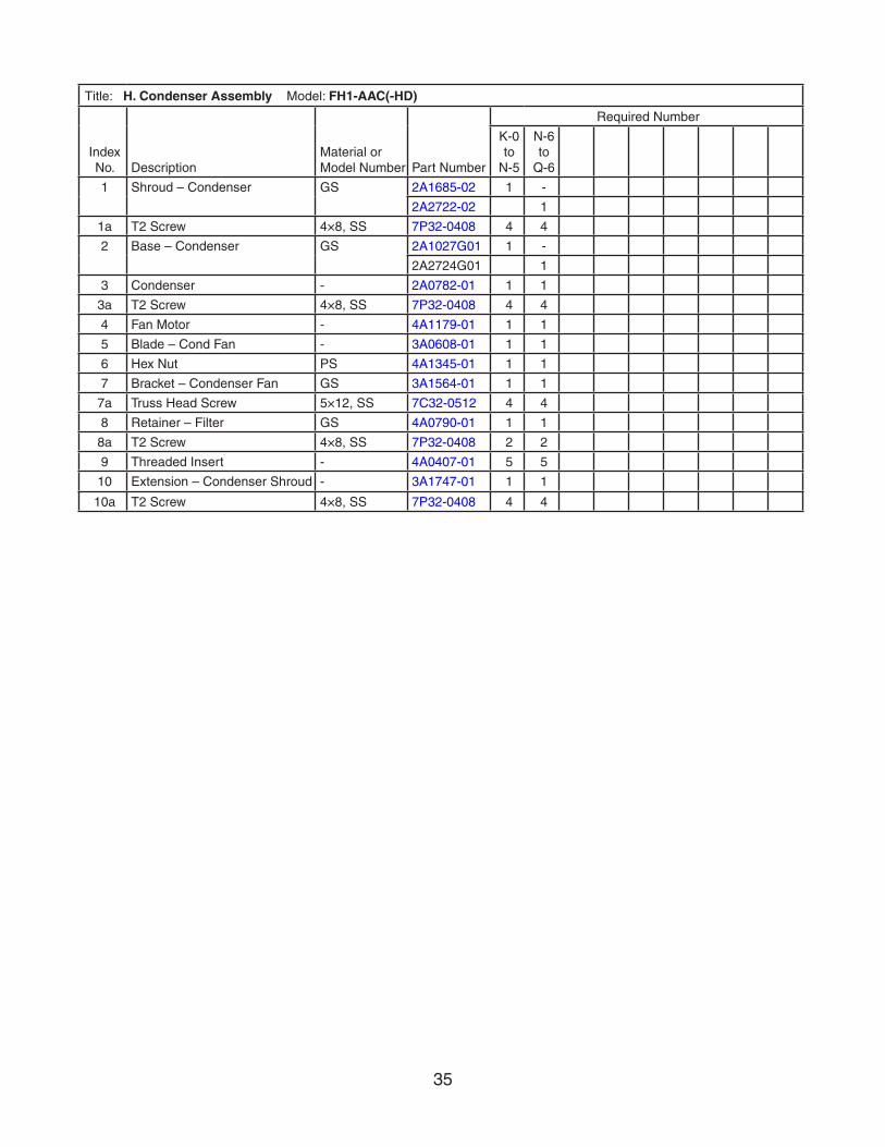
Title: H. Condenser Assembly Model: FH1-AAC(-HD)
Index No. Description
Material or Model Number Part Number
Required Number
K-0 to
N-5
N-6 to
Q-6
1 Shroud – Condenser GS 2A1685-02 1 -
2A2722-02 1
1a T2 Screw 4×8, SS 7P32-0408 4 4
2 Base – Condenser GS 2A1027G01 1 -
2A2724G01 1
3 Condenser - 2A0782-01 1 1
3a T2 Screw 4×8, SS 7P32-0408 4 4
4 Fan Motor - 4A1179-01 1 1
5 Blade – Cond Fan - 3A0608-01 1 1
6 Hex Nut PS 4A1345-01 1 1
7 Bracket – Condenser Fan GS 3A1564-01 1 1
7a Truss Head Screw 5×12, SS 7C32-0512 4 4
8 Retainer – Filter GS 4A0790-01 1 1
8a T2 Screw 4×8, SS 7P32-0408 2 2
9 Threaded Insert - 4A0407-01 5 5
10 Extension – Condenser Shroud - 3A1747-01 1 1
10a T2 Screw 4×8, SS 7P32-0408 4 4

36
H. Condenser AssemblyFH2-AAC(-HD)
K-0, L-5, M-5, M-6, M-7, M-8, N-5, N-6, P-5, P-6, P-7, P-8, Q-5, Q-6
3
4 5
98
2 2a
1
10 10a6a6 7
9a
Title: H. Condenser Assembly Model: FH2-AAC(-HD)
Index No. Description
Material or Model Number Part Number
Required Number
K-0 to
P-5
P-6 to
Q-6
1 Condenser - 2A0638-01 1 1
2 Shroud – Condenser GS 2A1491-01 1 1
2a T2 Screw 4×8, SS 7P32-0408 8 -
4×12, SS 7P32-0412 8
3 Fan Motor - 440911-01 1 -
4A3158-01 1
4 Fan Blade (Puller) - 4a1865-01 1 1
5 Self – Locking Nut 8 × 32 7N21I0832 4 4
6 Bracket – Cond Fan Mtr GS 2A1668-01 1 1
6a Truss Head Screw 5×12 7C32-0512 4 4
7 Base – Condenser GS 2A1217-01 1 1
8 Threaded Insert - 4A0407-01 5 5
9 Retainer – Filter - 4A2138-01 1 1
9a T2 Screw 4×8, SS 7P32-0408 2 2
10 Capacitor - 443192-02 1 1
10a T2 Screw 4X8, SS 7P32-0408 1 1

37
R
J. Body-PrefinalFH1-AAC(-HD)
K-0, L-0, L-5, M-5, M-6, M-7, N-5, N-6, P-5, P-6, P-7, P-8, Q-5, Q-6
M-6 and earlier
The santoprene light socket was changed to a porcelain lampholder at M-7. This change is non-interchangeable. If the light socket is not operating on a unit with a santoprene light socket, Hoshizaki recommends replacement with HS-3554.
Note:
Parts 3, 4, 4a, 4b and 4c are not included in HS-3554; they are shown for reference only.
HS1
3
4a4
HS2
HS1a
HS2a
68a8
77
1
2a2
5
R1
9
(Heater-Drain adhered to interior top panel with aluminum tape)
M-7 and later
11
3
4a4
10

38
Title: J. Body-Prefinal Model: FH1-AAC(-HD)
Index No. Description
Material or Model Number Part Number
Required Number
K-0to
M-6
M-7 to
P-5
P-6 to
Q-6
R Distributor – Air Top Assm 2A0438G01 1 1 -
2A3086A01 1
R1 T2 Screw 4×8, SS 7P32-0408 7 7 7
1 Cabinet Prefoam FH1-AAC 1A0173G04 1 1 1
FH1-AAC-HD 1A0353G03 1 1 1
2 Pilaster AL 3A0145-21 4 4 4
2a Truss Head Screw 5×10, SS 7C32-0510 12 12 12
3 Bulb – Light - 4A0437-01 1 -
- 4A2420-01 1 1
4 Shield – Light STANDARD KEIL, 2778-1010-3000
4A0465-01 1 1 1
4a Cheese Head Screw 5×12, SS 7C52-0512 2 2 2
4b Washer 8, SS 7W22-0800 2 -
5 Switch – Door NYLON 3A1826-01 1 1 1
6 Vinyl Hose L=1700 7730I3812 1 1 1
7 Bushing OCB-875 428394-04 2 2 2
8 Divider – Air AL 2A0199-21 1 1 1
8a T2 Screw 4×8, SS 7P32-0408 4 4 4
9 Heater – Drain 10758 25W115V 4A2975-03 1
10 Threaded Insert (Wide) 4A0839-01 Non-interchangeable part change. If light socket is not operating for these codes, Hoshizaki recommends replacement with HS-3554 (below).
2 2
11 Lampholder - 4A2862-01 1 1
HS-3554-Lampholder Conversion Kit
Index No. Description
Material or Model Number Part Number
Required Number
M-6 and earlier
HS1 Plate – Lampholder Mount SS 4A2880-01 1
HS1a Cheese Head Screw SS 7C52-0512 2
HS2 Lampholder 4A2862-01 1
HS2a Terminal – Flag DNFR18-250FIBK
8101-18FJ 2

39
J. Body-PrefinalFH2-AAC(-HD)
K-0, L-5, M-5, M-6, M-7, M-8, N-5, N-6, P-5, P-6, P-7, P-8, Q-5, Q-6
4
1
8
6 6a2a2 2b
8
7 7a5 5a
3
3
2b

40
Title: J. Body-Prefinal Model: FH2-AAC(-HD)
Index No. Description
Material or Model Number Part Number
Required Number
K-0 to
P-6
P-7 to
Q-6
1 Cabinet – Prefoam - 2A0706G05 1 1
2 Pilaster AL 3A0145-21 4 4
2a Truss Head Screw 5×10, SS 7C32-0510 12 12
2b Threaded Insert M5 4A0407-01 18 18
3 Switch – Door NYLON 3A1826-01 2 2
4 Vinyl Hose L=1700 7730I3812 1 1
5 Baffle – Air - 2A0625-01 1 1
5a Truss Head Screw 5×10, SS 7C32-0510 2 2
6 Pilaster – Mullion AL 2A0205-21 2 -
2A3246-21 2
6a Truss Head Screw 5×10, SS 7C32-0510 6 6
7 Divider – Air AL 2A0199-21 1 1
7a T2 Screw 4×8, SS 7P32-0408 4 4
8 Bushing OCB-875 428394-04 4 4
41
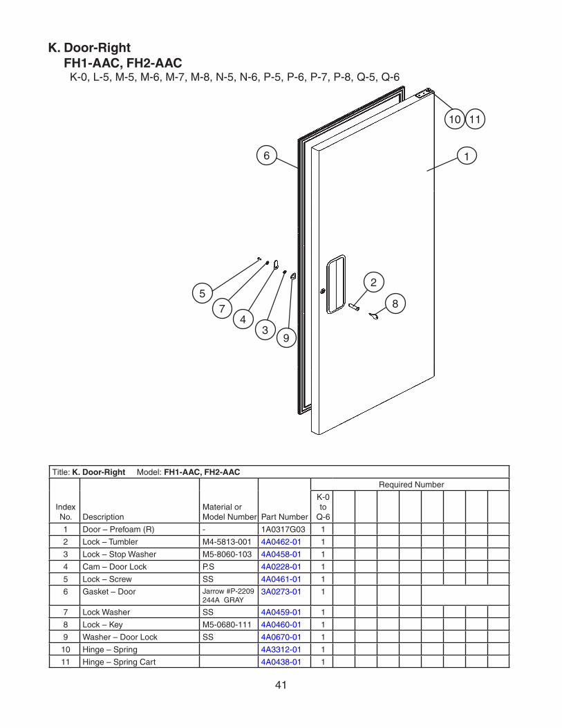
K. Door-RightFH1-AAC, FH2-AAC
K-0, L-5, M-5, M-6, M-7, M-8, N-5, N-6, P-5, P-6, P-7, P-8, Q-5, Q-6
Title: K. Door-Right Model: FH1-AAC, FH2-AAC
Index No. Description
Material or Model Number Part Number
Required Number
K-0 to
Q-6
1 Door – Prefoam (R) - 1A0317G03 1
2 Lock – Tumbler M4-5813-001 4A0462-01 1
3 Lock – Stop Washer M5-8060-103 4A0458-01 1
4 Cam – Door Lock P.S 4A0228-01 1
5 Lock – Screw SS 4A0461-01 1
6 Gasket – Door Jarrow #P-2209244A GRAY
3A0273-01 1
7 Lock Washer SS 4A0459-01 1
8 Lock – Key M5-0680-111 4A0460-01 1
9 Washer – Door Lock SS 4A0670-01 1
10 Hinge – Spring 4A3312-01 1
11 Hinge – Spring Cart 4A0438-01 1
34
75
6
10 11
2
1
8
9

42
L. Door-LeftFH2-AAC
L-5, M-5, M-6, M-7, M-8, N-5, N-6, P-5, P-6, P-7, Q-5, Q-6
Title: L. Door-Left Model: FH2-AAC
Index No. Description
Material or Model Number Part Number
Required Number
L-5 to
Q-6
1 Door – Prefoam (L) - 1A0317G04 1
2 Lock – Tumbler M4-5813-001 4A0462-01 1
3 Lock – Stop Washer M5-8060-103 4A0458-01 1
4 Cam – Door Lock P.S 4A0228-01 1
5 Lock – Screw SS 4A0461-01 1
6 Gasket – Door JARROW #P-2209244A GRAY
3A0273-01 1
7 Lock Washer SS 4A0459-01 1
8 Lock – Key M5-0680-111 4A0460-01 1
9 Washer – Door Lock SS 4A0670-01 1
10 Hinge – Spring 4A3312-02 1
11 Hinge – Spring Cart 4A0438-02 1
10 11
1
47
5
28
39
6

43
M. Door-Half (UR)FH1-AAC-HD, FH2-AAC-HD
K-0, L-0, L-5, M-5, M-6, M-7, N-6, P-5, P-6, P-7, P-8, Q-5, Q-6
Title: M. Door-Half (UR) Model: FH1-AAC-HD, FH2-AAC-HD
Index No. Description
Material or Model Number Part Number
Required Number
K-0 to
Q-6
1 Door – Prefoam (UR) - 1A0325G03 1
2 Lock – Tumbler M4-5813-001 4A0462-01 1
3 Lock – Stop Washer M5-8060-103 4A0458-01 1
4 Cam – Door Lock P.S 4A0228-01 1
5 Lock – Screw SS 4A0461-01 1
6 Gasket – Door (Half) JARROW#P-2209244A GRAY
3A0273-02 1
7 Lock Washer SS 4A0459-01 1
8 Lock – Key M5-0680-111 4A0460-01 1
9 Washer – Door Lock SS 4A0670-01 1
10 Hinge – Spring 4A3312-01 1
11 Hinge – Spring Cart 4A0438-01 1
1110
9
1
6
7
5
3
8
2
4

44
N. Door-Half (LR)FH1-AAC-HD, FH2-AAC-HD
K-0, L-0, L-5, M-5, M-6, M-7, N-6, P-5, P-6, P-7, P-8, Q-5, Q-6
Title: N. Door Half (LR) Model: FH1-AAC-HD, FH2-AAC-HD
Index No. Description
Material or Model Number
Part Number
Required Number
K-0 to
Q-6
1 Door – Prefoam (LR) - 1A0323G03 1
2 Lock – Tumbler M4-5813-001 4A0462-01 1
3 Lock – Stop Washer M5-8060-103 4A0458-01 1
4 Cam – Door Lock P.S 4A0228-01 1
5 Lock – Screw SS 4A0461-01 1
6 Gasket – Door (Half) JARROW P-2209 244A GRAY
3A0273-02 1
7 Lock Washer SS 4A0459-01 1
8 Lock – Key M5-0680-111 4A0460-01 1
9 Washer – Door Lock SS 4A0670-01 1
10 Hinge – Spring 4A3312-01 1
11 Hinge – Spring Cart 4A0438-01 1
82
46
75
3
1
9
1110

45
P. Door-Half (UL)FH2-AAC-HD
K-0, L-5, M-6, N-6, P-5, P-6, P-7, P-8, Q-5, Q-6
Title: P. Door-Half (UL) Model: FH2-AAC-HD
Index No. Description
Material or Model Number
Part Number
Required Number
K-0 to
Q-6
1 Door – Prefoam (UL) - 1A0323G04 1
2 Lock – Tumbler M4-5813-001 4A0462-01 1
3 Lock – Stop Washer M5-8060-103 4A0458-01 1
4 Cam – Door Lock P.S 4A0228-01 1
5 Lock – Screw SS 4A0461-01 1
6 Gasket – Door (Half) Jarrow #P-2209244A GRAY
3A0273-02 1
7 Lock Washer SS 4A0459-01 1
8 Lock – Key M5-0680-111 4A0460-01 1
9 Washer – Door Lock SS 4A0670-01 1
10 Hinge – Spring 4A3312-02 1
11 Hinge – Spring Cart 4A0438-02 1
10 11
1
5
7
34
9
6
2
8

46
Q. Door-Half (LL)FH2-AAC-HD
K-0, L-5, M-6, N-6, P-5, P-6, P-7, P-8, Q-5, Q-6
Title: Q. Door-Half (LL) Model: FH2-AAC-HD
Index No. Description
Material or Model Number Part Number
Required Number
K-0 to
Q-6
1 Door – Prefoam (LL) - 1A0325G04 1
2 Lock – Tumbler M4-5813-001 4A0462-01 1
3 Lock – Stop Washer M5-8060-103 4A0458-01 1
4 Cam – Door Lock P.S 4A0228-01 1
5 Lock – Screw SS 4A0461-01 1
6 Gasket – Door (Half) Jarrow #P-2209244A GRAY
3A0273-02 1
7 Lock Washer SS 4A0459-01 1
8 Lock – Key M5-0680-111 4A0460-01 1
9 Washer – Door Lock SS 4A0670-01 1
10 Hinge – Spring 4A3312-02 1
11 Hinge – Spring Cart 4A0438-02 1
1110
1
2
3
45
76
9
8

47
R. Distributor-Air Top AssemblyFH1-AAC-(HD)
K-0, L-5, M-6, N-6, P-5, P-6, P-7, P-8, Q-5, Q-6
Title: R. Distributor-Air Top Assembly Model: FH1-ACC(-HD)
Index No. Description
Material or Model Number Part Number
Required Number
K-0 to
P-5P-6P-7
P-8 Q-6
1 Distributor – Air (Top) ABS 2A0610-01 1
2A0610-03 1 -
2A0610-04 1
2 Shield – Duct 2A3085-01 1 -
2A3392-01 1
3 Bracket – Heater Supply 3A3096G01 1 1
3a Truss Head Screw 5x12 7C32-0512 4 6
4 Heater – Glass Tube 3A2335-02 2 2
1
2
3a3
4
48
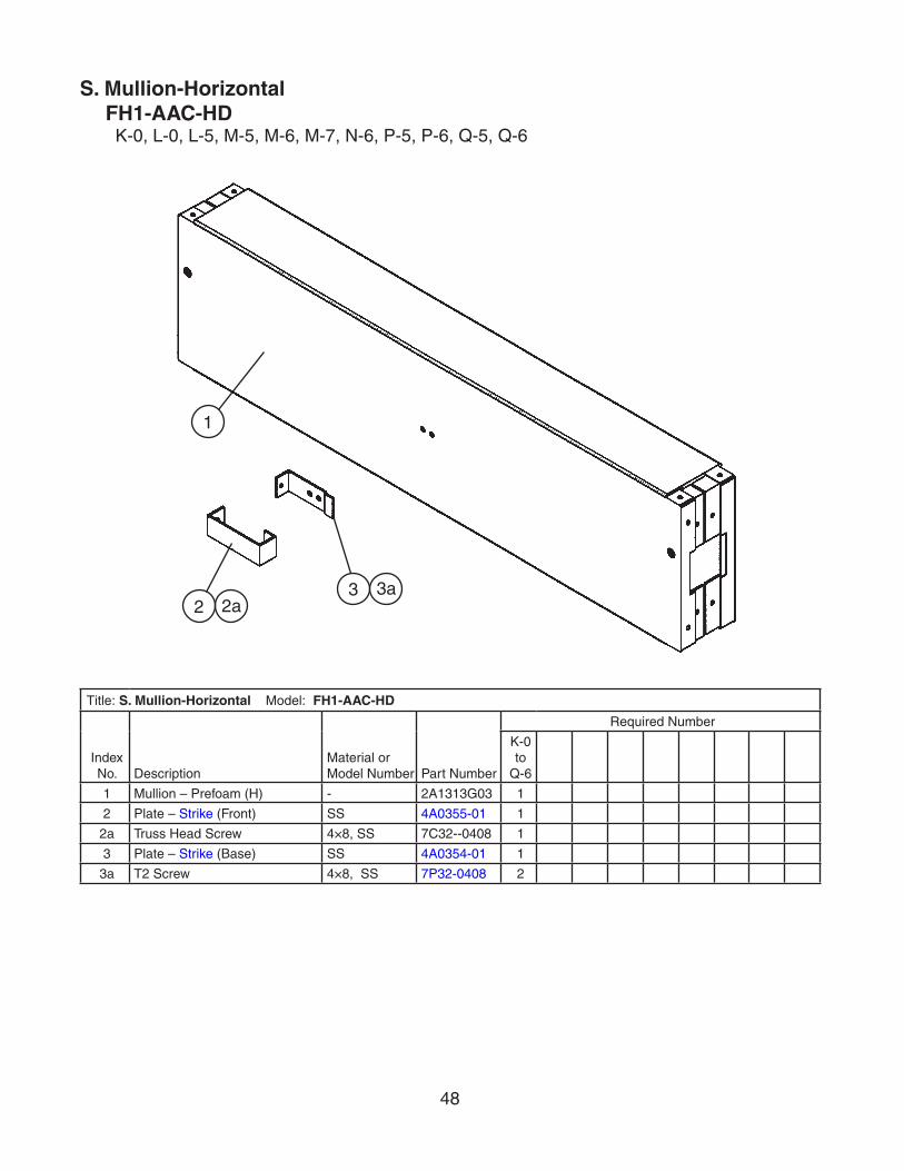
S. Mullion-HorizontalFH1-AAC-HD
K-0, L-0, L-5, M-5, M-6, M-7, N-6, P-5, P-6, Q-5, Q-6
Title: S. Mullion-Horizontal Model: FH1-AAC-HD
Index No. Description
Material or Model Number Part Number
Required Number
K-0 to
Q-6
1 Mullion – Prefoam (H) - 2A1313G03 1
2 Plate – Strike (Front) SS 4A0355-01 1
2a Truss Head Screw 4×8, SS 7C32--0408 1
3 Plate – Strike (Base) SS 4A0354-01 1
3a T2 Screw 4×8, SS 7P32-0408 2
2a
1
23a3

49
T. Mullion-VerticalFH2-AAC
L-5, M-5, M-6, M-7, M-8, N-5, N-6, P-5, P-6, P-7, Q-5, Q-6
M-8 and later
8
5
6 6a
M-7 and earlier
The santoprene light socket was changed to a porcelain lampholder at M-8. This change is non-interchangeable. If the light socket is not operating on a unit with a santoprene light socket, Hoshizaki recommends replacement with HS-3554.
Note: Parts 5, 6, and 6a are not included in HS-3554; they are shown for reference only.
HS1
5
6a6
HS2
HS1a
HS2a
1
2
4a
3a3
4
2a 2b
7

50
Title: T. Mullion-Vertical Model: FH2-AAC
Index No. Description
Material or Model Number Part Number
Required Number
L-5 to
M-7
M-8 to
P-6
P-7 to
Q-6
1 Mullion – Prefoam - 2A1288G04 1 1 1
2 Pilaster – Mullion AL 2A0205-21 2 2 -
2A3246-21 2
2a Truss Head Screw 5×10, SS 7C32-0510 6 6 6
2b Threaded Insert 4A0407-01 6 6 6
3 Plate – Strike (Front) SS 4A0355-01 1 1 1
3a Truss Head Screw 4×8, SS 7C32-0408 1 1 1
4 Plate – Strike (Base) SS 4A0354-01 1 1 1
4a T2 Screw 4×8, SS 7P32-0408 2 2 2
5 Bulb – Light GE, 40A15 4A0437-01 1 -
- 4A2420-01 1 1
6 Shield – Light 2778-1010-3000 4A0465-01 1 1 1
6a Cheese Head Screw 5×12, SS 7C52-0512 2 2 2
6b Washer 8, SS 7W22-0800 2 -
7 Threaded Insert – Wide - 4A0839-01 Non-interchangeable part change. If light socket is not operating for these codes, Hoshizaki recommends replacement with HS-3554 (below).
1 1
8 Lampholder - 4A2862-01 1 1
HS-3554-Lampholder Conversion Kit
Index No. Description
Material or Model Number Part Number
Required Number
M-7 and earlier
HS1 Plate – Lampholder Mount SS 4A2880-01 1
HS1a Cheese Head Screw SS 7C52-0512 2
HS2 Lampholder 4A2862-01 1
HS2a Terminal – Flag DNFR18-250FIBK
8101-18FJ 2

51
U. Mullion-CrossFH2-AAC-HD
K-0, L-5, M-6, N-6, P-5, P-6, P-7, P-8, Q-5, Q-6
M-6 and earlier
The santoprene light socket was changed to a porcelain lampholder at N-6. This change is non-interchangeable. If the light socket is not operating on a unit with a santoprene light socket, Hoshizaki recommends replacement with HS-3554.
Note:
Parts 5, 6, and 6a are not included in
HS-3554; they are shown for reference only.
HS1
5
HS2
HS1a
HS2a
6a6
N-6 and later
8
5
1
34
2 2a
4a3a 6 6a
2b 7

52
Title: U. Mullion-Cross Model: FH2-AAC-HD
Index No. Description
Material or Model Number Part Number
Required Number
K-0 to
M-6
N-6 to
P-7
P-8 to
Q-6
1 Mullion – Prefoam - 2A1288G03 1 1 1
2 Pilaster – Mullion AL 2A0205-21 2 2 -
2A3246-21 2
2a Truss Head Screw 5×10, SS 7C32-0510 6 6 6
2b Threaded Insert 4A0407-01 6 6 6
3 Plate – Strike (Front) SS 4A0355-01 1 1 1
3a Truss Head Screw 4×8, SS 7C32-0408 1 1 1
4 Plate – Strike (Base) SS 4A0354-01 1 1 1
4a T2 Screw 4×8, SS 7P32-0408 4 4 4
5 Bulb – Light GE, 40A15 4A0437-01 1 -
- 4A2420-01 1 1
6 Shield – Light 2778-1010-3000 4A0465-01 1 1 1
6a Cheese Head Screw 5×12, SS 7C52-0512 2 2 2
6b Washer 8, SS 7W22-0800 2 -
7 Threaded Insert Wide - 4A0839-01 Non-interchangeable part change. If light socket is not operating for these codes, Hoshizaki recommends replacement with HS-3554 (below).
6 6
8 Lampholder - 4A2862-01 1 1
HS-3554-Lampholder Conversion Kit
Index No. Description
Material or Model Number Part Number
Required Number
M-6 and earlier
HS1 Plate – Lampholder Mount SS 4A2880-01 1
HS1a Cheese Head Screw SS 7C52-0512 2
HS2 Lampholder 4A2862-01 1
HS2a Terminal – Flag DNFR18-250FIBK
8101-18FJ 2

53
Title: V. Label Location Model: FH1-AAC(-HD)
Index No. Description
Material or Model Number Part Number
Required Number
K-0 L-5
M-5to
P-5
P-6to
P-8
Q-5to
Q-6
1 Label – Penguin – HA(L) - 4A0526-02 1 1 1 1
2 Emblem – Hoshizaki - 4A0560-01 1 1 1 1
3 Label – Door Heater Switch PVC Film 4A1039-01 1 1 1 1
4 Caution Label PVC Film 4A1931-01 1 1 1 1
5 Wiring Label PVC Film 2A1934-01 1 1 -
2A2340-01 1 1
6 Label – R404A - 4A0960-01 1 1 1 1
7 Label – Power - 4A2196-01 1 1 1 1
8 Label – Display - 4A2286-01 1 1 1 1
9 Cover – Nameplate - 4A2265-01 1
V. Label LocationFH1-AAC(-HD)
K-0, L-0, L-5, M-5, M-6, M-7, N-5, N-6, P-5, P-6, P-7, P-8, Q-5, Q-6
1
8
2
6
5
4
73
9

54
Title: V. Label Location Model: FH2-AAC(-HD)
Index No. Description
Material or Model Number Part Number
Required Number
K-0
L-5 to
P-5
P-6 to
P-8 Q-5Q-6
1 Label – Penguin – HA(L) - 4A0526-02 1 1 1 1
2 Emblem – Hoshizaki - 4A0560-01 1 1 1 1
3 Label – Door Heater Switch PVC Film 4A1039-01 1 1 1 1
4 Caution Label PVC Film 4A1931-01 1 1 1 1
5 Wiring Label PVC Film 2A1952-01 1 1 -
2A2342-01 1 1
6 Label – R-404A - 4A0960-01 1 1 1 1
7 Label – Power - 4A2196-01 1 1 1 1
8 Label – Display - 4A2286-01 1 1 1 1
9 Label – Warning 4A2968-01 1 1 1 1
10 Cover Nameplate 4A3727-01 1
V. Label LocationFH2-AAC(-HD)
K-0, L-5, M-5, M-6, M-7, M-8, N-5, N-6, P-5, P-6, P-7, P-8, Q-5, Q-6
2 8
16 5
3
7
104
9

55
Title: W. Literature & Packaging Model: FH1-AAC(-HD), FH2-AAC(-HD)
Index No. Description
Material or Model Number Part Number
Required Number
K-0 to
P-7
P-8 to
Q-6
1 Instruction Manual Paper 91A34010L 1 1
Packaging (Available only for models currently in production)
FH1-AAC 1A0765A17 1 1FH1-AAC-HD 1A0765A18 1 1FH2-AAC 1A0766A13 1 1FH2-AAC-HD 1A0766A14 1 1
1 Filler – Door 4A2977-01 2 2
2 Pad – Corner 3A2598-01 4 4
3 Post – Corner 3A2603-01 4 4
4 Support – Corner 3A2596-01 4 4
5 Stop – Door 4A1873-01 1 1
6 Stop – Door (Center) FH1-AAC-HD FH2-AAC-HD
4A1874-01 1 1
7 Flat Washer 7W21I5800 4 4
8 Hex Head Bolt 7B01 I5825 4 4
9 Pallet FH1-AAC(-HD) 3A1814-01 1 1FH2-AAC(-HD) 3A1815-01 1 1
10 Protector – Front FH2-AAC(-HD) 3A2595-01 1 1
11 Caster Shim HS-3590 1
12 Caster Kit HS-3546 1
13 Shelf Pack HS-3508 1
W. Literature & PackagingFH1-AAC(-HD), FH2-AAC(-HD)
K-0, L-0, L-5, M-5, M-6, M-7, M-8, N-5, N-6, P-5, P-6, P-7, P-8, Q-5, Q-6