Embed Size (px)
Citation preview
6 November 2013
Ref: 028900REP01 Rev2
ABM Resources NL Level 1/141 Broadway Nedlands WA 6009 Attention: Mr Justin Robins Environmental Manager Dear Justin RE: TWIN BONANZA PROJECT, TANAMI DESERT,NORTHERN TERRITORY
TAILINGS STORAGE FACILITY REVISED GEOTECHNICAL CONCEPTUAL DESIGN REPORT
4DGeotechnics Pty Ltd is pleased to submit to ABM Resources NL our revised Geotechnical Conceptual Design Report for their proposed tailing storage facility at the Twin Bonanza Project.
We emphasise that this report is based on desk-top level information only, and is intended to provide conceptual information to allow planning and permitting applications to proceed. It is important to recognise that appropriate ground investigations will be required to prove up the concepts presented here and to develop final tailings storage design plans and a supporting report.
We trust that this report meets with your current requirements. If you have any questions or require any further information or clarification, please contact Brian Francis or the undersigned. We would be pleased to be given the opportunity to assist ABM Resources NL with any further works on the tailings storage development, or in fact with any access roads, infrastructure items or pit slope stability for the Twin Bonanza Project that you may require.
4DGeotechnics Pty Ltd
Ian H Lewis PRINCIPAL ENGINEERING GEOLOGIST Distribution:
Original held by 4DG
1 Hard copy ABM Resources NL
1 Electronic copy ABM Resources
ABM RESOURCES NL
TWIN BONANZA PROJECT TANAMI DESERT, NORTHERN TERRITORY
TAILINGS STORAGE FACILITY REVISED GEOTECHNICAL CONCEPTUAL DESIGN REPORT
Ref: 028900REP01 Rev2
06 NOVEMBER 2013
2 Clients Comments
Incorporated RJR BRF IHL IHL 06/11/2013
1 Clients Comments
Incorporated RJR BRF IHL IHL 18/10/2013
0 Issued for Use RJR BRF IHL IHL 12/09/2013
A Internal Review RJR BRF IHL 11/09/2013
Revision Amendment Prepared by Checked by Authorised Date
J:\Jobs\028900_ABM Resources Twin Bonanaza Gold Mine TSF\08_Reports\02_Factual Reports\028900REP01 Rev2.docx
Ref: 028900REP01 Rev2
Commercial in Confidence
6 November 2013 Page i
CONTENTS Page
1.0 INTRODUCTION ................................................................................................................. 1
2.0 BACKGROUND ................................................................................................................... 1
2.1 PROJECT OVERVIEW ................................................................................................................. 1
2.2 EXISTING INFORMATION .......................................................................................................... 1
2.3 PREVIOUS INVESTIGATION AND WORKS .................................................................................. 2
3.0 PROJECT APPRECIATION ..................................................................................................... 2
3.1 OBJECTIVES .............................................................................................................................. 3
4.0 GENERAL SITE DESCRIPTION ............................................................................................... 4
4.1 ENVIRONMENTAL SETTING ...................................................................................................... 4
4.1.1 Climate ............................................................................................................................. 4
4.1.2 Flora and Fauna ............................................................................................................... 4
4.2 TOPOGRAPHIC SETTING ........................................................................................................... 4
4.3 GEOLOGICAL SETTING .............................................................................................................. 4
4.3.1 Local Geology ................................................................................................................... 4
4.4 SURFACE WATER AND GROUNDWATER ................................................................................... 5
4.4.1 Surface Water................................................................................................................... 5
4.4.2 Groundwater .................................................................................................................... 5
5.0 DETAILED SITE CHARACTERISATION .................................................................................... 6
5.1 GENERAL .................................................................................................................................. 6
5.2 SUBSURFACE CONDITIONS ....................................................................................................... 6
6.0 CONCEPTUAL TAILINGS STORAGE FACILITY CONCEPTS ........................................................ 7
6.1 DESIGN STANDARDS ................................................................................................................. 7
6.2 DESIGN ELEMENTS ................................................................................................................... 7
6.3 DESIGN APPROACH .................................................................................................................. 8
6.3.1 Storage Characteristics .................................................................................................... 9
6.3.2 Embankment Design ........................................................................................................ 9
6.3.3 Liner Options .................................................................................................................. 10
6.3.4 Tailings Management .................................................................................................... 10
6.3.5 Monitoring ..................................................................................................................... 11
6.4 CONSTRUCTION SEQUENCING ............................................................................................... 12
6.5 GEOTECHNICAL ASSESSMENT ................................................................................................ 13
6.5.1 General ........................................................................................................................... 13
6.5.2 Geological Model for Analyses ....................................................................................... 13
6.5.3 Tailings ........................................................................................................................... 14
6.5.4 Overburden..................................................................................................................... 14
Ref: 028900REP01 Rev2
Commercial in Confidence
6 November 2013 Page ii
6.5.5 Bedrock ........................................................................................................................... 14
6.5.6 Model Geometry ............................................................................................................ 14
6.6 SEEPAGE ANALYSIS ...................................................................................................................... 14
6.6.1 Tailings Storage Facility.................................................................................................. 15
6.6.2 Concentrate Residual Dam ............................................................................................. 15
6.7 STABILITY ANALYSIS..................................................................................................................... 16
6.7.1 Freeboard Calculations ................................................................................................... 18
6.8 END OF OPERATIONAL LIFE CLOSURE ..................................................................................... 18
6.9 CONSTRUCTION CONSIDERATIONS AND DESIGN IMPLICATIONS .......................................... 19
7.0 RECOMMENDATIONS ....................................................................................................... 20
8.0 LIMITATIONS ................................................................................................................... 20
9.0 REFERENCES .................................................................................................................... 22
10.0 GLOSSARY ....................................................................................................................... 23
LIST OF TABLES
Table 1A Summary of Anticipated Earthworks Volumes - Option 1
Table 1B Summary of Anticipated Earthworks Volumes - Option 2
Table 2 Summary of Recommended Soil and Synthetic Liner Systems
Table 3 Monitoring Frequency of TSF Components over the Life-of-Mine
Table 4 Summary of Material Properties for Seepage Analyses
Table 5 Summary of Material Properties for Stability Analyses
Table 6 Summary of Stability Analysis Results
LIST OF FIGURES
Figure 1 Site Location Plan
Figure 2 Approximate Exploratory Test Locations
Figure 3 Option 1 - Plan of Modifications
Figure 4 Option 2 - Plan of Modifications
Figure 5 Assumed Depth to Bedrock
Figure 6 Concentrate Residual Dam Layout
Figure 7 Option 1 - TSF 1 Layout
Figure 8 Option 1 - TSF 2 Layout
Figure 9 Option 2 - TSF 1A Layout
Figure 10 Option 2 - TSF 1B Layout
Figure 11 Option 2 - TSF 2A Layout
Figure 12 Option 2 - TSF 2B Layout
Figure 13 Option 1 - Typical Sections and Details
Figure 14 Option 2 - Typical Sections and Details
Figure 15 Geological Model - TSF (Option 1)
Ref: 028900REP01 Rev2
Commercial in Confidence
6 November 2013 Page iii
Figure 16 Geological Model - CRD
Figure 17 Seepage Analysis - TSF (no liner)
Figure 18 Seepage Analysis - TSF (CCL at 1 x 10⁻⁸
m/s)
Figure 19 Seepage Analysis - CRD (no liner)
Figure 20 Seepage Analysis - CRD (CCL at 1 x 10⁻⁸
m/s)
Figure 21 Seepage Analysis - CRD (HDPE at 1 x 10-14
m/s)
Figure 22 Stability Analysis - TSF Option 1 (Drained Condition)
Figure 23 Stability Analysis - TSF Option 1 (Undrained Condition)
Figure 24 Stability Analysis - TSF Option 1 (Pseudo-Static Condition)
Figure 25 Stability Analysis - TSF Option 1 (Post Seismic Condition) PHOTOS Photo 1 Photograph showing typical spigot arrangement and tailings discharge
Photo 2 Photograph showing typical barge decant and pontoon arrangement
APPENDICES Appendix A ABM Memorandum ABBREVIATIONS
4DG 4DGeotechnics Pty Ltd
ABM ABM Resources NL
AHD Australian Height Datum
ANCOLD Australian National Committee on Large Dams Incorporated
CBR California Bearing Ratio
CCL Compacted Clay Liner
CRD Concentrate Residual Dam
EIS Environmental Impact Statement
EL Exploration Lease
FoS Factor of Safety
GIS Geographic Information System
GMS Groundwater Monitoring System
HDPE High Density Polyethylene
MLA Mineral Lease Application
NTEPA Northern Territory Environmental Protection Agency
PSD Particle Size Distribution
QA Quality Assurance
RAB Rotary Air Blast (Percussion Borehole Drilling Method)
SG Specific Gravity

Ref: 028900REP01 Rev2
Commercial in Confidence
6 November 2013 Page iv
SoW Scope of Work
TDL Tailings Delivery Line
tpa Tonnes Per Annum
TSF Tailing Storage Facility
USACE United States Army Corps of Engineers
Ref: 028900REP01 Rev2
Commercial in Confidence
6 November 2013 Page 1 of 26
1.0 INTRODUCTION
4DGeotechnics Pty Ltd (4DG) have been engaged by ABM Resources NL (ABM) to undertake a conceptual geotechnical design of the proposed tailings storage facility (TSF) for the Twin Bonanza Project, located in the Tanami Desert region of the Northern Territory (NT). The conceptual design work has been conducted in accordance with the 4DG proposal reference PQ2013-018_PRO_Rev1 (dated 13 August 2013) and also incorporates subsequent changes to the Scope of Work (SoW) requested by ABM, as outlined in an email to 4DG, dated 3 October 2013.
2.0 BACKGROUND
The Twin Bonanza Project is a potential gold reserve comprising a series of open pits targeting near-surface gold ore that ABM are proposing to develop. The mine site is situated some 300km southeast of Halls Creek, 30km south of the Tanami Road and 15km to the east of the NT/WA border. A Site Location Plan is presented in Figure 1.
ABM estimates the project will have an initial life-of-mine of 3 to 4 years based on a short term extraction rate of between 200,000 to 300,000 tonnes per annum (tpa). Should additional viable resources be identified, however, the life of the open pit(s) may extend beyond this estimated timeframe, with a consequential knock-on effect to the capacity of the planned TSF. 2.1 PROJECT OVERVIEW
As part of the proposed development, ABM requires a conceptual geotechnical design of a multi-stage TSF to assist with costing, planning and preliminary approvals. As part of the mine development, we understand that ABM must satisfy the requirements of both the NT Environmental Protection Agency (NTEPA) and the Mining Management Act (via a Mining Management Plan). Accordingly, the primary objective of the conceptual TSF design is to facilitate approval-in-principal of an acceptable approach with NTEPA; provide recommendations on what further work will be required to support detailed design (including ground investigations); as well as provide ABM with a baseline case for future costing purposes. 2.2 EXISTING INFORMATION
The following background information for the Twin Bonanza Project has been provided, sourced or made available to 4DG:
Draft EIS Guidelines (July 2013);
Notice of Intent (11 January 2013);
ANCOLD Guidelines on Tailings Dams (May 2011);
Email from Justin Robins to Ian Lewis, “Quote and Proposal for Twin Bonanza TSF” (1 August 2013);
Email from Justin Robins to Brian Francis and Richard Rudd, “Review of TSF conceptual design” (3 October 2013);
ABM Memorandum, “Summary, TSF Geotechnical Data Review and Interpretations”, 16 August 2013 (refer Appendix 1);
GIS Data Package including topography, lineament plots and vacuum and RAB borehole locations;
Exploration Drill Data in Microsoft Excel format;
Revised Processing Area 27 plan (.dxf); and
Aerial Survey Data for Twin Bonanza Mineral Lease.
Ref: 028900REP01 Rev2
Commercial in Confidence
6 November 2013 Page 2 of 26
2.3 PREVIOUS INVESTIGATION AND WORKS
4DG understands that there have been several previous investigations conducted in the area of the proposed mine site. These include:
1993 to 1994 - North Flinders Mines conducted 185 vacuum holes, with Newmont drilling four (4) deeper rotary air blast (RAB) percussion boreholes (refer Figure 2);
1994 - North Flinders Mining undertook a mapping exercise in the general vicinity of Twin Bonanza Project Site;
2000 - Wilford (as part of the Geoscience Australia Palaeovalley Study) conducted regolith mapping in this area;
2011 to 2012 - ABM Resources conducted geological mapping within the Twin Bonanza area; and
2013 - ABM Resources undertook a lineament analysis for the Twin Bonanza Project, using GeoEye Satellite Imagery.
3.0 PROJECT APPRECIATION
The proposed management of the tailings during mining operations is understood to involve a multi-stage approach, comprising both below (in pit) and above ground TSF structures. The TSF structures will be constructed as either a single cell (Option 1) or dual cell (Option 2) configuration. Option 1 is characterized by the following two stages of construction, producing a single cell TSF structure (refer Figure 3):
Stage 1 (TSF 1) will comprise the excavation of a pit below the natural ground level, capable of holding a minimum of 208,334m3 of tailings [enough for 250,000 tonnes at a nominal 1.2 t/m3 Specific Gravity (SG)]. At completion of this stage, the tailings are to be no higher than 2.0m below natural ground level. This stage will need to consider access for construction, safe operations and appropriate tailings water management.
Stage 2 (TSF 2) is to involve a paddock dump TSF that overlies the Stage 1 pit deposit, and capable of containing a minimum of 1,000,000m3 of tails [enough for 1,200,000 tonnes at 1.2 t/m3 SG]. TSF 2 will comprise a 10.0m high embankment constructed in a single lift.
Option 2 is in-principal a duplication of Option 1, characterized by two (2) adjoining above and below ground TSF cells of equal size and shape to each other. Cell 1 (TSF 1A/2A) would be initially constructed to receive tailings deposition, with Cell 2 (TSF 1B/2B) replicated immediately to the south of Cell 1 when additional storage is required, sharing a dividing central embankment (refer Figure 4). Option 2 storage volumes and embankment construction details are summarised below:
TSF 1A and TSF 1B - refer TSF Option 1, Stage 1.
TSF 2A/2B will both involve a paddock dump TSF, overlying the TSF 1A/1B pit deposits. TSF2A/2B will each be capable of containing a minimum of 500,000m3 of tails [enough for 600,000 tonnes at 1.2 t/m3 SG], and will notably comprise single lift, 5.0m high embankments (as opposed to the 10.0m high embankment utilized in Option 1, Stage 2).
It is also important to note that for either option, the following fundamental assumptions have been considered as part of this conceptual design:
No cyanide will be discharged directly to the TSF, since cyanide will only be used on a small percentage of material, and be recovered and detoxified during processing, resulting in an inert leach material that will be stored in a separate and isolated
Ref: 028900REP01 Rev2
Commercial in Confidence
6 November 2013 Page 3 of 26
Concentrate Residual Dam (CRD). The CRD is considered to be a precautionary measure, especially given the anticipated low volume it will receive (1 to 2 tonnes of material a day) .
The permeability and exact nature of the subsurface conditions is currently unknown across the TSF footprint. Therefore, the use of clay or synthetic liners may not be required to prevent downward migration of tailings water/leach, and could possibly be substituted with effective earthworks/ground treatment to achieve a sufficiently low permeability subgrade (1 x 10⁻⁸ m/s). The need for a liner will be evaluated during detailed geotechnical investigation.
3.1 OBJECTIVES
As per ABM requirements, the objectives of the conceptual TSF design are:
Alignment of the design to “ANCOLD Guidelines on Tailings Dams, Planning, Design, Construction, Operation and Closure, May 2012” detailing the reasoning for any variations from this guideline;
Design the facility to provide for adequate freeboard over the life of the operation and provide the methodology used for freeboard calculations;
Develop a conceptual design with the engineering steps required to confirm that the proposed design is appropriate, including stability of the facility (ABM requires that the outer embankment is to have a slope of 1V:4H or 14°);
Provide material volumes, specifications and methodology to characterise the materials for the embankment construction and the size of the facility footprint;
Provide volumes of the material excavated for Options 1 and 2;
List what additional information would be required from ABM for detailed design;
Provide details on both the methodology and construction steps of clay lining the facility, or other proposed methods to obtain an in situ permeability of less than 1 x 10⁻⁷ m/s for material within the TSF footprint, along with details of the recommended QA testing programme;
Provide details on conceptual pipework and discharge spigotting;
Provide conceptual details on monitoring, including slope stability and groundwater levels; and
Provide recommendations on closure and rehabilitation of the facility.
Based on these objectives and 4DG’s experience with similar studies, we are cognisant of numerous key engineering issues that could potentially impact the project. These issues include (but are not limited to):
Starter pond excavation characteristics and potential for material re-use;
Starter pond foundation preparation;
Embankment foundation preparation;
Appropriate slope geometry and stability;
Specification of construction materials;
Potential borrow search areas (as required);
Surface and groundwater contamination and monitoring;
Surface water management including re-use and recycling to the process plant;
Construction considerations;
Identification of geohazards;
Implications of a short life-of-mine; and
Closure of the CRD and combined above/below ground TSF.
Ref: 028900REP01 Rev2
Commercial in Confidence
6 November 2013 Page 4 of 26
These aforementioned items are discussed as part of this conceptual design report. Figures 3 (Option 1) & 4 (Option 2) show plans of the final conceptual layout and the development steps for the proposed TSF.
4.0 GENERAL SITE DESCRIPTION
The Twin Bonanza Project mine site is associated with the Old Pirate Resource, situated approximately 129° 8’ East, 20° 12’ South, and is within Exploration Lease (EL) 28322 and Mineral Lease Application (MLA) 29822. 4.1 ENVIRONMENTAL SETTING
4.1.1 Climate
The Twin Bonanza Project site is classified as a sub-tropical desert with a semi-arid, monsoonal climate. Average mean maximum and mean minimum temperatures are typically 39°C and 17°C, respectively (based on temperatures at Rabbit Flat).
The region has an average annual rainfall of <480mm (The Granites region ~400mm/yr) and average annual evaporation rates in the order of 3,750mm. 4.1.2 Flora and Fauna
Based on background literature (Reference 6) and our experience with similar environments, we expect the vegetation to be dominated by shrubland species including grasses and shrubs such as Spinifex, Grevillea, and sporadic areas of sparse low woodland.
Some areas of the Tanami Desert have significant ecological significance due to species that are of “International Significant Status”. These include, but are not limited to, populations of Bilby, Brush Tail Mulgara, Australian Bustard and the Great Desert Skink.
We have no information at present concerning the presence of any significant flora, fauna or heritage sites in the project area, and the development is based on the assumption that these features are not an issue. This assumption will require confirmation as part of the detailed design process. 4.2 TOPOGRAPHIC SETTING
The Tanami Desert region is generally low-lying with nominal elevations between 330m AHD and 500m AHD, and is topographically typified by flat to very low relief. The topography is dominated by low-lying bedrock outcrops and open, gently undulating sand plains, with residual ridges rising up to 40m above the surrounding elevations. The region also has areas of longitudinal dunal sand with general orientation west-northwest, particularly in the south-western area of The Granites region.
Locally the area surrounding the Twin Bonanza site is understood to be essentially flat with a general elevation fall across the site of around 5.0m to 7.0m, predominantly in a south-westerly direction (refer Figure 4). The maximum relief across the area is around 20m to 25m, though with very gentle slope geometry (<1°) in the area of the proposed TSF. 4.3 GEOLOGICAL SETTING
4.3.1 Local Geology
The 1:250,000 Geological Sheet of The Granites (Reference 4) area indicates the Twin Bonanza site to be underlain by Achaean age Killi Killi Beds of the Tanami Complex, comprising sedimentary rocks including schistose to phyllitic greywacke, arenite, siltstone, mudstone, shale and minor banded chert. This is overlain by Tertiary-aged quartz rubble, with some areas affected by Tertiary-aged calcrete.
Ref: 028900REP01 Rev2
Commercial in Confidence
6 November 2013 Page 5 of 26
These older strata are all overlain by Quaternary-aged aeolian, alluvial and minor piedmont deposits composed of sand, gravel, gypsum and halite.
However, more recent mapping of the tectonic model of a section of the Granites-Tanami Orogeny was performed in the vicinity of the Twin Bonanza area, that included dating of the strata (Reference 3). This mapping has placed the outcrops previously assigned as the Killi Killi Beds at a younger age than the Tanami Complex.
These strata have now been reassigned to the Ware Group of Mid to Late Proterozoic age, and are also now considered to be separate to the Tanami Group. The sediments of both these groups are understood to be turbidite deposits with characteristic turbidite facies present. Gold mineralisation within the turbidite sequence is hosted in a series of quartz veins. Following deposition, the Ware Group was later intruded by the Buccaneer Porphyritic Syenogranite. Interpretations of the overlying strata appears to remain in accordance with the published geological maps. 4.4 SURFACE WATER AND GROUNDWATER
4.4.1 Surface Water
Based on a preliminary review of published data, it is understood that no permanent water bodies are present within the Twin Bonanza site or The Granites region of the Tanami Desert. However, ephemeral creeks and washouts are expected to be present within the site area, generally activated during monsoonal conditions.
The region has numerous existing water bodies in the form of clay and salt pan lakes. These include:
The relatively extensive Tjilapulpa (or Mira Lakes), that run in a northwest to southeast direction, some 80km to 90km southeast of the site;
Lake Sarah and Bullocks Head Lake are smaller bodies, located approximately 25km to the south; and
A sequence of similar size bodies to Lake Sarah and Bullocks Head Lake are located approximately 20km to the northeast.
These clay and salt pan lakes would hold water after significant rainfall events with the larger bodies typically holding water for several weeks. 4.4.2 Groundwater
Based on published data by Geoscience Australia (Reference 9), groundwater is indicated to be commonly present around 25m below existing ground level. However, the underlying geology in the area is of similar age and composition to the Mount Charles beds, which generally have water tables between 40m to 50m below existing ground level. It should be noted that calcrete/silcrete aquifers can potentially have much shallower water tables.
The groundwater sources in the Tanami Desert are understood to be found in localised or minor aquifers in the form of fractured bedrock and porous zones found in the unmetmorphosed sedimentary rocks. The most productive sources of those are associated with the Palaeovalley sediments and chemical deposits (in the form of calcrete and silcrete), both of which are highly permeable and are often seen to be fissured.
The fractured bedrock is seen to have pump yields of up to 80m3/day. The Palaeovalley sediments generally yield about 170m3/day, with yields from calcrete formations in excess of 170m3/day (refer Reference 9).
The groundwater mode of recharge is by infiltration from heavy/monsoonal rainfall events, though the modern events might only account for <1mm to 4mm of recharge a year. The last major period of significant groundwater recharge is thought to be associated with the Ipswichian (or Eemian) interglacial period some 80,000 to100,000 years ago.
Ref: 028900REP01 Rev2
Commercial in Confidence
6 November 2013 Page 6 of 26
The groundwater sourced across the Tanami Desert ranges in quality from fresh to highly saline. No background data or information on potential groundwater contaminants has been found for this area and assessment of the groundwater geochemistry is recommended prior to commencement of works to provide background information as a reference point for the groundwater quality in the mineral lease.
5.0 DETAILED SITE CHARACTERISATION
5.1 GENERAL
As part of this conceptual design, the subsurface conditions underlying the Twin Bonanza TSF site have been characterized to provide a preliminary assessment of the geotechnical constraints and determine how these may impact design, construction and subsequent performance of the facility. This characterisation is largely based on the limited geotechnical data provided to 4DG in an ABM memorandum (refer Appendix 1). No field observations, ground breaking results or laboratory test data commissioned by 4DG were used to develop this geological model, but these will be required for completion of detailed design. 5.2 SUBSURFACE CONDITIONS
The available data (refer Appendix 1) indicates the TSF subsurface conditions will typically consist of residual saprolite (in situ weathered rock material), with colluvial and sheet flow cover in the order of 0.1m thick in the north and up to 3.0m deep in the south. Some thin lateritic beds have also been identified across the site and are expected to be encountered during construction. Alternating sandstone/siltstone deposits (interpreted as turbidite/inter-turbidite sequences) and granite are understood to form the bedrock at the site, and subsurface data from RAB boreholes in the area of the conceptual TSF indicates a variable weathering profile across the area of interest (refer Appendix 1).
The presence of groundwater has not been mentioned in the ABM memorandum (refer Appendix 1), nor appears to have been encountered during construction of the bulk sample processing plant and TSF. Given the geology and arid climate, groundwater is expected to be at least 25m below existing ground level. If groundwater is encountered at shallower depths, it is likely to be a localised, perched water table formed by a combination of recent precipitation and underlying impermeable soil horizons or hard lateritic pans. With such flat topography and minimal annual rainfall at the site, notable preferential drainage patterns are unlikely to be expressed at ground level and where surface water is present, it would only be expected as ephemeral flows or temporary shallow pools.
The ABM memorandum (refer Appendix 1) suggests a south and easterly trending rock weathering profile (increasing with depth), with “hard rock” expected to be typically around 1.5m to 5.0m in depth, but possibly as shallow as ground level to the NW and over 6.0m in the SE of the TSF site. For the purpose of this report, “hard rock” is defined as depths where North Flinders Mine vacuum holes reached relative refusal (refer Appendix 1), as shown in Figure 5.
Lineament analysis for the Twin Bonanza area has been performed using Geoeye Satellite Imagery, the results of which indicate several strong SSE linear features, with cross cutting secondary linear features trending NW and NE. These features may reflect possible changes in lithology, mineralogy or zones of greater weathering controlled by regional discontinuities. A tailored geological mapping program and geotechnical ground breaking investigation as part of the detailed design will help with the identification and understanding of the engineering implications associated with these features .
Ref: 028900REP01 Rev2
Commercial in Confidence
6 November 2013 Page 7 of 26
6.0 CONCEPTUAL TAILINGS STORAGE FACILITY CONCEPTS
6.1 DESIGN STANDARDS
This conceptual geotechnical design for the Twin Bonanza Tailings Storage Facility has been carried out in accordance with the ANCOLD Guidelines on Tailings Dams (Reference 1). No exceptions or deviations from this guideline are noted for the present design concept.
6.2 DESIGN ELEMENTS
The critical engineering structures and ancillary equipment required to facilitate a fully operational and regulated TSF in accordance with the Scope of Work, ANCOLD guidelines and recognised mining operation are briefly described herein. Representative 4DG drawings indicating locations and details of these structures are presented as Figures 6 through 14.
CRD - The processing of heavy metals like gold commonly involves the use of chemicals that may potentially cause pollution to the environment. However, as detailed in Section 3.0, cyanide used at the Twin Bonanza mine is only being used on a small percentage of material in an intensive leach process. Cyanide in this process will be recovered and detoxified at the processing plant to produce an inert leach material. As a precautionary measure, a 2.0m deep and synthetic lined (HDPE), 190m x 190m CRD (refer Figure 6) will store the leached material below ground. The dam will consist of a bund up to 5.0m in height derived from the excavation of materials from the CRD. The need for an HDPE liner will be confirmed upon detailed geotechnical investigation.
Decant Barge (only for the main TSF cells) - A decant barge will continually draw water from the supernatant pond developed during tailings discharge and pump to a return water/evaporation basin and/or the processing plant for reuse. A barge was selected to allow an easy transition from the in-pit disposal to the later above ground disposal. A bridge and floating pontoon will provide access to the barge for servicing of the pumps for the duration of the mining operation.
Pipework and Spigotting - An HDPE tailings delivery line (TDL) will transport the tailings from the processing plant to a ring main around the storage for discharge around the perimeter of the TSF’s from smaller diameter HDPE spigot lines at nominally spaced intervals. Pipeline diameters have not been sized at this stage of design, but would be expected to be in the order of 200mm to 400mm in diameter.
Monitoring Equipment - Instrumentation comprising standpipe piezometers and inclinometers will be utilised over the duration of the mining operation to monitor groundwater and embankment stability.
TSF Option 1:
TSF 1 - A 5.0m deep, 280m x 280m, possibly clay-lined starter pit to receive tailings from the first year of production (refer Figure 7). The excavated spoil will provide just over half of the material required to construct the CRD and TSF 2 embankment. Investigations are required to establish the natural soil permeability to assist with the engineering of any required liner or construction works to achieve a sufficiently low floor permeability.
TSF 2 - As TSF 1 progresses towards its maximum storage volume, an above ground impoundment will be required for subsequent years of scheduled production (refer Figure 8). TSF 2 will be implemented by a single 1V:4H, 10.0m high embankment raise, with external dimensions measuring approximately 450m x 450m. Included in the embankment design is a 0.5m deep, rip rap-lined, 20.0m-wide spillway to guard against uncontrolled spillage during unforeseen circumstances beyond the PMF that could lead to overtopping of the TSF embankment.
Ref: 028900REP01 Rev2
Commercial in Confidence
6 November 2013 Page 8 of 26
TSF Option 2:
TSF 1A/1B - 5.0m deep, 280m x 280m, clay-lined starter pits to receive tailings from the first and third years of production (refer Figures 9 and 10). The excavated spoil will provide the necessary material required to construct both the CRD and TSF 2A/2B embankments. Investigations are required to establish the natural soil permeability to assist with the engineering of any required liner or construction works to achieve a sufficiently low floor permeability.
TSF 2A/2B - As TSF 1A/B progress towards their maximum storage volume, an above ground impoundment will be required for subsequent years of scheduled production (refer Figures 11 and 12). TSF 2A/2B will both be implemented by a single 1V:4H, 5.0m high embankment raise, with external dimensions measuring approximately 370m x 370m. Included in each embankment design is a 0.5m deep, rip rap-lined, 20.0m-wide spillway to guard against uncontrolled spillage during unforeseen circumstances beyond the PMF that could lead to overtopping of the TSF embankments.
6.3 DESIGN APPROACH
The design of the CRD and TSF is based on materials information provided by ABM. Data provided by ABM and used during the design process consists of tailing characteristics, bedrock contours based on the vacuum drilling, site topography, and the proposed location for the TSF and ancillary facilities. According to ABM, the tailings characteristics are as follows:
Tailing slurry will be 30% solids;
Particle Size Distribution (PSD) of tailings ranges from 50 to 250 microns (m);
Specific gravity (SG) of the tailings is 1.23 t/m3 (1.2 t/m3 used for all calculations); and
5% of tailings delivery will consist of leach material, to be stored separately.
Based on these characteristics, the following storage requirements were used for the conceptual design:
CRD required to store 50,000m3 of leach material (60,000t).
Option 1:
TSF 1 required to store 208,334m3 of tailings (250,000t) in pit; and
TSF 2, required to store 1,000,000m3 of tailings (1,200,000t) above ground but over the
initial pit.
Option 2:
TSF 1A/1B each required to store 208,334m3 of tailings (250,000t) in pit; and
TSF 2A/2B each required to store 500,000m3 of tailings (600,000t) above ground but
over the initial pits.
In addition to the physical storage requirements, the following geometric constraints were applied to the design:
The location of the proposed TSF and CRD is south of the existing process plant;
The height of the embankment for Option 1 (TSF 2) must not exceed 10.0m;
The height of the embankments for Option 2 (TSF 2A/2B) must not exceed 5.0m;
The maximum level of the tailings stored in TSF 1 (Option 1) or TSF 1A/1B (Option 2)
must be no higher than 2.0m below existing grade (natural surface).
Ref: 028900REP01 Rev2
Commercial in Confidence
6 November 2013 Page 9 of 26
Figures 13 through 14 present the sections showing the conceptual design of the TSF and CRD structures. 6.3.1 Storage Characteristics
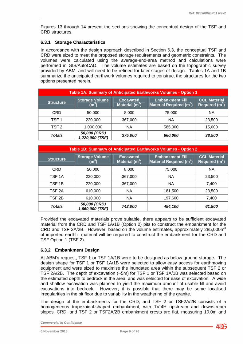
In accordance with the design approach described in Section 6.3, the conceptual TSF and CRD were sized to meet the proposed storage requirements and geometric constraints. The volumes were calculated using the average-end-area method and calculations were performed in GIS/AutoCAD. The volume estimates are based on the topographic survey provided by ABM, and will need to be refined for later stages of design. Tables 1A and 1B summarize the anticipated earthwork volumes required to construct the structures for the two options presented herein.
Table 1A: Summary of Anticipated Earthworks Volumes - Option 1
Structure Storage Volume
(m3)
Excavated Material (m
3)
Embankment Fill Material Required (m
3)
CCL Material Required (m
3)
CRD 50,000 8,000 75,000 NA
TSF 1 220,000 367,000 NA 23,500
TSF 2 1,000,000 NA 585,000 15,000
Totals 50,000 (CRD)
1,220,000 (TSF) 375,000 660,000 38,500
Table 1B: Summary of Anticipated Earthworks Volumes - Option 2
Structure Storage Volume
(m3)
Excavated Material (m
3)
Embankment Fill Material Required (m
3)
CCL Material Required (m
3)
CRD 50,000 8,000 75,000 NA
TSF 1A 220,000 367,000 NA 23,500
TSF 1B 220,000 367,000 NA 7,400
TSF 2A 610,000 NA 181,500 23,500
TSF 2B 610,000 NA 197,600 7,400
Totals 50,000 (CRD)
1,660,000 (TSF) 742,000 454,100 61,800
Provided the excavated materials prove suitable, there appears to be sufficient excavated material from the CRD and TSF 1A/1B (Option 2) pits to construct the embankment for the CRD and TSF 2A/2B. However, based on the volume estimates, approximately 285,000m3 of imported earthfill material will be required to construct the embankment for the CRD and TSF Option 1 (TSF 2). 6.3.2 Embankment Design
At ABM’s request, TSF 1 or TSF 1A/1B were to be designed as below ground storage. The design shape for TSF 1 or TSF 1A/1B were selected to allow easy access for earthmoving equipment and were sized to maximise the inundated area within the subsequent TSF 2 or TSF 2A/2B. The depth of excavation (~5m) for TSF 1 or TSF 1A/1B was selected based on the estimated depth to bedrock in the area, and was selected for ease of excavation. A wide and shallow excavation was planned to yield the maximum amount of usable fill and avoid excavations into bedrock. However, it is possible that there may be some localised irregularities in the pit floor due to variability in the weathering of the granite.
The design of the embankments for the CRD, and TSF 2 or TSF2A/2B consists of a homogeneous trapezoidal-shaped embankment, with 1V:4H upstream and downstream slopes. CRD, and TSF 2 or TSF2A/2B embankment crests are flat, measuring 10.0m and
Ref: 028900REP01 Rev2
Commercial in Confidence
6 November 2013 Page 10 of 26
4.0m wide, respectively (refer Figures 13 & 14). The embankment construction material is based on the anticipated excavated material from the CRD, TSF 1 or TSF 1A/B and mine waste rock (if required) consisting of mostly sandy clay material derived from the weathered bedrock. The anticipated material selection is based on limited geotechnical and geological data, and the excavated material and any required borrow materials to make up shortfalls in quantities must be investigated thoroughly prior to the next stage of design.
As shown in Figures 13 and 14, a key trench below the TSF 2 bunds has been included in the conceptual design to strengthen foundation conditions and reduce seepage potential along the interface between in situ and constructed materials. However, following detailed geotechnical investigation and assessment, different foundation treatments may be considered. 6.3.3 Liner Options
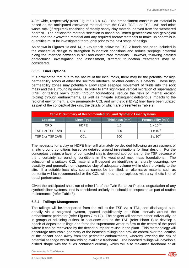
It is anticipated that due to the nature of the local rocks, there may be the potential for high permeability zones at either the soil/rock interface, or other continuous defects. These high permeability zones may potentially allow rapid seepage movement of fluids into the rock mass and the surrounding areas. In order to limit significant vertical migration of supernatant (TSF) or tailings leach (CRD) through foundations, reduce the risks of internal erosion (piping) through embankments, as well as mitigate subsequent deleterious impacts to the regional environment, a low permeability CCL and synthetic (HDPE) liner have been utilized as part of the conceptual designs, the details of which are presented in Table 2.
Table 2: Summary of Recommended Soil and Synthetic Liner Systems
Location Liner Type Thickness (mm) Permeability (m/s)
CRD HDPE 1.5 1 x 10-14
TSF 1 or TSF 1A/B CCL 300 1 x 10⁻⁸
TSF 2 or TSF 2A/B CCL 300 1 x 10⁻⁸
The necessity for a clay or HDPE liner will ultimately be decided following an assessment of in situ ground conditions based on detailed ground investigations for final design. For the conceptual design, a layer of compacted clay is deemed appropriate for the TSF because of the uncertainty surrounding conditions in the weathered rock mass foundations. The selection of a suitable CCL material will depend on identifying a naturally occurring, low plasticity and generally non-dispersive clay of adequate volume within close proximity to the site. If a suitable local clay source cannot be identified, an alternative material such as bentonite will be recommended or the CCL will need to be replaced with a synthetic liner of equal performance. Given the anticipated short run-of-mine life of the Twin Bonanza Project, degradation of any synthetic liner systems used is considered unlikely, but should be inspected as part of routine maintenance (refer Table 3). 6.3.4 Tailings Management
The tailings will be transported from the mill to the TSF via a TDL, and discharged sub-aerially via a spigotted system, spaced equidistantly at ~50m intervals around the embankment perimeter (refer Figures 7 to 12). The spigots will operate either individually, or in groups of adjoining outlets, in sequence around the TSF (refer Photo 1) to develop a beach of deposited tailings and force the supernatant water to flow to the centre of the pond where it can be recovered by the decant pump for re-use in the plant. This methodology will encourage favourable geometry of the beached tailings and provide control over the location of the decant pond away from the perimeter embankments, whereby lowering the risk of potential seepage whilst maximising available freeboard. The beached tailings will develop a dished shape with the fluids contained centrally which will also maximise freeboard at all
Ref: 028900REP01 Rev2
Commercial in Confidence
6 November 2013 Page 11 of 26
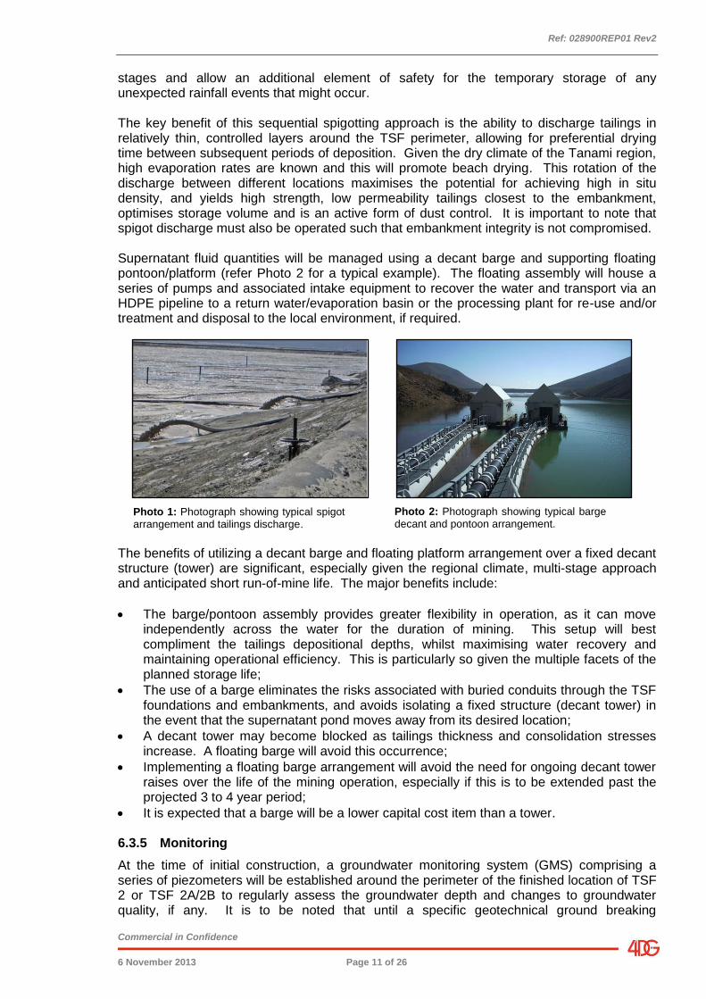
stages and allow an additional element of safety for the temporary storage of any unexpected rainfall events that might occur. The key benefit of this sequential spigotting approach is the ability to discharge tailings in relatively thin, controlled layers around the TSF perimeter, allowing for preferential drying time between subsequent periods of deposition. Given the dry climate of the Tanami region, high evaporation rates are known and this will promote beach drying. This rotation of the discharge between different locations maximises the potential for achieving high in situ density, and yields high strength, low permeability tailings closest to the embankment, optimises storage volume and is an active form of dust control. It is important to note that spigot discharge must also be operated such that embankment integrity is not compromised. Supernatant fluid quantities will be managed using a decant barge and supporting floating pontoon/platform (refer Photo 2 for a typical example). The floating assembly will house a series of pumps and associated intake equipment to recover the water and transport via an HDPE pipeline to a return water/evaporation basin or the processing plant for re-use and/or treatment and disposal to the local environment, if required.
The benefits of utilizing a decant barge and floating platform arrangement over a fixed decant structure (tower) are significant, especially given the regional climate, multi-stage approach and anticipated short run-of-mine life. The major benefits include:
The barge/pontoon assembly provides greater flexibility in operation, as it can move independently across the water for the duration of mining. This setup will best compliment the tailings depositional depths, whilst maximising water recovery and maintaining operational efficiency. This is particularly so given the multiple facets of the planned storage life;
The use of a barge eliminates the risks associated with buried conduits through the TSF foundations and embankments, and avoids isolating a fixed structure (decant tower) in the event that the supernatant pond moves away from its desired location;
A decant tower may become blocked as tailings thickness and consolidation stresses increase. A floating barge will avoid this occurrence;
Implementing a floating barge arrangement will avoid the need for ongoing decant tower raises over the life of the mining operation, especially if this is to be extended past the projected 3 to 4 year period;
It is expected that a barge will be a lower capital cost item than a tower. 6.3.5 Monitoring
At the time of initial construction, a groundwater monitoring system (GMS) comprising a series of piezometers will be established around the perimeter of the finished location of TSF 2 or TSF 2A/2B to regularly assess the groundwater depth and changes to groundwater quality, if any. It is to be noted that until a specific geotechnical ground breaking
Photo 1: Photograph showing typical spigot arrangement and tailings discharge.
Photo 2: Photograph showing typical barge decant and pontoon arrangement.
Ref: 028900REP01 Rev2
Commercial in Confidence
6 November 2013 Page 12 of 26
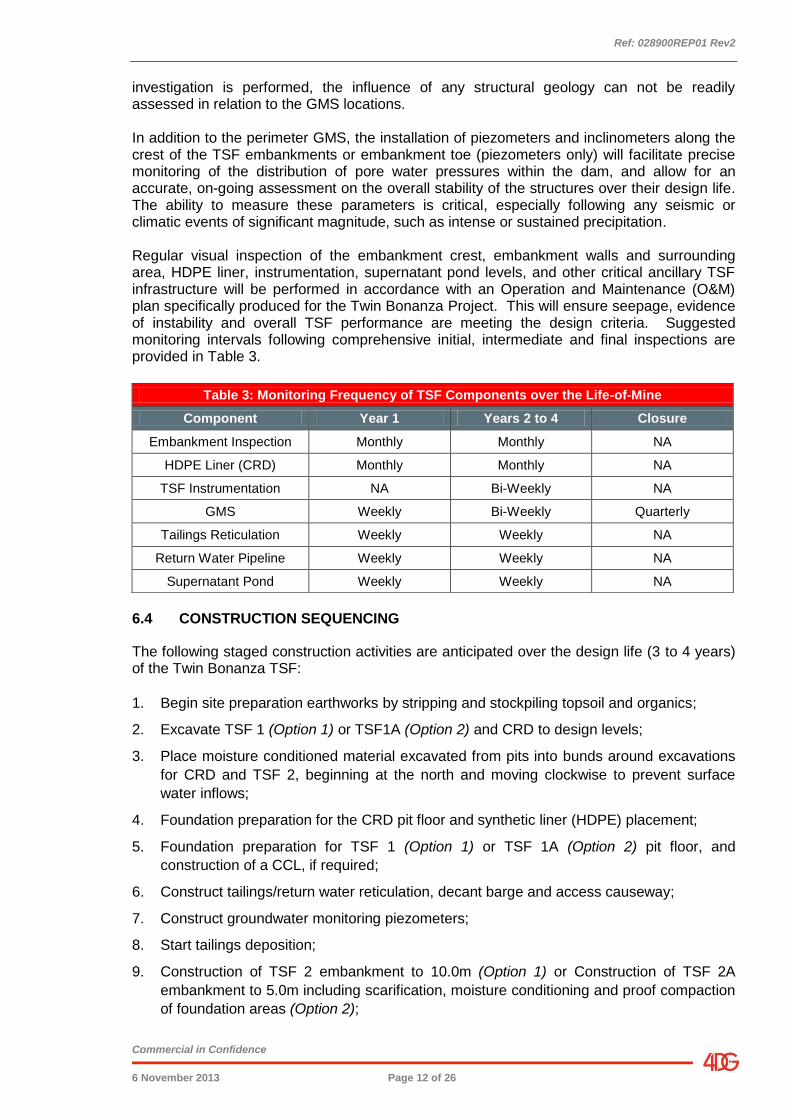
investigation is performed, the influence of any structural geology can not be readily assessed in relation to the GMS locations. In addition to the perimeter GMS, the installation of piezometers and inclinometers along the crest of the TSF embankments or embankment toe (piezometers only) will facilitate precise monitoring of the distribution of pore water pressures within the dam, and allow for an accurate, on-going assessment on the overall stability of the structures over their design life. The ability to measure these parameters is critical, especially following any seismic or climatic events of significant magnitude, such as intense or sustained precipitation. Regular visual inspection of the embankment crest, embankment walls and surrounding area, HDPE liner, instrumentation, supernatant pond levels, and other critical ancillary TSF infrastructure will be performed in accordance with an Operation and Maintenance (O&M) plan specifically produced for the Twin Bonanza Project. This will ensure seepage, evidence of instability and overall TSF performance are meeting the design criteria. Suggested monitoring intervals following comprehensive initial, intermediate and final inspections are provided in Table 3.
6.4 CONSTRUCTION SEQUENCING
The following staged construction activities are anticipated over the design life (3 to 4 years) of the Twin Bonanza TSF:
1. Begin site preparation earthworks by stripping and stockpiling topsoil and organics;
2. Excavate TSF 1 (Option 1) or TSF1A (Option 2) and CRD to design levels;
3. Place moisture conditioned material excavated from pits into bunds around excavations
for CRD and TSF 2, beginning at the north and moving clockwise to prevent surface
water inflows;
4. Foundation preparation for the CRD pit floor and synthetic liner (HDPE) placement;
5. Foundation preparation for TSF 1 (Option 1) or TSF 1A (Option 2) pit floor, and
construction of a CCL, if required;
6. Construct tailings/return water reticulation, decant barge and access causeway;
7. Construct groundwater monitoring piezometers;
8. Start tailings deposition;
9. Construction of TSF 2 embankment to 10.0m (Option 1) or Construction of TSF 2A
embankment to 5.0m including scarification, moisture conditioning and proof compaction
of foundation areas (Option 2);
Table 3: Monitoring Frequency of TSF Components over the Life-of-Mine
Component Year 1 Years 2 to 4 Closure
Embankment Inspection Monthly Monthly NA
HDPE Liner (CRD) Monthly Monthly NA
TSF Instrumentation NA Bi-Weekly NA
GMS Weekly Bi-Weekly Quarterly
Tailings Reticulation Weekly Weekly NA
Return Water Pipeline Weekly Weekly NA
Supernatant Pond Weekly Weekly NA
Ref: 028900REP01 Rev2
Commercial in Confidence
6 November 2013 Page 13 of 26
10. As TSF 1 storage nears the end of its capacity, extend and raise new TDL/return water
reticulation, pontoon bridge and decant barge to expected new supernatant pond
location;
11. Install monitoring instrumentation (inclinometers and piezometers) along the
embankment and external TSF perimeter;
12. Excavate TSF 1B to design levels (Option 2 only);
13. Relocate the existing TDL/return water reticulation, tailings spigotting reticulation,
pontoon bridge and decant barge to expected supernatant pond location of TSF 1B
(Option 2 only);
14. Extend and raise new TDL/return water reticulation, pontoon bridge and decant barge to
expected supernatant pond location (Option 2 only);
15. Cease tailings deposition and cease mining;
16. Closure of TSF (including capping and ongoing monitoring, if required) to meet required
environmental guidelines. 6.5 GEOTECHNICAL ASSESSMENT
6.5.1 General
While this is recognised as being a conceptual design at this stage, and has not had any specific investigation performed to derive in situ or material characteristics, a general analysis has been performed of seepage and slope stability to evaluate the general effectiveness of the proposed liner system and the stability of the TSF and CRD embankments, based on likely material parameters. The analyses were performed on Section B in the TSF, and on Section A in the CRD (refer Figure 13), which are considered the critical sections. The seepage analyses were conducted using SEEP/W and the corresponding slope stability analyses were conducted using SLOPE/W. SEEP/W is a commercially available computer modelling software package that is designed to analyse steady-state and transient seepage under saturated and partially saturated conditions. The limit equilibrium computer program SLOPE/W was used to analyse the global slope stability under the loading conditions defined in the ANCOLD guidelines. The Morgenstern Price Method of Slices was adopted for all analyses and satisfies all required conditions of static equilibrium, including horizontal and vertical force imbalance, and moment imbalance. Circular trial shear surfaces were identified using the iterative search routines in SLOPE/W to locate the theoretical critical shear surface and subsequently the lowest calculated factors of safety (FoS) for the TSF under each loading condition. 6.5.2 Geological Model for Analyses
Due to limited subsurface data available at this stage of the design, assumed values considered to be conservative but realistic were used for the various materials present at the TSF and CRD locations. The material types and layer thicknesses were based on data provided in Appendix 1. The site geometry indicates a relatively flat surface profile consisting of shallow colluvium over residual saprolite, ranging from 2m to 5m depth and generally dipping north to south. Granite bedrock of unknown strength and weathering is anticipated below the surface soils.
Ref: 028900REP01 Rev2
Commercial in Confidence
6 November 2013 Page 14 of 26
6.5.3 Tailings
Based on the information provided by ABM (refer Section 6.3), the tailings for both dams have been analysed as fine grained, silty, slurry of low permeability and with a relatively low shear strength. 6.5.4 Overburden
The surface colluvium and saprolite is anticipated to consist of sandy clays of medium plasticity based on experience with similar materials. Our analysis is based on this material being used to construct the TSF and CRD embankments, and the CCL. Assumed values of shear strength and permeability have been used in our analyses for the in situ foundation material, as well as the reworked embankment fill and the clay liner. 6.5.5 Bedrock
The bedrock at the site is anticipated to be largely granite, based on information provided from ABM (refer Appendix 1) and published geological information. We have assumed that the bedrock is moderately weathered and therefore have estimated a conservatively high permeability value for the seepage analyses. As part of these analyses, bedrock has also been modelled as impenetrable to slope failure. 6.5.6 Model Geometry
Two theoretical two-dimensional models were developed to analyse the seepage and stability of the TSF and the seepage of the CRD. For the analyses, the embankments are comprised of earthfill materials. The foundation is comprised of colluvium/saprolite over granite bedrock.
The embankments are homogenous in composition with upstream and downstream slopes at 1V:4H. The TSF embankment has a maximum height of 10.0m, and a 4.0m wide crest. The CRD has a maximum height of 5.0m, and a 10.0m wide crest.
The foundation material at the TSF and CRD location is approximately 5.0m thick based on bedrock contours provided by ABM Resources.
The TSF (refer Figure 15) was analysed without a liner, and with a 300mm thick CCL. The CRD (refer Figure 16) was analysed without a liner, with a 300mm thick CCL, and with a HDPE Liner.
These designs have been used for our analyses, however, different options such as thicker clay liners, or reworking in situ materials, or the incorporation of different synthetic liners could be considered once site specific information becomes available. 6.6 Seepage Analysis
Seepage analyses were conducted to evaluate the effectiveness of the TSF and the CRD with no liner, a 300mm-thick CCL, and a HDPE Liner (CRD only). The analyses quantified seepage through the base of the TSF and CRD. The transient seepage analyses were modelled using an analysis time of 10 years. This time period was chosen based on the anticipated 3 to 4 year life-of-mine and allowing for post-operations pore water seepage.
The purpose of the conceptual liners is to limit infiltration of tailings pore water into the foundation and limit interaction with groundwater.
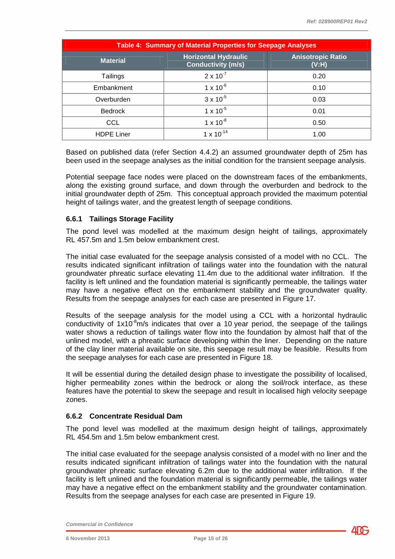
The selected material properties selected for the seepage analyses are provided in Table 4.
Ref: 028900REP01 Rev2
Commercial in Confidence
6 November 2013 Page 15 of 26
Table 4: Summary of Material Properties for Seepage Analyses
Material Horizontal Hydraulic Conductivity (m/s)
Anisotropic Ratio (V:H)
Tailings 2 x 10⁻⁷
0.20
Embankment 1 x 10⁻⁶
0.10
Overburden 3 x 10⁻⁵
0.03
Bedrock 1 x 10⁻⁵
0.01
CCL 1 x 10⁻⁸
0.50
HDPE Liner 1 x 10-14
1.00
Based on published data (refer Section 4.4.2) an assumed groundwater depth of 25m has been used in the seepage analyses as the initial condition for the transient seepage analysis.
Potential seepage face nodes were placed on the downstream faces of the embankments, along the existing ground surface, and down through the overburden and bedrock to the initial groundwater depth of 25m. This conceptual approach provided the maximum potential height of tailings water, and the greatest length of seepage conditions. 6.6.1 Tailings Storage Facility
The pond level was modelled at the maximum design height of tailings, approximately RL 457.5m and 1.5m below embankment crest. The initial case evaluated for the seepage analysis consisted of a model with no CCL. The results indicated significant infiltration of tailings water into the foundation with the natural groundwater phreatic surface elevating 11.4m due to the additional water infiltration. If the facility is left unlined and the foundation material is significantly permeable, the tailings water may have a negative effect on the embankment stability and the groundwater quality. Results from the seepage analyses for each case are presented in Figure 17. Results of the seepage analysis for the model using a CCL with a horizontal hydraulic conductivity of 1x10⁻⁸m/s indicates that over a 10 year period, the seepage of the tailings water shows a reduction of tailings water flow into the foundation by almost half that of the unlined model, with a phreatic surface developing within the liner. Depending on the nature of the clay liner material available on site, this seepage result may be feasible. Results from the seepage analyses for each case are presented in Figure 18. It will be essential during the detailed design phase to investigate the possibility of localised, higher permeability zones within the bedrock or along the soil/rock interface, as these features have the potential to skew the seepage and result in localised high velocity seepage zones. 6.6.2 Concentrate Residual Dam
The pond level was modelled at the maximum design height of tailings, approximately RL 454.5m and 1.5m below embankment crest. The initial case evaluated for the seepage analysis consisted of a model with no liner and the results indicated significant infiltration of tailings water into the foundation with the natural groundwater phreatic surface elevating 6.2m due to the additional water infiltration. If the facility is left unlined and the foundation material is significantly permeable, the tailings water may have a negative effect on the embankment stability and the groundwater contamination. Results from the seepage analyses for each case are presented in Figure 19.
Ref: 028900REP01 Rev2
Commercial in Confidence
6 November 2013 Page 16 of 26
Results of the seepage analyses for the model using a CCL (with a horizontal hydraulic conductivity of 1x10⁻⁸m/s) and separately a HDPE Liner (with a horizontal hydraulic conductivity of 1x10-14m/s) indicates that over a 10 year period, the seepage of the tailings water shows minor infiltration into the foundation with the CCL, and almost no infiltration with the HDPE Liner. Due to the nature of the tailings being stored, we recommend the use of the HDPE Liner to provide the best protection from concentrate residual tailings pore water seepage into the foundation. Seepage results for both liner options analysed are presented in Figures 20 and 21. If an HDPE liner is not used, it will be essential during the detailed design phase to investigate the possibility of localised, higher permeability zones within the bedrock or along the soil/rock interface, as these features have the potential to skew the seepage and result in localised high velocity seepage zones.
6.7 Stability Analysis
Stability analyses were conducted to evaluate the performance of the conceptual embankments under the following static and seismic loading conditions:
Drained;
Undrained;
Pseudo-Static; and
Post-Seismic.
Based on the thickness of the overburden and the height of the proposed completed Stage 2 embankment, Section B (refer Figure 13) through the TSF was selected as the most critical section for the stability analysis. Stability analyses were not conducted on the CRD as the embankment design is considered inherently more stable than the TSF Option 1, having lesser overall height and a significantly wider crest. The material properties selected for the conceptual stability analyses were estimated using typical published values (Reference 11) and our experience with similar projects. The properties of each material used in the stability analyses are summarised in Table 5. The seismic loading of the TSF was analysed using both pseudo-static and post-seismic methods. The post-seismic method was included because tailing materials are typically considered liquefiable during seismic shaking. ANCOLD (Reference 1) recommends the pseudo-static method developed by the US Army Corp of Engineers (USACE) (1984) (Reference 10) as the preferred method of pseudo-static analysis and this approach has been adopted for this analysis. The peak ground acceleration (pga) selected for the pseudo-static analysis is 0.09g, based on AS 1170.4, (Reference 2). For the analysis, 0.75pga was modelled, based on the USACE recommendation of using between 0.50 and 0.75pga. The TSF stability is considered acceptable if the pseudo-static factor of safety is greater than 1.0, which typically indicates that the anticipated seismic displacement will be less than 0.5m. Undrained shear strength values were reduced by 20% for the embankment, CCL, and the overburden materials to account conceptually for increased pore pressures and shear softening during seismic shaking. The tailings shear strength was reduced to zero due to their propensity to liquefy. Published values for the internal friction angle of liquefied tailings typically range from 4 to 10 degrees with zero cohesion during post-seismic loading conditions. However, a shear strength value of zero was used for this analysis to account for the lack of data on the residual shear strength of the tailing material at this time.
Ref: 028900REP01 Rev2
Commercial in Confidence
6 November 2013 Page 17 of 26
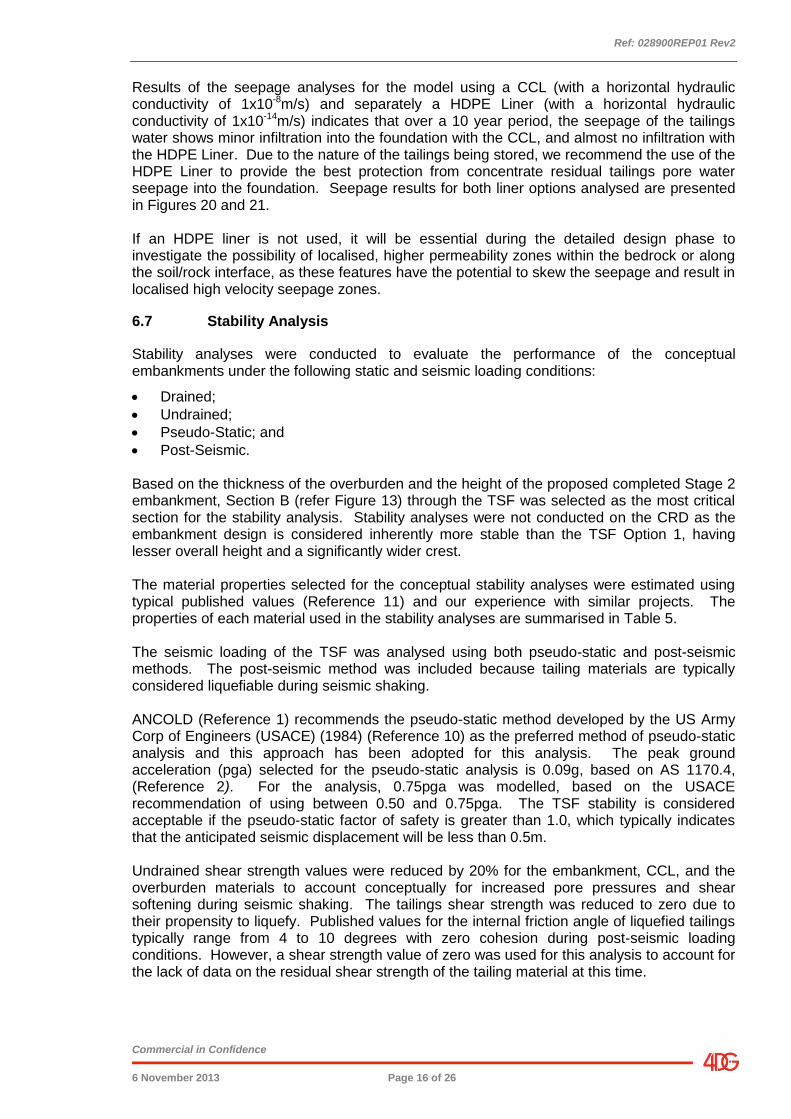
Table 5: Summary of Material Properties for Stability Analyses
Type of Materials Unit Weight
(kN/m3)
Cohesion (kPa)
Friction Angle (deg)
Remarks
Tailings 16
12 0 Undrained
5 15 Drained
10 0 Pseudo-static
0 0 Post-seismic
Embankment 19
50 0 Undrained
15 25 Drained
40 0 Pseudo-static
40 0 Post-seismic
Overburden 17
50 0 Undrained
10 20 Drained
40 0 Pseudo-static
40 0 Post-seismic
Compacted Clay Liner
19
50 0 Undrained
15 25 Drained
40 0 Pseudo-static
40 0 Post-seismic
Figures 22 through 25 graphically present the stability analyses results, showing the potential critical failure surface for each loading condition.
Table 6 presents a summary of the stability analysis results for each loading condition.
Table 6: Summary of Stability Analysis Results
Case Recommended Factor of
Safety (ANCOLD) Calculated FoS
Undrained 1.3 2.0
Drained 1.5 2.3
Pseudo-Static 1.0 1.2
Post-Seismic 1.1 1.6
The results indicate an acceptable FoS for each loading condition based on ANCOLD guidelines. The results of the stability analyses indicate that the FoS of the TSF under static loading was greater than 1.5 for long-term loading condition and greater than 1.3 for the short-term undrained loading condition. These results are deemed acceptable for the present analysis due to the conceptual nature of the assessment, and the general lack of factual data. It may be possible to fine-tune the embankment configuration following design investigations and with a greater understanding of in situ and physical properties of all materials.
The results of the pseudo-static and post-seismic stability analyses indicate that the dam will have a factor of safety of 1.2 and 1.6 respectively, suggesting that the dam will not likely suffer significant deformations under design seismic loading. Therefore the stability of the conceptual TSF meets the design standards recommended by ANCOLD Guidelines.
Ref: 028900REP01 Rev2
Commercial in Confidence
6 November 2013 Page 18 of 26
6.7.1 Freeboard Calculations
Based on the ANCOLD Guidelines (Reference 1), the structure is considered a “No-Spill Allowance” structure with a high to extreme consequence category for the design flood. Based on the guidelines, the Probable Maximum Flood (PMF) was used to select the required freeboard allowance. The proposed structure will be a “Paddock Dump” style structure therefore the watershed into the TSF will only occur from precipitation within the TSF catchment. The Probable Maximum Precipitation (PMP) was estimated using the Generalised Short-Duration Method (Reference 8) based on the requirements for the Commonwealth Bureau of Meteorology. The results indicate that the PMP for the TSF will be approximately 820mm for a 5-hour storm event assuming a downpour resulting from a tropical depression that has swung inland. Using a runoff coefficient of 1, the freeboard required for the TSF is ~1.0m with an additional 500mm for wave run-up. A spillway is required by the ANCOLD guidelines for “No-Spill Allowance” structures. Accordingly, a spillway has been incorporated into the conceptual design, with the spillway invert located 500mm below the crest level and the supernatant pond to be maintained at least 1.0m below the spillway invert. 6.8 END OF OPERATIONAL LIFE CLOSURE
The primary rehabilitation closure objective for the Twin Bonanza TSF is to design and construct an engineered cover system that ensures:
1. Environmentally safe, long term containment of the tailings;
2. Establishment of an aesthetically acceptable landform to meet local, social and Territorial Authority agreements; and
3. Promotes land use sustainability.
In order to best achieve these objectives, it is expected that non-hazardous soil and waste rock materials excavated during the active mining phase of the operation will be identified and stockpiled for use as capping material. A surface water management plan will be designed such that the regional arid climate, local drainage characteristics of the site and water demands of the area are all carefully evaluated prior to construction.
To the extent prudent engineering and best practice are adopted during design and construction of the cover system, no adverse effects to human health and safety, regional fauna, flora or water quality are expected. The key post-closure risks that need to be addressed include:
Embankment stability;
Surface water management;
Seepage;
Dust control;
Impacts to the Environment; and Human Health and Safety.
It is important to note that due to the relatively high rate of tailings deposition anticipated during the short life-of-mine (TSF rate of rise), the time required to close the facility will be largely determined by the rate at which the tailings can be effectively dewatered to promote consolidation. The implementation of a dual TSF cell configuration (Option 2) will help shorten this timeframe and also allow for progressive rehabilitation of the site.
In the event that temporary closure of the TSF is required, pending the duration, a generally cohesive soil will need to be placed across the facility. Particular attention must be paid to
Ref: 028900REP01 Rev2
Commercial in Confidence
6 November 2013 Page 19 of 26
the moisture content and level of consolidation that the tailings have undergone before any trafficking of low ground pressure machinery can be considered for earthworks. Careful management of the supernatant pond and tailings beaches leading up to closure will allow for optimised drying of the tailings and a carefully staged construction approach. Option 2 will again assist in this regard. Critical features of the proposed closure strategy developed for the Twin Bonanza TSF include:
Constructing an engineered cap across the TSF and CRD footprints. This cap will limit surface water infiltration, prevent episodic dust pollution and provide a suitable medium for vegetation regrowth;
The placement of topsoil and native low lying grass seed will expedite site rehabilitation and minimise erosion. Over time it is expected that low-lying native shrubs and shallow rooted trees will become established.
Constructing a surface water management system that effectively discharges rainfall to the surrounding environment in a controlled manner. The method for handling this water may vary over the closure period of the TSF, and assumes that further treatment of the water is not required.
Decommissioning (removal and disposal) of the TSF spillway, pumps, foundations and pipeline infrastructure in accordance with the relevant standards and government regulations will be required.
Monitoring the groundwater quality and levels around the perimeter of the TSF and CRD in accordance with the Operations and Maintenance recommendations and regulatory guidelines, to ensure that any runoff or seepage is not adversely impacting the environment.
6.9 CONSTRUCTION CONSIDERATIONS AND DESIGN IMPLICATIONS
Based on the limited data provided (refer Appendix 1), it is anticipated that excavation of surface materials and weathered rock to depths between 2.0m (CRD) and 5.0m (TSF 1 or TSF 1A/1B) for foundation construction can generally be effected with conventional earthmoving equipment such as dozers, scrapers, and hydraulic excavators. It should be noted that there is potential for encountering abrupt changes in “hard rock” depth across the site, as well as localised granite corestones within more weathered materials. The natural soil and/or weathered rock in the area of the proposed TSF should provide a suitable strength foundation to support the proposed embankments, and significant consolidation of foundation material is not anticipated. Scarifying, moisture conditioning and proof compaction of the final exposed subgrade within the footprint of the CRD and TSF 1 or TSF 2 is expected to mitigate downward migration of water. It is important to note that the soils at the site will likely require the addition of water in order to achieve optimum compaction during earthworks, and should be closely monitored at the time of construction. Natural soils at the TSF site are not expected to be highly compressible in nature, and the presence of any significant layers of topsoil, or organic-rich material is considered unlikely. With the exception of some disturbed zones around areas of previous development (existing bulk sample processing plant and TSF), areas of fill are not expected to be encountered either. It is generally not good engineering practice to found on non-engineered fill, and therefore, it is suggested that prior to any construction along the northern edge of the CRD, particular attention be given to ensuring that any areas of fill are identified. If fill is encountered, it should be removed, replaced with clean, approved materials and compacted in accordance with good engineering practice. Given the intended purpose of the TSF, the excavated material from the CRD and TSF 1 or TSF 1A/1B should be a suitable borrow material for construction of the proposed
Ref: 028900REP01 Rev2
Commercial in Confidence
6 November 2013 Page 20 of 26
embankments following stripping of vegetation and root-affected soil. A piping risk assessment and thorough suite of laboratory tests (refer Section 7.0) will be required to verify construction material suitability and the potential erosional qualities of tailings geochemistry on foundations and embankments over the life of the operation. It is important to note that no geotechnical data for the southern half of the proposed TSF site is believed to exist. This geological model assumes that the interpretations previously made by ABM and other third parties are accurate and reasonable, and that the footprint of the proposed TSF is underlain by similar lithologies to the bulk sample processing plant and TSF. Detailed investigations during the design phase will provide data on in situ material characteristics, permeability, and potential properties as fill.
7.0 RECOMMENDATIONS
The present design is a conceptual one, to allow a basic costing and to assess preliminary regulatory approvals. To best expedite operation of an effective, cost-efficient and environmentally responsible TSF, a number of critical engineering inputs require information in order to refine the geological/geotechnical model and accurately characterize the site for final design.
The data required includes:
1. Accurate historical rainfall data for the region;
2. Records of water level and quality from local water bores;
3. Details of the proposed processing methodology of the gold ore and the chemicals likely
to remain in the supernatant waters;
4. A topographical survey of the proposed TSF footprint and surrounding area; and
5. A specific geotechnical ground breaking investigation, comprising:
A site assessment and geological mapping to examine the in situ characteristics of rock and soil materials;
Exploratory drilling and test pitting (for TSF site characterization, material permeability and identification of potential borrow sources and characteristics);
In situ testing including water pressure (packer) testing and falling/constant head permeability testing, shear vane, dynamic cone penetrometer and SPT;
Laboratory Testing (Moisture Content, Particle Size Distribution, Atterberg limits, Compaction, CBR, Triaxial, Point Load, Pinhole Dispersion, Emerson Class, Slake Durability and a comprehensive Geochemical Suite, including groundwater and anticipated plant water sources); and
Geotechnical Analysis (Seepage, Slope Stability, Piping Risk Assessment).
8.0 LIMITATIONS
This design report for a conceptual tailings storage facility is based solely on the results of a limited geotechnical desktop study carried out by 4DG between August and October 2013. This report has been prepared for the particular project described to us (Twin Bonanza Mine TSF) and its extent is limited to the scope of work agreed between the Client (ABM) and 4DG. Data from this report shall not be separated, copied in part or misrepresented in any circumstance. No responsibility is accepted by 4DG or its Directors, staff or employees for the accuracy of information provided to 4DG by third parties and/or the use of any part of this report in any other context or for any other purposes.

Ref: 028900REP01 Rev2
Commercial in Confidence
6 November 2013 Page 21 of 26
The recommendations, opinions and conceptual design elements contained in this report are based on our interpretation of the site, information from geological maps, and from the data obtained from ABM. The inherent uncertainty in the geological findings presented herein must be recognised. Inferences about the nature and continuity of subsurface conditions away from and beyond the exploratory test locations are made, but cannot be guaranteed. It must be noted that the subsoil profiles indicated in this report represent the subsurface conditions at the locations where previous investigations (completed by others and of limited geotechnical value) were undertaken and, as such, only represent a proportion of the proposed TSF area. During any future investigations and construction, a competent geotechnical engineer or engineering geologist should check and verify whether the actual subsoil conditions encountered at the site are compatible with the assumptions made in this report. In all circumstances, if variations in the subsurface conditions occur which differ from those assumed to exist, then the matter should be referred back to 4DG. It is recommended that any plans and/or specifications which relate to this geotechnical report be reviewed by 4DG to verify that the intent of the data presented or recommendations contained in this report are reflected in the design. This report is for use by ABM only. It should not be used or relied upon by any other person or entity or for any other project, with the exception that the relevant Territorial Authority or regulating body may rely on it for the purpose of processing preliminary consent applications.
Ref: 028900REP01 Rev2
Commercial in Confidence
6 November 2013 Page 22 of 26
9.0 REFERENCES
1. ANCOLD, 2012, Guidelines on Tailings Dams, Planning, Design, Construction, Operation and Closure.
2. AS 1170.4-1993 - Minimum Design Loads on Structures - Part 4 - Earthquake Loads
3. Boucher R.K., Etheridge M.A, Hill P., and Baga L. (2013). New Structural Observation and Tectonic Model for Part of the Granites-Tanami Orogen. Australian Institute of Geoscientists News, Quarterly Newsletter No.113 (August 2013), p.1-2,4-9.
4. Bureau of Mineral Resources, Geology and Geophysics 1:250,000 Scale Geological Sheet (SF/52-3) of the Granites, Northern Territory, First Edition, 1926.
5. Duncan, J., Wright, S., 2005, "Soil Strength and Slope Stability", John Wiley and Sons, Inc.
6. EcOz Environmental Services, 2012, Dry Season Fauna Survey Old Pirate Prospect, Tanami Desert, N.T - Prepared for ABM Resources.
7. Hodgson I.M., 1976, 1:250,000 Geological Series - Explanatory Notes, The Granites (Sheet SF/52-3): Northern, Department of National Resources - Department of Mineral Resources, Geology and Geophysics, Australian Government Publishing Services, Canberra.
8. Hydrometerological Advisory Services, 2003, Estimation of Probable Maximum Precipitation in Australia: Generalised Short - Duration Method, P.22. Commonwealth of Meteorology.
9. Magee J., 2009/03, Palaeovalley Groundwater Resources in Arid and Semi-Arid Australia - A Literature Review, p.84-92. Geoscience Australia.
10. United States Army Corps of Engineers (USACE), “Slope Stability Manual EM-1110-2-1902”, Washington, D. C.: Department of the Army, Office of the Chief of Engineers, 1982.
11. United States Bureau of Reclamation, 1987, "Design of Small Dams", 3rd Revision.
Ref: 028900REP01 Rev2
Commercial in Confidence
6 November 2013 Page 23 of 26
10.0 GLOSSARY
Accretional: The process of accretion in which there is gradual enlargement of a land area by the deposition of sediment by rives or streams. Achaean: Geologic period covering the time span between 4,000 Ma and 2,500 Ma. Aeolian/Aeolian Deposit: Sediment (detrital material) deposited by wind such as dunal sand. Alluvium and Alluvial Deposits: Sediment (detrital material) deposited by running water, such as rivers, streams and creeks. Arenite: Consolidated sedimentary rock with sand size particles, regardless of composition. Borrow: An area where material is sourced to be used as fill for engineering purpose. Basalt: A fine grained igneous rock dominated by dark coloured minerals, consisting of plagioclase feldspars. Calcrete: A calcium precipitate that can form crusts, nodules, cavities and cementation of soils materials such as sand and gravel. Cambrian: Geologic period covering the time span between 570 Ma and 500 Ma. Cenozoic: Geologic period covering the time span between 65 Ma and the present (also known as Cainozoic and Kainozoic). Chert: Granular cryptocrystalline silica, similar to flint but usually light in colour. Claystone: Indurated clay, consisting of predominately fine grained material a majority of which is clay mineral. Colluvium/Colluvial: A general term applied to any loose heterogeneous soil and/or rock material deposited by sheet wash or slow downslope creep. Concentrate Residual Dam: A designed bunded area to contain contaminated materials and liquids. Cretaceous: Geologic period covering the time span between 135 Ma and 65 Ma. Decant Barge: A floating platform that houses pumps used to reclaim water from the supernatant/decant pond back to the processing plant or holding ponds. Decant Pond: A pond usually holding a clear liquid that overlies material deposited by settling, precipitation, or centrifugation. Diagenically: A process that occurs due to diagensis. Diagensis: Any biological, chemical and/or physically change that occurs to a sediment, post deposition. Ephemeral: An ephemeral water body is a wetland, spring, stream, river, pond or lake that only exists for a short period following precipitation or snowmelt. Ferricrete: A conglomerate consisting of surficial sand and gravel cemented into a hard mass by iron oxide derived from the oxidation of percolating solutions of iron salts.
Ref: 028900REP01 Rev2
Commercial in Confidence
6 November 2013 Page 24 of 26
Fluviatile: Pertaining, belonging to or peculiar to rivers, in particular with respect to physical products of the river’s processes such as sedimentation. Freeboard: The vertical difference between a dams crest height and that of the reservoir body. Geotextile: Manmade fabrics used in engineering with soil material that aids in numerous applications including, separation, filtering, drainage, erosion protection, permeability etc. Granite: Coarse grained igneous rock dominated by light coloured minerals, consisting of about 50 percent orthoclase, 25 percent quartz, and balance of plagioclase feldspars and ferromagnesian silicates. Greywacke: Generally a sandstone generally exhibiting graded bedding sequences associated with marine sedimentary facies, deposited by submarine turbidity currents. Gypsum: A common evaporate mineral with chemical structure - CaSO4.2H2O. Halite: The most abundant evaporate mineral with chemical structure NaCl. Also referred to as common salt or rock salt. Inclinometer: An instrument used to measure the angle an object makes with the vertical. Also a geotechnical instrument installed in a borehole to measure the stability or movement of a slope based on its movement from the vertical axis. Interglacial: Time between periods of glaciation, when the earth has limited ice coverage. Ipswichian (Eemian): An interglacial period between the age of 125,000 years to 70,000 years ago. Lacustrine: Pertaining, inhabiting, origination or produced by lakes. Lateritic: Pertaining to the iron rich, silica poor, upper horizon of intensely weathered regolith found in tropical climates. Lithology: A description, characterisation, and nomination, based on colour, grain size and composition. Metamorphic: Any rock derived from pre-existing rocks by mineralogical, chemical, and/or structural changes. Metamorphosed: A rock that has undergone some level of metamorphic alteration. Miocene: Geologic period covering the time span between 23 Ma and 5 Ma. Mudstone: Fine grained, detrital sedimentary rock made up of silt and clay sized particles. Orogeny: The process forming mountainous terrain and is responsible for the rocks in these mountains being deformed. Palaeochannels: Ancient channels no longer in use and generally infilled and not present on the present day ground surface. Palaeodrainage: Ancient drainage routes no longer in use and generally infilled and not present on the present day ground surface.
Ref: 028900REP01 Rev2
Commercial in Confidence
6 November 2013 Page 25 of 26
Palaeo-tributaries: Ancient river tributaries no longer in use and generally infilled and not present on the present day ground surface. Palaeovalley: Ancient valley structure no longer in use and generally infilled and not present on the present day ground surface. Palaeozoic: Geologic period covering the time span between 590 Ma and 250 Ma. Phyllitic: A rock with Phyllite type structure. Phyllite: Clayey metamorphic rock with rock cleavage intermediate between slate and schist. Piedmont/ Piedmont Deposit: Situated or formed at the base of a mountain. A deposit formed at the base of a mountain. Porphyritic: The texture of an igneous rock in which larger crystals (phenocrysts) are set in a finer groundmass, either crystalline or glassy. Porphyry: An igneous rock with >25% phenocrysts by volume. Quartz: A hard silicate mineral, SiO2, composed exclusively of silicon-oxygen tetrahedra, with all oxygens joined in a three-dimensional network. Quartzose: Containing quartz as a principal constituent; applied to sediments and sedimentary rocks (e.g., sands and sandstones) consisting chiefly of quartz. Quaternary: Geologic period covering the time span between 2 Ma and the present. Sandstone: Detrital sedimentary rock formed by cementation of individual grains of sand size and commonly composed of mineral quartz. Saprolite: Soft earthy, clay-rich deposit composed of completely decomposed rock occurring in situ by chemical processes, generally red-brown. Scarifying: To roughen or break up the ground surface. Schist: Metamorphic rock dominated by fibrous or platy minerals. Schistose: Medium to coarse grained metamorphic rocks composed of laminated, often flaky parallel layers of mainly micaceous minerals. Sedimentary: Formed by the deposition of sediment. Shale: Fine grained, detrital sedimentary rock made up of silt and clay sized particles. Contains clay minerals as well as particles of quartz, feldspar, calcite, dolomite, and other minerals. Distinguished from mudstone by presence of fissility. Silcrete: A hard surface deposit comprising sand and gravel cemented together by opal, chert or quartz, formed by chemical weathering and water evaporation in semi-arid climates. Siltstone: An indurated silt having the texture and composition of shale but lacking its fine lamination or fissility; a massive mudstone in which the silt predominates over clay. Spigot: Outflow valve for inflow of tailings.
Ref: 028900REP01 Rev2
Commercial in Confidence
6 November 2013 Page 26 of 26
Standpipe Piezometer: An instrument for the measurement of groundwater and water table levels, using slotted pipe at in zones of influence and solid pipe, generally constructed. Strata: Geologic material layer. Supernatant: The usually clear liquid lying above a solid residue after crystallization, precipitation, or centrifugation. Syenogranite: Type of granite that is generally felsic - with predominately alkaline feldspar. Tailings: The waste material associated with the separation of ore from the parent body. Tailings Liquor: Liquefied or liquid bound waste material associated with the separation of ore from the parent body. Tertiary: Geologic period covering the time span between 65 Ma and 2 Ma. Turbidite: Deposit due to current caused by excess density due to the suspended load of sediment (turbidity currents). These currents flow downslope at high speeds and spread along the horizontal, all in a submarine environment. Weathering: Destructive natural processes that cause the degradation of rocks without transport processes.

Ref: 028900REP01 Rev2
Commercial in Confidence
6 November 2013 FIGURES
FIGURES
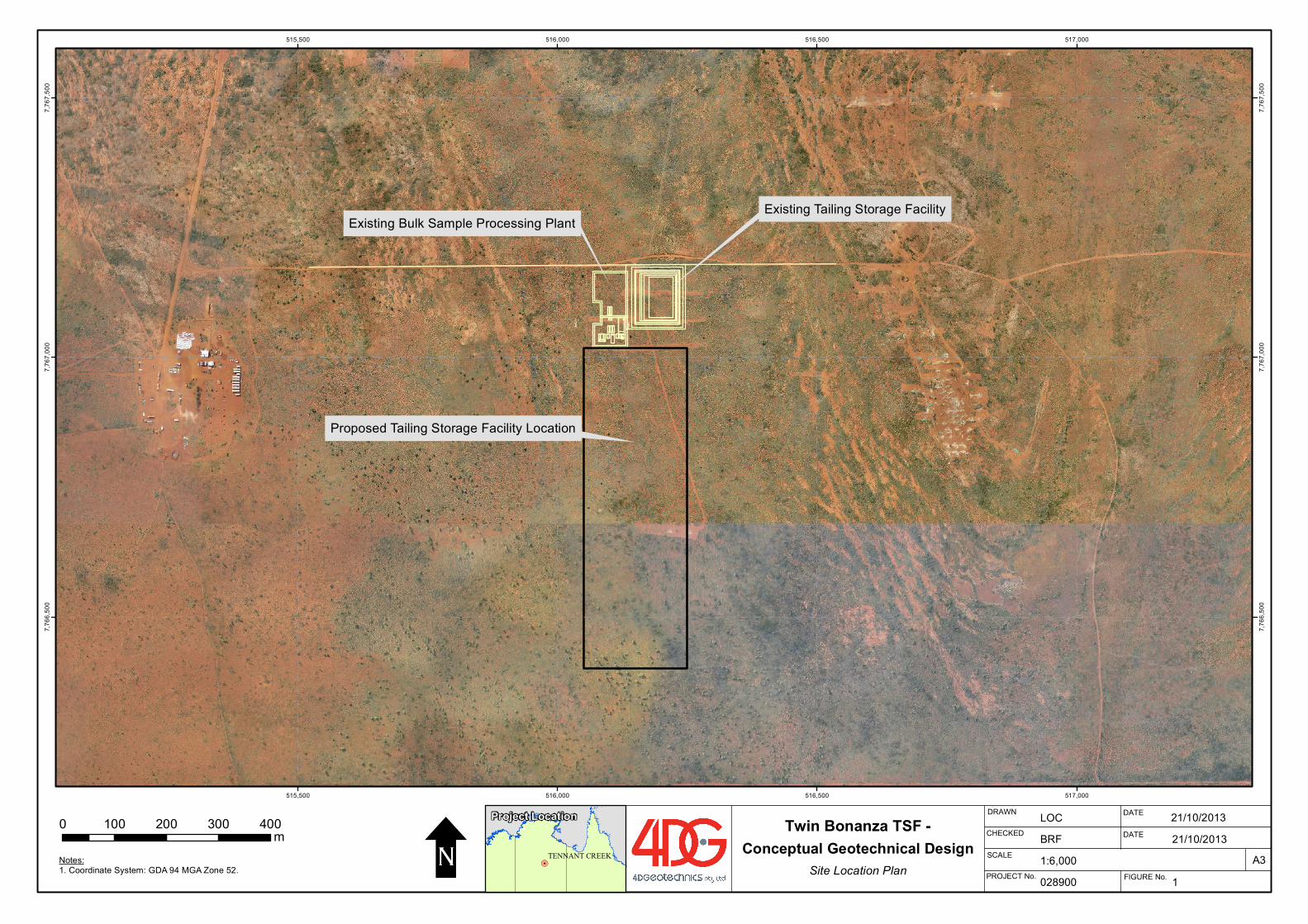
Notes: 1. Coordinate System: GDA 94 MGA Zone 52. !.
TENNANT CREEK
Project Location DRAWNTwin Bonanza TSF -
A3
CHECKED
PROJECT No.
SCALE
DATE
DATE
FIGURE No.Site Location Plan028900
LOC
1
Conceptual Geotechnical Design
515,500
515,500
516,000
516,000
516,500
516,500
517,000
517,000
7,766
,500
7,766
,500
7,767
,000
7,767
,000
7,767
,500
7,767
,500
1:6,000
0 100 200 300 400m U BRF 21/10/2013
Proposed Tailing Storage Facility Location
Existing Tailing Storage FacilityExisting Bulk Sample Processing Plant
21/10/2013
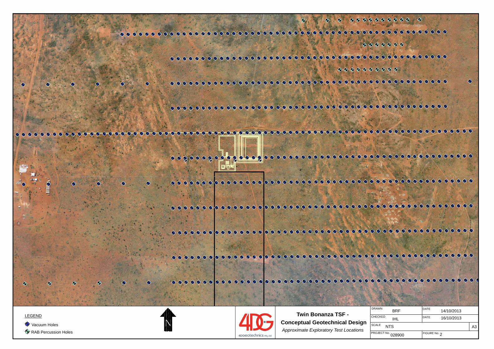
DATE
DATE
FIGURE No.028900
BRF
2
DRAWN
A3
CHECKED
PROJECT No.
SCALE NTS
IHLTwin Bonanza TSF -
Conceptual Geotechnical DesignApproximate Exploratory Test Locations
LEGEND
Vacuum Holes
RAB Percussion Holes
14/10/2013
16/10/2013
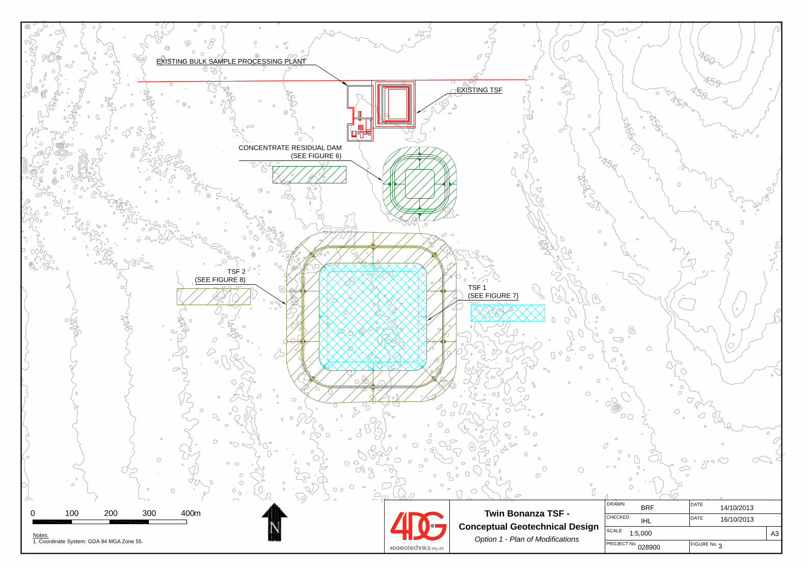
460
459458457
456455454
453
452
451
450
449
449
448
447
446445
448447446445
DATE
DATE
FIGURE No.028900
BRF
3
DRAWN
A3
CHECKED
PROJECT No.
SCALE 1:5,000
IHL
Notes: 1. Coordinate System: GDA 94 MGA Zone 55.
0 100 200 300 400m
EXISTING BULK SAMPLE PROCESSING PLANT
CONCENTRATE RESIDUAL DAM(SEE FIGURE 6)
TSF 2(SEE FIGURE 8)
TSF 1(SEE FIGURE 7)
EXISTING TSF
14/10/2013
16/10/2013Twin Bonanza TSF -
Conceptual Geotechnical DesignOption 1 - Plan of Modifications
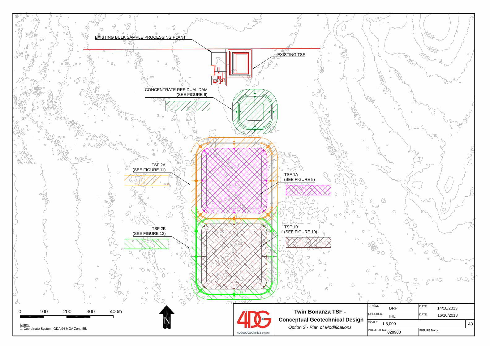
460
459458457
456455454
453
452
451
450
449
449
448
447
446445
448447446445
DATE
DATE
FIGURE No.028900
BRF
4
DRAWN
A3
CHECKED
PROJECT No.
SCALE 1:5,000
IHL
Notes: 1. Coordinate System: GDA 94 MGA Zone 55.
0 100 200 300 400m
EXISTING BULK SAMPLE PROCESSING PLANT
CONCENTRATE RESIDUAL DAM(SEE FIGURE 6)
TSF 2A(SEE FIGURE 11)
TSF 1A(SEE FIGURE 9)
EXISTING TSF
TSF 2B(SEE FIGURE 12)
TSF 1B(SEE FIGURE 10)
14/10/2013
16/10/2013Twin Bonanza TSF -
Conceptual Geotechnical DesignOption 2 - Plan of Modifications
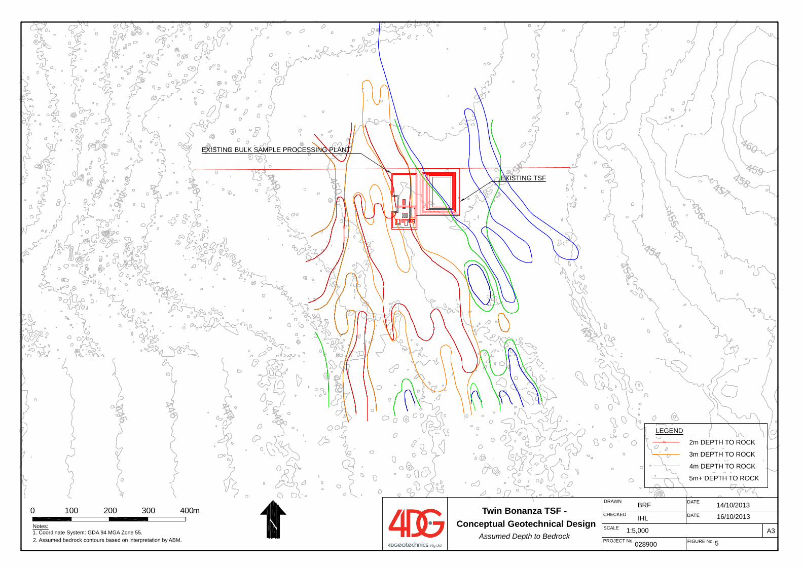
455
449
454
453
452
451
450449
448
459458
456
457
460
448
447
446445
447446445
DATE
DATE
FIGURE No.028900
BRF
5
DRAWN
A3
CHECKED
PROJECT No.
SCALE 1:5,000
IHLNotes: 1. Coordinate System: GDA 94 MGA Zone 55.
0 100 200 300 400m
2. Assumed bedrock contours based on interpretation by ABM.
LEGEND
2m DEPTH TO ROCK
3m DEPTH TO ROCK
4m DEPTH TO ROCK
5m+ DEPTH TO ROCK
EXISTING BULK SAMPLE PROCESSING PLANT
EXISTING TSF
14/10/2013
16/10/2013Twin Bonanza TSF -
Conceptual Geotechnical DesignAssumed Depth to Bedrock
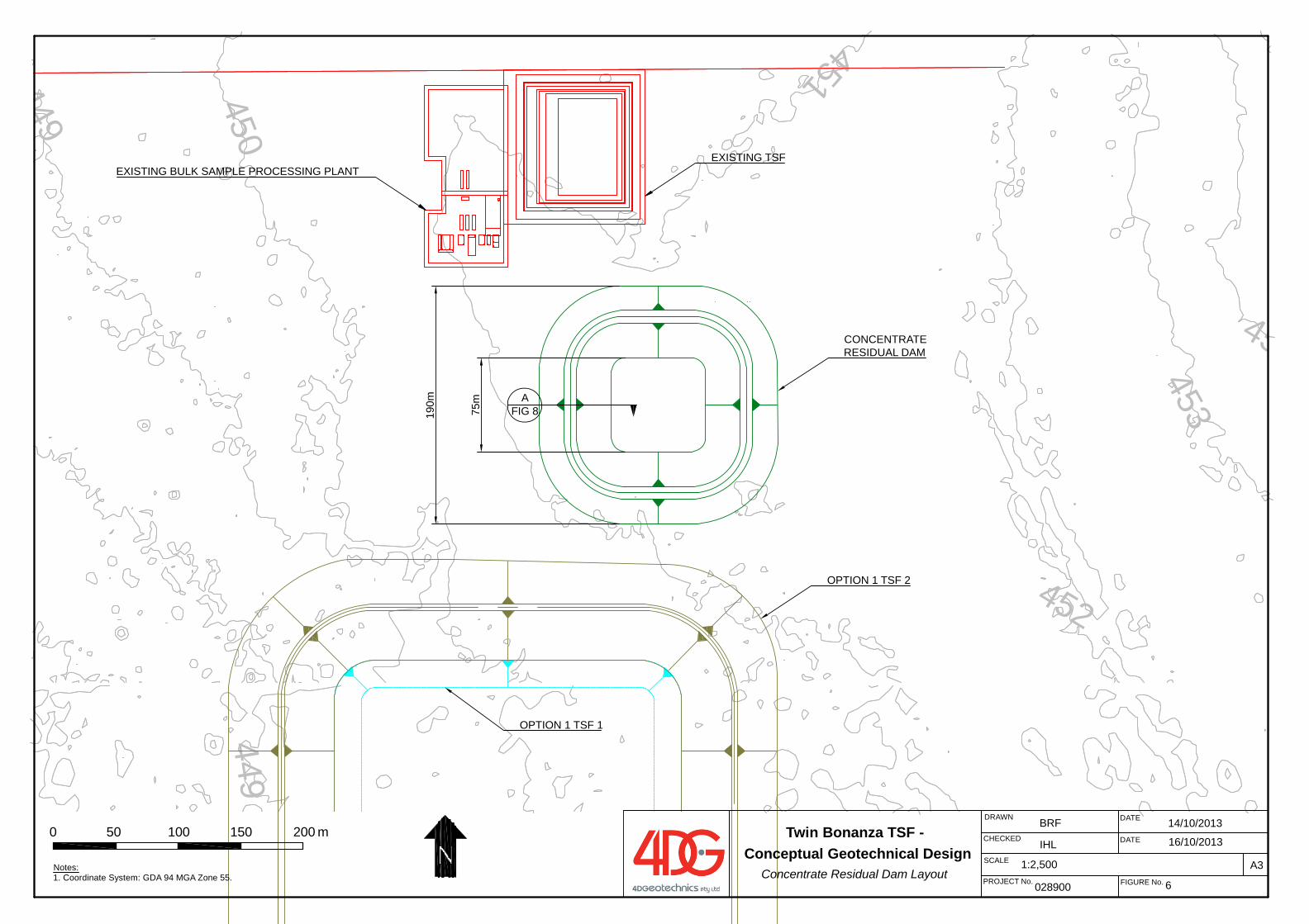
45
453
452
451
450
449
449
DATE
DATE
FIGURE No.028900
BRF
6
DRAWN
A3
CHECKED
PROJECT No.
SCALE 1:2,500
IHL
Notes: 1. Coordinate System: GDA 94 MGA Zone 55.
0 50 100 150 200 m
EXISTING BULK SAMPLE PROCESSING PLANTEXISTING TSF
190m A
FIG 8
CONCENTRATERESIDUAL DAM
OPTION 1 TSF 2
75m
OPTION 1 TSF 1
14/10/2013
16/10/2013Twin Bonanza TSF -
Conceptual Geotechnical DesignConcentrate Residual Dam Layout
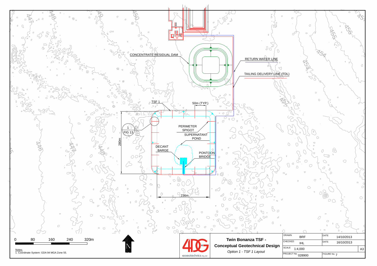
455
449
454
453
452
450449
448
456
457
448
447
446445
447446
DATE
DATE
FIGURE No.028900
BRF
7
DRAWN
A3
CHECKED
PROJECT No.
SCALE 1:4,000
IHL
Notes: 1. Coordinate System: GDA 94 MGA Zone 55.
0 80 160 240 320m
236m
280m
DECANT BARGE
PONTOONBRIDGE
PERIMETER SPIGOT
50m (TYP.)
RETURN WATER LINE
TAILING DELIVERY LINE (TDL)
SUPERNATANT POND
1FIG 13
CONCENTRATE RESIDUAL DAM
TSF 1
14/10/2013
16/10/2013Twin Bonanza TSF -
Conceptual Geotechnical DesignOption 1 - TSF 1 Layout
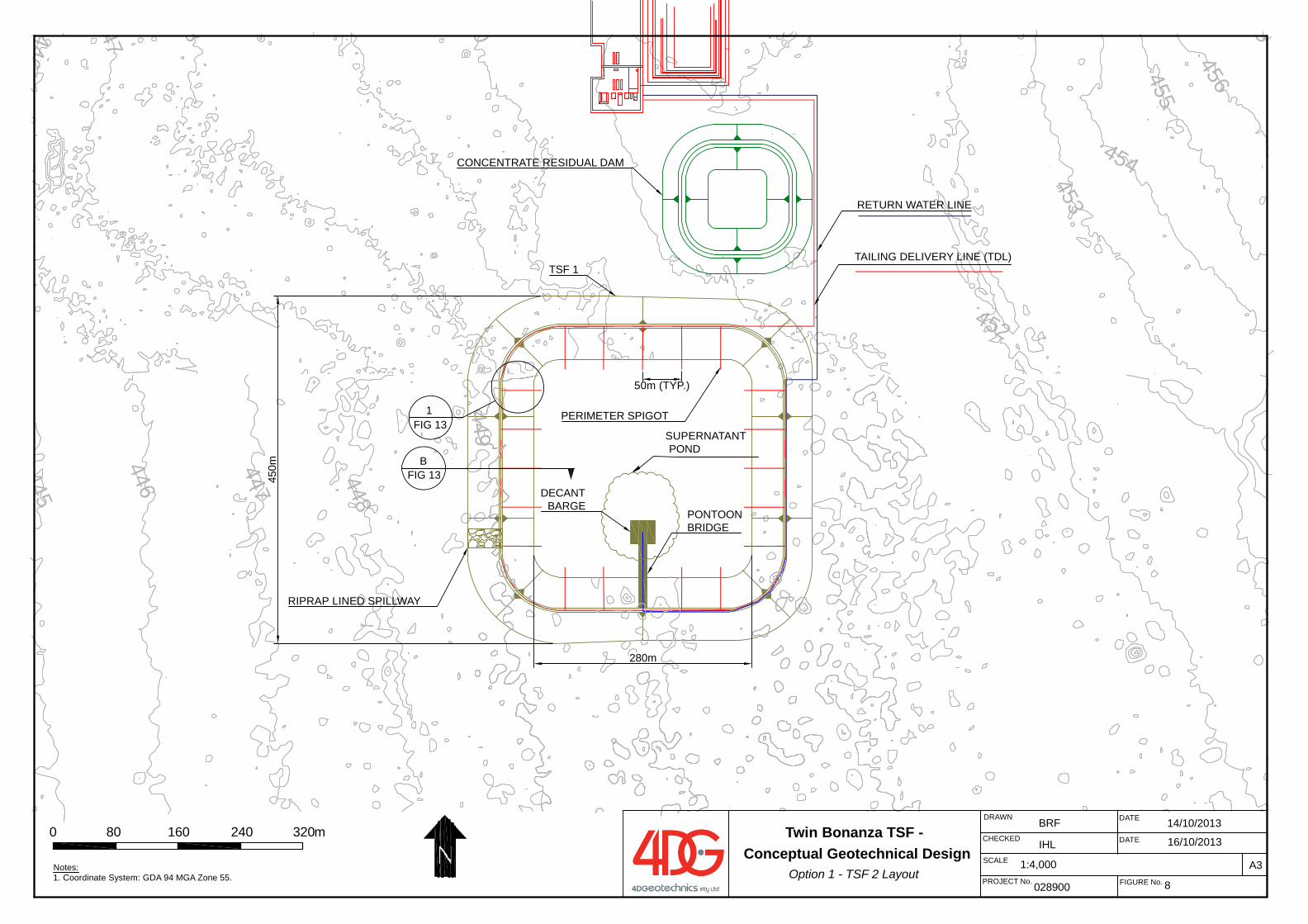
455454
453
452
0449
448
456
4578
447
446445
47446
DATE
DATE
FIGURE No.028900
BRF
8
DRAWN
A3
CHECKED
PROJECT No.
SCALE 1:4,000
IHL
Notes: 1. Coordinate System: GDA 94 MGA Zone 55.
0 80 160 240 320m
SUPERNATANT POND
450m B
FIG 13
RIPRAP LINED SPILLWAY
DECANT BARGE
PONTOONBRIDGE
PERIMETER SPIGOT
RETURN WATER LINE
TAILING DELIVERY LINE (TDL)
1FIG 13
280m
CONCENTRATE RESIDUAL DAM
TSF 1
14/10/2013
16/10/2013Twin Bonanza TSF -
Conceptual Geotechnical DesignOption 1 - TSF 2 Layout
50m (TYP.)
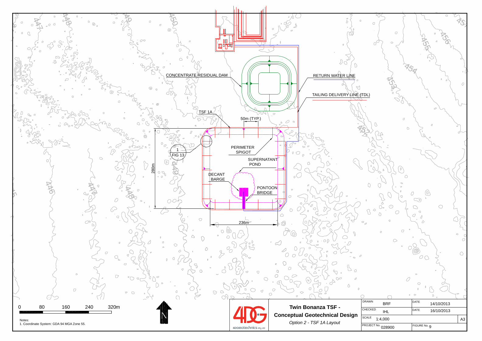
455
449
454
453
452
450449
448
456
457
448
447
446445
447446
FIG 13
DATE
DATE
FIGURE No.028900
BRF
9
DRAWN
A3
CHECKED
PROJECT No.
SCALE 1:4,000
IHL
Notes: 1. Coordinate System: GDA 94 MGA Zone 55.
0 80 160 240 320m
236m
280m
DECANT BARGE
PONTOONBRIDGE
PERIMETER SPIGOT
RETURN WATER LINE
TAILING DELIVERY LINE (TDL)
SUPERNATANT POND
1
CONCENTRATE RESIDUAL DAM
TSF 1A
14/10/2013
16/10/2013Twin Bonanza TSF -
Conceptual Geotechnical DesignOption 2 - TSF 1A Layout
50m (TYP.)
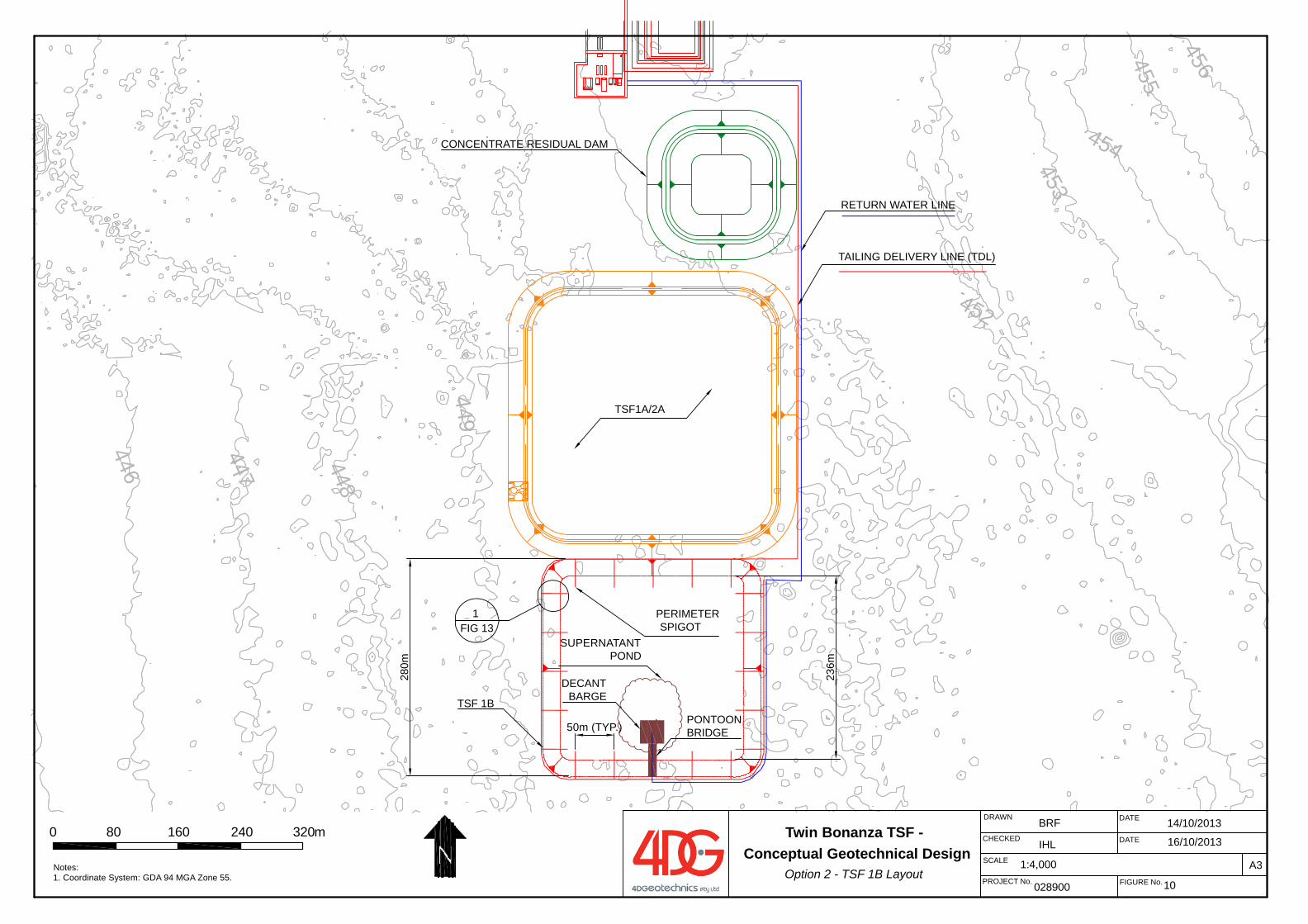
455454
453
452
449
448
456
447
4465
7
FIG 13
DATE
DATE
FIGURE No.028900
BRF
10
DRAWN
A3
CHECKED
PROJECT No.
SCALE 1:4,000
IHL
Notes: 1. Coordinate System: GDA 94 MGA Zone 55.
0 80 160 240 320m23
6m
280m
DECANT BARGE
PONTOONBRIDGE
PERIMETER SPIGOT
RETURN WATER LINE
TAILING DELIVERY LINE (TDL)
SUPERNATANT POND
1
TSF1A/2A
CONCENTRATE RESIDUAL DAM
TSF 1B
14/10/2013
16/10/2013Twin Bonanza TSF -
Conceptual Geotechnical DesignOption 2 - TSF 1B Layout
50m (TYP.)
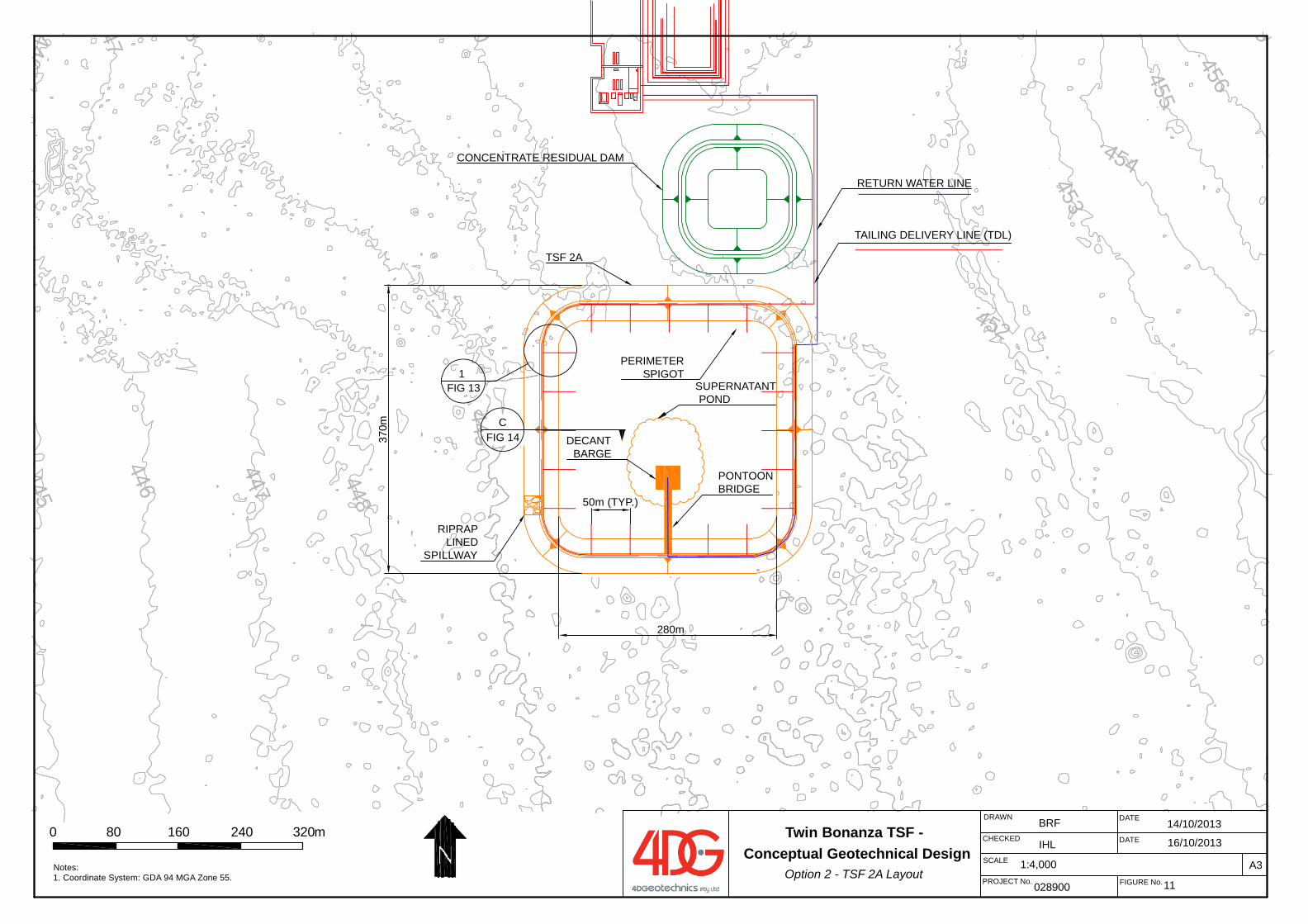
455454
453
452
0449
448
456
4578
447
446445
47446
DATE
DATE
FIGURE No.028900
BRF
11
DRAWN
A3
CHECKED
PROJECT No.
SCALE 1:4,000
IHL
Notes: 1. Coordinate System: GDA 94 MGA Zone 55.
0 80 160 240 320m
SUPERNATANT POND
370m C
FIG 14
RIPRAP LINED
SPILLWAY
DECANT BARGE
PONTOONBRIDGE
PERIMETER SPIGOT
RETURN WATER LINE
TAILING DELIVERY LINE (TDL)
1FIG 13
280m
CONCENTRATE RESIDUAL DAM
TSF 2A
14/10/2013
16/10/2013Twin Bonanza TSF -
Conceptual Geotechnical DesignOption 2 - TSF 2A Layout
50m (TYP.)
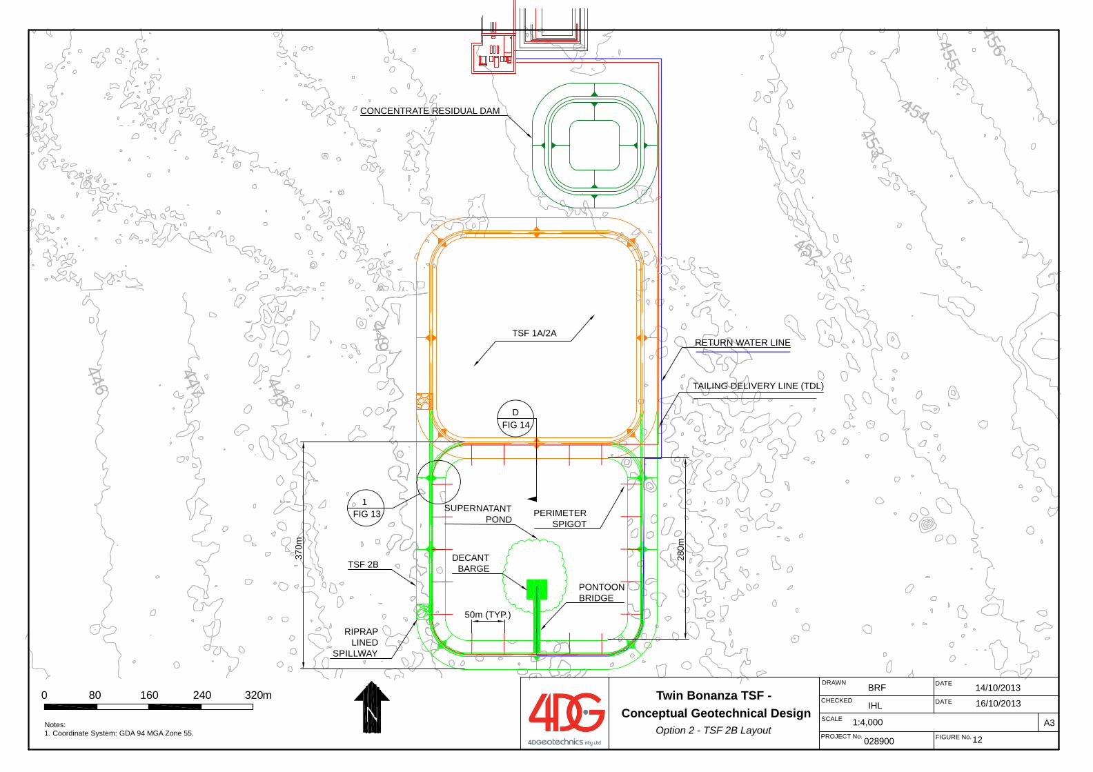
455
454
453452
449
448
456
447
446
FIG 13
DATE
DATE
FIGURE No.028900
BRF
12
DRAWN
A3
CHECKED
PROJECT No.
SCALE 1:4,000
IHL
Notes: 1. Coordinate System: GDA 94 MGA Zone 55.
0 80 160 240 320m
SUPERNATANT POND
370m
DFIG 14
RIPRAP LINED
SPILLWAY
DECANT BARGE
PONTOONBRIDGE
PERIMETER SPIGOT
RETURN WATER LINE
TAILING DELIVERY LINE (TDL)
1
280m
TSF 1A/2A
CONCENTRATE RESIDUAL DAM
TSF 2B
14/10/2013
16/10/2013Twin Bonanza TSF -
Conceptual Geotechnical DesignOption 2 - TSF 2B Layout
50m (TYP.)
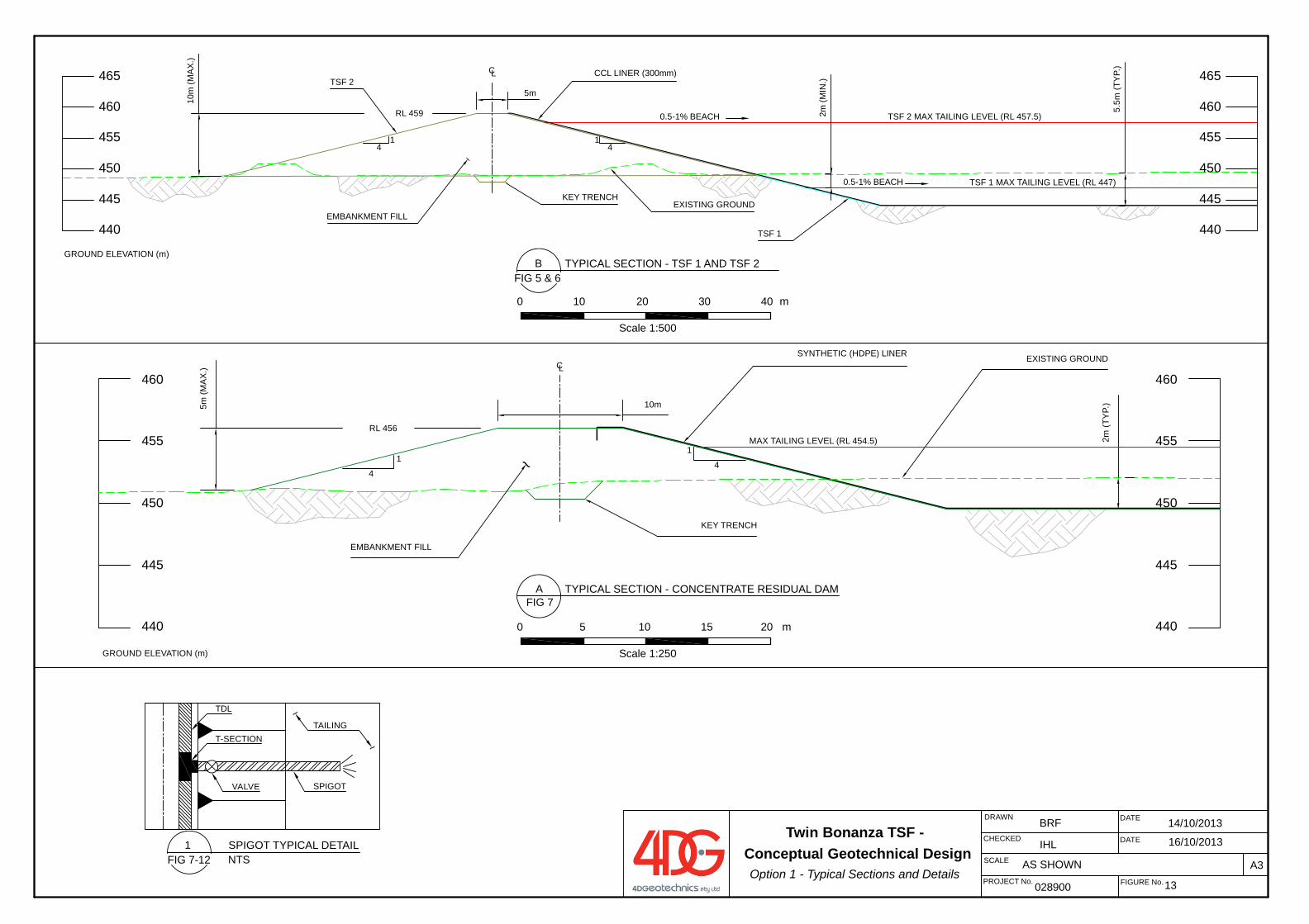
460
455
450
445
440
465
460
455
450
445
440
465
41
5m
RL 459
41
EXISTING GROUND
TSF 2 MAX TAILING LEVEL (RL 457.5)
TSF 1 MAX TAILING LEVEL (RL 447)
2m (M
IN.)
5.5m
(TY
P.)
EMBANKMENT FILL
~
TSF 2
TSF 1
CL CCL LINER (300mm)
0.5-1% BEACH
0.5-1% BEACH
GROUND ELEVATION (m)
KEY TRENCH10
m (M
AX
.)
460
455
450
445
440
CL
4
1
10m
SYNTHETIC (HDPE) LINER
RL 456
4
1
EXISTING GROUND
EMBANKMENT FILL
~
460
455
450
445
440
2m (T
YP.
)
GROUND ELEVATION (m)
MAX TAILING LEVEL (RL 454.5)
KEY TRENCH
5m (M
AX
.)
DATE
DATE
FIGURE No.028900
BRF 14/10/2013
13
DRAWN
A3
CHECKED
PROJECT No.
SCALE AS SHOWN
IHL 16/10/2013
BFIG 5 & 6
TYPICAL SECTION - TSF 1 AND TSF 2
0 10 20 30 40 m
AFIG 7
TYPICAL SECTION - CONCENTRATE RESIDUAL DAM
0 5 10 15 20 m
Scale 1:250
Scale 1:500
1 SPIGOT TYPICAL DETAILNTS
VALVE
TAILING~
~
TDL
T-SECTION
SPIGOT
FIG 7-12
Twin Bonanza TSF - Conceptual Geotechnical Design
Option 1 - Typical Sections and Details
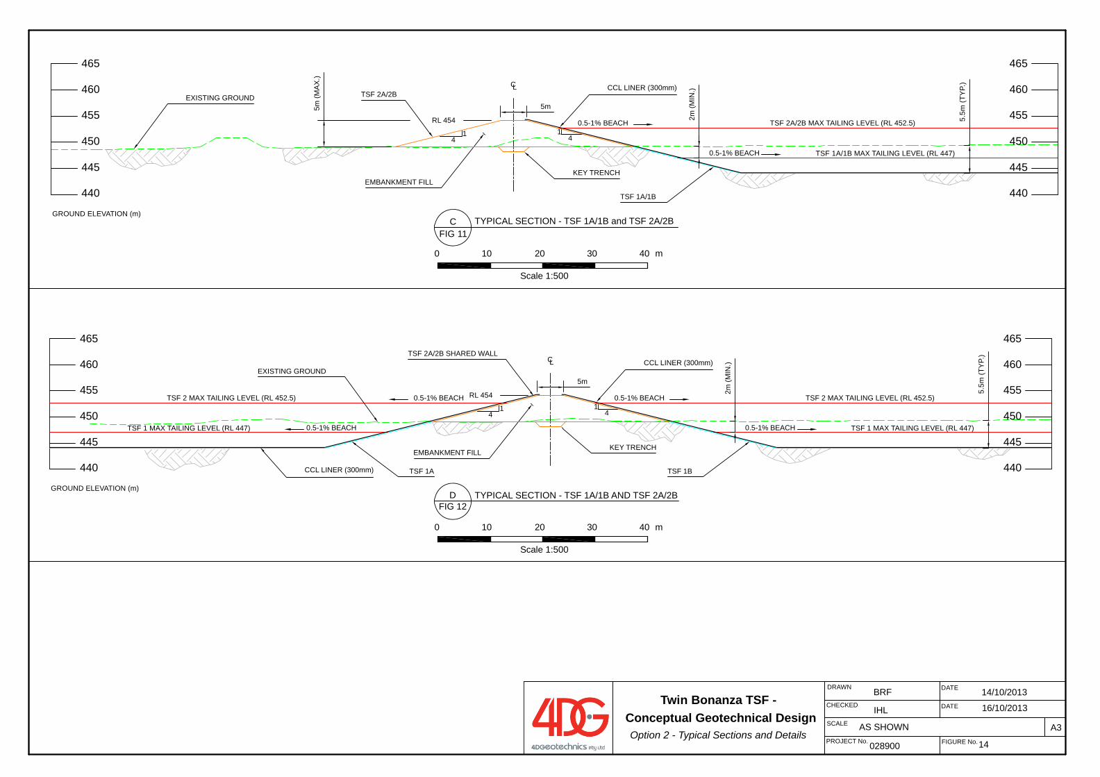
460
455
450
445
440
465
460
455
450
445
440
465
41
5m
41
TSF 2 MAX TAILING LEVEL (RL 452.5)
TSF 1 MAX TAILING LEVEL (RL 447)
2m (M
IN.)
5.5m
(TY
P.)
EMBANKMENT FILL
~
TSF 2A/2B SHARED WALL
TSF 1B
CL CCL LINER (300mm)
0.5-1% BEACH
0.5-1% BEACH
GROUND ELEVATION (m)
KEY TRENCH
TSF 2 MAX TAILING LEVEL (RL 452.5)
TSF 1 MAX TAILING LEVEL (RL 447)
0.5-1% BEACH
0.5-1% BEACH
TSF 1A
EXISTING GROUND
CCL LINER (300mm)
RL 454
460
455
450
445
440
465
460
455
450
445
440
465
41
5m
RL 454
41
EXISTING GROUND
TSF 2A/2B MAX TAILING LEVEL (RL 452.5)
TSF 1A/1B MAX TAILING LEVEL (RL 447)
2m (M
IN.)
5.5m
(TY
P.)
EMBANKMENT FILL
~
TSF 2A/2B
TSF 1A/1B
CL CCL LINER (300mm)
0.5-1% BEACH
0.5-1% BEACH
GROUND ELEVATION (m)
KEY TRENCH
5m (M
AX
.)
DATE
DATE
FIGURE No.028900
BRF
14
DRAWN
A3
CHECKED
PROJECT No.
SCALE AS SHOWN
IHL
CFIG 11
TYPICAL SECTION - TSF 1A/1B and TSF 2A/2B
0 10 20 30 40 m
DFIG 12
TYPICAL SECTION - TSF 1A/1B AND TSF 2A/2B
Scale 1:500
0 10 20 30 40 m
Scale 1:500
14/10/2013
16/10/2013Twin Bonanza TSF -
Conceptual Geotechnical DesignOption 2 - Typical Sections and Details
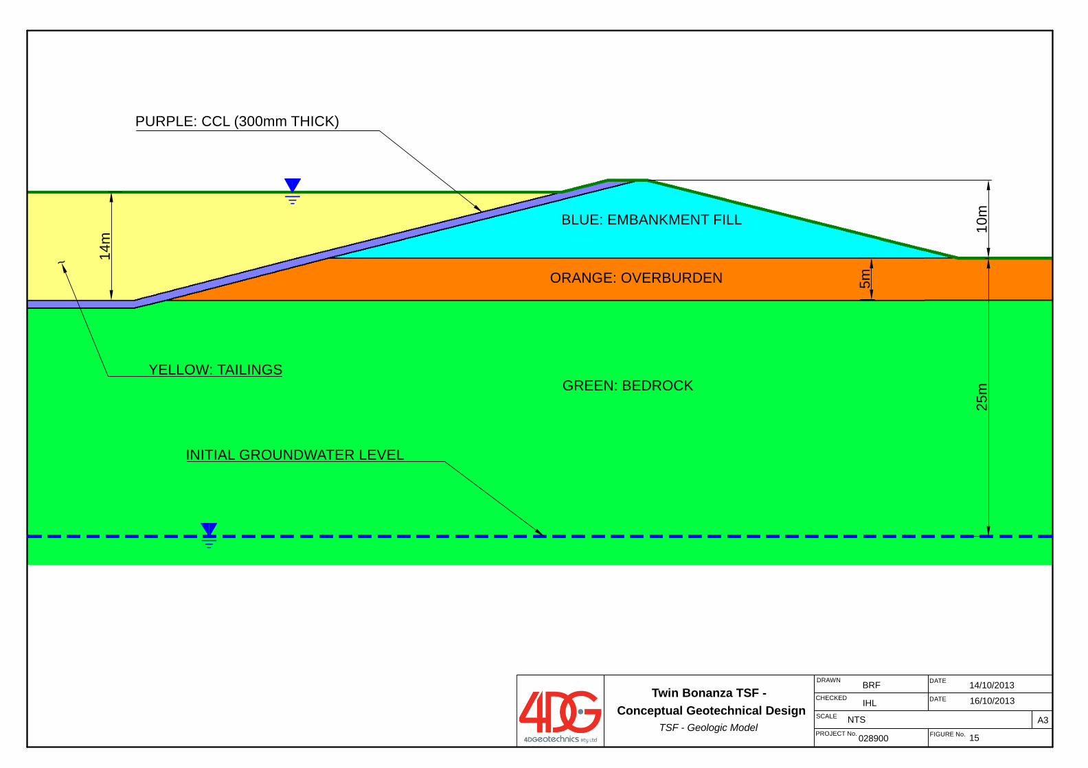
DATE
DATE
FIGURE No.028900
BRF 14/10/2013
15
DRAWN
A3
CHECKED
PROJECT No.
SCALE NTS
IHL 16/10/2013
25m
GREEN: BEDROCK
ORANGE: OVERBURDEN
BLUE: EMBANKMENT FILL 10m
PURPLE: CCL (300mm THICK)
5m
14m
YELLOW: TAILINGS
~
INITIAL GROUNDWATER LEVEL
Twin Bonanza TSF - Conceptual Geotechnical Design
TSF - Geologic Model
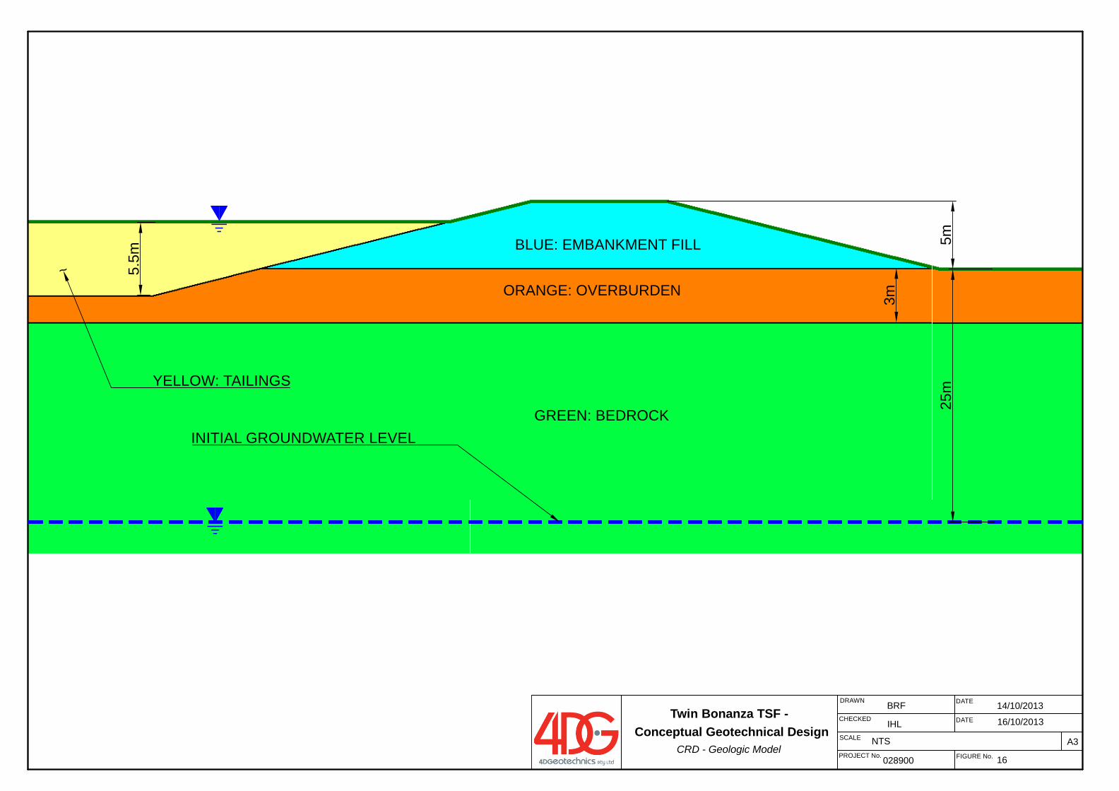
DATE
DATE
FIGURE No.028900
BRF
16
DRAWN
A3
CHECKED
PROJECT No.
SCALE NTS
IHL
25m
GREEN: BEDROCK
ORANGE: OVERBURDEN
BLUE: EMBANKMENT FILL 5m
3m
5.5m
YELLOW: TAILINGS
~
INITIAL GROUNDWATER LEVEL
Twin Bonanza TSF - Conceptual Geotechnical Design
CRD - Geologic Model
14/10/2013
16/10/2013
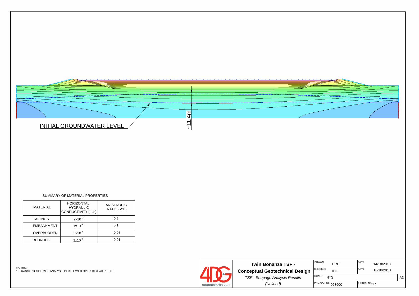
DATE
DATE
FIGURE No.028900
BRF
17
DRAWN
A3
CHECKED
PROJECT No.
SCALE NTS
IHLNOTES:1. TRANSIENT SEEPAGE ANALYSIS PERFORMED OVER 10 YEAR PERIOD.
SUMMARY OF MATERIAL PROPERTIES
MATERIALHORIZONTAL HYDRAULIC
CONDUCTIVITY (m/s)
ANISTROPIC RATIO (V:H)
TAILINGS 2x10 0.2-7
EMBANKMENT 1x10 0.1-6
OVERBURDEN 3x10 0.03-5
BEDROCK 1x10 0.01-5
INITIAL GROUNDWATER LEVEL ~11.
4m
Twin Bonanza TSF - Conceptual Geotechnical Design
TSF - Seepage Analysis Results (Unlined)
14/10/2013
16/10/2013
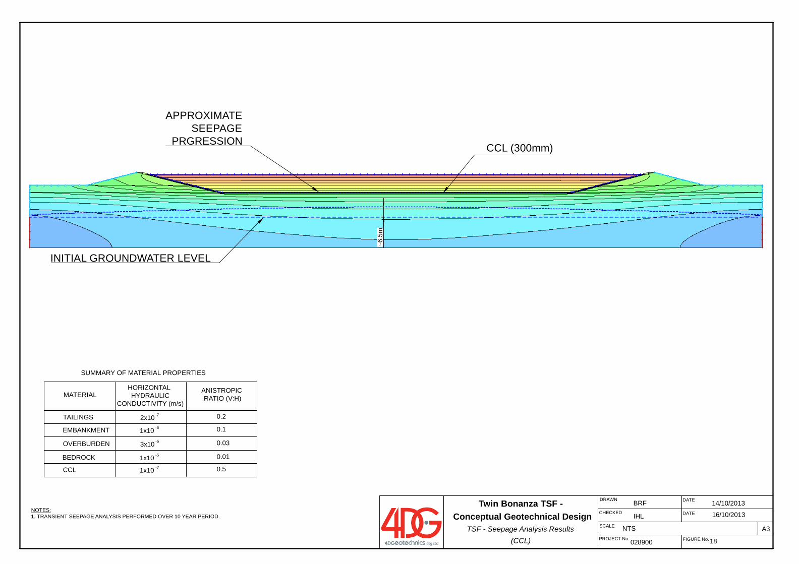
DATE
DATE
FIGURE No.028900
BRF
18
DRAWN
A3
CHECKED
PROJECT No.
SCALE NTS
IHLNOTES:1. TRANSIENT SEEPAGE ANALYSIS PERFORMED OVER 10 YEAR PERIOD.
SUMMARY OF MATERIAL PROPERTIES
MATERIALHORIZONTAL HYDRAULIC
CONDUCTIVITY (m/s)
ANISTROPIC RATIO (V:H)
TAILINGS 2x10 0.2-7
EMBANKMENT 1x10 0.1-6
OVERBURDEN 3x10 0.03-5
BEDROCK 1x10 0.01-5
CCL 1x10 0.5-7
CCL (300mm)
INITIAL GROUNDWATER LEVEL
APPROXIMATESEEPAGE
PRGRESSION
~6.5
m
Twin Bonanza TSF - Conceptual Geotechnical Design
TSF - Seepage Analysis Results (CCL)
14/10/2013
16/10/2013
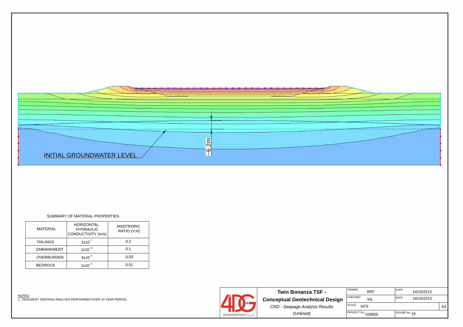
DATE
DATE
FIGURE No.028900
BRF
19
DRAWN
A3
CHECKED
PROJECT No.
SCALE NTS
IHLNOTES:1. TRANSIENT SEEPAGE ANALYSIS PERFORMED OVER 10 YEAR PERIOD.
SUMMARY OF MATERIAL PROPERTIES
MATERIALHORIZONTAL HYDRAULIC
CONDUCTIVITY (m/s)
ANISTROPIC RATIO (V:H)
TAILINGS 2x10 0.2-7
EMBANKMENT 1x10 0.1-6
OVERBURDEN 3x10 0.03-5
BEDROCK 1x10 0.01-5
INITIAL GROUNDWATER LEVEL ~6.2
m
Twin Bonanza TSF - Conceptual Geotechnical Design
CRD - Seepage Analysis Results (Unlined)
14/10/2013
16/10/2013
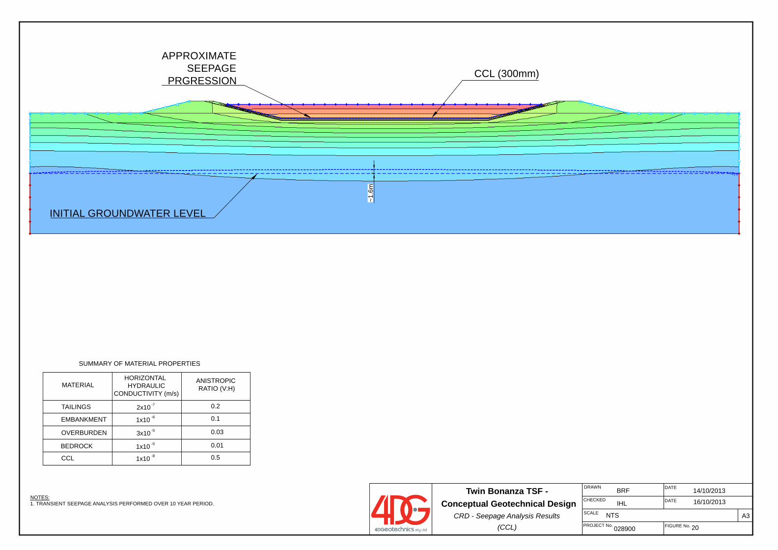
DATE
DATE
FIGURE No.028900
BRF
20
DRAWN
A3
CHECKED
PROJECT No.
SCALE NTS
IHLNOTES:1. TRANSIENT SEEPAGE ANALYSIS PERFORMED OVER 10 YEAR PERIOD.
SUMMARY OF MATERIAL PROPERTIES
MATERIALHORIZONTAL HYDRAULIC
CONDUCTIVITY (m/s)
ANISTROPIC RATIO (V:H)
TAILINGS 2x10 0.2-7
EMBANKMENT 1x10 0.1-6
OVERBURDEN 3x10 0.03-5
BEDROCK 1x10 0.01-5
CCL 1x10 0.5-8
CCL (300mm)
INITIAL GROUNDWATER LEVEL
APPROXIMATESEEPAGE
PRGRESSION
~1.6
m
Twin Bonanza TSF - Conceptual Geotechnical Design
CRD - Seepage Analysis Results (CCL)
14/10/2013
16/10/2013
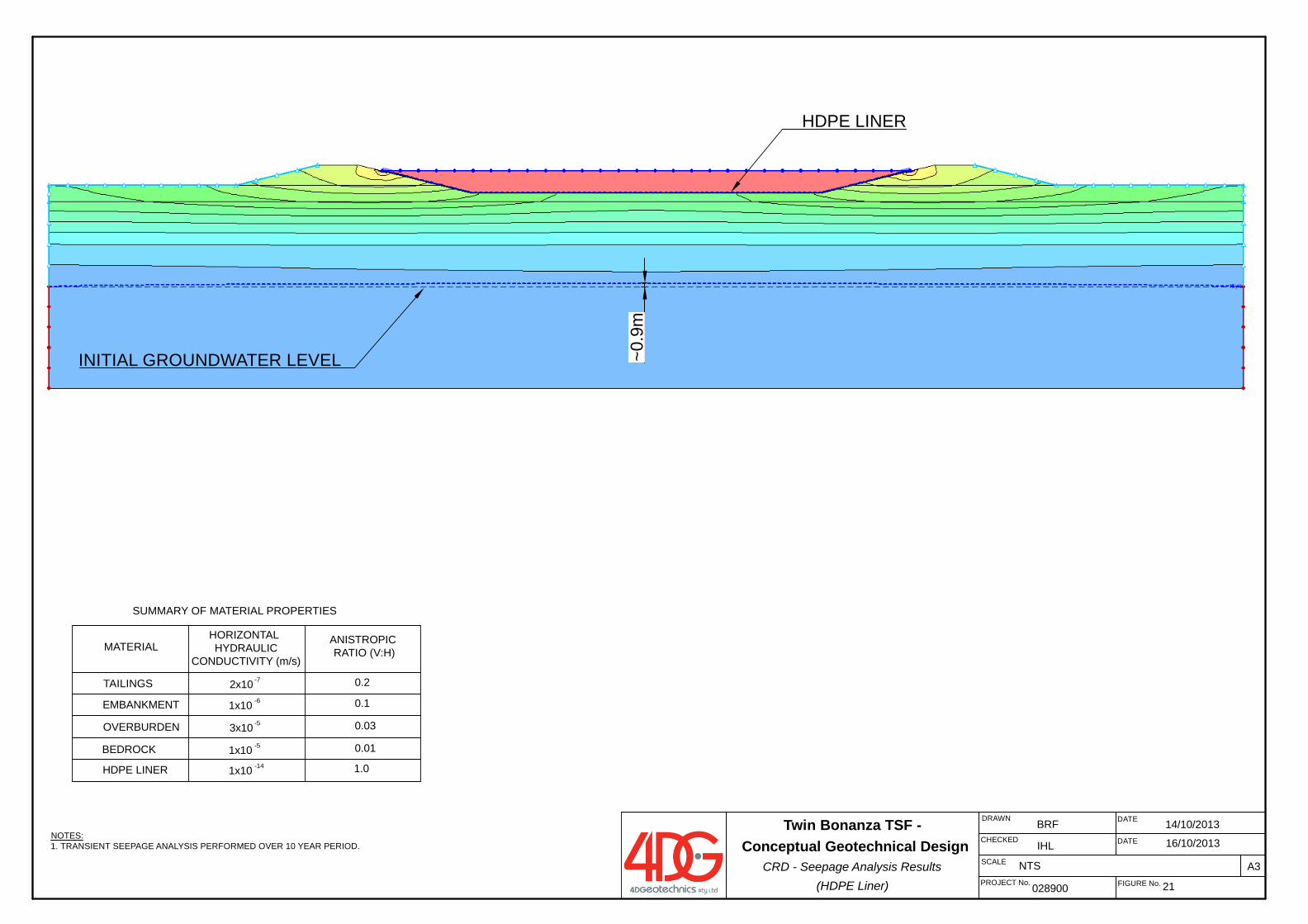
DATE
DATE
FIGURE No.028900
BRF
21
DRAWN
A3
CHECKED
PROJECT No.
SCALE NTS
IHL
~0.9
m
HDPE LINER
INITIAL GROUNDWATER LEVEL
NOTES:1. TRANSIENT SEEPAGE ANALYSIS PERFORMED OVER 10 YEAR PERIOD.
SUMMARY OF MATERIAL PROPERTIES
MATERIALHORIZONTAL HYDRAULIC
CONDUCTIVITY (m/s)
ANISTROPIC RATIO (V:H)
TAILINGS 2x10 0.2-7
EMBANKMENT 1x10 0.1-6
OVERBURDEN 3x10 0.03-5
BEDROCK 1x10 0.01-5
HDPE LINER 1x10 1.0-14
Twin Bonanza TSF - Conceptual Geotechnical Design
CRD - Seepage Analysis Results (HDPE Liner)
14/10/2013
16/10/2013
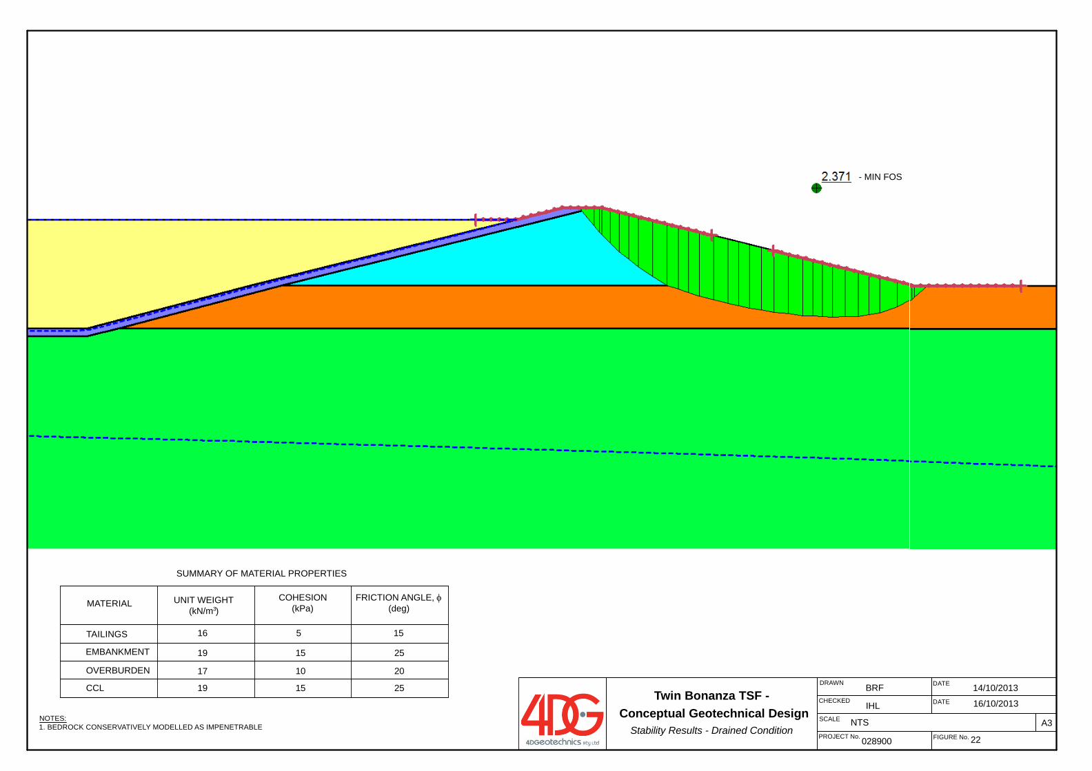
DATE
DATE
FIGURE No.028900
BRF
22
DRAWN
A3
CHECKED
PROJECT No.
SCALE NTS
IHL
1519
17
25
16 15
SUMMARY OF MATERIAL PROPERTIES
CCL
EMBANKMENT
5
3
OVERBURDEN 10
UNIT WEIGHT(kN/m )
MATERIAL COHESION (kPa)
1519
TAILINGS
20
25
NOTES:1. BEDROCK CONSERVATIVELY MODELLED AS IMPENETRABLE
FRICTION ANGLE, (deg)
- MIN FOS
Twin Bonanza TSF - Conceptual Geotechnical Design
Stability Results - Drained Condition
14/10/2013
16/10/2013
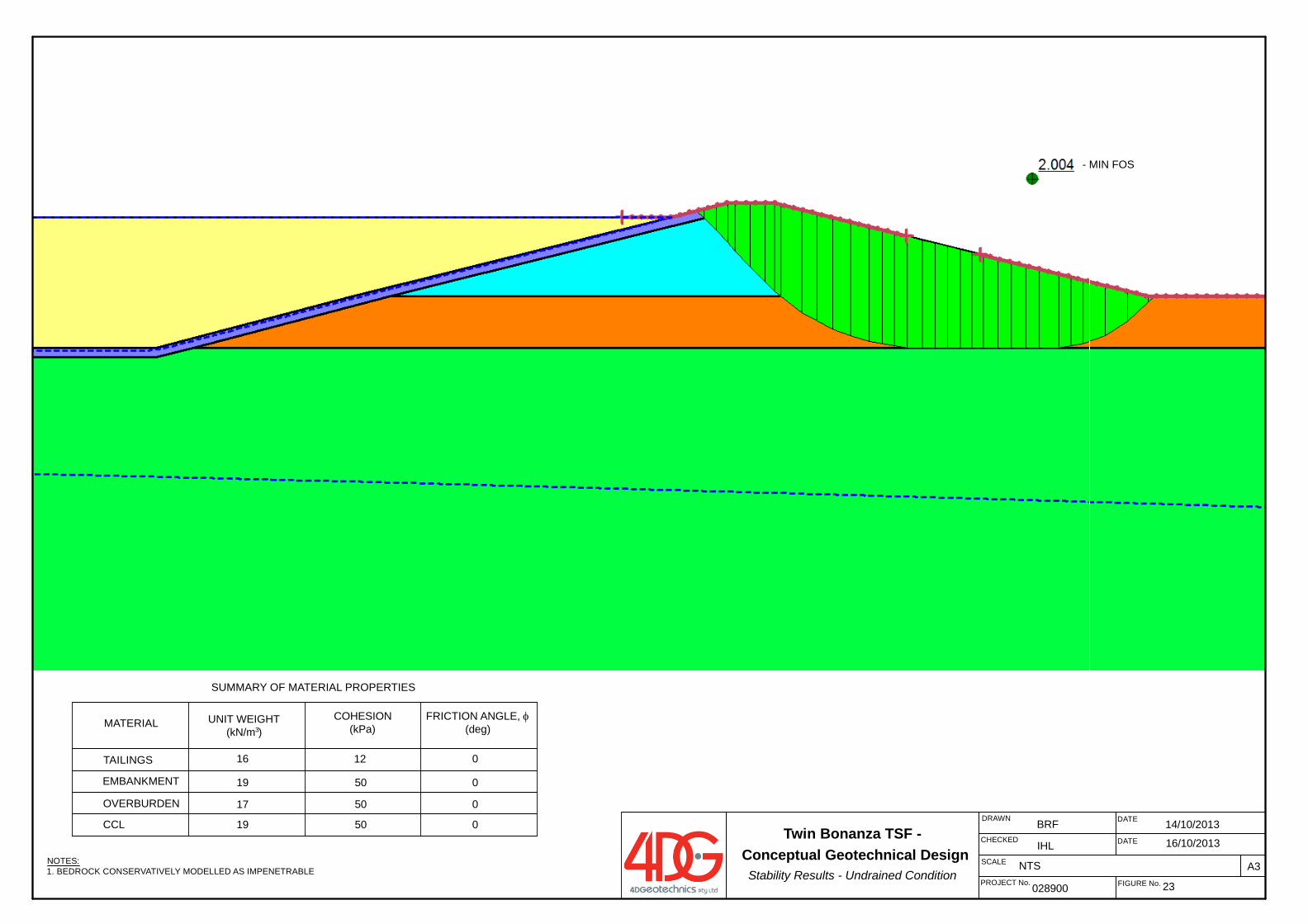
DATE
DATE
FIGURE No.028900
BRF
23
DRAWN
A3
CHECKED
PROJECT No.
SCALE NTS
IHL
5019
17
0
16 0
SUMMARY OF MATERIAL PROPERTIES
CCL
EMBANKMENT
12
3
OVERBURDEN 50
UNIT WEIGHT(kN/m )
MATERIAL COHESION (kPa)
5019
TAILINGS
0
0
NOTES:1. BEDROCK CONSERVATIVELY MODELLED AS IMPENETRABLE
FRICTION ANGLE, (deg)
- MIN FOS
Twin Bonanza TSF - Conceptual Geotechnical Design
Stability Results - Undrained Condition
14/10/2013
16/10/2013
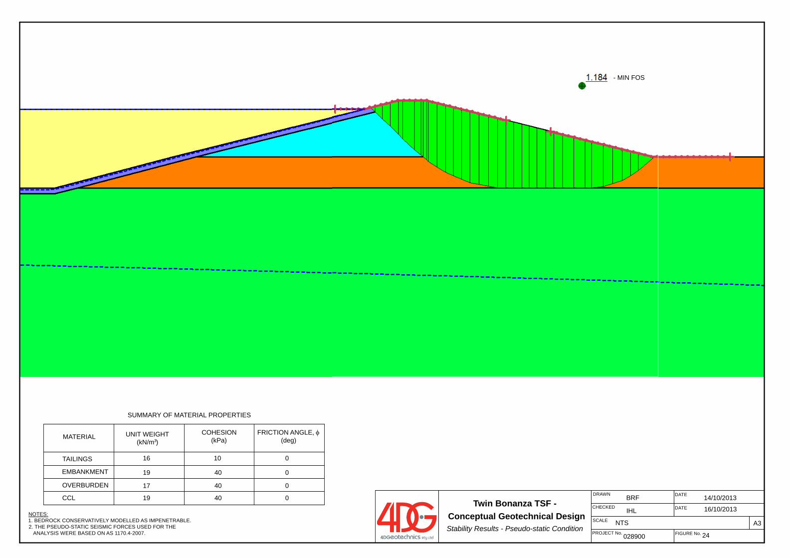
DATE
DATE
FIGURE No.028900
BRF
24
DRAWN
A3
CHECKED
PROJECT No.
SCALE NTS
IHL
4019
17
0
16 0
SUMMARY OF MATERIAL PROPERTIES
CCL
EMBANKMENT
10
3
OVERBURDEN 40
UNIT WEIGHT(kN/m )
MATERIAL COHESION (kPa)
4019
TAILINGS
0
0
NOTES:1. BEDROCK CONSERVATIVELY MODELLED AS IMPENETRABLE.2. THE PSEUDO-STATIC SEISMIC FORCES USED FOR THE ANALYSIS WERE BASED ON AS 1170.4-2007.
FRICTION ANGLE, (deg)
- MIN FOS
Twin Bonanza TSF - Conceptual Geotechnical DesignStability Results - Pseudo-static Condition
14/10/2013
16/10/2013
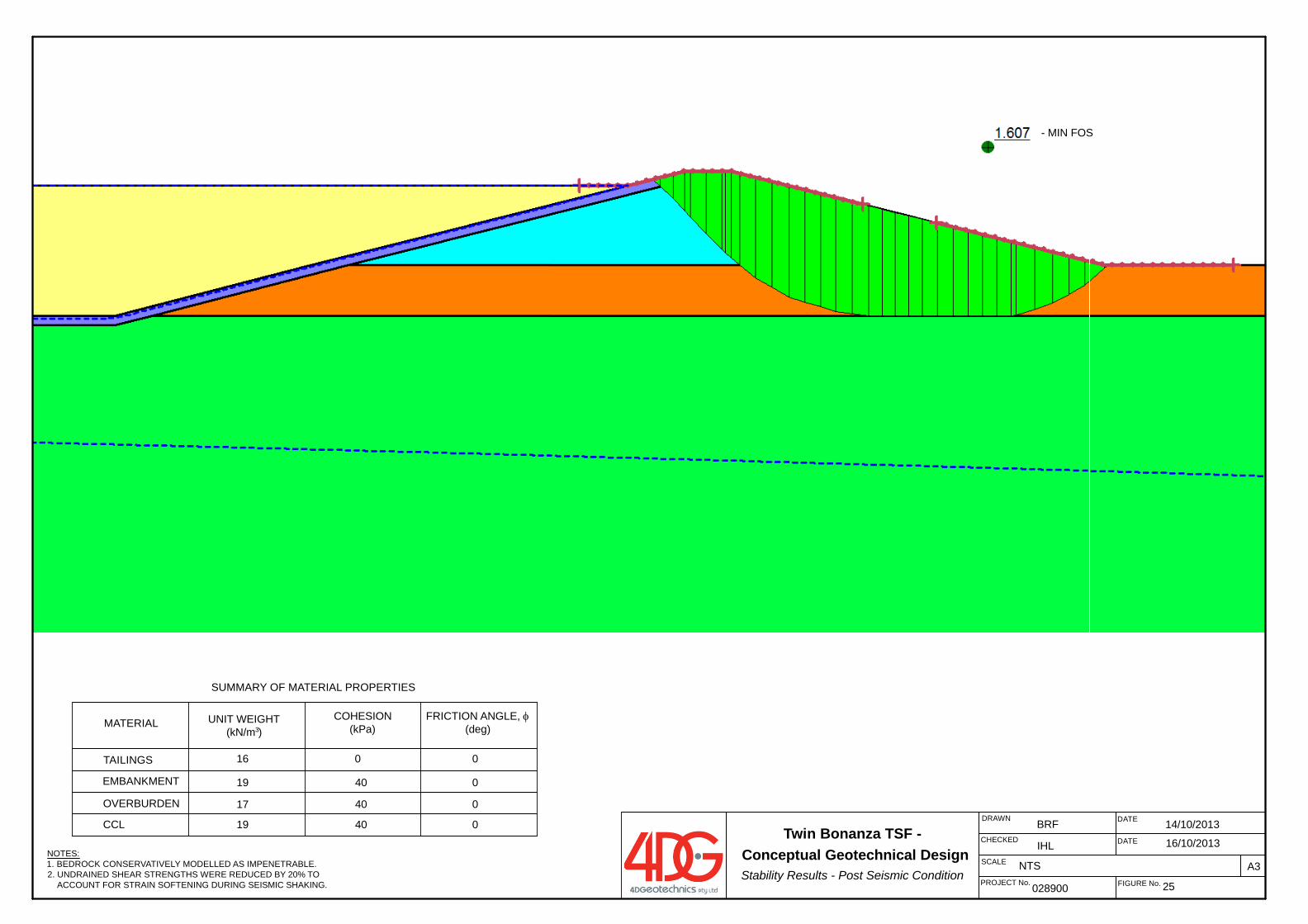
DATE
DATE
FIGURE No.028900
BRF
25
DRAWN
A3
CHECKED
PROJECT No.
SCALE NTS
IHL
SUMMARY OF MATERIAL PROPERTIES
MATERIAL UNIT WEIGHT(kN/m )
COHESION (kPa)
TAILINGS 0
3
EMBANKMENT
OVERBURDEN
CCL
FRICTION ANGLE, (deg)
16 0
04019
04017
04019
NOTES:1. BEDROCK CONSERVATIVELY MODELLED AS IMPENETRABLE.2. UNDRAINED SHEAR STRENGTHS WERE REDUCED BY 20% TO ACCOUNT FOR STRAIN SOFTENING DURING SEISMIC SHAKING.
- MIN FOS
Twin Bonanza TSF - Conceptual Geotechnical DesignStability Results - Post Seismic Condition
14/10/2013
16/10/2013

Ref: 028900REP01 Rev2
Commercial in Confidence
21 October 2013 APPENDIX A
APPENDIX A
ABM MEMORANDUM
MEMORANDUM Date: 16th August, 2013
Author: Pascal Hill
TO: Justin Robins
TITLE: Summary, TSF Geotechnical Data Review and Interpretations
1. INTRODUCTION
ABM Resources have made an application for a mineral lease to cover the Old Pirate deposit and smaller surrounding and associated deposits including Golden Hind and Old Glory. These deposits are collectively referred to Old Pirate and surrounds. The tenement application is referred to as Twin Bonanza and also contains the Buccaneer deposit. Ahead of proposed full-scale mining activities, ABM Resources are investigating design and location options for the construction of a long term Tailings Storage Facility proximal to the current trial processing area. Detailed data review and facility design will be completed by external parties. In preparation, data available to ABM has been compiled and reviewed. This memo gives a brief summary of existing data, and also describes interpretations that have been made from this data.
2. AVAILABLE DATA
2.1 HISTORIC MAPPING
Fact mapping was completed by North Flinders Mining geologists in 1994. No outcrop or subcrop is recorded in the Area of Interest; however it is unclear whether this reflects a lack of observed outcrop / subcrop or if the area was not included in the mapping campaign.
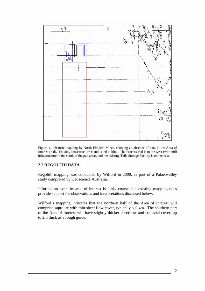
2
Figure 1. Historic mapping by North Flinders Mines, showing an absence of data in the Area of Interest (red). Existing Infrastructure is indicated in blue. The Process Pad is to the west (with mill infrastructure in the south of the pad area), and the existing Tails Storage Facility is on the east.
2.2 REGOLITH DATA
Regolith mapping was conducted by Wilford in 2000, as part of a Palaeovalley study completed by Geoscience Australia. Information over the area of interest is fairly coarse, but existing mapping does provide support for observations and interpretations discussed below. Wilford’s mapping indicates that the northern half of the Area of Interest will comprise saprolite with thin sheet flow cover, typically < 0.4m. The southern part of the Area of Interest will have slightly thicker sheetflow and colluvial cover, up to 2m thick as a rough guide.
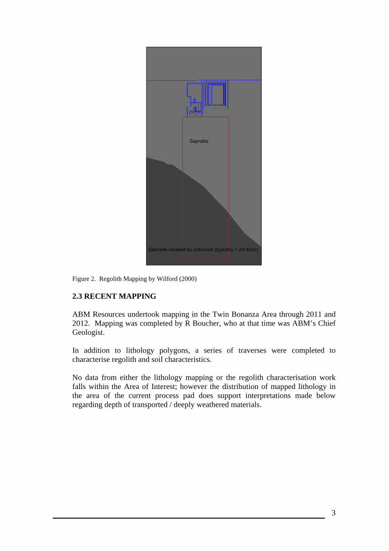
3
Figure 2. Regolith Mapping by Wilford (2000)
2.3 RECENT MAPPING ABM Resources undertook mapping in the Twin Bonanza Area through 2011 and 2012. Mapping was completed by R Boucher, who at that time was ABM’s Chief Geologist. In addition to lithology polygons, a series of traverses were completed to characterise regolith and soil characteristics. No data from either the lithology mapping or the regolith characterisation work falls within the Area of Interest; however the distribution of mapped lithology in the area of the current process pad does support interpretations made below regarding depth of transported / deeply weathered materials.
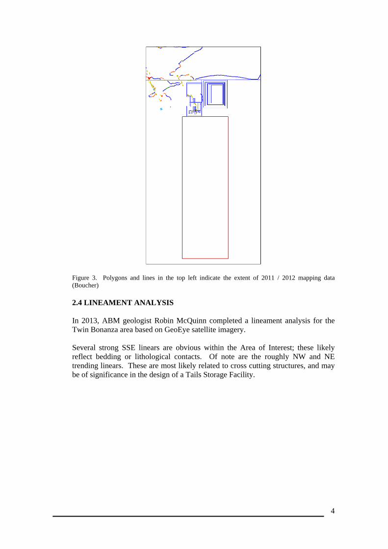
4
Figure 3. Polygons and lines in the top left indicate the extent of 2011 / 2012 mapping data (Boucher) 2.4 LINEAMENT ANALYSIS In 2013, ABM geologist Robin McQuinn completed a lineament analysis for the Twin Bonanza area based on GeoEye satellite imagery. Several strong SSE linears are obvious within the Area of Interest; these likely reflect bedding or lithological contacts. Of note are the roughly NW and NE trending linears. These are most likely related to cross cutting structures, and may be of significance in the design of a Tails Storage Facility.
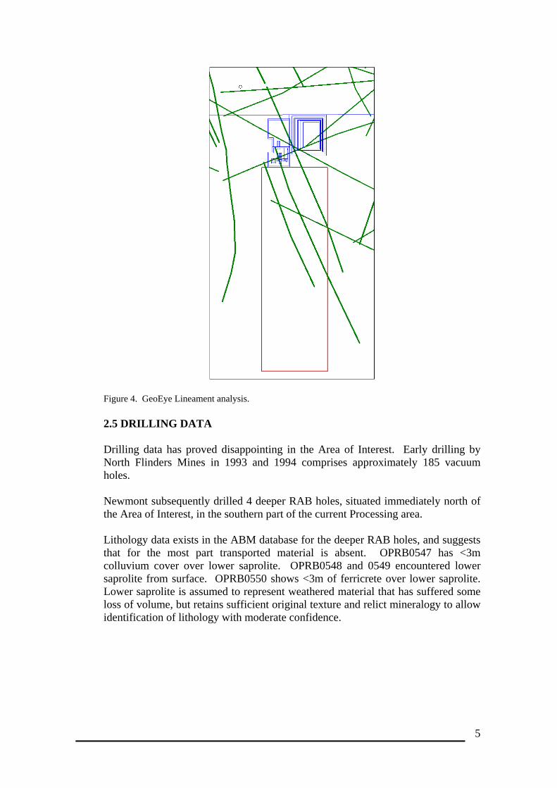
5
Figure 4. GeoEye Lineament analysis. 2.5 DRILLING DATA Drilling data has proved disappointing in the Area of Interest. Early drilling by North Flinders Mines in 1993 and 1994 comprises approximately 185 vacuum holes. Newmont subsequently drilled 4 deeper RAB holes, situated immediately north of the Area of Interest, in the southern part of the current Processing area. Lithology data exists in the ABM database for the deeper RAB holes, and suggests that for the most part transported material is absent. OPRB0547 has <3m colluvium cover over lower saprolite. OPRB0548 and 0549 encountered lower saprolite from surface. OPRB0550 shows <3m of ferricrete over lower saprolite. Lower saprolite is assumed to represent weathered material that has suffered some loss of volume, but retains sufficient original texture and relict mineralogy to allow identification of lithology with moderate confidence.
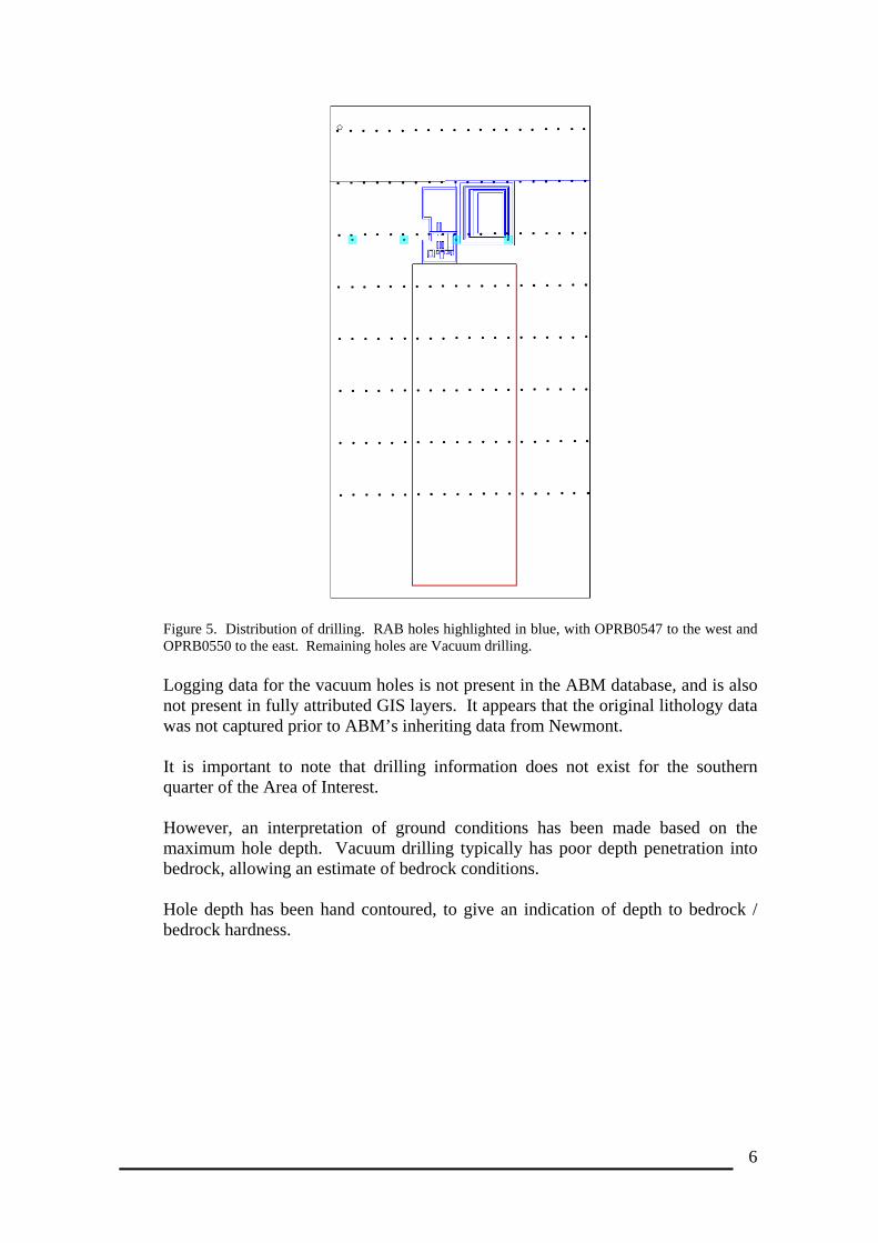
6
Figure 5. Distribution of drilling. RAB holes highlighted in blue, with OPRB0547 to the west and OPRB0550 to the east. Remaining holes are Vacuum drilling. Logging data for the vacuum holes is not present in the ABM database, and is also not present in fully attributed GIS layers. It appears that the original lithology data was not captured prior to ABM’s inheriting data from Newmont. It is important to note that drilling information does not exist for the southern quarter of the Area of Interest. However, an interpretation of ground conditions has been made based on the maximum hole depth. Vacuum drilling typically has poor depth penetration into bedrock, allowing an estimate of bedrock conditions. Hole depth has been hand contoured, to give an indication of depth to bedrock / bedrock hardness.
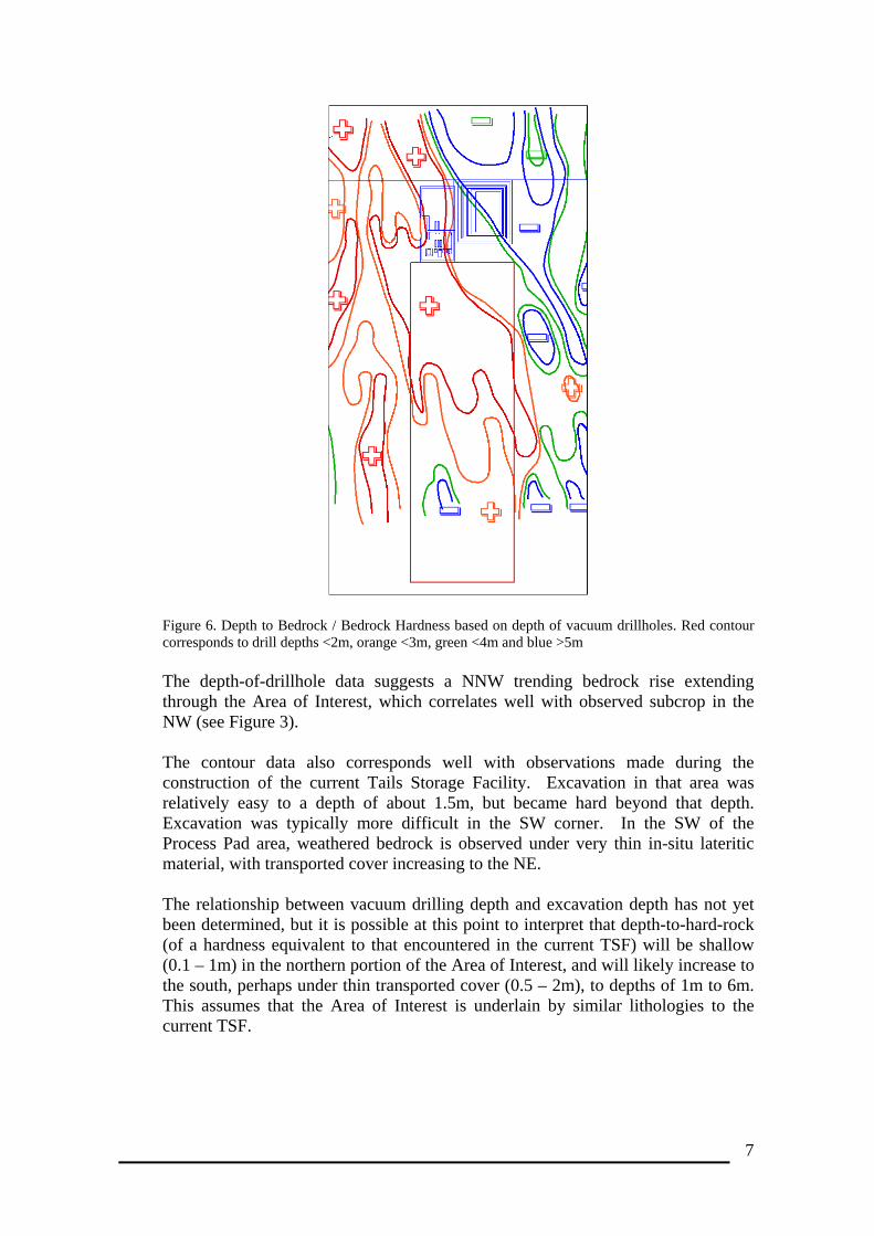
7
Figure 6. Depth to Bedrock / Bedrock Hardness based on depth of vacuum drillholes. Red contour corresponds to drill depths <2m, orange <3m, green <4m and blue >5m
The depth-of-drillhole data suggests a NNW trending bedrock rise extending through the Area of Interest, which correlates well with observed subcrop in the NW (see Figure 3). The contour data also corresponds well with observations made during the construction of the current Tails Storage Facility. Excavation in that area was relatively easy to a depth of about 1.5m, but became hard beyond that depth. Excavation was typically more difficult in the SW corner. In the SW of the Process Pad area, weathered bedrock is observed under very thin in-situ lateritic material, with transported cover increasing to the NE. The relationship between vacuum drilling depth and excavation depth has not yet been determined, but it is possible at this point to interpret that depth-to-hard-rock (of a hardness equivalent to that encountered in the current TSF) will be shallow (0.1 – 1m) in the northern portion of the Area of Interest, and will likely increase to the south, perhaps under thin transported cover (0.5 – 2m), to depths of 1m to 6m. This assumes that the Area of Interest is underlain by similar lithologies to the current TSF.

8
3. ADDITIONAL DATA REQUIREMENTS There may be additional lithology data within the database. The Database Administrator is currently out-of-the-office; however queries could be completed in the coming week. Geology evidence is apparently absent in the Area of Interest. It is unclear at this stage whether this reflects a lack of outcrop or a lack of recorded observations. Traversing of the area could prove beneficial, although there are limited resources available on site to conduct that work at short notice.