Embed Size (px)
Citation preview


RE PS 05-018-2015 Revision 1
Page 2 of 31
Contents
Introduction………………………………………………………………………………………….. 3
1 Scope………………………………….………………………………………………………....
2 Normative references …………………………………………………………………………
3 Terms and definition……..……………………………………………………………………...
4 Transportation, handling operations and storage…………………………………………
4.1 Transportation…….…………………….………………………………………….
4.2 Handling operations……………………………………………………………….
4.3 Stockholding and storage….………………………………….…………………..
5 Preparation of pipes for make-up………………….………………………………….........
5.1 General provisions…………………………………………………..…………….
5.2 Visual inspection ….………………………………………………….…..............
5.3 Thread protectors removal ….……………………………………………….
5.4 Thread connection inspection.………………………………………….…..……
5.5 Drifting ……….…………………………………………………………..….……...
5.6 Measurement of length of pipes …………………………………………………
5.7 Installation of thread protectors ………………………………………………….
6 Make-up of pipes ……………………………………………………………………………..
6.1 Running and Pulling ………………………………………………………………
6.2 Assembly of string …………………………………………………………………
6.3 Make-up inspection ……………………………………………………………….
6.4 Break-out of string …………………………………………………………………
7 Manufacturer’s warranty……………………………………………………………..………...
Attachment А Equipment for make-up registration …………………..………………………
Attachment B Types of damages and methods of repair……………………………………
Attachment C Thread compound application…………………………………………..……..
4
4
4
5
5
5
6
7
7
7
7
8
9
10
10
10
10
12
16
22
24
25
26
29
RE PS 05-018-2015 Revision 1
Page 3 of 31
Introduction
The present guidelines are worked out taking into account the requirements of the following
documents:
- API RP 5C1 Recommended Practice for Care and Use of Casing and Tubing;
- API RP 5В1 Gaging and Inspection of Casing, Tubing and Pipe Line Threads;
- ISO 10405 Petroleum and Natural Gas Industries – Care and Use of Casing and Tubing.
- TR CU 010/2011 – Technical Regulations of EAEC “on the Safety of Machinery and Equip-
ment”.
RE PS 05-018-2015 Revision 1
Page 4 of 31
Guidelines for use of casing with thread connection ТМК UP MAGNA
with GW compound
Effective date: June 30, 2016
1 Scope
The present guidelines contain recommendations for maintenance and use of casing with TMK
UP MAGNA with GW compound thread connection under field conditions, including pipe preparation
and make-up, string running and pulling operations, as well as guidelines for pipe handling, storage
and inspection during operation.
2 Normative references
The present guidelines refer to the following documents:
API RP 5A3/ISO 13678 Recommended Practice on Thread Compounds for Casing, Tubing,
and Line Pipe;
TU 0254-001-46977243-02 RUSMA-1 Thread Compound;
TU 0254-031-46977243-04 RUSMA R-4 Thread Compound’
TU 0254-068-46977243-2011 RUSMA Р-14 Thread Compound;
TU 0254-102-46977243-2011 RUSMA SP Thread Compound;
N O T E: The specified document revision shall be applied for dated references. The latest valid revision
shall be applied for undated references
3 Terms and definitions
For the purposes of these guidelines standard terms shall apply as well as the following terms
with the corresponding definitions:
3.1 rotation on shoulder: Excessive turns after shoulder to ensure thread connection
tightness.
3.2 pin (pin connection): A threaded connection on Oil Country Tubular Goods (OCTG) that
has external (male) threads and shoulder.
3.3 box (box connection): A threaded connection on Oil Country Tubular Goods (OCTG)
that has internal (female) threads and shoulder.
3.4 thread shoulders: Pin shoulder and box shoulder.
3.5 pin shoulder: Pin face, which serves as an arrester during make-up.

RE PS 05-018-2015 Revision 1
Page 5 of 31
3.6 box shoulder: Internal barrier, which serves as an arrester during make-up.
3.7 GW: Greenwell compound.
4 Transportation, handling operations and storage
4.1 Transportation
4.1.1 When pipes are transported by sea, railroad (railcars) or trucks, Cargo Shipping Rules and
Technical Provisions for Cargo Handling and Fastening applicable to the particular transport type shall be
observed.
4.1.2 Pipe transportation, handling and storage shall be carried out with thread protectors
screwed on pipe and coupling end-faces in order to protect thread surface, thread shoulders from
exposure.
4.1.3 Pipe bundles of different lots and standard sizes can be loaded into same means of
transportation, but have to be separated.
4.1.4 Pipe bundles shall be securely fastened during transportation to avoid any movement.
Wooden blocks can be used for fastening purposes.
When several pipes bundles are stacked or not bundled pipes are stacked into several ranks, pipe
bundles and pipe ranks shall be separated by at least three wooden blocks, with the thickness from
1,3780 – 1,5748 inch each, so that weight of upper pipe ranks is not distributed onto couplings of
lower ranks.
4.1.5 When transported by sea, pipe bundles shall not be placed in water inside the vessel’s
hold or in any other corrosive environment. Dragging of bundles along the piles or hitting bundles
against hatches or rails is strictly forbidden.
4.1.6 When loading pipe bundles into railway cars or trucks, wooden girders (blocks) shall be
provided for car floors or vehicle beds to ensure required distance between the products and uneven bottom
of the vehicle. No blocks shall be placed under couplings.
4.2 Handling operations
4.2.1 All handling operations with pipes shall be carried out with thread protectors screwed
on pipe and couplings ends.
4.2.2 Handling operations with pipe bundles shall be carried out only with the help of hoisting
transportation clamps.
In case of manual unloading, rope slings shall be used and pipes shall be rolled along guides in
parallel to the pile, avoiding quick movement and collision of pipe ends that might result in pipe and
coupling thread damage even with protectors in place.
When using the crane, spreader beams with slings shall be used according to approved slinging
diagrams.

RE PS 05-018-2015 Revision 1
Page 6 of 31
4.2.3 Pipes shall not be allowed to fall down from heights or be picked up by the upper pipe
end in a bundle with a hook or be dragged or subjected to any other actions that might damage pipe
and coupling threads, surfaces or shapes.
4.2.4 Handling operations with chromium steel pipes shall be performed using nylon or steel
harnesses with plastic braid. When using forklift, gripping forks, frames and clamps with
nonmetallic coating shall be employed.
4.2.5 Handling operations for chromium steel pipes shall exclude collision with hard bodies
having sharp edges that can result in sufficient local increase of pipe surfaces hardness and affect the
sulfide stress cracking resistance.
4.3 Stockholding and storage
4.3.1 Pipe storage conditions shall comply with GOST 15150 for Group 4 (storage period: 2
years). If storage of pipes is more than 2 years represervation shall be performed with the use of
preservative compound (like «Kendex OCTG» or equivalent) or preservative thread compound.
4.3.2 Pipes stockholding shall be performed in compliance with Materials, Equipment and
Spare Parts Stockholding and Storage Guidelines at production and technical maintenance facilities
ensuring their preservation and avoiding damage of pipe and coupling threads, surfaces or shapes.
4.3.3 Pipe bundles shall be stacked on supports spaced in a manner avoiding sagging or
thread damage. Rack supports shall be located in one plane and shall not sag under pile weight.
Rack bearing surface shall be minimum 11.8110 inch above the ground or floor.
Pipe bundles shall not be stocked on the ground, rails, steel or concrete floor!
It shall be no stones, sand, dirt on racks!
4.3.4 When several pipe bundles are stacked into a pile or not bundled pipes are stacked into
several ranks, pipe bundles and pipe ranks shall be separated by at least three wooden blocks, with
the thickness from 1.3780 – 1.5748 inch each, so that weight of upper pipe ranks is not distributed
onto couplings of lower ranks.
The height of the pipe pile shall not exceed 9.8425 ft.
4.3.5 Stockholding of unbundled pipes is allowed provided vertical posts are installed in the
racks.
4.3.6 If pipes are rolled on the racks, any movements at an angle to the rack axis shall be
excluded as that may result in collision of pipe ends and damage of thread or thread protectors.
4.3.7 During pipe storage availability and integrity of thread protectors, as well as compound
underneath and its expiration date shall be inspected. Pipe corrosion shall not be allowed.
4.3.8 Pipes damaged during transportation, rejected during inspection, prepared for repair or
awaiting a final decision shall be stored on separate racks with the corresponding tags.

RE PS 05-018-2015 Revision 1
Page 7 of 31
4.3.9 During chromium steel pipes storage, wood or plastic gaskets shall be placed onto all pipe
supports.
4.3.10 Drilling site shall have special area for pipe stockholding in compliance with above-listed re-
quirements.
4.3.11 Required quantity of racks shall be installed at drilling site in order to provide for stock-
holding of full set of pipes.
While stacking onto racks it is important to consider the order of string running (if it is specified
in the work instruction) to be sure that the first pipe according to the work plan is not under the pipes
that shall be run later. Pipes shall be placed onto racks in such a way as to ensure couplings are fac-
ing the wellhead.
5 Preparation of pipes for make-up
5.1 General provisions
Prior to lifting the pipes onto the rig site, proceed as follows:
- perform visual inspection of pipes and couplings;
remove thread protectors from pipes and couplings;
inspect pipe and coupling surfaces of thread connections
drift pipes along the entire length
measure the length of each pipe
re-install clean thread protectors on pipes and couplings
5.2 Visual inspection
Visual inspection of pipes, couplings and thread protectors shall be performed in order to detect
bent pipes, dents and damages.
Visual inspection of pipes and couplings shall be carried out with protectors screwed on.
Pipes, couplings, thread protectors with significant damages, discovered during visual inspec-
tion shall be put aside awaiting decision on their suitability for use.
Amount of damaged pipes shall be specified in the Product Quality Non-conformity Protocol and
all damaged areas shall be documented on photographs.
5.3 Thread protectors removal
Thread protectors shall be removed after thread connections are visually inspected.

RE PS 05-018-2015 Revision 1
Page 8 of 31
Thread protectors shall be removed manually or using a special tong with one person effort. In
case of difficulties when removing thread protectors heating of thread protectors with steam is allowed
or striking slightly with a wooden hammer at a protector`s end to eliminate a possible distortion.
5.4 Thread connection inspection
Thread connection shall be inspected by the following specialists:
- crews for casing strings assembly;
- companies specialized in casing inspection.
When running casing for the first time, representatives of the casing supplier shall be present.
Examples of thread connection exterior view with GW compound on pin and coupling are given
in Figures 1 and 2.
When inspecting pin and coupling connections, including thread surface, thread seals and
thread shoulders make sure you pay due attention to the following:
- mechanical damages availability;
- corrosion or other chemical damages caused as a result of environmental;
Under low light condition (twilight, night) individual portable light source shall be used during in-
spection.
Figure 1 – Pin

RE PS 05-018-2015 Revision 1
Page 9 of 31
Figure 2 - Coupling
5.5 Drifting
Pipe should be checked by drift along the entire length of the pipe. For pipes made of
chromium and corrosion-resistant steels polymer or aluminium drifts shall be used.
Before drifting, the pipe shall be positioned in such a manner as to avoid sagging. If any ropes
or bars are used for the drifting process, they shall be clean. In case of freezing temperatures, pipes
shall be heated prior to drifting, to remove snow and ice crust.
Pipe and drift shall be of the same temperature during drifting process.
Dimensions of the drift effective part shall comply with those specified in Table 1. Diameter of
the effective part of the drift shall be checked in three planes along the entire length after each 50
pipes check. If the diameter decreases by more than 0.0197 inch in any of the three planes, such a
drift shall be rejected.
The drift shall pass through the entire pipe, when pulled manually without significant effort.
If the drift cannot pass through the pipe, such a pipe shall be replaced with another pipe.
Pipes rejected during drifting process, shall be put aside until further decision on its validity.
Table 1 – Effective dimensions of the drift
Pipe outside diameter, inch Effective length of the drift inch Diameter of the effective part of the drift,
inch
14 - 20 12.0079 d – 0.1874
NOTES - d – is a nominal pipe inside diameter 1250 (1067)

RE PS 05-018-2015 Revision 1
Page 10 of 31
5.6 Measurement of length of pipes
Length of each pipe shall be measured from free (without a thread protector) coupling end to
free (without thread protector) pipe end.
It is recommended to compare measured pipe length with the marked length. In case of dis-
crepancies the measured length shall be marked on pipe body with a marker or chalk
When calculating the total length of the string, one should use the formula specified below:
L = ∑Lф – n ΔL (1)
where: L – the total length of the string;
∑Lф – overall length of pipes in a string, measured from pin end face to free coupling end face;
n – number of pipes in a string;
ΔL – decrease of length of pipes during make-up (see table 2).
Table 2 – Decreasing of pipe length during make-up process
Pipe outside diameter, inch Wall thickness, inch Decrease of pipe length during make-up
ΔL, inch
18 5/8 Up to 0.4921 4.2126
20 Up to 0.4921
4.2126
Above 0.4921 4.6535
5.7 Installation of thread protectors
Upon performance of inspection and control, thread protectors or caps shall be re-installed on
pipe and couplings ends.
Prior to installation thread protectors shall be thoroughly cleaned and shall not have considera-
ble damages, affecting protection of thread and thread seals from direct environmental impact.
6 Make-up of pipes
6.1 Running and Pulling
6.1.1 Casing shall be assembled by a qualified operator. To ensure declared operational
features of thread connection, make-up shall be performed with make-up torque registration system
applicable;
If make-up torque registration system is not available then the following shall be used in priority-
oriented order:
- manometer of breakout tong (conversion of pressure into torque in compliance with the tong
manufacturer recommendations);
- make-up triangle (cross stripe).
RE PS 05-018-2015 Revision 1
Page 11 of 31
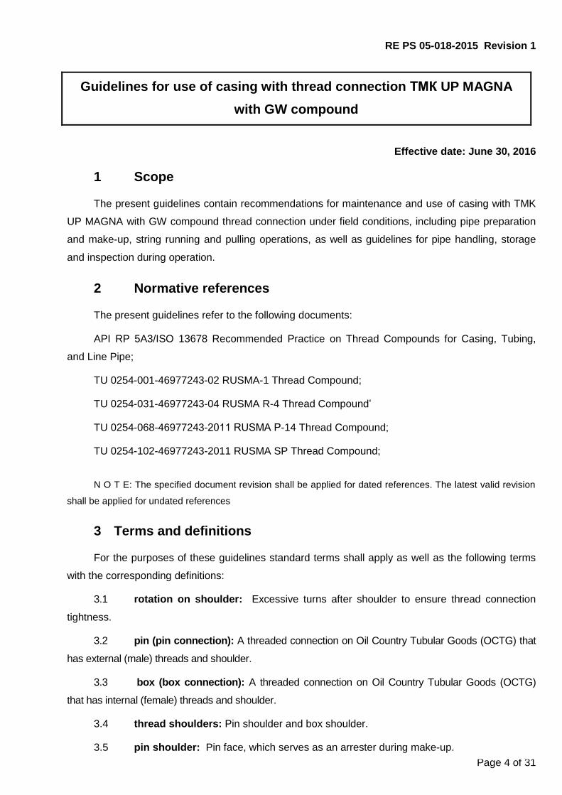
6.1.2 A special stab guide or bell guide is recommended for running and pulling operations
(Figure 3). The devices help to align pin and coupling and prevent the connection from damage.
6.1.3 In order to decrease probability of new damages during running and pulling operations,
it is recommended to use pipe weight balancer.
6.1.4 While running string of chrome steel pipes one should better use elevator or special
wedge claws to avoid pipe body damages.
Figure 3 – Make-up with special bell guide
6.1.5 Rotary tongs shall be equipped with a speed governor and ensure speed of 1 rpm at
the final stage of make-up.
Tongs shall be equipped with clamps for specific pipe sizes to ensure a larger contact area with
the pipe body. Clamp diameter shall be 1 % greater than pipe nominal diameter. Clamps shall be
adjusted in such a way that they hold the pipe tightly and never slip.
For make-up and break-out of chromium steel pipes, the rotary tongs shall be equipped with
non-metal or non-injurious tong dies.
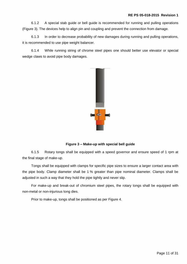
Prior to make-up, tongs shall be positioned as per Figure 4.
RE PS 05-018-2015 Revision 1
Page 12 of 31
Figure 4 –Rotary tongs positioning before make-up
6.1.6 Make-up equipment shall ensure torque at least 30% greater than recommended max-
imum make-up torque. Breaking-off requires higher torque than make-up.
6.2 Assembly of string
6.2.1 Make sure thread protectors are secured in place prior to lifting pipes on to the
rig floor.
Lifting pipes to the rig floor without thread protectors or end caps is not al-
lowed!
6.2.2 Prior to assembly of the string, remove thread protectors and check by touch surfaces
of thread shoulders of the free pipe end for any mechanical damage, check for alignment of the as-
sembled pipes (Figures 5 and 6).
6.2.3 Prior to make-up it is recommended to perform air blasting of pipe and coupling, make
sure that surfaces of thread, thread seals and thread shoulders with applied compound are free from
mud or mud laden fluid with small contaminations, hindering tightness of connection. In case of mud
or mud laden fluid on connection surfaces, you shall remove it from connection surfaces.
6.2.4 In case of combined assembly (one end of thread connection with GW compound is
made-up with the other end of thread connection without compound), thread compound shall be ap-
plied in accordance with Attachment B.

RE PS 05-018-2015 Revision 1
Page 13 of 31
Figure 5 – Mechanical damage inspection
Figure 6 – Alignment inspection
6.2.5 When stabbing pipe into coupling, pipe face end shall not hit coupling face end, pin
sliding down into the coupling end, when pipe face end contacts coupling face end is not allowed.
6.2.6 Make-up shall be performed with the torque specified in Table 3.
In case make-up of the connection with torque within the ranges, specified in Table 3 does not
comply with the settled requirements, Mopt can be corrected but maximum ±10 %. Herewith the values
of Mmin and Mmax shall also be corrected, but maximum ±10 % from the corrected Mopt .
6.2.7 During make up of pipes and couplings (or equipment) made of steels of different
grades, the make-up torque value shall be chosen according to the least grade of pin or coupling.
6.2.8 When making-up chromium steels pipes, the first two turns shall be carried out
manually, or a strap tong can be used (Figure 10). Chain tong is allowed for use only under condition
that the pipe body is secured from damage (e.g. safe gasket which is set between the pipe body and
the tong).

RE PS 05-018-2015 Revision 1
Page 14 of 31
Figure 7 – Make-up start with strap tongs
6.2.9 Make-up rotation speed during connection make-up with the rotary tong shall corre-
spond to the values specified in Table 4.
Таble 4 – Rotation speed during make-up
Start of make-up End of make-up
(rotation on shoulder) First two revolutions Further revolutions
Speed maximum 2 rpm
Better manually
Speed more than 2 rpm,
but not more than 10 rpm
Speed maximum
2 rpm
6.2.10 Even longitudinal movement of the pipe resulting from gradual increase of number of
engaged revolutions, shall be watched, significant warming of the connection (not more than 500 С of
the ambient temperature) shall not be allowed.
.

RE PS 05-018-2015 Revision 1
Page 15 of 31
Table 5 – Make-up torques
D, inch
S, inch
Torque, ft. lb. for steel grades
J55, K55 N80, L80 R95, С95,T95 С110, Р110 Q125 TMK140 TMK150
Мmin Мopt Мmax Мmin Мopt Мmax Мmin Мopt Мmax Мmin Мopt Мmax Мmin Мopt Мmax Мmin Мopt Мmax Мmin Мopt Мmax
18 5/8 0.4350 30800 34100 37500 30800 34100 37500 30800 34100 37500 30800 34100 37500 30800 34100 37500 30800 34100 37500 30800 34100 37500
0.4850 34200 38100 41800 34200 38100 41800 34200 38100 41800 34200 38100 41800 34200 38100 41800 34200 38100 41800 34200 38100 41800
20
0.4382 30900 34300 37700 30900 34300 37700 30900 34300 37700 30900 34300 37700 30900 34300 37700 30900 34300 37700 30900 34300 37700
0.5000 34400 38200 42000 34400 38200 42000 34400 38200 42000 34400 38200 42000 34400 38200 42000 34400 38200 42000 34400 38200 42000
0.6350 40000 44400 48800 40000 44400 48800 40000 44400 48800 40000 44400 48800 40000 44400 48800 40000 44400 48800 40000 44400 48800
RE PS 05-018-2015 Revision 1
Page 16 of 31
6.2.11 Make-up shall not cause significant mechanical damages like galling or jamming etc.
on the pipe and coupling body.
The outer surface of coupling shall be free of damages with depth larger than 0.5% from the
coupling nominal outside diameter.
Damages from tong clamps are allowed on the pipe outer surface under condition that the
actual pipe wall thickness taking into account depth of the damage shall be not less than 87.5%
from the nominal pipe wall thickness.
Upon make-up of chromium steel pipes the trace depth on the pipe body shall be not more
than 0.0079 inch.
6.2.12 The final connection make-up torque shall be within the range from Мmin to Мmax.
6.2.13 When the maximum value of the final make-up torque (Мmax) is achieved, turning of
coupling from the side of mill connection is allowed, if the diagram is not changed during correct
make-up (figure 10). The final make-up torque values shall be within Мmin to Мopt limits in order to
reduce the probability of turning.
6.3 Make-up inspection
6.3.1 Make-up inspection by the make-up diagram.
6.3.1.1 If the make-up is performed correctly and all the thread connection geometric param-
eters comply with the requirements of the regulatory documentation, the make-up diagram will
show defined areas, which correspond to torque increase due to thread surfaces mating (area I),
and the further mating and thread shoulders (area II), as shown in the Figure 11 below.
The rotary torque increase on the first revolutions corresponding to the initial mating of
thread surfaces shall be smooth and even. Further on, with mating of the thread surfaces and of
thread shoulders, acceleration of rotary torque increase till shouldering of the connection shall take
place, which confirms that make-up is performed correctly.
Depending on the rotary tong used, and its adjustment, the make-up diagram (especially
area I) can show areas with insignificant deviation from straight line: waves, leaps, etc. Such
deviations shall be deemed acceptable if general view of the make-up diagram corresponds to the
established requirements.

RE PS 05-018-2015 Revision 1
Page 17 of 31
Figure 11 – Correct make-up diagram
6.3.1.2 The make-up diagrams for the pipes from the same lot shall be close in shape.
6.3.1.3 Shoulder torque Мsh of thread shoulders (box shoulder and pin shoulder) shall be
within the range from 5 % and 80 % of optimum make-up torque Мopt.
6.3.1.4 Final make-up torque shall be within the range from minimum to maximum make-
up torque.
6.3.1.5 Typical discrepancies of make-up diagram are specified in Figures 12 – 17.
6.3.1.6 If at the final step of make-up procedure torque increase stops and there appears
a horizontal area (area II, Figure 12), but no slippage of clamp jaws is observed and the area IV
length is maximum 0.12 of revolution, then such a make-up shall be considered acceptable. If not,
the connection shall be broken-out, inspected for absence of damages and deformations. If during
inspection of thread and thread shoulders no surface damages or shape distortions, such as de-
crease of pin or box shoulder inside diameter, sagging on the coupling inside surface, are ob-
served, re-assembly of the connection can be performed.

RE PS 05-018-2015 Revision 1
Page 18 of 31
Figure 12 – Make-up diagram. Torque increase stopped in the area III
6.3.1.7 Too low value of shoulder torque Мsh of thread shoulders on make-up diagram (Fig-
ure 13) may result from:
- Unfavorable combination of technologic parameters of the connection;
- Application of wrong type of compound;
- Compound contamination or its poor storage conditions.
Break out the connection, clean off the compound and inspect it. If the visual inspection is
satisfactory, reapply compound of the proper type and quality and make-up the connection again.
Figure 13 – Make-up diagram. Low value shoulder torque of thread shoulders
6.3.1.8 Too high value of shoulder torque Мsh on make-up curve (Figure 14) may result
from:
- damage of thread;

RE PS 05-018-2015 Revision 1
Page 19 of 31
- improper thread cleaning;
- application of wrong type of compound;
- thread compound contamination;
- high density of thread compound (e.g. at low temperatures);
- unfavorable combination of technologic parameters of the connection.
Break out the connection, clean off the thread compound, and inspect it. If the visual inspec-
tion is satisfactory, reapply thread compound of the proper type and quality, and make-up again.
If the shape of the make-up diagram after re-make-up is not changed, the pipe shall be laid
aside and make-up with another pipe shall be performed. The pipe that was laid aside is allowed to
be used for further make-ups if no surface damages or thread and thread shoulders shape distor-
tions are observed. If the shape of the make-up diagram, when being made-up with another pipe,
is not changed, the connection shall be broken-out and the previous pipe shall be replaced.
Figure 14 – Make-up diagram. High value shoulder torque of thread shoulders
6.3.1.9 Torque leaps on the make-up diagram (Figure 15) can be caused by:
- uneven application of thread compound and improper cleaning from preservative com-
pound;
- rotary tongs jam;
- uneven torque of rotation on shoulder.
Break out the connection, clean it off the compound, and inspect it. If the visual inspection is
satisfactory, reapply thread compound of the appropriate type and quality, check the tong setting
and repeat make-up.
If the shape of the make-up diagram after remake-up is not changed, laid aside the pipe and
perform make-up with another pipe. The laid aside pipe is allowed to be used for further make-up if
no damages or damages that can be repaired are observed (Table 2). After the damages are re-

RE PS 05-018-2015 Revision 1
Page 20 of 31
paired, reapply the thread compound of the appropriate type and quality, check the settings of
equipment and repeat make-up.
If the shape of the make-up diagram when being made-up with another pipe is not changed,
break out the connection and replace the previous pipe.
Figure 15 – Make-up diagram Torque leaps
6.3.1.11 Make-up curve without clear shoulder torque Мsh (Figure 16) can result from:
- thread damage;
- improper thread cleaning;
- unfavorable combination of technologic parameters of the connection.
Break out the connection, clean it off the compound, and inspect it. If the visual inspection is
satisfactory, reapply thread compound of the appropriate type and quality and repeat make-up.
If the shape of the make-up diagram after remake-up is not changed, lay aside the pipe and
perform make-up with another pipe. The laid aside pipe is allowed to be used for further make-up if
no surface damages or thread and thread shoulders shape distortions are observed.
If the shape of the make-up diagram when being made-up with another pipe is not changed
break out the connection and replace the previous pipe.
RE PS 05-018-2015 Revision 1
Page 21 of 31
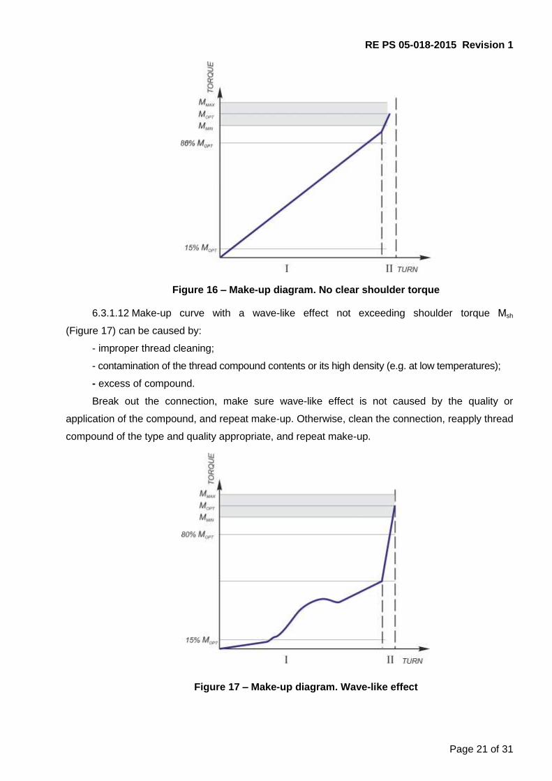
Figure 16 – Make-up diagram. No clear shoulder torque
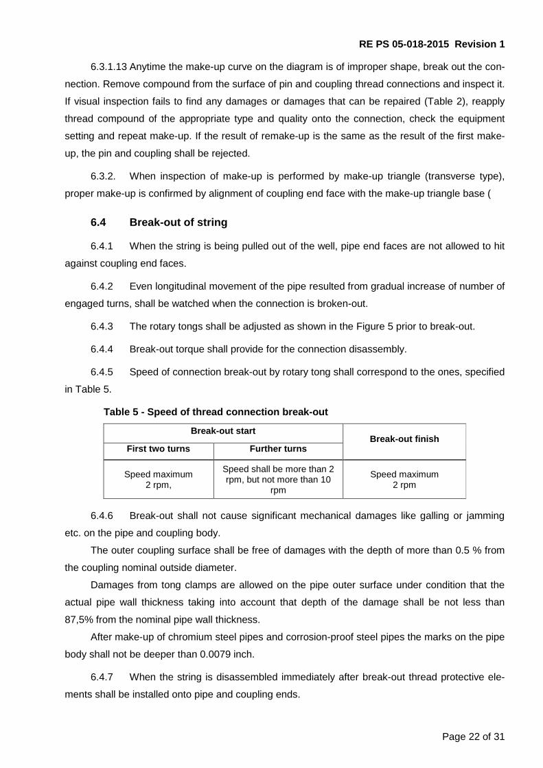
6.3.1.12 Make-up curve with a wave-like effect not exceeding shoulder torque Мsh
(Figure 17) can be caused by:
- improper thread cleaning;
- contamination of the thread compound contents or its high density (e.g. at low temperatures);
- excess of compound.
Break out the connection, make sure wave-like effect is not caused by the quality or
application of the compound, and repeat make-up. Otherwise, clean the connection, reapply thread
compound of the type and quality appropriate, and repeat make-up.
Figure 17 – Make-up diagram. Wave-like effect
RE PS 05-018-2015 Revision 1
Page 22 of 31
6.3.1.13 Anytime the make-up curve on the diagram is of improper shape, break out the con-
nection. Remove compound from the surface of pin and coupling thread connections and inspect it.
If visual inspection fails to find any damages or damages that can be repaired (Table 2), reapply
thread compound of the appropriate type and quality onto the connection, check the equipment
setting and repeat make-up. If the result of remake-up is the same as the result of the first make-
up, the pin and coupling shall be rejected.
6.3.2. When inspection of make-up is performed by make-up triangle (transverse type),
proper make-up is confirmed by alignment of coupling end face with the make-up triangle base (
6.4 Break-out of string
6.4.1 When the string is being pulled out of the well, pipe end faces are not allowed to hit
against coupling end faces.
6.4.2 Even longitudinal movement of the pipe resulted from gradual increase of number of
engaged turns, shall be watched when the connection is broken-out.
6.4.3 The rotary tongs shall be adjusted as shown in the Figure 5 prior to break-out.
6.4.4 Break-out torque shall provide for the connection disassembly.
6.4.5 Speed of connection break-out by rotary tong shall correspond to the ones, specified
in Table 5.
Table 5 - Speed of thread connection break-out
Break-out start Break-out finish
First two turns Further turns
Speed maximum 2 rpm,
Speed shall be more than 2 rpm, but not more than 10
rpm
Speed maximum 2 rpm
6.4.6 Break-out shall not cause significant mechanical damages like galling or jamming
etc. on the pipe and coupling body.
The outer coupling surface shall be free of damages with the depth of more than 0.5 % from
the coupling nominal outside diameter.
Damages from tong clamps are allowed on the pipe outer surface under condition that the
actual pipe wall thickness taking into account that depth of the damage shall be not less than
87,5% from the nominal pipe wall thickness.
After make-up of chromium steel pipes and corrosion-proof steel pipes the marks on the pipe
body shall not be deeper than 0.0079 inch.
6.4.7 When the string is disassembled immediately after break-out thread protective ele-
ments shall be installed onto pipe and coupling ends.

RE PS 05-018-2015 Revision 1
Page 23 of 31
6.4.8 To store used pipes after string disassembly, if necessary, following preparations
shall be carried out:
- visual inspection of thread protectors for damages (See 5.2);
- visual inspection of pipes and couplings for significant mechanical damages (like galling,
jamming etc.) (See 5.2);
- cleaning of pipes and couplings thread connections from compound and contaminations
(See 5.4);
- visual inspection of thread, thread seals and thread shoulders surfaces of pins and coupling
(See 5.5). In case of any damages detection, repair as per Table 1 or reject the pipes and cou-
plings;
- cleaning of thread protectors from previous compound and contaminations (See 5.8);
- application of preservation compound (like «Kendex OCTG» or equivalent) or
preservative thread compound onto pipe and coupling thread connections and installation of thread
protectors according to Cl. 5.8.
6.4.9 In case of any damages detection, repair as per Attachment B or reject the pipes
and couplings;
6.4.10 Delamination of GW compound form the pin or coupling thread surface with the size
of not more than 20% from the covered surface with the possibility of further application is allowed.
The examples of thread connection exterior view with GW compound of pin and coupling upon
break-out of string are specified in Figures 18 and 19.
Figure 18 – Pin
RE PS 05-018-2015 Revision 1
Page 24 of 31
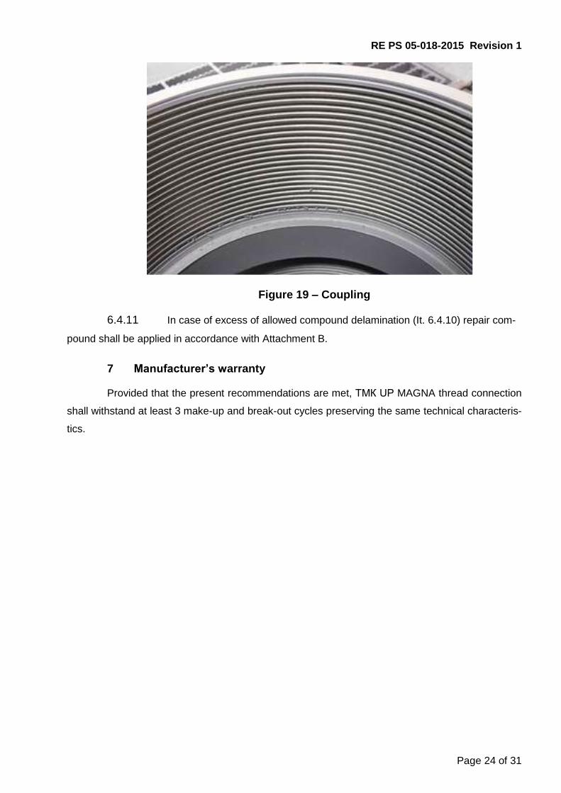
Figure 19 – Coupling
6.4.11 In case of excess of allowed compound delamination (It. 6.4.10) repair com-
pound shall be applied in accordance with Attachment B.
7 Manufacturer’s warranty
Provided that the present recommendations are met, ТМК UP MAGNA thread connection
shall withstand at least 3 make-up and break-out cycles preserving the same technical characteris-
tics.
RE PS 05-018-2015 Revision 1
Page 25 of 31
Attachment А
(mandatory)
Equipment for make-up registration
ТМК UP MAGNA thread connection shall be made-up using equipment for make-up registra-
tion and saving of make-up diagram (make-up curve) in a graphical or electronic format.
The curve is plotted based on torque values along vertical axis and number of turns along
horizontal axis which shall have a linear scale. Only two last revolutions shall be displayed as
torque increases at end of make-up.
When using a computer make-up diagram shall have the following characteristics:
- Sufficient resolution (at least 800 × 600 pixels) for precise curve display. Display shall be at
least 9.8425 inch in diagonal, herewith make-up curve shall take at least 80 % of display;
- Display of minimum and maximum torque with horizontal lines (if required, optimum torque
shall be displayed).
- Display of minimum and maximum shoulder torque of thread shoulders with horizontal
lines.
- Automatic and manual determination of shoulder torque of thread shoulders.
- Display of rig floor number of each make-up.
- Display of date and time of each make-up.
- Availability of comments.
- Display of company-customer name, well number, pipe diameter, weight, steel grade, type
of thread connection, thread compound data and pipe manufacturer.
- When applicable, superimposing of latest make-up curve over the curves of previous
satisfactory make-up diagrams;
- When applicable, display of make-up speed in rpm, either on the make-up curve or on a
separate graph.
Displayed make-up results shall not be sufficient for acceptance or rejection of make-up op-
erations. Correctness of make-up shall be confirmed by a competent specialist.
Prior to running the casing downhole, the calibration certificate with the latest and
next planned equipment calibration dates shall be checked!

RE PS 05-018-2015 Revision 1
Page 26 of 31
Attachment B
(mandatory)
B1 Possible damages that might occur on areas of thread surfaces, thread seals,
thread shoulders of pipe and coupling thread connections before putting into operation and the
ways of their removal are listed in Table B 1.
If any unacceptable damages are detected on pipes, such pipes shall be rejected then
and reported accordingly specifying pipes serial numbers, describing defects found with photos
attached.
Table B 1 – Types of damages and methods of repair
Surface Area (Figure B 1)
Type of damage Damage Repair
1, 2, 4, 6
Pit corrosion less than 0.0039 inch deep or insignificant surface rust
Manual repair (removal) using non-metal brush with soft bristle or corrosion converter or polish-ing paper with grain 0
Pit corrosion more than 0.0039 inch deep
Not to be repaired, shall be rejected
Burrs less than 0.0118 inch wide. Tears and scratches less than 0.0039 inch deep
Manual repair using needle file or polishing paper with grain 0
Dents, nicks and other mechanical dam-ages
Not to be repaired, shall be rejected
3, 5
Pit corrosion less than 0.0118 inch deep or insignificant surface rust
Manual repair using needle file or polishing paper or non-metal brush with soft bristle or corrosion converter
Pit corrosion more than 0.0118 inch deep
Not to be repaired, shall be rejected
Burrs less than 0.0118 inch wide. Tears and scratches less than 0.0118 inch deep
Manual repair using needle file or polishing paper with grain 0
B2 Determination of corrosion depth, scratches, tears, burrs height shall be performed
upon removal of GW compound in the area of defect:
- a mould made of a detected defect using special tape (material “X Coarse” of Testex
company for defects up to 0.0039 inch deep, for deeper defects: X-Coarse Plus or equivalent).
Mould height shall be measured with a thickness gage, measurement accuracy shall be at least
0.0004 inch (PEACOCK G2-127 or equivalent).
RE PS 05-018-2015 Revision 1
Page 27 of 31
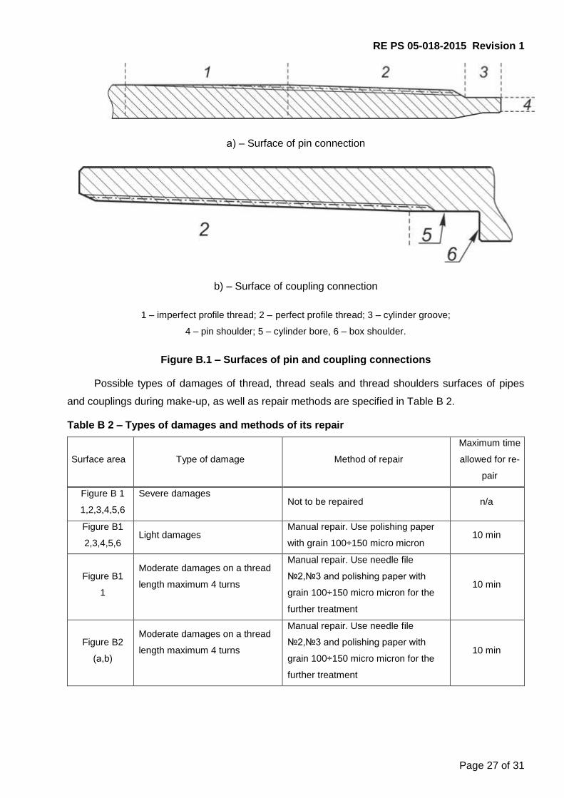
а) – Surface of pin connection
b) – Surface of coupling connection
1 – imperfect profile thread; 2 – perfect profile thread; 3 – cylinder groove;
4 – pin shoulder; 5 – cylinder bore, 6 – box shoulder.
Figure B.1 – Surfaces of pin and coupling connections
Possible types of damages of thread, thread seals and thread shoulders surfaces of pipes
and couplings during make-up, as well as repair methods are specified in Table B 2.
Table B 2 – Types of damages and methods of its repair
Surface area Type of damage Method of repair
Maximum time
allowed for re-
pair
Figure B 1
1,2,3,4,5,6
Severe damages
Not to be repaired n/a
Figure B1
2,3,4,5,6 Light damages
Manual repair. Use polishing paper
with grain 100÷150 micro micron 10 min
Figure B1
1
Moderate damages on a thread
length maximum 4 turns
Manual repair. Use needle file
№2,№3 and polishing paper with
grain 100÷150 micro micron for the
further treatment
10 min
Figure B2
(а,b)
Moderate damages on a thread
length maximum 4 turns
Manual repair. Use needle file
№2,№3 and polishing paper with
grain 100÷150 micro micron for the
further treatment
10 min

RE PS 05-018-2015 Revision 1
Page 28 of 31
а) – Pin thread connection surface
b) coupling thread connection surface
Figure B 2 – Surface areas of pin and coupling connections
B.4 If upon repair or break-out surface coating damages are more than 20% of the area
of pin and coupling with GW compound, damaged areas shall be covered with “RUSMA Polimer
Premium P” repair compound applied with a brush in a uniform layer. Holding time shall be 3-5
minutes.
B.5 If damages are not more than 20% of the area of pin and coupling with GW com-
pound, coating repair is not required. The required properties of the compound are provided with
the remaining compound area.
If repair compound is not available further use of pipes shall be carried out only using the
recommended thread compound in accordance with Attachment B.
RE PS 05-018-2015 Revision 1
Page 29 of 31
Attachment C
(Recommended)
Thread compound application
C.1 To ensure optimum conditions for make-up and to avoid burrs of mating surfaces, all
surfaces of thread, thread seals and thread shoulders of pins and couplinges shall be provided with
thread compound. Thread compound shall comply with API RP 5A3/ISO 13678.
The following thread compounds are recommended:
- RUSMA-1 as per TU 0254-001-46977243-02
- RUSMA-R-4 as per TU 0254-031-46977243-04
- RUSMA-SP as per TU 0254-102-46977243
While make-up of chromium steel pipes RUSMA-14 compound shall be used as per
TU0254-068-46977243.
Upon coordination with the connection designer, other than mentioned thread compounds
can be applied; provided they comply with RP 5A3/ISO 13678 requirements and provide for thread
connection sealability, as well as for protection from galling and corrosion.
C.2 Thread compound for make-up shall only be taken from original packages, delivered
by the supplier, the container shall show name, batch number and manufacturing date.
Compound from packages without proper identification shall never be used.
Compound shall never be placed in other packages or thinned!
Compound applied shall be even, of ointment consistency, free from any solid inclusions
(stones, sand, dry compound, fine chips, etc.).
Prior to use, check compound’s expiration date on the package. Never apply compound
with expired shelf life.
Make sure you follow the recommendations specified below when using thread
compound:
- use the same compound (the same type) when assembling one casing string;
- use a new compound package for each running, if the compound from opened package
is used, make sure it is free from foreign inclusions;
- stir the compound thoroughly before use;
- warm up compound before application in case of freezing temperatures.
Compound shall be stored in closed overturned packages at the temperature specified by
the manufacturer. When storing partially unused compound always specify the date of the first use
on the package.

RE PS 05-018-2015 Revision 1
Page 30 of 31
C.3 Thread compound shall be applied with an even layer on all thread surface, thread
seals and thread shoulders of pins and couplings connections. Figures C1 and C2 demonstrate
proper and improper application of compound.
Compound shall be applied only to thoroughly cleaned and dried surfaces of thread con-
nection.
Never use metal brushes for compound application!
Figure C.1 – Proper and Improper application of thread compound
Figure C.2 – Proper distribution of thread compound over thread profile

RE PS 05-018-2015 Revision 1
Page 31 of 31
C.4 Required amount of thread compound shall be distributed between coupling and pin
ends as follows: two thirds shall be at the coupling and one third shall be at the pin.
Minimum and maximum compound amount, mmin and mmax, in grams, required for make-up
one connection, shall be calculated as follows:
mmin = 0.014 х D (C.1)
mmax = 0.017 х D (C.2)
where: mmin – minimum compound amount, lb, rounded to the nearest whole number;
mmax – maximum compound amount, lb, rounded to the nearest whole number;
D – nominal outside diameter, inch, rounded to the nearest whole number.
Example - Minimum thread compound required for make-up of one threaded
connection of pipes with nominal diameter of 20.0000 inch:
Mmin = 0.014 х 20.0000 = 0.280 lb
Here with, at least 0,19 lb shall be applied on coupling end and at least 0,09 lb – on pin.
To determine the quantity of compound required for determined number of pipes, a package
of compound with specified volume shall be used.
Prior to pipes running down the hole, make sure that required thread compound is available.
C.5 Thread sealant can be used for make-up pipes with crossovers or other string
elements provided the below conditions are followed:
- shoulder torque of thread shoulders is within the limits of minimum and maximum make-up
torque;
- shoulder torque of thread shoulders is from 70 % to 80 % of optimum make-up torque, and
the torque of rotation on shoulder is higher than optimum torque;
- shoulder torque of thread shoulders is higher than 80 % of optimum make-up torque and it
does not result from thread jamming or damage, and 20 % of optimum make-up torque is applied
after the shoulders interlock.