Embed Size (px)
Citation preview

March 28, 2017
Melanie A. Bachman
Acting Executive Director
Connecticut Siting Council
10 Franklin Square
New Britain, CT 06051
RE: Notice of Exempt Modification for T-Mobile / L700 Crown Site BU: 876325
T-Mobile Site ID: CT11062B
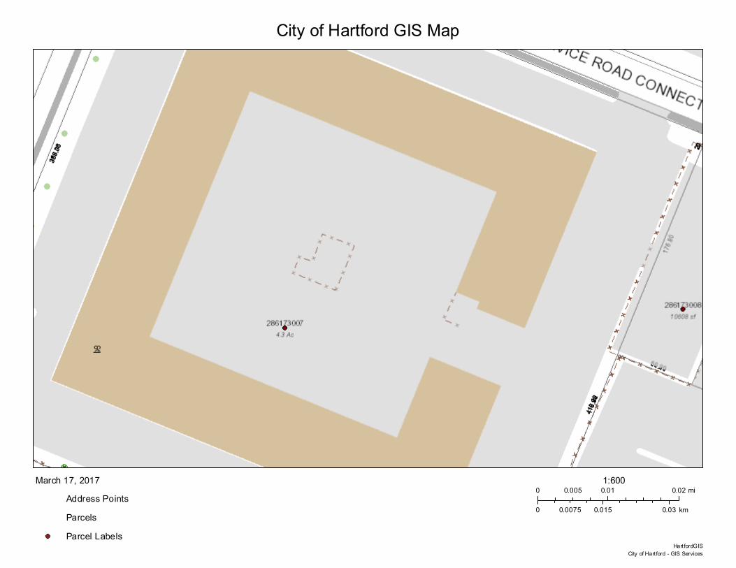
Located at: 92 Weston Street, Hartford, CT 06103
Latitude: 41° 47' 12.3"/ Longitude: -72° 39' 44.42"
Dear Ms. Bachman,
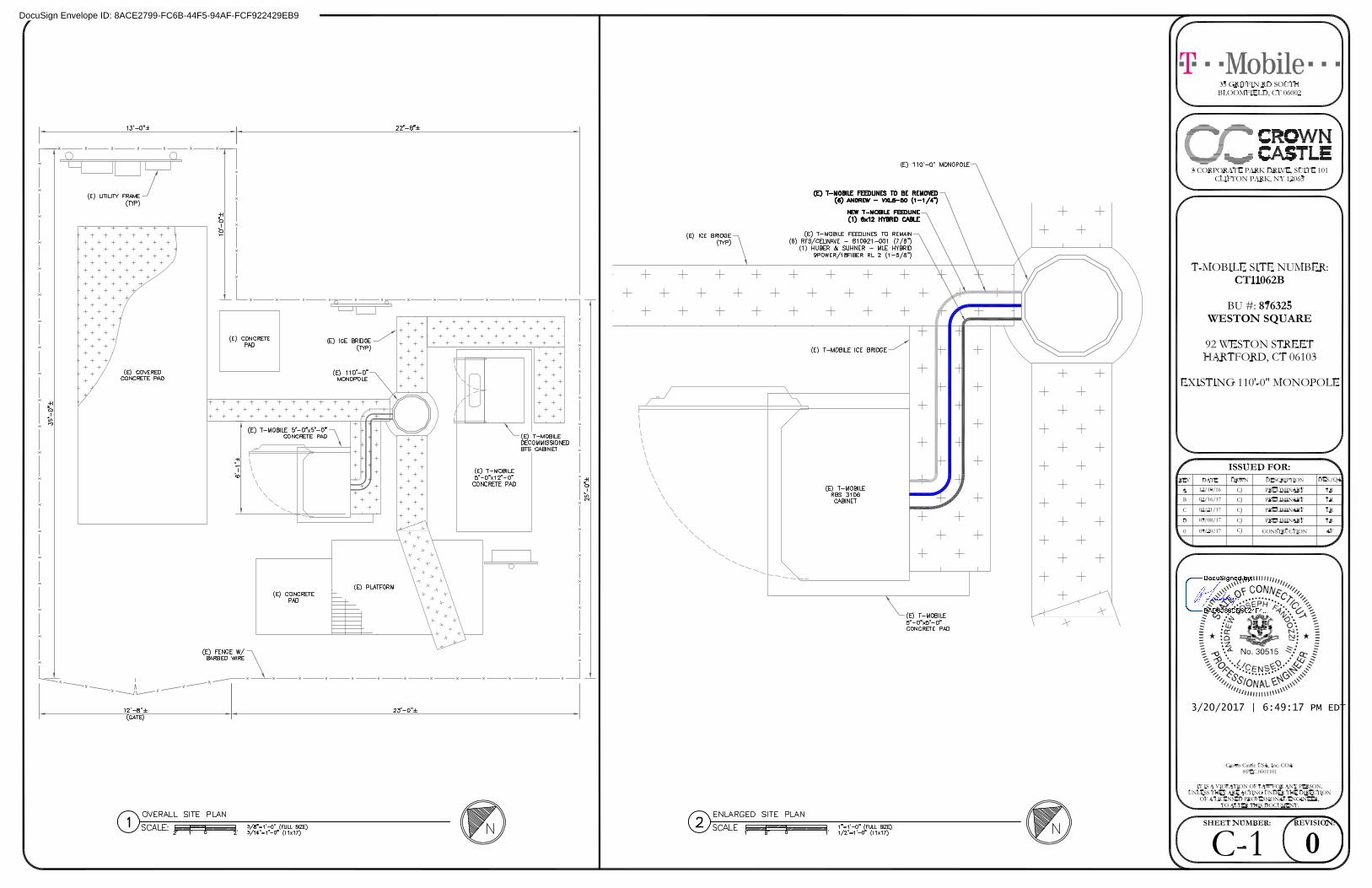
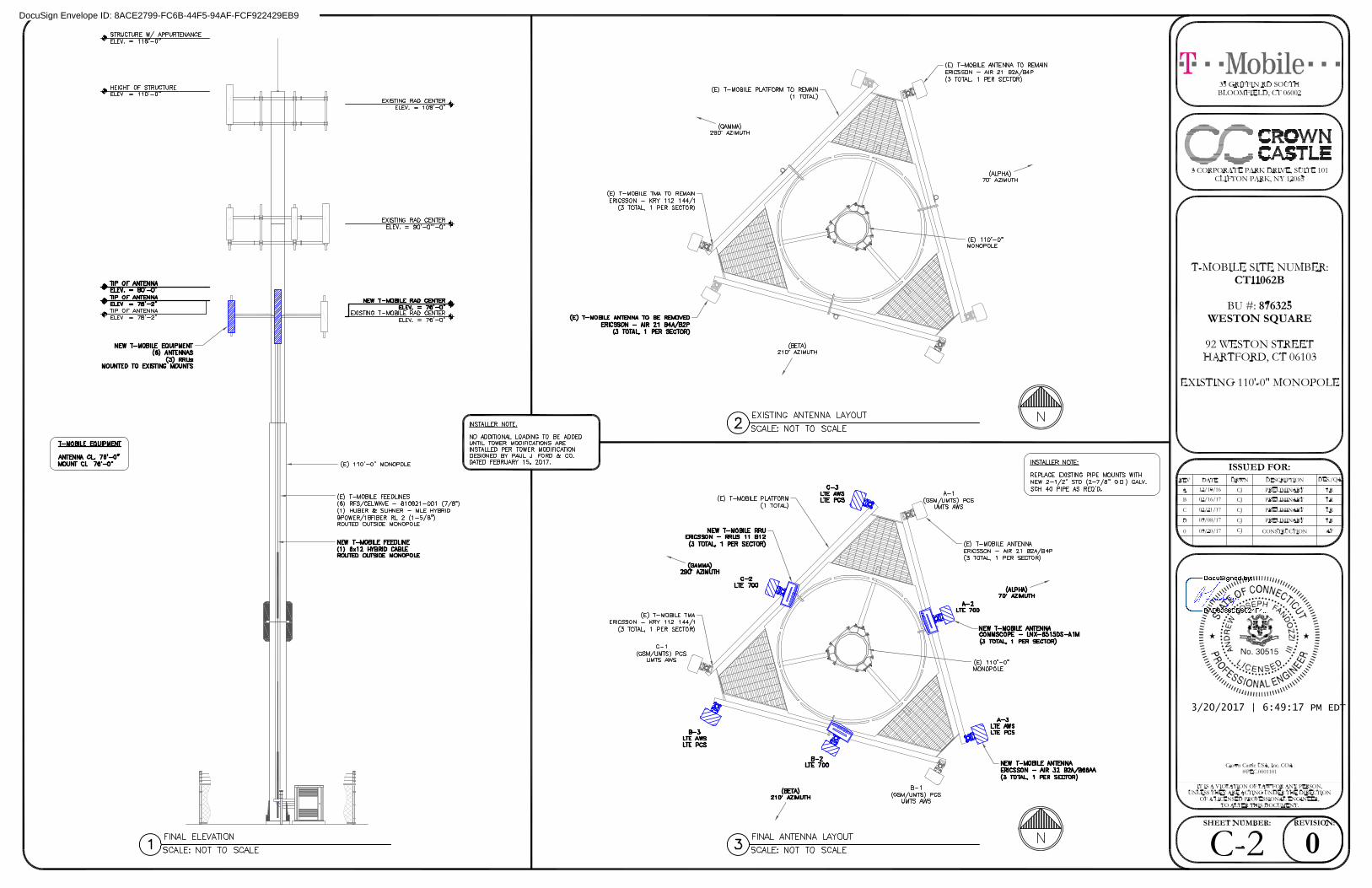
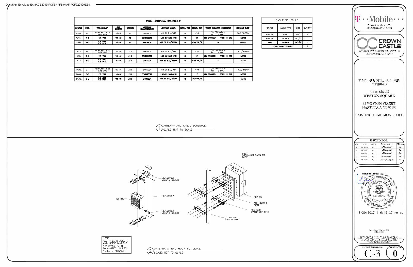
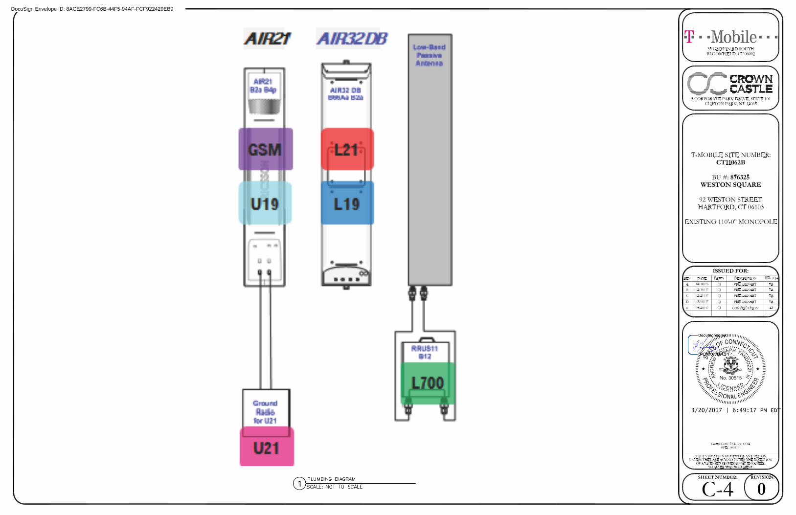
T-Mobile currently maintains three (3) antennas at the 76-foot level of the existing 110-foot monopole
located at 92 Weston Street, Hartford, CT. The tower is owned by Crown Castle. The property is owned
by NEPREO Inc. T-Mobile now intends to add three (3) antennas, replace three (3) antennas, add three
(3) RRHs and one (1) hybrid cable, and remove six (6) lines of coaxial cable at the same 76-foot level.
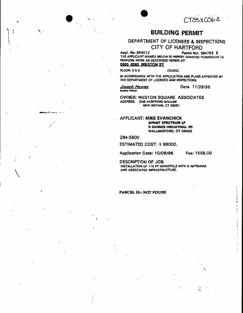
The only document that the town could find for the original approval of the tower was building permit
number 964785E dated November 26, 1996. No conditions were outlined on the permit. A copy of my
request to the town and the permit have been included.
Please accept this letter as notification pursuant to Regulations of Connecticut State Agencies §16-50j-
73, for construction that constitutes an exempt modification pursuant to R.C.S.A. §16-50j-72(b)(2). In
accordance with R.S.C.A. § 16-50j-73, a copy of this letter is being sent to the Honorable Luke Bronin,
Ms. Caitlin Palmer Principle Planner for Commercial Development Planning & Zoning Commission, the
property owner and the tower owner.
1. The proposed modifications will not result in an increase in the height of the existing tower.
Melanie A. Bachman
March 28, 2017
Page 2
2. The proposed modification will not require the extension of the site boundary.
3. The proposed modification will not increase noise levels at the facility by six decibels or more,
or to levels that exceed state and local criteria.
4. The operation of the replacement antennas will not increase radio frequency emissions at the
facility to a level at or above the Federal Communication Commission safety standard.
5. The proposed modifications will not cause a change or alteration in the physical or
environmental characteristics of the site.
6. The existing structure and its foundation can support the proposed loading.
For the foregoing reasons, T-Mobile respectfully submits that the proposed modifications to the above-
referenced telecommunications facility constitutes an exempt modification under R.C.S.A. § 16-50j-
72(b)(2). Please send approval/rejection letter to Attn: Amanda Cornwall.
Sincerely,
Amanda Cornwall
Real Estate Specialist
12 Gill Street, Suite 5800, Woburn, MA 01801
339-205-7017
Attachments:
Tab 1: Exhibit-1: Compound plan and elevation depicting the planned changes
Tab 2: Exhibit-2: Structural Modification Report
Tab 3: Exhibit-3: General Power Density Table report (RF Emissions Analysis Report)
Melanie A. Bachman
March 28, 2017
Page 3
cc: Mayor Luke Bronin
Office of the Mayor
550 Main Street, Room 200
Hartford, CT 06103
Ms. Caitlin Palmer Principle Planner for Commercial Development
Planning & Zoning Commission
250 Constitution Plaza, 4th Floor
Hartford, CT 06103
Crown Castle (Tower Owner)
12 Gill Street, Suite 5800
Woburn, Ma 01801
NEPREO INC (Property Owner)
337 Freeport Street
Boston, MA 02122

1
Cornwall, Amanda
From: Goodall, AmandaSent: Thursday, February 16, 2017 9:28 AMTo: [email protected]: Cell Tower-92 Weston StreetAttachments: emfilingmemo111015.pdf
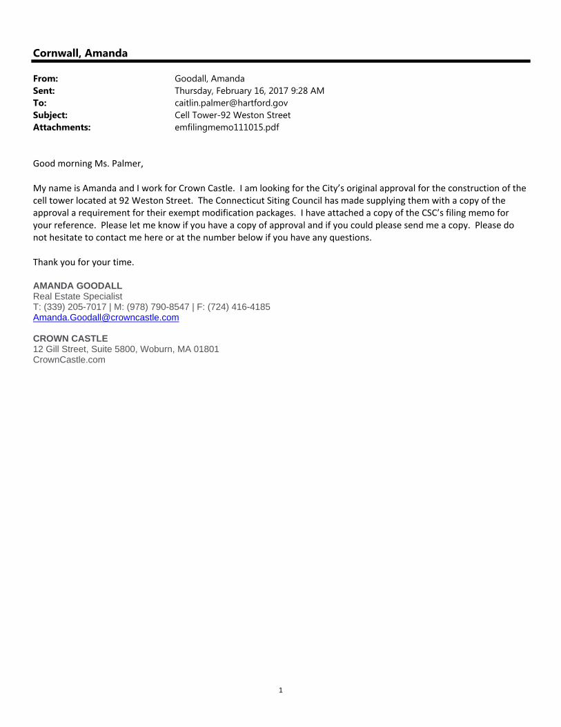
Good morning Ms. Palmer, My name is Amanda and I work for Crown Castle. I am looking for the City’s original approval for the construction of the cell tower located at 92 Weston Street. The Connecticut Siting Council has made supplying them with a copy of the approval a requirement for their exempt modification packages. I have attached a copy of the CSC’s filing memo for your reference. Please let me know if you have a copy of approval and if you could please send me a copy. Please do not hesitate to contact me here or at the number below if you have any questions. Thank you for your time. AMANDA GOODALL Real Estate Specialist T: (339) 205-7017 | M: (978) 790-8547 | F: (724) 416-4185 [email protected] CROWN CASTLE 12 Gill Street, Suite 5800, Woburn, MA 01801 CrownCastle.com
1
Cornwall, Amanda
From: [email protected]: [email protected]: Friday, March 17, 2017 10:04 AMSubject: Delivered: 92 Weston Street-Cell Tower
Your message has been delivered to the following recipients: [email protected] Subject: 92 Weston Street-Cell Tower
City of Hartford GIS Map
Address PointsParcelsParcel Labels
March 17, 20170 0.01 0.020.005 mi
0 0.015 0.030.0075 km
1:600
City of Hart ford - GIS ServicesHart fordGIS

3/17/2017 Unofficial Property Record Card
http://assessor1.hartford.gov/RecordCard.asp 1/1
Unofficial Property Record Card City of Hartford, CTGeneral Property Data
Parcel Identification 286173007 Property Owner NEPREO INC Property Location 0092 WESTON ST HARTFORD
Property Use WAREHOUSEMailing Address 337 FREEPORT ST Most Recent Sale Date 11/3/2016
Legal Reference 071300299City BOSTON Grantor ALBEMARLE WESTON STREET LLC,
Mailing State MA Zip 02122 Sale Price 0ParcelZoning ID1 Land Area 4.301 acres
Current Property Assessment
Fiscal Year 2016Land Value 886,480
Total Value 1,771,490Building Value 825,230
Building Description
Building Style OFFICE/WHS Foundation Type Concrete Flooring Type COMBINATION# of Living Units 0 Frame Type Steel Basement Floor N/A
Year Built 1978 Roof Structure FLAT Heating Type Warm AirBuilding Grade Average Roof Cover Metal Heating Fuel Gas
Building Condition Average Siding Brick Air Conditioning 30%Finished Area (SF) 48012 Interior Walls DRYWALL # of Bsmt Garages 0
Number Rooms 0 Number Beds 0 # of Full Baths 0# of 3/4 Baths 0 # of 1/2 Baths 0 # of Other Fixtures 0
Legal Description
Narrative Description of PropertyThis property contains 4.301 acres of land mainly classified as WAREHOUSE with a(n) OFFICE/WHS style building, built about 1978 , having Brickexterior and Metal roof cover, with 0 unit(s), 0 room(s), 0 bedroom(s), 0 bath(s), 0 half bath(s).
Property Images
Disclaimer: This information is believed to be correct but is subject to change and is not warranteed.

DocuSign Envelope ID: 8ACE2799-FC6B-44F5-94AF-FCF922429EB9
3/20/2017 | 6:49:17 PM EDT
DocuSign Envelope ID: 8ACE2799-FC6B-44F5-94AF-FCF922429EB9
3/20/2017 | 6:49:17 PM EDT
DocuSign Envelope ID: 8ACE2799-FC6B-44F5-94AF-FCF922429EB9
3/20/2017 | 6:49:17 PM EDT
DocuSign Envelope ID: 8ACE2799-FC6B-44F5-94AF-FCF922429EB9
3/20/2017 | 6:49:17 PM EDT
DocuSign Envelope ID: 8ACE2799-FC6B-44F5-94AF-FCF922429EB9
3/20/2017 | 6:49:17 PM EDT
DocuSign Envelope ID: 8ACE2799-FC6B-44F5-94AF-FCF922429EB9
3/20/2017 | 6:49:17 PM EDT
DocuSign Envelope ID: 8ACE2799-FC6B-44F5-94AF-FCF922429EB9
3/20/2017 | 6:49:17 PM EDT
DocuSign Envelope ID: 8ACE2799-FC6B-44F5-94AF-FCF922429EB9
3/20/2017 | 6:49:17 PM EDT
DocuSign Envelope ID: 8ACE2799-FC6B-44F5-94AF-FCF922429EB9
3/20/2017 | 6:49:17 PM EDT
DocuSign Envelope ID: 8ACE2799-FC6B-44F5-94AF-FCF922429EB9
3/20/2017 | 6:49:17 PM EDT
tnxTower Report - version 7.0.5.1
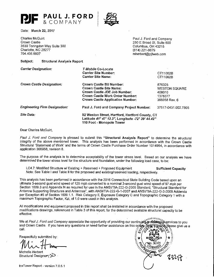
Date: March 22, 2017
Charles McGuirt Paul J. Ford and CompanyCrown Castle 250 E Broad St, Suite 6003530 Toringdon Way Suite 300 Columbus, OH 43215Charlotte, NC 28277 (614) 221-6679704.405.6607 [email protected]
Subject: Structural Analysis Report
Carrier Designation: T-Mobile Co-LocateCarrier Site Number: CT11062BCarrier Site Name: CT11062B
Crown Castle Designation: Crown Castle BU Number: 876325Crown Castle Site Name: WESTON SQUARECrown Castle JDE Job Number: 408010Crown Castle Work Order Number: 1378377Crown Castle Application Number: 366958 Rev. 6
Engineering Firm Designation: Paul J. Ford and Company Project Number: 37517-0431.002.7805
Site Data: 92 Weston Street, Hartford, Hartford County, CTLatitude 41° 47' 12.3'', Longitude -72° 39' 44.42''110 Foot - Monopole Tower
Dear Charles McGuirt,
Paul J. Ford and Company is pleased to submit this “Structural Analysis Report” to determine the structuralintegrity of the above mentioned tower. This analysis has been performed in accordance with the Crown CastleStructural ‘Statement of Work’ and the terms of Crown Castle Purchase Order Number 1014984, in accordance withapplication 366958, revision 6.
The purpose of the analysis is to determine acceptability of the tower stress level. Based on our analysis we havedetermined the tower stress level for the structure and foundation, under the following load case, to be:
LC4.7: Modified Structure w/ Existing + Reserved + Proposed Equipment Sufficient CapacityNote: See Table I and Table II for the proposed and existing/reserved loading, respectively.
This analysis has been performed in accordance with the 2016 Connecticut State Building Code based upon anultimate 3-second gust wind speed of 125 mph converted to a nominal 3-second gust wind speed of 97 mph perSection 1609.3 and Appendix N as required for use in the ANSI/TIA-222-G-2005 Standard, “Structural Standard forAntenna Supporting Structures and Antennas”, with ANSI/TIA-222-G-1-2007 and ANSI/TIA-222-G-2-2009 Addendaper Exception #5 of Section 1609.1.1. Risk Category II, Exposure Category C and Topographic Category 1 with amaximum Topographic Factor, Kzt, of 1.0 were used in this analysis.
All modifications and equipment proposed in this report shall be installed in accordance with the proposedmodifications drawings, referenced in Table 3 of this report, for the determined available structural capacity to beeffective.
We at Paul J. Ford and Company appreciate the opportunity of providing our continuing professional services to youand Crown Castle. If you have any questions or need further assistance on this or any other projects please give us acall.
Respectfully submitted by:
Michelle HerbertStructural Designer
March 22, 2017110 Ft Monopole Tower Structural Analysis CCI BU No 876325Project Number 37517-0431.002.7805, Application 366958, Revision 6 Page 2
tnxTower Report - version 7.0.5.1
TABLE OF CONTENTS
1) INTRODUCTION
2) ANALYSIS CRITERIATable 1 - Proposed Antenna and Cable InformationTable 2 - Existing and Reserved Antenna and Cable Information
3) ANALYSIS PROCEDURETable 3 - Documents Provided3.1) Analysis Method3.2) Assumptions
4) ANALYSIS RESULTSTable 4 - Section Capacity (Summary)Table 5 – Tower Components vs. Capacity4.1) Recommendations
5) APPENDIX AtnxTower Output
6) APPENDIX BBase Level Drawing
7) APPENDIX CAdditional Calculations
March 22, 2017110 Ft Monopole Tower Structural Analysis CCI BU No 876325Project Number 37517-0431.002.7805, Application 366958, Revision 6 Page 3
tnxTower Report - version 7.0.5.1
1) INTRODUCTION
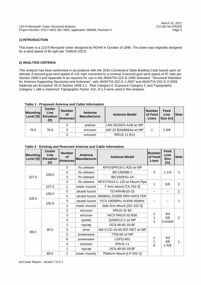
This tower is a 110 ft Monopole tower designed by ROHN in October of 1996. The tower was originally designedfor a wind speed of 85 mph per TIA/EIA-222-E.
2) ANALYSIS CRITERIA
This analysis has been performed in accordance with the 2016 Connecticut State Building Code based upon anultimate 3-second gust wind speed of 125 mph converted to a nominal 3-second gust wind speed of 97 mph perSection 1609.3 and Appendix N as required for use in the ANSI/TIA-222-G-2005 Standard, “Structural Standardfor Antenna Supporting Structures and Antennas”, with ANSI/TIA-222-G-1-2007 and ANSI/TIA-222-G-2-2009Addenda per Exception #5 of Section 1609.1.1. Risk Category II, Exposure Category C and TopographicCategory 1 with a maximum Topographic Factor, Kzt, of 1.0 were used in this analysis.
Table 1 - Proposed Antenna and Cable Information
MountingLevel (ft)
CenterLine
Elevation(ft)
Numberof
Antennas
AntennaManufacturer
Antenna ModelNumberof FeedLines
FeedLine
Size (in)Note
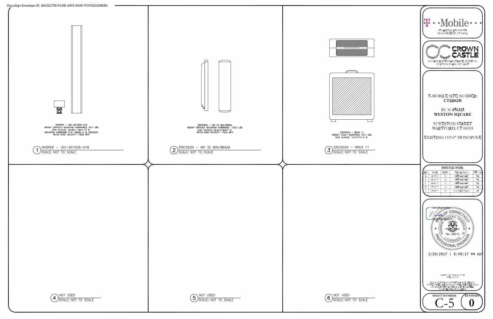
76.0 76.0
3 andrew LNX-6515DS-A1M w/ MP
1 1-5/83 ericsson AIR 32 B2a/B66Aa w/ MP
3 ericsson RRUS 11 B12
Table 2 - Existing and Reserved Antenna and Cable Information
MountingLevel (ft)
CenterLine
Elevation(ft)
Numberof
Antennas
AntennaManufacturer
Antenna ModelNumberof FeedLines
FeedLineSize(in)
Note
107.0108.0
3 rfs celwave APXVSPP18-C-A20 w/ MP
3 1-1/4 13 rfs celwave IBC1900BB-1
3 rfs celwave IBC1900HG-2A
3 rfs celwave APXVTM14-C-120 w/ Mount Pipe1 5/8 2
107.0 1 tower mounts T-Arm Mount [TA 702-3]
105.0
106.03 alcatel lucent TD-RRH8x20-25 -- -- 2
3 alcatel lucent 800MHz 2X50W RRH W/FILTER
-- -- 1105.0
3 alcatel lucent PCS 1900MHz 4x45W-65MHz
1 tower mounts Side Arm Mount [SO 102-3]
89.090.0
3 ericsson RRUS 32 B2211
3/43/8
Conduit2
3 ericsson WCS RRUS-32-B30
3 quintel QS66512-2 w/ MP
1 raycap DC6-48-60-18-8F
3 kmw AM-X-CD-16-65-00T-RET w/ MP
216
3/43/8
1-5/81
3 powerwave 7750.00 w/ MP
6 powerwave LGP21401
3 ericsson RRUS-11
1 raycap DC6-48-60-18-8F
89.0 1 tower mounts Platform Mount [LP 502-1]
March 22, 2017110 Ft Monopole Tower Structural Analysis CCI BU No 876325Project Number 37517-0431.002.7805, Application 366958, Revision 6 Page 4
tnxTower Report - version 7.0.5.1
MountingLevel (ft)
CenterLine
Elevation(ft)
Numberof
Antennas
AntennaManufacturer
Antenna ModelNumberof FeedLines
FeedLineSize(in)
Note
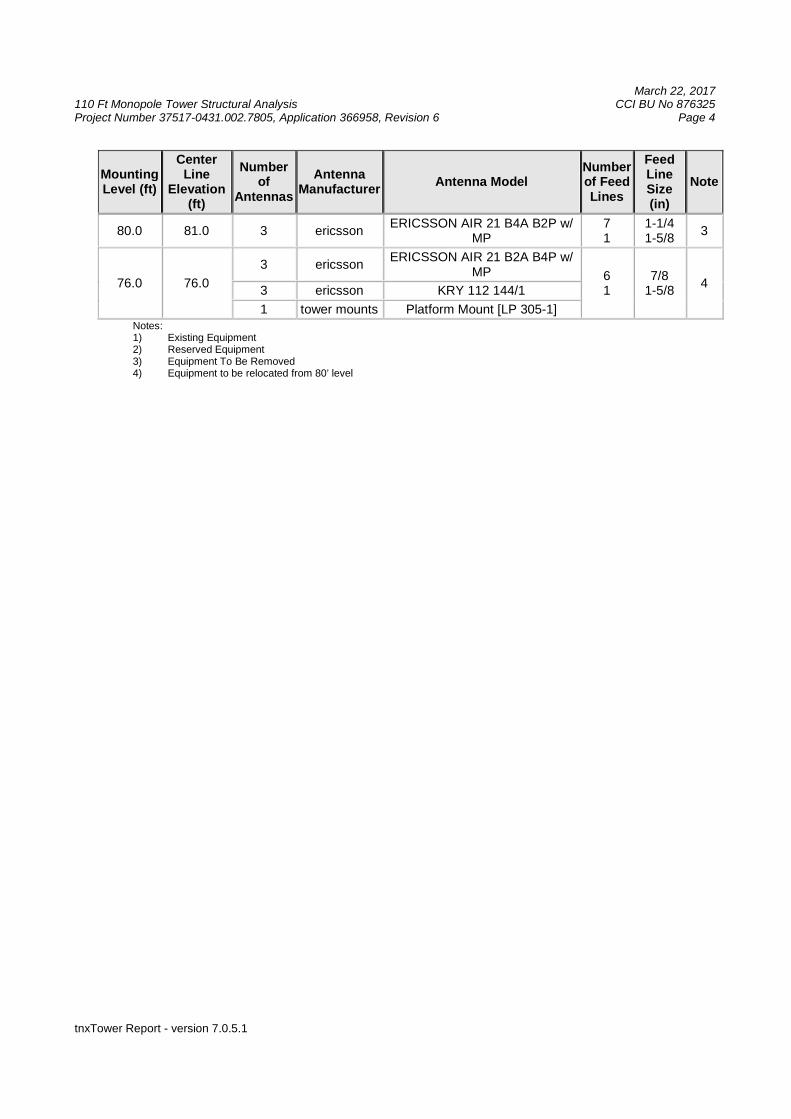
80.0 81.0 3 ericssonERICSSON AIR 21 B4A B2P w/
MP71
1-1/41-5/8
3
76.0 76.0
3 ericssonERICSSON AIR 21 B2A B4P w/
MP 61
7/81-5/8
43 ericsson KRY 112 144/1
1 tower mounts Platform Mount [LP 305-1]Notes:1) Existing Equipment2) Reserved Equipment3) Equipment To Be Removed4) Equipment to be relocated from 80’ level
March 22, 2017110 Ft Monopole Tower Structural Analysis CCI BU No 876325Project Number 37517-0431.002.7805, Application 366958, Revision 6 Page 5
tnxTower Report - version 7.0.5.1
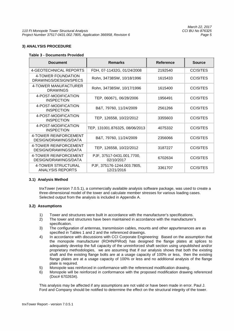
3) ANALYSIS PROCEDURE
Table 3 - Documents Provided
Document Remarks Reference Source
4-GEOTECHNICAL REPORTS FDH, 07-11432G, 01/24/2008 2192540 CCISITES
4-TOWER FOUNDATIONDRAWINGS/DESIGN/SPECS
Rohn, 34738SW, 10/18/1996 1615433 CCISITES
4-TOWER MANUFACTURERDRAWINGS
Rohn, 34738SW, 10/17/1996 1615400 CCISITES
4-POST-MODIFICATIONINSPECTION
TEP, 060671, 06/28/2006 1956491 CCISITES
4-POST-MODIFICATIONINSPECTION
B&T, 79760, 11/24/2009 2561266 CCISITES
4-POST-MODIFICATIONINSPECTION
TEP, 126558, 10/22/2012 3355603 CCISITES
4-POST-MODIFICATIONINSPECTION
TEP, 131001.876325, 08/06/2013 4075332 CCISITES
4-TOWER REINFORCEMENTDESIGN/DRAWINGS/DATA
B&T, 79760, 11/24/2009 2356066 CCISITES
4-TOWER REINFORCEMENTDESIGN/DRAWINGS/DATA
TEP, 126558, 10/22/2012 3187227 CCISITES
4-TOWER REINFORCEMENTDESIGN/DRAWINGS/DATA
PJF, 37517-0431.001.7700,02/10/2017
6702634 CCISITES
4-TOWER STRUCTURALANALYSIS REPORTS
PJF, 375176-1244.003.7805,12/21/2016
3361707 CCISITES
3.1) Analysis Method
tnxTower (version 7.0.5.1), a commercially available analysis software package, was used to create athree-dimensional model of the tower and calculate member stresses for various loading cases.Selected output from the analysis is included in Appendix A.
3.2) Assumptions
1) Tower and structures were built in accordance with the manufacturer’s specifications.2) The tower and structures have been maintained in accordance with the manufacturer’s
specification.3) The configuration of antennas, transmission cables, mounts and other appurtenances are as
specified in Tables 1 and 2 and the referenced drawings.4) In accordance with discussions with CCI Corporate Engineering: Based on the assumption that
the monopole manufacturer (ROHN/PiRod) has designed the flange plates at splices toadequately develop the full capacity of the unreinforced shaft section using unpublished and/orproprietary methodologies, we are assuming that if our analysis shows that both the existingshaft and the existing flange bolts are at a usage capacity of 100% or less, then the existingflange plates are at a usage capacity of 100% or less and no additional analysis of the flangeplate is required.
5) Monopole was reinforced in conformance with the referenced modification drawing.6) Monopole will be reinforced in conformance with the proposed modification drawing referenced
(Doc# 6702634).
This analysis may be affected if any assumptions are not valid or have been made in error. Paul J.Ford and Company should be notified to determine the effect on the structural integrity of the tower.
March 22, 2017110 Ft Monopole Tower Structural Analysis CCI BU No 876325Project Number 37517-0431.002.7805, Application 366958, Revision 6 Page 6
tnxTower Report - version 7.0.5.1
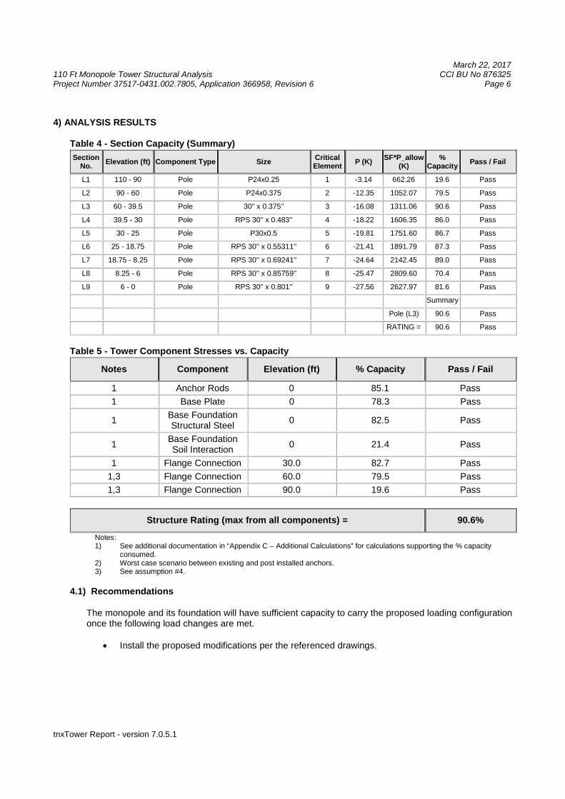
4) ANALYSIS RESULTS
Table 4 - Section Capacity (Summary)
SectionNo.
Elevation (ft) Component Type SizeCriticalElement
P (K)SF*P_allow
(K)%
CapacityPass / Fail
L1 110 - 90 Pole P24x0.25 1 -3.14 662.26 19.6 Pass
L2 90 - 60 Pole P24x0.375 2 -12.35 1052.07 79.5 Pass
L3 60 - 39.5 Pole 30'' x 0.375'' 3 -16.08 1311.06 90.6 Pass
L4 39.5 - 30 Pole RPS 30'' x 0.483'' 4 -18.22 1606.35 86.0 Pass
L5 30 - 25 Pole P30x0.5 5 -19.81 1751.60 86.7 Pass
L6 25 - 18.75 Pole RPS 30'' x 0.55311'' 6 -21.41 1891.79 87.3 Pass
L7 18.75 - 8.25 Pole RPS 30'' x 0.69241'' 7 -24.64 2142.45 89.0 Pass
L8 8.25 - 6 Pole RPS 30'' x 0.85759'' 8 -25.47 2809.60 70.4 Pass
L9 6 - 0 Pole RPS 30'' x 0.801'' 9 -27.56 2627.97 81.6 Pass
Summary
Pole (L3) 90.6 Pass
RATING = 90.6 Pass
Table 5 - Tower Component Stresses vs. Capacity
Notes Component Elevation (ft) % Capacity Pass / Fail
1 Anchor Rods 0 85.1 Pass
1 Base Plate 0 78.3 Pass
1Base FoundationStructural Steel
0 82.5 Pass
1Base FoundationSoil Interaction
0 21.4 Pass
1 Flange Connection 30.0 82.7 Pass
1,3 Flange Connection 60.0 79.5 Pass
1,3 Flange Connection 90.0 19.6 Pass
Structure Rating (max from all components) = 90.6%
Notes:1) See additional documentation in “Appendix C – Additional Calculations” for calculations supporting the % capacity
consumed.2) Worst case scenario between existing and post installed anchors.3) See assumption #4.
4.1) Recommendations
The monopole and its foundation will have sufficient capacity to carry the proposed loading configurationonce the following load changes are met.
Install the proposed modifications per the referenced drawings.
March 22, 2017110 Ft Monopole Tower Structural Analysis CCI BU No 876325Project Number 37517-0431.002.7805, Application 366958, Revision 6 Page 7
tnxTower Report - version 7.0.5.1
APPENDIX A
TNXTOWER OUTPUT
March 22, 2017110 Ft Monopole Tower Structural Analysis CCI BU No 876325Project Number 37517-0431.002.7805, Application 366958, Revision 6 Page 8
tnxTower Report - version 7.0.5.1
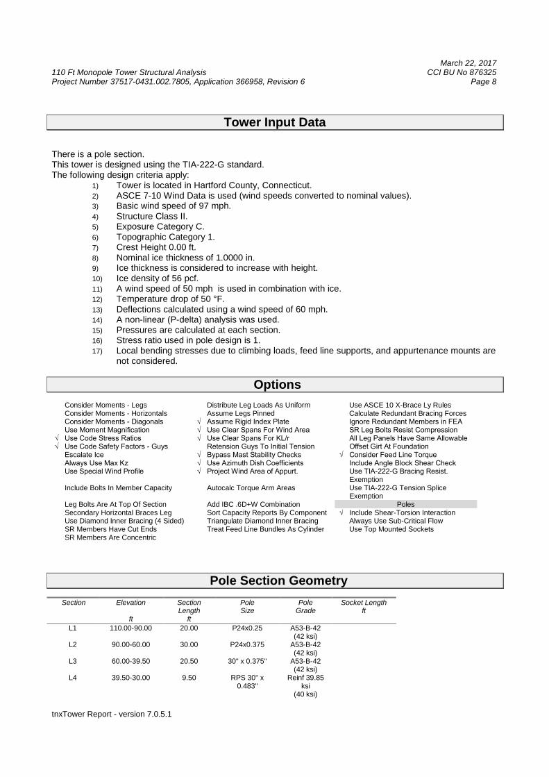
Tower Input Data
There is a pole section.This tower is designed using the TIA-222-G standard.The following design criteria apply:
1) Tower is located in Hartford County, Connecticut.2) ASCE 7-10 Wind Data is used (wind speeds converted to nominal values).3) Basic wind speed of 97 mph.4) Structure Class II.5) Exposure Category C.6) Topographic Category 1.7) Crest Height 0.00 ft.8) Nominal ice thickness of 1.0000 in.9) Ice thickness is considered to increase with height.10) Ice density of 56 pcf.11) A wind speed of 50 mph is used in combination with ice.12) Temperature drop of 50 °F.13) Deflections calculated using a wind speed of 60 mph.14) A non-linear (P-delta) analysis was used.15) Pressures are calculated at each section.16) Stress ratio used in pole design is 1.17) Local bending stresses due to climbing loads, feed line supports, and appurtenance mounts are
not considered.
Options
Consider Moments - Legs Distribute Leg Loads As Uniform Use ASCE 10 X-Brace Ly RulesConsider Moments - Horizontals Assume Legs Pinned Calculate Redundant Bracing Forces
Consider Moments - Diagonals √ Assume Rigid Index Plate Ignore Redundant Members in FEA Use Moment Magnification √ Use Clear Spans For Wind Area SR Leg Bolts Resist Compression √ Use Code Stress Ratios √ Use Clear Spans For KL/r All Leg Panels Have Same Allowable √ Use Code Safety Factors - Guys Retension Guys To Initial Tension Offset Girt At Foundation Escalate Ice √ Bypass Mast Stability Checks √ Consider Feed Line Torque Always Use Max Kz √ Use Azimuth Dish Coefficients Include Angle Block Shear Check Use Special Wind Profile √ Project Wind Area of Appurt. Use TIA-222-G Bracing Resist.
ExemptionInclude Bolts In Member Capacity Autocalc Torque Arm Areas Use TIA-222-G Tension Splice
ExemptionLeg Bolts Are At Top Of Section Add IBC .6D+W Combination PolesSecondary Horizontal Braces Leg Sort Capacity Reports By Component √ Include Shear-Torsion InteractionUse Diamond Inner Bracing (4 Sided) Triangulate Diamond Inner Bracing Always Use Sub-Critical FlowSR Members Have Cut Ends Treat Feed Line Bundles As Cylinder Use Top Mounted SocketsSR Members Are Concentric
Pole Section Geometry
Section Elevation
ft
SectionLength
ft
PoleSize
PoleGrade
Socket Lengthft
L1 110.00-90.00 20.00 P24x0.25 A53-B-42(42 ksi)
L2 90.00-60.00 30.00 P24x0.375 A53-B-42(42 ksi)
L3 60.00-39.50 20.50 30'' x 0.375'' A53-B-42(42 ksi)
L4 39.50-30.00 9.50 RPS 30'' x0.483''
Reinf 39.85ksi
(40 ksi)
March 22, 2017110 Ft Monopole Tower Structural Analysis CCI BU No 876325Project Number 37517-0431.002.7805, Application 366958, Revision 6 Page 9
tnxTower Report - version 7.0.5.1
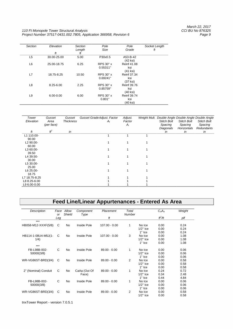
Section Elevation
ft
SectionLength
ft
PoleSize
PoleGrade
Socket Lengthft
L5 30.00-25.00 5.00 P30x0.5 A53-B-42(42 ksi)
L6 25.00-18.75 6.25 RPS 30'' x0.55311''
Reinf 41.08ksi
(41 ksi)L7 18.75-8.25 10.50 RPS 30'' x
0.69241''Reinf 37.34
ksi(37 ksi)
L8 8.25-6.00 2.25 RPS 30'' x0.85759''
Reinf 39.76ksi
(40 ksi)L9 6.00-0.00 6.00 RPS 30'' x
0.801''Reinf 39.74
ksi(40 ksi)
TowerElevation
ft
GussetArea
(per face)
ft2
GussetThickness
in
Gusset GradeAdjust. FactorAf
Adjust.Factor
Ar
Weight Mult. Double AngleStitch BoltSpacing
Diagonalsin
Double AngleStitch BoltSpacing
Horizontalsin
Double AngleStitch BoltSpacing
Redundantsin
L1 110.00-90.00
1 1 1
L2 90.00-60.00
1 1 1
L3 60.00-39.50
1 1 1
L4 39.50-30.00
1 1 1
L5 30.00-25.00
1 1 1
L6 25.00-18.75
1 1 1
L7 18.75-8.25 1 1 1L8 8.25-6.00 1 1 1L9 6.00-0.00 1 1 1
Feed Line/Linear Appurtenances - Entered As Area
Description Faceor
Leg
AllowShield
ComponentType
Placement
ft
TotalNumber
CAAA
ft2/ft
Weight
plf
***HB058-M12-XXXF(5/8) C No Inside Pole 107.00 - 0.00 1 No Ice
1/2'' Ice1'' Ice
0.000.000.00
0.240.240.24
HB114-1-08U4-M5J(1-1/4)
C No Inside Pole 107.00 - 0.00 3 No Ice1/2'' Ice1'' Ice
0.000.000.00
1.081.081.08
***FB-L98B-002-
50000(3/8)C No Inside Pole 89.00 - 0.00 1 No Ice
1/2'' Ice1'' Ice
0.000.000.00
0.060.060.06
WR-VG86ST-BRD(3/4) C No Inside Pole 89.00 - 0.00 2 No Ice1/2'' Ice1'' Ice
0.000.000.00
0.580.580.58
2'' (Nominal) Conduit C No CaAa (Out OfFace)
89.00 - 0.00 1 No Ice1/2'' Ice1'' Ice
0.240.340.44
0.722.484.84
FB-L98B-002-50000(3/8)
C No Inside Pole 89.00 - 0.00 1 No Ice1/2'' Ice1'' Ice
0.000.000.00
0.060.060.06
WR-VG86ST-BRD(3/4) C No Inside Pole 89.00 - 0.00 2 No Ice1/2'' Ice
0.000.00
0.580.58
March 22, 2017110 Ft Monopole Tower Structural Analysis CCI BU No 876325Project Number 37517-0431.002.7805, Application 366958, Revision 6 Page 10
tnxTower Report - version 7.0.5.1
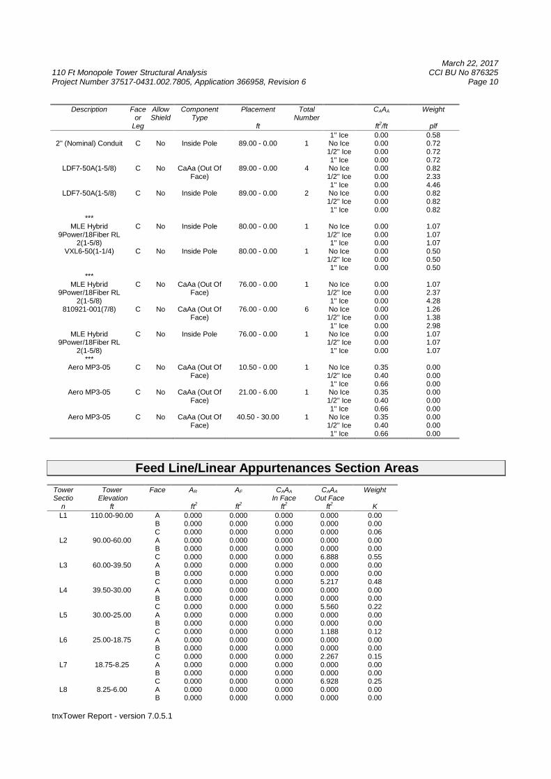
Description Faceor
Leg
AllowShield
ComponentType
Placement
ft
TotalNumber
CAAA
ft2/ft
Weight
plf
1'' Ice 0.00 0.582'' (Nominal) Conduit C No Inside Pole 89.00 - 0.00 1 No Ice
1/2'' Ice1'' Ice
0.000.000.00
0.720.720.72
LDF7-50A(1-5/8) C No CaAa (Out OfFace)
89.00 - 0.00 4 No Ice1/2'' Ice1'' Ice
0.000.000.00
0.822.334.46
LDF7-50A(1-5/8) C No Inside Pole 89.00 - 0.00 2 No Ice1/2'' Ice1'' Ice
0.000.000.00
0.820.820.82
***MLE Hybrid
9Power/18Fiber RL2(1-5/8)
C No Inside Pole 80.00 - 0.00 1 No Ice1/2'' Ice1'' Ice
0.000.000.00
1.071.071.07
VXL6-50(1-1/4) C No Inside Pole 80.00 - 0.00 1 No Ice1/2'' Ice1'' Ice
0.000.000.00
0.500.500.50
***MLE Hybrid
9Power/18Fiber RL2(1-5/8)
C No CaAa (Out OfFace)
76.00 - 0.00 1 No Ice1/2'' Ice1'' Ice
0.000.000.00
1.072.374.28
810921-001(7/8) C No CaAa (Out OfFace)
76.00 - 0.00 6 No Ice1/2'' Ice1'' Ice
0.000.000.00
1.261.382.98
MLE Hybrid9Power/18Fiber RL
2(1-5/8)
C No Inside Pole 76.00 - 0.00 1 No Ice1/2'' Ice1'' Ice
0.000.000.00
1.071.071.07
***Aero MP3-05 C No CaAa (Out Of
Face)10.50 - 0.00 1 No Ice
1/2'' Ice1'' Ice
0.350.400.66
0.000.000.00
Aero MP3-05 C No CaAa (Out OfFace)
21.00 - 6.00 1 No Ice1/2'' Ice1'' Ice
0.350.400.66
0.000.000.00
Aero MP3-05 C No CaAa (Out OfFace)
40.50 - 30.00 1 No Ice1/2'' Ice1'' Ice
0.350.400.66
0.000.000.00
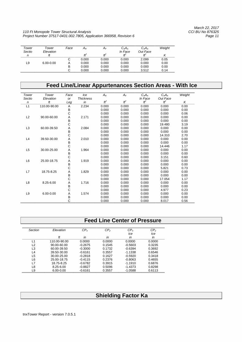
Feed Line/Linear Appurtenances Section Areas
TowerSectio
n
TowerElevation
ft
Face AR
ft2
AF
ft2
CAAA
In Faceft
2
CAAA
Out Faceft
2
Weight
KL1 110.00-90.00 A
BC
0.0000.0000.000
0.0000.0000.000
0.0000.0000.000
0.0000.0000.000
0.000.000.06
L2 90.00-60.00 ABC
0.0000.0000.000
0.0000.0000.000
0.0000.0000.000
0.0000.0006.888
0.000.000.55
L3 60.00-39.50 ABC
0.0000.0000.000
0.0000.0000.000
0.0000.0000.000
0.0000.0005.217
0.000.000.48
L4 39.50-30.00 ABC
0.0000.0000.000
0.0000.0000.000
0.0000.0000.000
0.0000.0005.560
0.000.000.22
L5 30.00-25.00 ABC
0.0000.0000.000
0.0000.0000.000
0.0000.0000.000
0.0000.0001.188
0.000.000.12
L6 25.00-18.75 ABC
0.0000.0000.000
0.0000.0000.000
0.0000.0000.000
0.0000.0002.267
0.000.000.15
L7 18.75-8.25 ABC
0.0000.0000.000
0.0000.0000.000
0.0000.0000.000
0.0000.0006.928
0.000.000.25
L8 8.25-6.00 AB
0.0000.000
0.0000.000
0.0000.000
0.0000.000
0.000.00
March 22, 2017110 Ft Monopole Tower Structural Analysis CCI BU No 876325Project Number 37517-0431.002.7805, Application 366958, Revision 6 Page 11
tnxTower Report - version 7.0.5.1
TowerSectio
n
TowerElevation
ft
Face AR
ft2
AF
ft2
CAAA
In Faceft2
CAAA
Out Faceft2
Weight
K
C 0.000 0.000 0.000 2.099 0.05L9 6.00-0.00 A
BC
0.0000.0000.000
0.0000.0000.000
0.0000.0000.000
0.0000.0003.512
0.000.000.14
Feed Line/Linear Appurtenances Section Areas - With Ice
TowerSectio
n
TowerElevation
ft
Faceor
Leg
IceThickness
in
AR
ft2
AF
ft2
CAAA
In Faceft2
CAAA
Out Faceft2
Weight
K
L1 110.00-90.00 ABC
2.234 0.0000.0000.000
0.0000.0000.000
0.0000.0000.000
0.0000.0000.000
0.000.000.06
L2 90.00-60.00 ABC
2.171 0.0000.0000.000
0.0000.0000.000
0.0000.0000.000
0.0000.00019.480
0.000.003.19
L3 60.00-39.50 ABC
2.084 0.0000.0000.000
0.0000.0000.000
0.0000.0000.000
0.0000.00014.310
0.000.002.70
L4 39.50-30.00 ABC
2.010 0.0000.0000.000
0.0000.0000.000
0.0000.0000.000
0.0000.00014.446
0.000.001.17
L5 30.00-25.00 ABC
1.964 0.0000.0000.000
0.0000.0000.000
0.0000.0000.000
0.0000.0003.151
0.000.000.60
L6 25.00-18.75 ABC
1.919 0.0000.0000.000
0.0000.0000.000
0.0000.0000.000
0.0000.0005.821
0.000.000.73
L7 18.75-8.25 ABC
1.829 0.0000.0000.000
0.0000.0000.000
0.0000.0000.000
0.0000.00017.054
0.000.001.17
L8 8.25-6.00 ABC
1.716 0.0000.0000.000
0.0000.0000.000
0.0000.0000.000
0.0000.0004.977
0.000.000.23
L9 6.00-0.00 ABC
1.574 0.0000.0000.000
0.0000.0000.000
0.0000.0000.000
0.0000.0008.017
0.000.000.56
Feed Line Center of Pressure
Section Elevation
ft
CPX
in
CPZ
in
CPX
Icein
CPZ
Icein
L1 110.00-90.00 0.0000 0.0000 0.0000 0.0000L2 90.00-60.00 -0.2675 0.1545 -0.5603 0.3235L3 60.00-39.50 -0.3000 0.1732 -0.6394 0.3692L4 39.50-30.00 -0.6161 0.3557 -1.1338 0.6546L5 30.00-25.00 -0.2818 0.1627 -0.5920 0.3418L6 25.00-18.75 -0.4115 0.2376 -0.8063 0.4655L7 18.75-8.25 -0.6782 0.3915 -1.1910 0.6876L8 8.25-6.00 -0.8827 0.5096 -1.4373 0.8298L9 6.00-0.00 -0.6161 0.3557 -1.0588 0.6113
Shielding Factor Ka
March 22, 2017110 Ft Monopole Tower Structural Analysis CCI BU No 876325Project Number 37517-0431.002.7805, Application 366958, Revision 6 Page 12
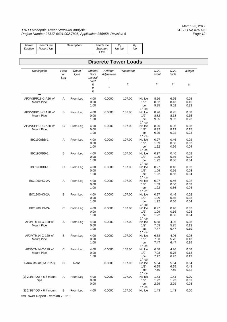
tnxTower Report - version 7.0.5.1
TowerSection
Feed LineRecord No.
Description Feed LineSegment
Elev.
Ka
No IceKa
Ice
Discrete Tower Loads
Description Faceor
Leg
OffsetType
Offsets:Horz
LateralVert
ftftft
AzimuthAdjustmen
t
°
Placement
ft
CAAA
Front
ft2
CAAA
Side
ft2
Weight
K
***APXVSPP18-C-A20 w/
Mount PipeA From Leg 4.00
0.001.00
0.0000 107.00 No Ice1/2''Ice
1'' Ice
8.268.829.35
6.958.139.02
0.080.150.23
APXVSPP18-C-A20 w/Mount Pipe
B From Leg 4.000.001.00
0.0000 107.00 No Ice1/2''Ice
1'' Ice
8.268.829.35
6.958.139.02
0.080.150.23
APXVSPP18-C-A20 w/Mount Pipe
C From Leg 4.000.001.00
0.0000 107.00 No Ice1/2''Ice
1'' Ice
8.268.829.35
6.958.139.02
0.080.150.23
IBC1900BB-1 A From Leg 4.000.001.00
0.0000 107.00 No Ice1/2''Ice
1'' Ice
0.971.091.22
0.460.560.66
0.020.030.04
IBC1900BB-1 B From Leg 4.000.001.00
0.0000 107.00 No Ice1/2''Ice
1'' Ice
0.971.091.22
0.460.560.66
0.020.030.04
IBC1900BB-1 C From Leg 4.000.001.00
0.0000 107.00 No Ice1/2''Ice
1'' Ice
0.971.091.22
0.460.560.66
0.020.030.04
IBC1900HG-2A A From Leg 4.000.001.00
0.0000 107.00 No Ice1/2''Ice
1'' Ice
0.971.091.22
0.460.560.66
0.020.030.04
IBC1900HG-2A B From Leg 4.000.001.00
0.0000 107.00 No Ice1/2''Ice
1'' Ice
0.971.091.22
0.460.560.66
0.020.030.04
IBC1900HG-2A C From Leg 4.000.001.00
0.0000 107.00 No Ice1/2''Ice
1'' Ice
0.971.091.22
0.460.560.66
0.020.030.04
APXVTM14-C-120 w/Mount Pipe
A From Leg 4.000.001.00
0.0000 107.00 No Ice1/2''Ice
1'' Ice
6.587.037.47
4.965.756.47
0.080.130.19
APXVTM14-C-120 w/Mount Pipe
B From Leg 4.000.001.00
0.0000 107.00 No Ice1/2''Ice
1'' Ice
6.587.037.47
4.965.756.47
0.080.130.19
APXVTM14-C-120 w/Mount Pipe
C From Leg 4.000.001.00
0.0000 107.00 No Ice1/2''Ice
1'' Ice
6.587.037.47
4.965.756.47
0.080.130.19
T-Arm Mount [TA 702-3] C None 0.0000 107.00 No Ice1/2''Ice
1'' Ice
5.646.557.46
5.646.557.46
0.340.430.52
(2) 2 3/8'' OD x 6 ft mountpipe
A From Leg 4.000.000.00
0.0000 107.00 No Ice1/2''Ice
1'' Ice
1.431.922.29
1.431.922.29
0.000.010.03
(2) 2 3/8'' OD x 6 ft mount B From Leg 4.00 0.0000 107.00 No Ice 1.43 1.43 0.00
March 22, 2017110 Ft Monopole Tower Structural Analysis CCI BU No 876325Project Number 37517-0431.002.7805, Application 366958, Revision 6 Page 13
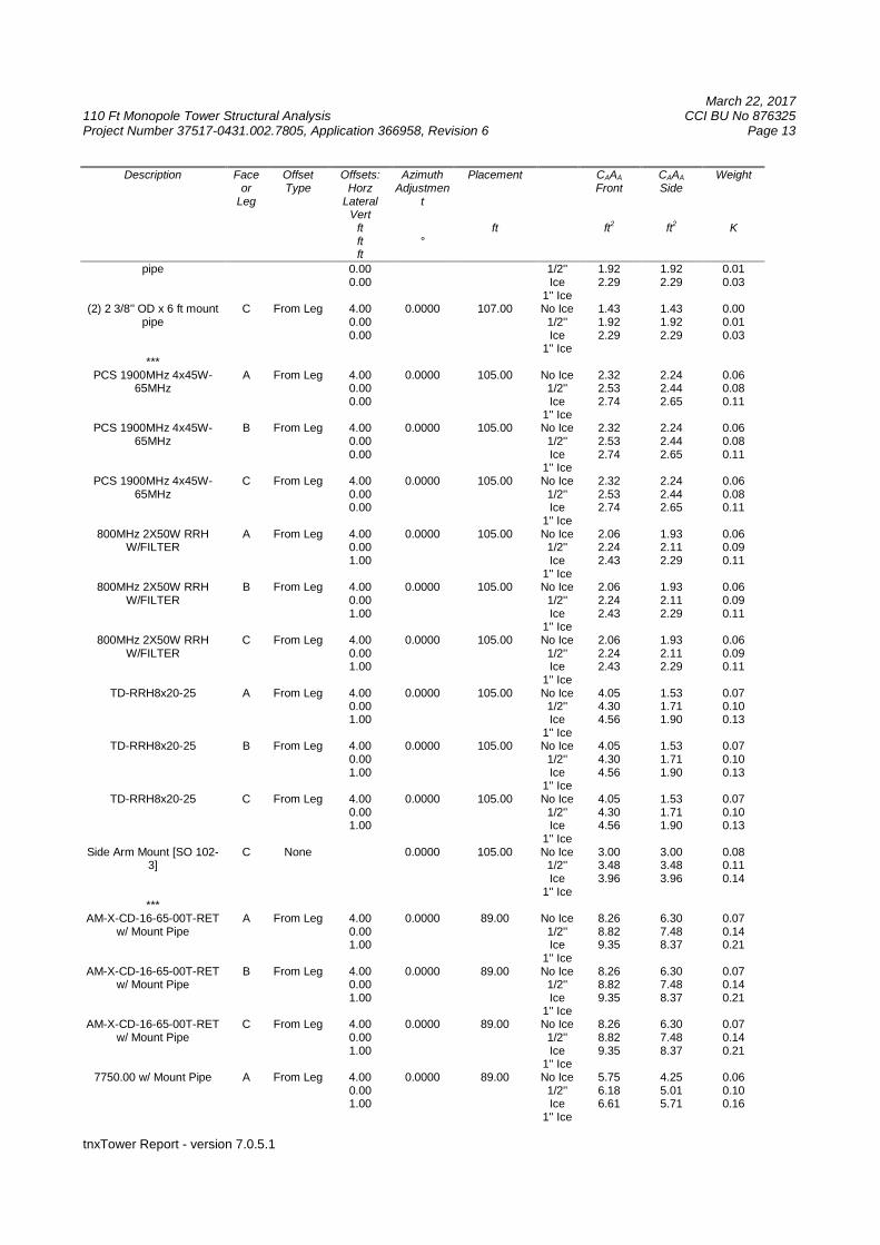
tnxTower Report - version 7.0.5.1
Description Faceor
Leg
OffsetType
Offsets:Horz
LateralVert
ftftft
AzimuthAdjustmen
t
°
Placement
ft
CAAA
Front
ft2
CAAA
Side
ft2
Weight
K
pipe 0.000.00
1/2''Ice
1'' Ice
1.922.29
1.922.29
0.010.03
(2) 2 3/8'' OD x 6 ft mountpipe
C From Leg 4.000.000.00
0.0000 107.00 No Ice1/2''Ice
1'' Ice
1.431.922.29
1.431.922.29
0.000.010.03
***PCS 1900MHz 4x45W-
65MHzA From Leg 4.00
0.000.00
0.0000 105.00 No Ice1/2''Ice
1'' Ice
2.322.532.74
2.242.442.65
0.060.080.11
PCS 1900MHz 4x45W-65MHz
B From Leg 4.000.000.00
0.0000 105.00 No Ice1/2''Ice
1'' Ice
2.322.532.74
2.242.442.65
0.060.080.11
PCS 1900MHz 4x45W-65MHz
C From Leg 4.000.000.00
0.0000 105.00 No Ice1/2''Ice
1'' Ice
2.322.532.74
2.242.442.65
0.060.080.11
800MHz 2X50W RRHW/FILTER
A From Leg 4.000.001.00
0.0000 105.00 No Ice1/2''Ice
1'' Ice
2.062.242.43
1.932.112.29
0.060.090.11
800MHz 2X50W RRHW/FILTER
B From Leg 4.000.001.00
0.0000 105.00 No Ice1/2''Ice
1'' Ice
2.062.242.43
1.932.112.29
0.060.090.11
800MHz 2X50W RRHW/FILTER
C From Leg 4.000.001.00
0.0000 105.00 No Ice1/2''Ice
1'' Ice
2.062.242.43
1.932.112.29
0.060.090.11
TD-RRH8x20-25 A From Leg 4.000.001.00
0.0000 105.00 No Ice1/2''Ice
1'' Ice
4.054.304.56
1.531.711.90
0.070.100.13
TD-RRH8x20-25 B From Leg 4.000.001.00
0.0000 105.00 No Ice1/2''Ice
1'' Ice
4.054.304.56
1.531.711.90
0.070.100.13
TD-RRH8x20-25 C From Leg 4.000.001.00
0.0000 105.00 No Ice1/2''Ice
1'' Ice
4.054.304.56
1.531.711.90
0.070.100.13
Side Arm Mount [SO 102-3]
C None 0.0000 105.00 No Ice1/2''Ice
1'' Ice
3.003.483.96
3.003.483.96
0.080.110.14
***AM-X-CD-16-65-00T-RET
w/ Mount PipeA From Leg 4.00
0.001.00
0.0000 89.00 No Ice1/2''Ice
1'' Ice
8.268.829.35
6.307.488.37
0.070.140.21
AM-X-CD-16-65-00T-RETw/ Mount Pipe
B From Leg 4.000.001.00
0.0000 89.00 No Ice1/2''Ice
1'' Ice
8.268.829.35
6.307.488.37
0.070.140.21
AM-X-CD-16-65-00T-RETw/ Mount Pipe
C From Leg 4.000.001.00
0.0000 89.00 No Ice1/2''Ice
1'' Ice
8.268.829.35
6.307.488.37
0.070.140.21
7750.00 w/ Mount Pipe A From Leg 4.000.001.00
0.0000 89.00 No Ice1/2''Ice
1'' Ice
5.756.186.61
4.255.015.71
0.060.100.16
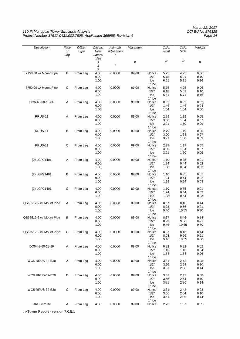
March 22, 2017110 Ft Monopole Tower Structural Analysis CCI BU No 876325Project Number 37517-0431.002.7805, Application 366958, Revision 6 Page 14
tnxTower Report - version 7.0.5.1
Description Faceor
Leg
OffsetType
Offsets:Horz
LateralVert
ftftft
AzimuthAdjustmen
t
°
Placement
ft
CAAA
Front
ft2
CAAA
Side
ft2
Weight
K
7750.00 w/ Mount Pipe B From Leg 4.000.001.00
0.0000 89.00 No Ice1/2''Ice
1'' Ice
5.756.186.61
4.255.015.71
0.060.100.16
7750.00 w/ Mount Pipe C From Leg 4.000.001.00
0.0000 89.00 No Ice1/2''Ice
1'' Ice
5.756.186.61
4.255.015.71
0.060.100.16
DC6-48-60-18-8F A From Leg 4.000.001.00
0.0000 89.00 No Ice1/2''Ice
1'' Ice
0.921.461.64
0.921.461.64
0.020.040.06
RRUS-11 A From Leg 4.000.001.00
0.0000 89.00 No Ice1/2''Ice
1'' Ice
2.793.003.21
1.191.341.50
0.050.070.09
RRUS-11 B From Leg 4.000.001.00
0.0000 89.00 No Ice1/2''Ice
1'' Ice
2.793.003.21
1.191.341.50
0.050.070.09
RRUS-11 C From Leg 4.000.001.00
0.0000 89.00 No Ice1/2''Ice
1'' Ice
2.793.003.21
1.191.341.50
0.050.070.09
(2) LGP21401 A From Leg 4.000.001.00
0.0000 89.00 No Ice1/2''Ice
1'' Ice
1.101.241.38
0.350.440.54
0.010.020.03
(2) LGP21401 B From Leg 4.000.001.00
0.0000 89.00 No Ice1/2''Ice
1'' Ice
1.101.241.38
0.350.440.54
0.010.020.03
(2) LGP21401 C From Leg 4.000.001.00
0.0000 89.00 No Ice1/2''Ice
1'' Ice
1.101.241.38
0.350.440.54
0.010.020.03
QS66512-2 w/ Mount Pipe A From Leg 4.000.001.00
0.0000 89.00 No Ice1/2''Ice
1'' Ice
8.378.939.46
8.469.6610.55
0.140.210.30
QS66512-2 w/ Mount Pipe B From Leg 4.000.001.00
0.0000 89.00 No Ice1/2''Ice
1'' Ice
8.378.939.46
8.469.6610.55
0.140.210.30
QS66512-2 w/ Mount Pipe C From Leg 4.000.001.00
0.0000 89.00 No Ice1/2''Ice
1'' Ice
8.378.939.46
8.469.6610.55
0.140.210.30
DC6-48-60-18-8F A From Leg 4.000.001.00
0.0000 89.00 No Ice1/2''Ice
1'' Ice
0.921.461.64
0.921.461.64
0.020.040.06
WCS RRUS-32-B30 A From Leg 4.000.001.00
0.0000 89.00 No Ice1/2''Ice
1'' Ice
3.313.563.81
2.422.642.86
0.080.100.14
WCS RRUS-32-B30 B From Leg 4.000.001.00
0.0000 89.00 No Ice1/2''Ice
1'' Ice
3.313.563.81
2.422.642.86
0.080.100.14
WCS RRUS-32-B30 C From Leg 4.000.001.00
0.0000 89.00 No Ice1/2''Ice
1'' Ice
3.313.563.81
2.422.642.86
0.080.100.14
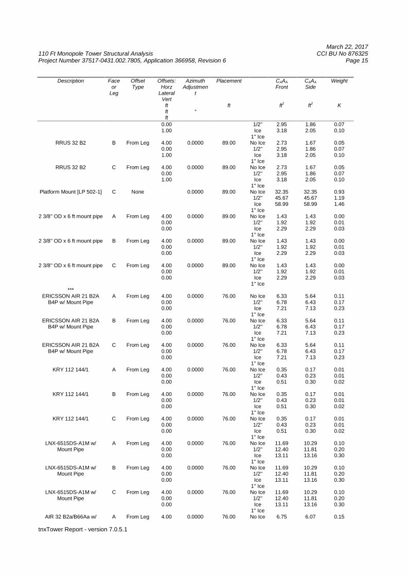
RRUS 32 B2 A From Leg 4.00 0.0000 89.00 No Ice 2.73 1.67 0.05
March 22, 2017110 Ft Monopole Tower Structural Analysis CCI BU No 876325Project Number 37517-0431.002.7805, Application 366958, Revision 6 Page 15
tnxTower Report - version 7.0.5.1
Description Faceor
Leg
OffsetType
Offsets:Horz
LateralVert
ftftft
AzimuthAdjustmen
t
°
Placement
ft
CAAA
Front
ft2
CAAA
Side
ft2
Weight
K
0.001.00
1/2''Ice
1'' Ice
2.953.18
1.862.05
0.070.10
RRUS 32 B2 B From Leg 4.000.001.00
0.0000 89.00 No Ice1/2''Ice
1'' Ice
2.732.953.18
1.671.862.05
0.050.070.10
RRUS 32 B2 C From Leg 4.000.001.00
0.0000 89.00 No Ice1/2''Ice
1'' Ice
2.732.953.18
1.671.862.05
0.050.070.10
Platform Mount [LP 502-1] C None 0.0000 89.00 No Ice1/2''Ice
1'' Ice
32.3545.6758.99
32.3545.6758.99
0.931.191.46
2 3/8'' OD x 6 ft mount pipe A From Leg 4.000.000.00
0.0000 89.00 No Ice1/2''Ice
1'' Ice
1.431.922.29
1.431.922.29
0.000.010.03
2 3/8'' OD x 6 ft mount pipe B From Leg 4.000.000.00
0.0000 89.00 No Ice1/2''Ice
1'' Ice
1.431.922.29
1.431.922.29
0.000.010.03
2 3/8'' OD x 6 ft mount pipe C From Leg 4.000.000.00
0.0000 89.00 No Ice1/2''Ice
1'' Ice
1.431.922.29
1.431.922.29
0.000.010.03
***ERICSSON AIR 21 B2A
B4P w/ Mount PipeA From Leg 4.00
0.000.00
0.0000 76.00 No Ice1/2''Ice
1'' Ice
6.336.787.21
5.646.437.13
0.110.170.23
ERICSSON AIR 21 B2AB4P w/ Mount Pipe
B From Leg 4.000.000.00
0.0000 76.00 No Ice1/2''Ice
1'' Ice
6.336.787.21
5.646.437.13
0.110.170.23
ERICSSON AIR 21 B2AB4P w/ Mount Pipe
C From Leg 4.000.000.00
0.0000 76.00 No Ice1/2''Ice
1'' Ice
6.336.787.21
5.646.437.13
0.110.170.23
KRY 112 144/1 A From Leg 4.000.000.00
0.0000 76.00 No Ice1/2''Ice
1'' Ice
0.350.430.51
0.170.230.30
0.010.010.02
KRY 112 144/1 B From Leg 4.000.000.00
0.0000 76.00 No Ice1/2''Ice
1'' Ice
0.350.430.51
0.170.230.30
0.010.010.02
KRY 112 144/1 C From Leg 4.000.000.00
0.0000 76.00 No Ice1/2''Ice
1'' Ice
0.350.430.51
0.170.230.30
0.010.010.02
LNX-6515DS-A1M w/Mount Pipe
A From Leg 4.000.000.00
0.0000 76.00 No Ice1/2''Ice
1'' Ice
11.6912.4013.11
10.2911.8113.16
0.100.200.30
LNX-6515DS-A1M w/Mount Pipe
B From Leg 4.000.000.00
0.0000 76.00 No Ice1/2''Ice
1'' Ice
11.6912.4013.11
10.2911.8113.16
0.100.200.30
LNX-6515DS-A1M w/Mount Pipe
C From Leg 4.000.000.00
0.0000 76.00 No Ice1/2''Ice
1'' Ice
11.6912.4013.11
10.2911.8113.16
0.100.200.30
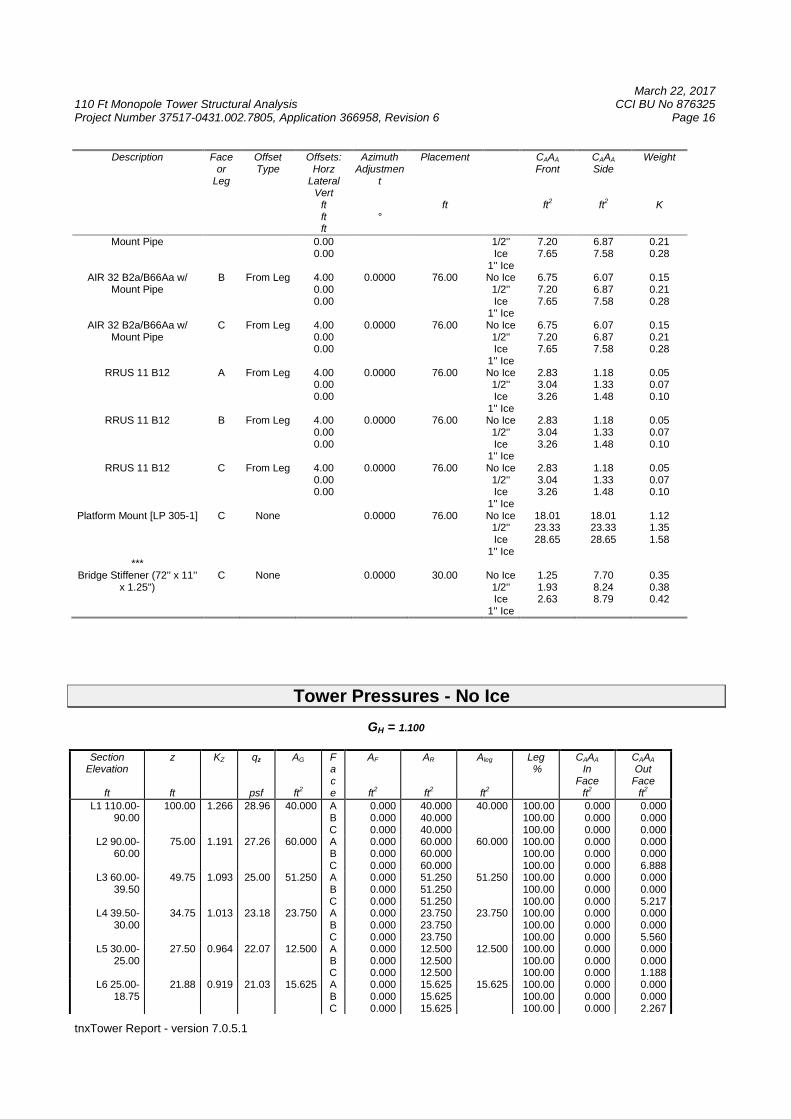
AIR 32 B2a/B66Aa w/ A From Leg 4.00 0.0000 76.00 No Ice 6.75 6.07 0.15
March 22, 2017110 Ft Monopole Tower Structural Analysis CCI BU No 876325Project Number 37517-0431.002.7805, Application 366958, Revision 6 Page 16
tnxTower Report - version 7.0.5.1
Description Faceor
Leg
OffsetType
Offsets:Horz
LateralVert
ftftft
AzimuthAdjustmen
t
°
Placement
ft
CAAA
Front
ft2
CAAA
Side
ft2
Weight
K
Mount Pipe 0.000.00
1/2''Ice
1'' Ice
7.207.65
6.877.58
0.210.28
AIR 32 B2a/B66Aa w/Mount Pipe
B From Leg 4.000.000.00
0.0000 76.00 No Ice1/2''Ice
1'' Ice
6.757.207.65
6.076.877.58
0.150.210.28
AIR 32 B2a/B66Aa w/Mount Pipe
C From Leg 4.000.000.00
0.0000 76.00 No Ice1/2''Ice
1'' Ice
6.757.207.65
6.076.877.58
0.150.210.28
RRUS 11 B12 A From Leg 4.000.000.00
0.0000 76.00 No Ice1/2''Ice
1'' Ice
2.833.043.26
1.181.331.48
0.050.070.10
RRUS 11 B12 B From Leg 4.000.000.00
0.0000 76.00 No Ice1/2''Ice
1'' Ice
2.833.043.26
1.181.331.48
0.050.070.10
RRUS 11 B12 C From Leg 4.000.000.00
0.0000 76.00 No Ice1/2''Ice
1'' Ice
2.833.043.26
1.181.331.48
0.050.070.10
Platform Mount [LP 305-1] C None 0.0000 76.00 No Ice1/2''Ice
1'' Ice
18.0123.3328.65
18.0123.3328.65
1.121.351.58
***Bridge Stiffener (72'' x 11''
x 1.25'')C None 0.0000 30.00 No Ice
1/2''Ice
1'' Ice
1.251.932.63
7.708.248.79
0.350.380.42
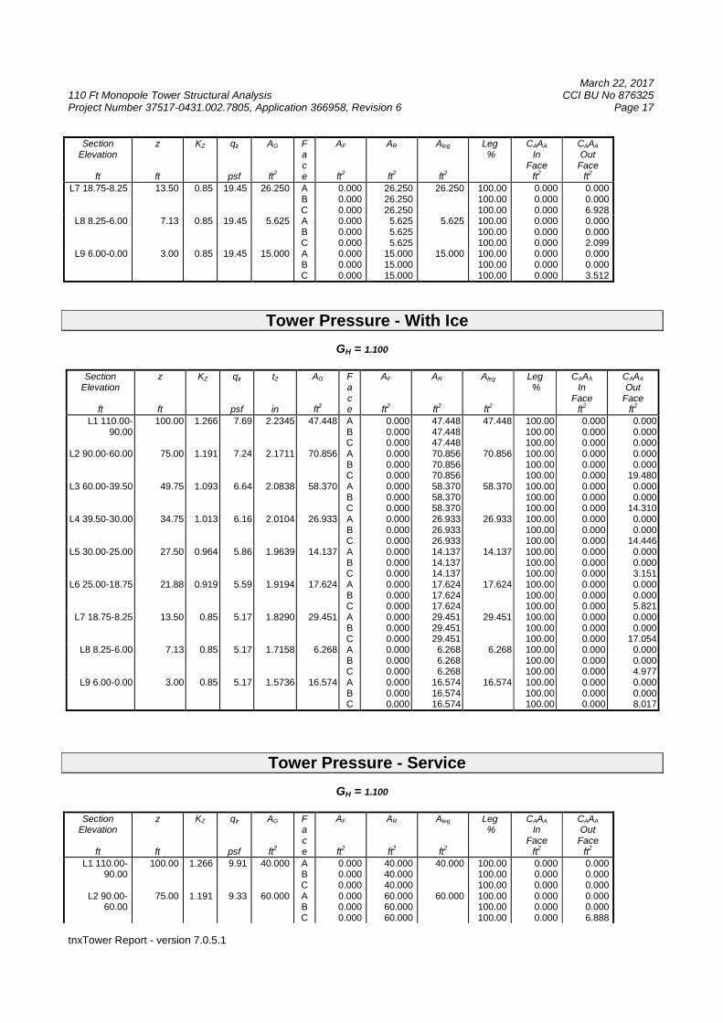
Tower Pressures - No Ice
GH = 1.100
SectionElevation
ft
z
ft
KZ qz
psf
AG
ft2
Face
AF
ft2
AR
ft2
Aleg
ft2
Leg%
CAAA
InFace
ft2
CAAA
OutFace
ft2
L1 110.00-90.00
100.00 1.266 28.96 40.000 ABC
0.0000.0000.000
40.00040.00040.000
40.000 100.00100.00100.00
0.0000.0000.000
0.0000.0000.000
L2 90.00-60.00
75.00 1.191 27.26 60.000 ABC
0.0000.0000.000
60.00060.00060.000
60.000 100.00100.00100.00
0.0000.0000.000
0.0000.0006.888
L3 60.00-39.50
49.75 1.093 25.00 51.250 ABC
0.0000.0000.000
51.25051.25051.250
51.250 100.00100.00100.00
0.0000.0000.000
0.0000.0005.217
L4 39.50-30.00
34.75 1.013 23.18 23.750 ABC
0.0000.0000.000
23.75023.75023.750
23.750 100.00100.00100.00
0.0000.0000.000
0.0000.0005.560
L5 30.00-25.00
27.50 0.964 22.07 12.500 ABC
0.0000.0000.000
12.50012.50012.500
12.500 100.00100.00100.00
0.0000.0000.000
0.0000.0001.188
L6 25.00-18.75
21.88 0.919 21.03 15.625 ABC
0.0000.0000.000
15.62515.62515.625
15.625 100.00100.00100.00
0.0000.0000.000
0.0000.0002.267
March 22, 2017110 Ft Monopole Tower Structural Analysis CCI BU No 876325Project Number 37517-0431.002.7805, Application 366958, Revision 6 Page 17
tnxTower Report - version 7.0.5.1
SectionElevation
ft
z
ft
KZ qz
psf
AG
ft2
Face
AF
ft2
AR
ft2
Aleg
ft2
Leg%
CAAA
InFace
ft2
CAAA
OutFace
ft2
L7 18.75-8.25 13.50 0.85 19.45 26.250 ABC
0.0000.0000.000
26.25026.25026.250
26.250 100.00100.00100.00
0.0000.0000.000
0.0000.0006.928
L8 8.25-6.00 7.13 0.85 19.45 5.625 ABC
0.0000.0000.000
5.6255.6255.625
5.625 100.00100.00100.00
0.0000.0000.000
0.0000.0002.099
L9 6.00-0.00 3.00 0.85 19.45 15.000 ABC
0.0000.0000.000
15.00015.00015.000
15.000 100.00100.00100.00
0.0000.0000.000
0.0000.0003.512
Tower Pressure - With Ice
GH = 1.100
SectionElevation
ft
z
ft
KZ qz
psf
tZ
in
AG
ft2
Face
AF
ft2
AR
ft2
Aleg
ft2
Leg%
CAAA
InFace
ft2
CAAA
OutFace
ft2
L1 110.00-90.00
100.00 1.266 7.69 2.2345 47.448 ABC
0.0000.0000.000
47.44847.44847.448
47.448 100.00100.00100.00
0.0000.0000.000
0.0000.0000.000
L2 90.00-60.00 75.00 1.191 7.24 2.1711 70.856 ABC
0.0000.0000.000
70.85670.85670.856
70.856 100.00100.00100.00
0.0000.0000.000
0.0000.000
19.480L3 60.00-39.50 49.75 1.093 6.64 2.0838 58.370 A
BC
0.0000.0000.000
58.37058.37058.370
58.370 100.00100.00100.00
0.0000.0000.000
0.0000.000
14.310L4 39.50-30.00 34.75 1.013 6.16 2.0104 26.933 A
BC
0.0000.0000.000
26.93326.93326.933
26.933 100.00100.00100.00
0.0000.0000.000
0.0000.000
14.446L5 30.00-25.00 27.50 0.964 5.86 1.9639 14.137 A
BC
0.0000.0000.000
14.13714.13714.137
14.137 100.00100.00100.00
0.0000.0000.000
0.0000.0003.151
L6 25.00-18.75 21.88 0.919 5.59 1.9194 17.624 ABC
0.0000.0000.000
17.62417.62417.624
17.624 100.00100.00100.00
0.0000.0000.000
0.0000.0005.821
L7 18.75-8.25 13.50 0.85 5.17 1.8290 29.451 ABC
0.0000.0000.000
29.45129.45129.451
29.451 100.00100.00100.00
0.0000.0000.000
0.0000.000
17.054L8 8.25-6.00 7.13 0.85 5.17 1.7158 6.268 A
BC
0.0000.0000.000
6.2686.2686.268
6.268 100.00100.00100.00
0.0000.0000.000
0.0000.0004.977
L9 6.00-0.00 3.00 0.85 5.17 1.5736 16.574 ABC
0.0000.0000.000
16.57416.57416.574
16.574 100.00100.00100.00
0.0000.0000.000
0.0000.0008.017
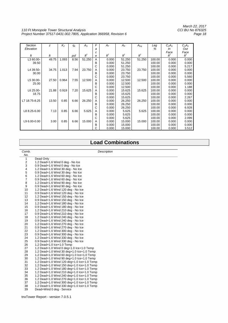
Tower Pressure - Service
GH = 1.100
SectionElevation
ft
z
ft
KZ qz
psf
AG
ft2
Face
AF
ft2
AR
ft2
Aleg
ft2
Leg%
CAAA
InFace
ft2
CAAA
OutFace
ft2
L1 110.00-90.00
100.00 1.266 9.91 40.000 ABC
0.0000.0000.000
40.00040.00040.000
40.000 100.00100.00100.00
0.0000.0000.000
0.0000.0000.000
L2 90.00-60.00
75.00 1.191 9.33 60.000 ABC
0.0000.0000.000
60.00060.00060.000
60.000 100.00100.00100.00
0.0000.0000.000
0.0000.0006.888
March 22, 2017110 Ft Monopole Tower Structural Analysis CCI BU No 876325Project Number 37517-0431.002.7805, Application 366958, Revision 6 Page 18
tnxTower Report - version 7.0.5.1
SectionElevation
ft
z
ft
KZ qz
psf
AG
ft2
Face
AF
ft2
AR
ft2
Aleg
ft2
Leg%
CAAA
InFace
ft2
CAAA
OutFace
ft2
L3 60.00-39.50
49.75 1.093 8.56 51.250 ABC
0.0000.0000.000
51.25051.25051.250
51.250 100.00100.00100.00
0.0000.0000.000
0.0000.0005.217
L4 39.50-30.00
34.75 1.013 7.94 23.750 ABC
0.0000.0000.000
23.75023.75023.750
23.750 100.00100.00100.00
0.0000.0000.000
0.0000.0005.560
L5 30.00-25.00
27.50 0.964 7.55 12.500 ABC
0.0000.0000.000
12.50012.50012.500
12.500 100.00100.00100.00
0.0000.0000.000
0.0000.0001.188
L6 25.00-18.75
21.88 0.919 7.20 15.625 ABC
0.0000.0000.000
15.62515.62515.625
15.625 100.00100.00100.00
0.0000.0000.000
0.0000.0002.267
L7 18.75-8.25 13.50 0.85 6.66 26.250 ABC
0.0000.0000.000
26.25026.25026.250
26.250 100.00100.00100.00
0.0000.0000.000
0.0000.0006.928
L8 8.25-6.00 7.13 0.85 6.66 5.625 ABC
0.0000.0000.000
5.6255.6255.625
5.625 100.00100.00100.00
0.0000.0000.000
0.0000.0002.099
L9 6.00-0.00 3.00 0.85 6.66 15.000 ABC
0.0000.0000.000
15.00015.00015.000
15.000 100.00100.00100.00
0.0000.0000.000
0.0000.0003.512
Load Combinations
Comb.No.
Description
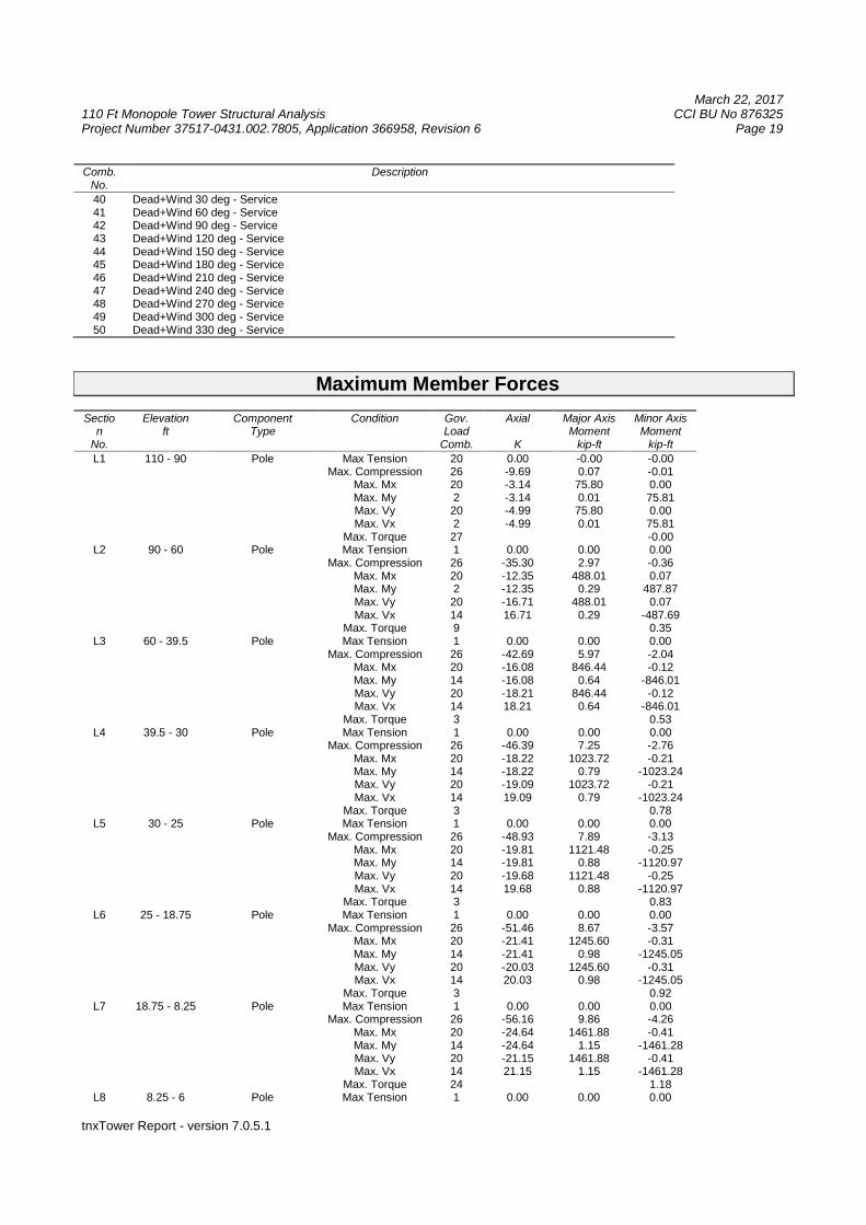
1 Dead Only2 1.2 Dead+1.6 Wind 0 deg - No Ice3 0.9 Dead+1.6 Wind 0 deg - No Ice4 1.2 Dead+1.6 Wind 30 deg - No Ice5 0.9 Dead+1.6 Wind 30 deg - No Ice6 1.2 Dead+1.6 Wind 60 deg - No Ice7 0.9 Dead+1.6 Wind 60 deg - No Ice8 1.2 Dead+1.6 Wind 90 deg - No Ice9 0.9 Dead+1.6 Wind 90 deg - No Ice10 1.2 Dead+1.6 Wind 120 deg - No Ice11 0.9 Dead+1.6 Wind 120 deg - No Ice12 1.2 Dead+1.6 Wind 150 deg - No Ice13 0.9 Dead+1.6 Wind 150 deg - No Ice14 1.2 Dead+1.6 Wind 180 deg - No Ice15 0.9 Dead+1.6 Wind 180 deg - No Ice16 1.2 Dead+1.6 Wind 210 deg - No Ice17 0.9 Dead+1.6 Wind 210 deg - No Ice18 1.2 Dead+1.6 Wind 240 deg - No Ice19 0.9 Dead+1.6 Wind 240 deg - No Ice20 1.2 Dead+1.6 Wind 270 deg - No Ice21 0.9 Dead+1.6 Wind 270 deg - No Ice22 1.2 Dead+1.6 Wind 300 deg - No Ice23 0.9 Dead+1.6 Wind 300 deg - No Ice24 1.2 Dead+1.6 Wind 330 deg - No Ice25 0.9 Dead+1.6 Wind 330 deg - No Ice26 1.2 Dead+1.0 Ice+1.0 Temp27 1.2 Dead+1.0 Wind 0 deg+1.0 Ice+1.0 Temp28 1.2 Dead+1.0 Wind 30 deg+1.0 Ice+1.0 Temp29 1.2 Dead+1.0 Wind 60 deg+1.0 Ice+1.0 Temp30 1.2 Dead+1.0 Wind 90 deg+1.0 Ice+1.0 Temp31 1.2 Dead+1.0 Wind 120 deg+1.0 Ice+1.0 Temp32 1.2 Dead+1.0 Wind 150 deg+1.0 Ice+1.0 Temp33 1.2 Dead+1.0 Wind 180 deg+1.0 Ice+1.0 Temp34 1.2 Dead+1.0 Wind 210 deg+1.0 Ice+1.0 Temp35 1.2 Dead+1.0 Wind 240 deg+1.0 Ice+1.0 Temp36 1.2 Dead+1.0 Wind 270 deg+1.0 Ice+1.0 Temp37 1.2 Dead+1.0 Wind 300 deg+1.0 Ice+1.0 Temp38 1.2 Dead+1.0 Wind 330 deg+1.0 Ice+1.0 Temp39 Dead+Wind 0 deg - Service
March 22, 2017110 Ft Monopole Tower Structural Analysis CCI BU No 876325Project Number 37517-0431.002.7805, Application 366958, Revision 6 Page 19
tnxTower Report - version 7.0.5.1
Comb.No.
Description
40 Dead+Wind 30 deg - Service41 Dead+Wind 60 deg - Service42 Dead+Wind 90 deg - Service43 Dead+Wind 120 deg - Service44 Dead+Wind 150 deg - Service45 Dead+Wind 180 deg - Service46 Dead+Wind 210 deg - Service47 Dead+Wind 240 deg - Service48 Dead+Wind 270 deg - Service49 Dead+Wind 300 deg - Service50 Dead+Wind 330 deg - Service
Maximum Member Forces
Section
No.
Elevationft
ComponentType
Condition Gov.Load
Comb.
Axial
K
Major AxisMoment
kip-ft
Minor AxisMoment
kip-ft
L1 110 - 90 Pole Max Tension 20 0.00 -0.00 -0.00Max. Compression 26 -9.69 0.07 -0.01
Max. Mx 20 -3.14 75.80 0.00Max. My 2 -3.14 0.01 75.81Max. Vy 20 -4.99 75.80 0.00Max. Vx 2 -4.99 0.01 75.81
Max. Torque 27 -0.00L2 90 - 60 Pole Max Tension 1 0.00 0.00 0.00
Max. Compression 26 -35.30 2.97 -0.36Max. Mx 20 -12.35 488.01 0.07Max. My 2 -12.35 0.29 487.87Max. Vy 20 -16.71 488.01 0.07Max. Vx 14 16.71 0.29 -487.69
Max. Torque 9 0.35L3 60 - 39.5 Pole Max Tension 1 0.00 0.00 0.00
Max. Compression 26 -42.69 5.97 -2.04Max. Mx 20 -16.08 846.44 -0.12Max. My 14 -16.08 0.64 -846.01Max. Vy 20 -18.21 846.44 -0.12Max. Vx 14 18.21 0.64 -846.01
Max. Torque 3 0.53L4 39.5 - 30 Pole Max Tension 1 0.00 0.00 0.00
Max. Compression 26 -46.39 7.25 -2.76Max. Mx 20 -18.22 1023.72 -0.21Max. My 14 -18.22 0.79 -1023.24Max. Vy 20 -19.09 1023.72 -0.21Max. Vx 14 19.09 0.79 -1023.24
Max. Torque 3 0.78L5 30 - 25 Pole Max Tension 1 0.00 0.00 0.00
Max. Compression 26 -48.93 7.89 -3.13Max. Mx 20 -19.81 1121.48 -0.25Max. My 14 -19.81 0.88 -1120.97Max. Vy 20 -19.68 1121.48 -0.25Max. Vx 14 19.68 0.88 -1120.97
Max. Torque 3 0.83L6 25 - 18.75 Pole Max Tension 1 0.00 0.00 0.00
Max. Compression 26 -51.46 8.67 -3.57Max. Mx 20 -21.41 1245.60 -0.31Max. My 14 -21.41 0.98 -1245.05Max. Vy 20 -20.03 1245.60 -0.31Max. Vx 14 20.03 0.98 -1245.05
Max. Torque 3 0.92L7 18.75 - 8.25 Pole Max Tension 1 0.00 0.00 0.00
Max. Compression 26 -56.16 9.86 -4.26Max. Mx 20 -24.64 1461.88 -0.41Max. My 14 -24.64 1.15 -1461.28Max. Vy 20 -21.15 1461.88 -0.41Max. Vx 14 21.15 1.15 -1461.28
Max. Torque 24 1.18L8 8.25 - 6 Pole Max Tension 1 0.00 0.00 0.00
March 22, 2017110 Ft Monopole Tower Structural Analysis CCI BU No 876325Project Number 37517-0431.002.7805, Application 366958, Revision 6 Page 20
tnxTower Report - version 7.0.5.1
Section
No.
Elevationft
ComponentType
Condition Gov.Load
Comb.
Axial
K
Major AxisMoment
kip-ft
Minor AxisMoment
kip-ft
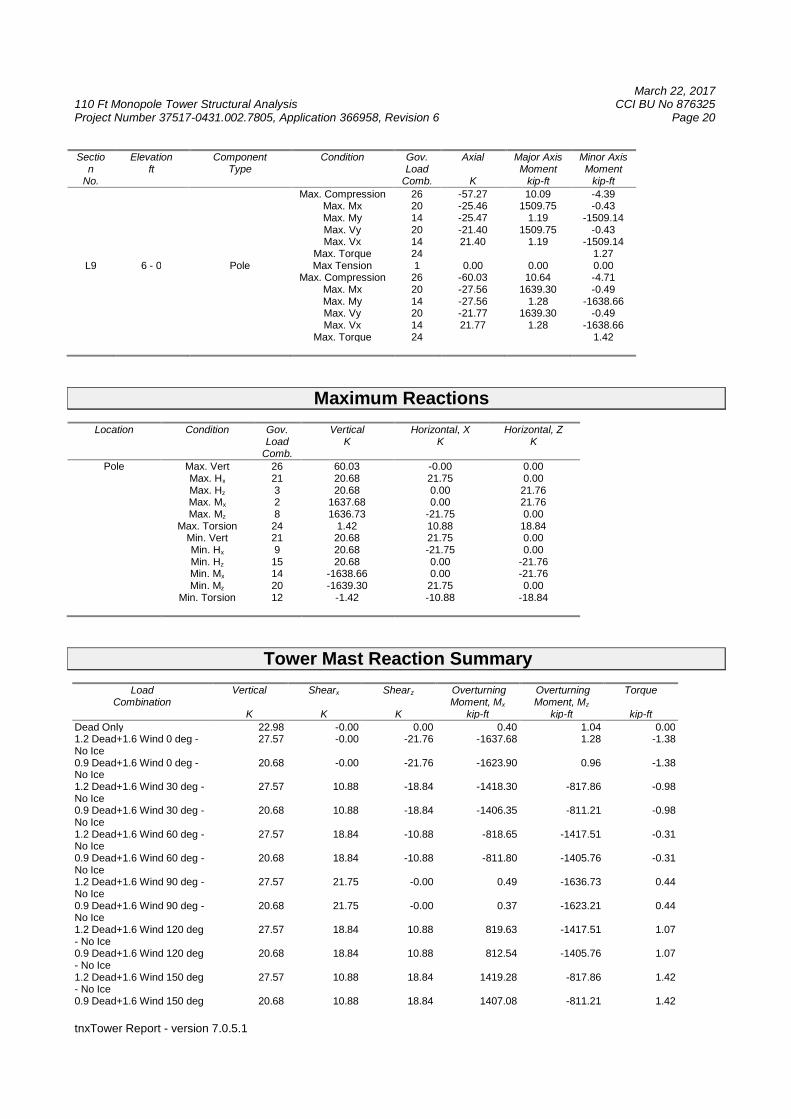
Max. Compression 26 -57.27 10.09 -4.39Max. Mx 20 -25.46 1509.75 -0.43Max. My 14 -25.47 1.19 -1509.14Max. Vy 20 -21.40 1509.75 -0.43Max. Vx 14 21.40 1.19 -1509.14
Max. Torque 24 1.27L9 6 - 0 Pole Max Tension 1 0.00 0.00 0.00
Max. Compression 26 -60.03 10.64 -4.71Max. Mx 20 -27.56 1639.30 -0.49Max. My 14 -27.56 1.28 -1638.66Max. Vy 20 -21.77 1639.30 -0.49Max. Vx 14 21.77 1.28 -1638.66
Max. Torque 24 1.42
Maximum Reactions
Location Condition Gov.Load
Comb.
VerticalK
Horizontal, XK
Horizontal, ZK
Pole Max. Vert 26 60.03 -0.00 0.00Max. Hx 21 20.68 21.75 0.00Max. Hz 3 20.68 0.00 21.76Max. Mx 2 1637.68 0.00 21.76Max. Mz 8 1636.73 -21.75 0.00
Max. Torsion 24 1.42 10.88 18.84Min. Vert 21 20.68 21.75 0.00Min. Hx 9 20.68 -21.75 0.00Min. Hz 15 20.68 0.00 -21.76Min. Mx 14 -1638.66 0.00 -21.76Min. Mz 20 -1639.30 21.75 0.00
Min. Torsion 12 -1.42 -10.88 -18.84
Tower Mast Reaction Summary
LoadCombination
Vertical
K
Shearx
K
Shearz
K
OverturningMoment, Mx
kip-ft
OverturningMoment, Mz
kip-ft
Torque
kip-ft
Dead Only 22.98 -0.00 0.00 0.40 1.04 0.001.2 Dead+1.6 Wind 0 deg -No Ice
27.57 -0.00 -21.76 -1637.68 1.28 -1.38
0.9 Dead+1.6 Wind 0 deg -No Ice
20.68 -0.00 -21.76 -1623.90 0.96 -1.38
1.2 Dead+1.6 Wind 30 deg -No Ice
27.57 10.88 -18.84 -1418.30 -817.86 -0.98
0.9 Dead+1.6 Wind 30 deg -No Ice
20.68 10.88 -18.84 -1406.35 -811.21 -0.98
1.2 Dead+1.6 Wind 60 deg -No Ice
27.57 18.84 -10.88 -818.65 -1417.51 -0.31
0.9 Dead+1.6 Wind 60 deg -No Ice
20.68 18.84 -10.88 -811.80 -1405.76 -0.31
1.2 Dead+1.6 Wind 90 deg -No Ice
27.57 21.75 -0.00 0.49 -1636.73 0.44
0.9 Dead+1.6 Wind 90 deg -No Ice
20.68 21.75 -0.00 0.37 -1623.21 0.44
1.2 Dead+1.6 Wind 120 deg- No Ice
27.57 18.84 10.88 819.63 -1417.51 1.07
0.9 Dead+1.6 Wind 120 deg- No Ice
20.68 18.84 10.88 812.54 -1405.76 1.07
1.2 Dead+1.6 Wind 150 deg- No Ice
27.57 10.88 18.84 1419.28 -817.86 1.42
0.9 Dead+1.6 Wind 150 deg 20.68 10.88 18.84 1407.08 -811.21 1.42
March 22, 2017110 Ft Monopole Tower Structural Analysis CCI BU No 876325Project Number 37517-0431.002.7805, Application 366958, Revision 6 Page 21
tnxTower Report - version 7.0.5.1
LoadCombination
Vertical
K
Shearx
K
Shearz
K
OverturningMoment, Mx
kip-ft
OverturningMoment, Mz
kip-ft
Torque
kip-ft
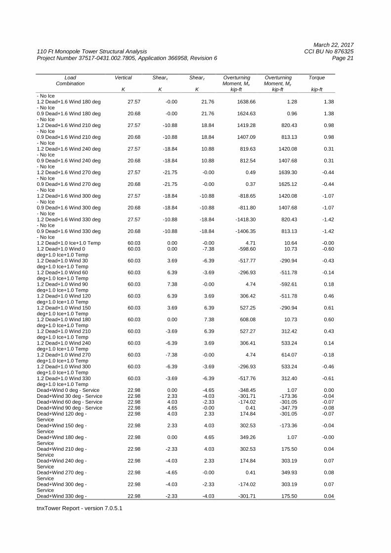
- No Ice1.2 Dead+1.6 Wind 180 deg- No Ice
27.57 -0.00 21.76 1638.66 1.28 1.38
0.9 Dead+1.6 Wind 180 deg- No Ice
20.68 -0.00 21.76 1624.63 0.96 1.38
1.2 Dead+1.6 Wind 210 deg- No Ice
27.57 -10.88 18.84 1419.28 820.43 0.98
0.9 Dead+1.6 Wind 210 deg- No Ice
20.68 -10.88 18.84 1407.09 813.13 0.98
1.2 Dead+1.6 Wind 240 deg- No Ice
27.57 -18.84 10.88 819.63 1420.08 0.31
0.9 Dead+1.6 Wind 240 deg- No Ice
20.68 -18.84 10.88 812.54 1407.68 0.31
1.2 Dead+1.6 Wind 270 deg- No Ice
27.57 -21.75 -0.00 0.49 1639.30 -0.44
0.9 Dead+1.6 Wind 270 deg- No Ice
20.68 -21.75 -0.00 0.37 1625.12 -0.44
1.2 Dead+1.6 Wind 300 deg- No Ice
27.57 -18.84 -10.88 -818.65 1420.08 -1.07
0.9 Dead+1.6 Wind 300 deg- No Ice
20.68 -18.84 -10.88 -811.80 1407.68 -1.07
1.2 Dead+1.6 Wind 330 deg- No Ice
27.57 -10.88 -18.84 -1418.30 820.43 -1.42
0.9 Dead+1.6 Wind 330 deg- No Ice
20.68 -10.88 -18.84 -1406.35 813.13 -1.42
1.2 Dead+1.0 Ice+1.0 Temp 60.03 0.00 -0.00 4.71 10.64 -0.001.2 Dead+1.0 Wind 0deg+1.0 Ice+1.0 Temp
60.03 0.00 -7.38 -598.60 10.73 -0.60
1.2 Dead+1.0 Wind 30deg+1.0 Ice+1.0 Temp
60.03 3.69 -6.39 -517.77 -290.94 -0.43
1.2 Dead+1.0 Wind 60deg+1.0 Ice+1.0 Temp
60.03 6.39 -3.69 -296.93 -511.78 -0.14
1.2 Dead+1.0 Wind 90deg+1.0 Ice+1.0 Temp
60.03 7.38 -0.00 4.74 -592.61 0.18
1.2 Dead+1.0 Wind 120deg+1.0 Ice+1.0 Temp
60.03 6.39 3.69 306.42 -511.78 0.46
1.2 Dead+1.0 Wind 150deg+1.0 Ice+1.0 Temp
60.03 3.69 6.39 527.25 -290.94 0.61
1.2 Dead+1.0 Wind 180deg+1.0 Ice+1.0 Temp
60.03 0.00 7.38 608.08 10.73 0.60
1.2 Dead+1.0 Wind 210deg+1.0 Ice+1.0 Temp
60.03 -3.69 6.39 527.27 312.42 0.43
1.2 Dead+1.0 Wind 240deg+1.0 Ice+1.0 Temp
60.03 -6.39 3.69 306.41 533.24 0.14
1.2 Dead+1.0 Wind 270deg+1.0 Ice+1.0 Temp
60.03 -7.38 -0.00 4.74 614.07 -0.18
1.2 Dead+1.0 Wind 300deg+1.0 Ice+1.0 Temp
60.03 -6.39 -3.69 -296.93 533.24 -0.46
1.2 Dead+1.0 Wind 330deg+1.0 Ice+1.0 Temp
60.03 -3.69 -6.39 -517.76 312.40 -0.61
Dead+Wind 0 deg - Service 22.98 0.00 -4.65 -348.45 1.07 0.00Dead+Wind 30 deg - Service 22.98 2.33 -4.03 -301.71 -173.36 -0.04Dead+Wind 60 deg - Service 22.98 4.03 -2.33 -174.02 -301.05 -0.07Dead+Wind 90 deg - Service 22.98 4.65 -0.00 0.41 -347.79 -0.08Dead+Wind 120 deg -Service
22.98 4.03 2.33 174.84 -301.05 -0.07
Dead+Wind 150 deg -Service
22.98 2.33 4.03 302.53 -173.36 -0.04
Dead+Wind 180 deg -Service
22.98 0.00 4.65 349.26 1.07 -0.00
Dead+Wind 210 deg -Service
22.98 -2.33 4.03 302.53 175.50 0.04
Dead+Wind 240 deg -Service
22.98 -4.03 2.33 174.84 303.19 0.07
Dead+Wind 270 deg -Service
22.98 -4.65 -0.00 0.41 349.93 0.08
Dead+Wind 300 deg -Service
22.98 -4.03 -2.33 -174.02 303.19 0.07
Dead+Wind 330 deg - 22.98 -2.33 -4.03 -301.71 175.50 0.04
March 22, 2017110 Ft Monopole Tower Structural Analysis CCI BU No 876325Project Number 37517-0431.002.7805, Application 366958, Revision 6 Page 22
tnxTower Report - version 7.0.5.1
LoadCombination
Vertical
K
Shearx
K
Shearz
K
OverturningMoment, Mx
kip-ft
OverturningMoment, Mz
kip-ft
Torque
kip-ft
Service
Solution Summary
LoadComb.
Sum of Applied Forces Sum of Reactions% ErrorPX
KPYK
PZK
PXK
PYK
PZK
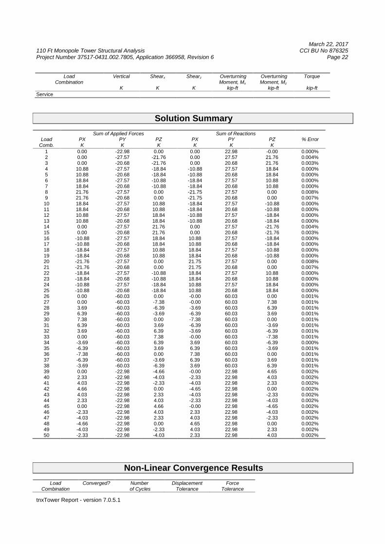
1 0.00 -22.98 0.00 0.00 22.98 -0.00 0.000%2 0.00 -27.57 -21.76 0.00 27.57 21.76 0.004%3 0.00 -20.68 -21.76 0.00 20.68 21.76 0.003%4 10.88 -27.57 -18.84 -10.88 27.57 18.84 0.000%5 10.88 -20.68 -18.84 -10.88 20.68 18.84 0.000%6 18.84 -27.57 -10.88 -18.84 27.57 10.88 0.000%7 18.84 -20.68 -10.88 -18.84 20.68 10.88 0.000%8 21.76 -27.57 0.00 -21.75 27.57 0.00 0.008%9 21.76 -20.68 0.00 -21.75 20.68 0.00 0.007%10 18.84 -27.57 10.88 -18.84 27.57 -10.88 0.000%11 18.84 -20.68 10.88 -18.84 20.68 -10.88 0.000%12 10.88 -27.57 18.84 -10.88 27.57 -18.84 0.000%13 10.88 -20.68 18.84 -10.88 20.68 -18.84 0.000%14 0.00 -27.57 21.76 0.00 27.57 -21.76 0.004%15 0.00 -20.68 21.76 0.00 20.68 -21.76 0.003%16 -10.88 -27.57 18.84 10.88 27.57 -18.84 0.000%17 -10.88 -20.68 18.84 10.88 20.68 -18.84 0.000%18 -18.84 -27.57 10.88 18.84 27.57 -10.88 0.000%19 -18.84 -20.68 10.88 18.84 20.68 -10.88 0.000%20 -21.76 -27.57 0.00 21.75 27.57 0.00 0.008%21 -21.76 -20.68 0.00 21.75 20.68 0.00 0.007%22 -18.84 -27.57 -10.88 18.84 27.57 10.88 0.000%23 -18.84 -20.68 -10.88 18.84 20.68 10.88 0.000%24 -10.88 -27.57 -18.84 10.88 27.57 18.84 0.000%25 -10.88 -20.68 -18.84 10.88 20.68 18.84 0.000%26 0.00 -60.03 0.00 -0.00 60.03 0.00 0.001%27 0.00 -60.03 -7.38 -0.00 60.03 7.38 0.001%28 3.69 -60.03 -6.39 -3.69 60.03 6.39 0.001%29 6.39 -60.03 -3.69 -6.39 60.03 3.69 0.001%30 7.38 -60.03 0.00 -7.38 60.03 0.00 0.001%31 6.39 -60.03 3.69 -6.39 60.03 -3.69 0.001%32 3.69 -60.03 6.39 -3.69 60.03 -6.39 0.001%33 0.00 -60.03 7.38 -0.00 60.03 -7.38 0.001%34 -3.69 -60.03 6.39 3.69 60.03 -6.39 0.000%35 -6.39 -60.03 3.69 6.39 60.03 -3.69 0.001%36 -7.38 -60.03 0.00 7.38 60.03 0.00 0.001%37 -6.39 -60.03 -3.69 6.39 60.03 3.69 0.001%38 -3.69 -60.03 -6.39 3.69 60.03 6.39 0.001%39 0.00 -22.98 -4.66 -0.00 22.98 4.65 0.002%40 2.33 -22.98 -4.03 -2.33 22.98 4.03 0.002%41 4.03 -22.98 -2.33 -4.03 22.98 2.33 0.002%42 4.66 -22.98 0.00 -4.65 22.98 0.00 0.002%43 4.03 -22.98 2.33 -4.03 22.98 -2.33 0.002%44 2.33 -22.98 4.03 -2.33 22.98 -4.03 0.002%45 0.00 -22.98 4.66 -0.00 22.98 -4.65 0.002%46 -2.33 -22.98 4.03 2.33 22.98 -4.03 0.002%47 -4.03 -22.98 2.33 4.03 22.98 -2.33 0.002%48 -4.66 -22.98 0.00 4.65 22.98 0.00 0.002%49 -4.03 -22.98 -2.33 4.03 22.98 2.33 0.002%50 -2.33 -22.98 -4.03 2.33 22.98 4.03 0.002%
Non-Linear Convergence Results
LoadCombination
Converged? Numberof Cycles
DisplacementTolerance
ForceTolerance
March 22, 2017110 Ft Monopole Tower Structural Analysis CCI BU No 876325Project Number 37517-0431.002.7805, Application 366958, Revision 6 Page 23
tnxTower Report - version 7.0.5.1
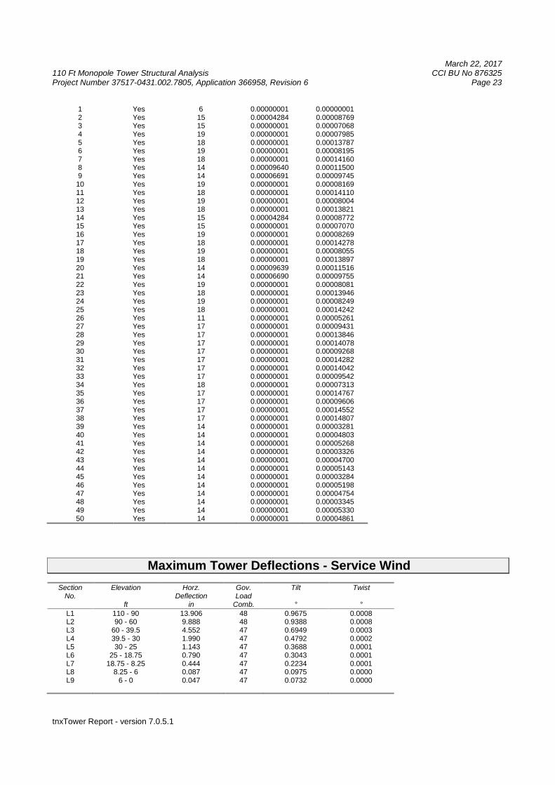
1 Yes 6 0.00000001 0.000000012 Yes 15 0.00004284 0.000087693 Yes 15 0.00000001 0.000070684 Yes 19 0.00000001 0.000079855 Yes 18 0.00000001 0.000137876 Yes 19 0.00000001 0.000081957 Yes 18 0.00000001 0.000141608 Yes 14 0.00009640 0.000115009 Yes 14 0.00006691 0.0000974510 Yes 19 0.00000001 0.0000816911 Yes 18 0.00000001 0.0001411012 Yes 19 0.00000001 0.0000800413 Yes 18 0.00000001 0.0001382114 Yes 15 0.00004284 0.0000877215 Yes 15 0.00000001 0.0000707016 Yes 19 0.00000001 0.0000826917 Yes 18 0.00000001 0.0001427818 Yes 19 0.00000001 0.0000805519 Yes 18 0.00000001 0.0001389720 Yes 14 0.00009639 0.0001151621 Yes 14 0.00006690 0.0000975522 Yes 19 0.00000001 0.0000808123 Yes 18 0.00000001 0.0001394624 Yes 19 0.00000001 0.0000824925 Yes 18 0.00000001 0.0001424226 Yes 11 0.00000001 0.0000526127 Yes 17 0.00000001 0.0000943128 Yes 17 0.00000001 0.0001384629 Yes 17 0.00000001 0.0001407830 Yes 17 0.00000001 0.0000926831 Yes 17 0.00000001 0.0001428232 Yes 17 0.00000001 0.0001404233 Yes 17 0.00000001 0.0000954234 Yes 18 0.00000001 0.0000731335 Yes 17 0.00000001 0.0001476736 Yes 17 0.00000001 0.0000960637 Yes 17 0.00000001 0.0001455238 Yes 17 0.00000001 0.0001480739 Yes 14 0.00000001 0.0000328140 Yes 14 0.00000001 0.0000480341 Yes 14 0.00000001 0.0000526842 Yes 14 0.00000001 0.0000332643 Yes 14 0.00000001 0.0000470044 Yes 14 0.00000001 0.0000514345 Yes 14 0.00000001 0.0000328446 Yes 14 0.00000001 0.0000519847 Yes 14 0.00000001 0.0000475448 Yes 14 0.00000001 0.0000334549 Yes 14 0.00000001 0.0000533050 Yes 14 0.00000001 0.00004861
Maximum Tower Deflections - Service Wind
SectionNo.
Elevation
ft
Horz.Deflection
in
Gov.Load
Comb.
Tilt
°
Twist
°L1 110 - 90 13.906 48 0.9675 0.0008L2 90 - 60 9.888 48 0.9388 0.0008L3 60 - 39.5 4.552 47 0.6949 0.0003L4 39.5 - 30 1.990 47 0.4792 0.0002L5 30 - 25 1.143 47 0.3688 0.0001L6 25 - 18.75 0.790 47 0.3043 0.0001L7 18.75 - 8.25 0.444 47 0.2234 0.0001L8 8.25 - 6 0.087 47 0.0975 0.0000L9 6 - 0 0.047 47 0.0732 0.0000
March 22, 2017110 Ft Monopole Tower Structural Analysis CCI BU No 876325Project Number 37517-0431.002.7805, Application 366958, Revision 6 Page 24
tnxTower Report - version 7.0.5.1
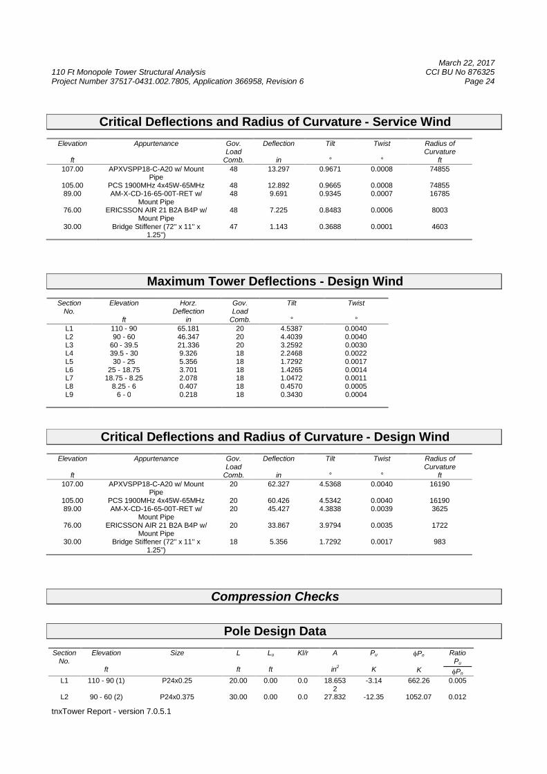
Critical Deflections and Radius of Curvature - Service Wind
Elevation
ft
Appurtenance Gov.Load
Comb.
Deflection
in
Tilt
°
Twist
°
Radius ofCurvature
ft
107.00 APXVSPP18-C-A20 w/ MountPipe
48 13.297 0.9671 0.0008 74855
105.00 PCS 1900MHz 4x45W-65MHz 48 12.892 0.9665 0.0008 7485589.00 AM-X-CD-16-65-00T-RET w/
Mount Pipe48 9.691 0.9345 0.0007 16785
76.00 ERICSSON AIR 21 B2A B4P w/Mount Pipe
48 7.225 0.8483 0.0006 8003
30.00 Bridge Stiffener (72'' x 11'' x1.25'')
47 1.143 0.3688 0.0001 4603
Maximum Tower Deflections - Design Wind
SectionNo.
Elevation
ft
Horz.Deflection
in
Gov.Load
Comb.
Tilt
°
Twist
°L1 110 - 90 65.181 20 4.5387 0.0040L2 90 - 60 46.347 20 4.4039 0.0040L3 60 - 39.5 21.336 20 3.2592 0.0030L4 39.5 - 30 9.326 18 2.2468 0.0022L5 30 - 25 5.356 18 1.7292 0.0017L6 25 - 18.75 3.701 18 1.4265 0.0014L7 18.75 - 8.25 2.078 18 1.0472 0.0011L8 8.25 - 6 0.407 18 0.4570 0.0005L9 6 - 0 0.218 18 0.3430 0.0004
Critical Deflections and Radius of Curvature - Design Wind
Elevation
ft
Appurtenance Gov.Load
Comb.
Deflection
in
Tilt
°
Twist
°
Radius ofCurvature
ft107.00 APXVSPP18-C-A20 w/ Mount
Pipe20 62.327 4.5368 0.0040 16190
105.00 PCS 1900MHz 4x45W-65MHz 20 60.426 4.5342 0.0040 1619089.00 AM-X-CD-16-65-00T-RET w/
Mount Pipe20 45.427 4.3838 0.0039 3625
76.00 ERICSSON AIR 21 B2A B4P w/Mount Pipe
20 33.867 3.9794 0.0035 1722
30.00 Bridge Stiffener (72'' x 11'' x1.25'')
18 5.356 1.7292 0.0017 983
Compression Checks
Pole Design Data
SectionNo.
Elevation
ft
Size L
ft
Lu
ft
Kl/r A
in2
Pu
K
Pn
K
RatioPu
Pn
L1 110 - 90 (1) P24x0.25 20.00 0.00 0.0 18.6532
-3.14 662.26 0.005
L2 90 - 60 (2) P24x0.375 30.00 0.00 0.0 27.832 -12.35 1052.07 0.012
March 22, 2017110 Ft Monopole Tower Structural Analysis CCI BU No 876325Project Number 37517-0431.002.7805, Application 366958, Revision 6 Page 25
tnxTower Report - version 7.0.5.1
SectionNo.
Elevation
ft
Size L
ft
Lu
ft
Kl/r A
in2
Pu
K
Pn
K
RatioPu
Pn
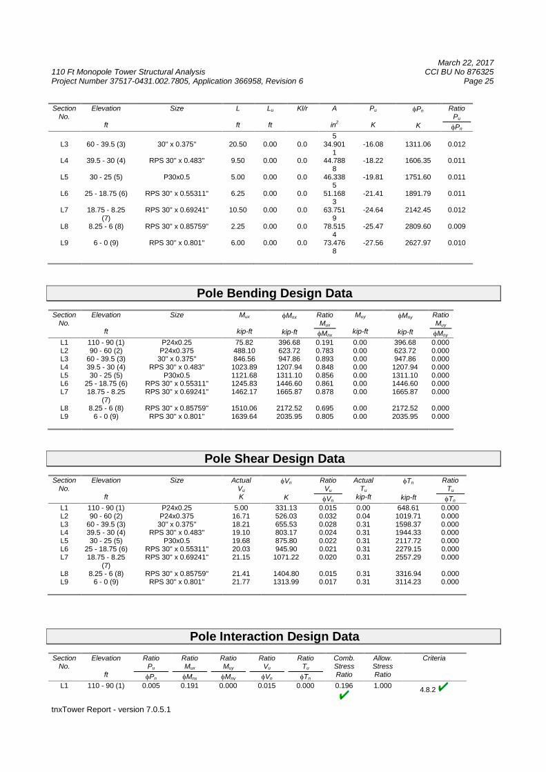
5L3 60 - 39.5 (3) 30'' x 0.375'' 20.50 0.00 0.0 34.901
1-16.08 1311.06 0.012
L4 39.5 - 30 (4) RPS 30'' x 0.483'' 9.50 0.00 0.0 44.7888
-18.22 1606.35 0.011
L5 30 - 25 (5) P30x0.5 5.00 0.00 0.0 46.3385
-19.81 1751.60 0.011
L6 25 - 18.75 (6) RPS 30'' x 0.55311'' 6.25 0.00 0.0 51.1683
-21.41 1891.79 0.011
L7 18.75 - 8.25(7)
RPS 30'' x 0.69241'' 10.50 0.00 0.0 63.7519
-24.64 2142.45 0.012
L8 8.25 - 6 (8) RPS 30'' x 0.85759'' 2.25 0.00 0.0 78.5154
-25.47 2809.60 0.009
L9 6 - 0 (9) RPS 30'' x 0.801'' 6.00 0.00 0.0 73.4768
-27.56 2627.97 0.010
Pole Bending Design Data
SectionNo.
Elevation
ft
Size Mux
kip-ft
Mnx
kip-ft
RatioMux
Mnx
Muy
kip-ft
Mny
kip-ft
RatioMuy
Mny
L1 110 - 90 (1) P24x0.25 75.82 396.68 0.191 0.00 396.68 0.000L2 90 - 60 (2) P24x0.375 488.10 623.72 0.783 0.00 623.72 0.000L3 60 - 39.5 (3) 30'' x 0.375'' 846.56 947.86 0.893 0.00 947.86 0.000L4 39.5 - 30 (4) RPS 30'' x 0.483'' 1023.89 1207.94 0.848 0.00 1207.94 0.000L5 30 - 25 (5) P30x0.5 1121.68 1311.10 0.856 0.00 1311.10 0.000L6 25 - 18.75 (6) RPS 30'' x 0.55311'' 1245.83 1446.60 0.861 0.00 1446.60 0.000L7 18.75 - 8.25
(7)RPS 30'' x 0.69241'' 1462.17 1665.87 0.878 0.00 1665.87 0.000
L8 8.25 - 6 (8) RPS 30'' x 0.85759'' 1510.06 2172.52 0.695 0.00 2172.52 0.000L9 6 - 0 (9) RPS 30'' x 0.801'' 1639.64 2035.95 0.805 0.00 2035.95 0.000
Pole Shear Design Data
SectionNo.
Elevation
ft
Size ActualVu
K
Vn
K
RatioVu
Vn
ActualTu
kip-ft
Tn
kip-ft
RatioTu
Tn
L1 110 - 90 (1) P24x0.25 5.00 331.13 0.015 0.00 648.61 0.000L2 90 - 60 (2) P24x0.375 16.71 526.03 0.032 0.04 1019.71 0.000L3 60 - 39.5 (3) 30'' x 0.375'' 18.21 655.53 0.028 0.31 1598.37 0.000L4 39.5 - 30 (4) RPS 30'' x 0.483'' 19.10 803.17 0.024 0.31 1944.33 0.000L5 30 - 25 (5) P30x0.5 19.68 875.80 0.022 0.31 2117.72 0.000L6 25 - 18.75 (6) RPS 30'' x 0.55311'' 20.03 945.90 0.021 0.31 2279.15 0.000L7 18.75 - 8.25
(7)RPS 30'' x 0.69241'' 21.15 1071.22 0.020 0.31 2557.29 0.000
L8 8.25 - 6 (8) RPS 30'' x 0.85759'' 21.41 1404.80 0.015 0.31 3316.94 0.000L9 6 - 0 (9) RPS 30'' x 0.801'' 21.77 1313.99 0.017 0.31 3114.23 0.000
Pole Interaction Design Data
SectionNo.
Elevation
ft
RatioPu
Pn
RatioMux
Mnx
RatioMuy
Mny
RatioVu
Vn
RatioTu
Tn
Comb.StressRatio
Allow.StressRatio
Criteria
L1 110 - 90 (1) 0.005 0.191 0.000 0.015 0.000 0.196 1.0004.8.2
March 22, 2017110 Ft Monopole Tower Structural Analysis CCI BU No 876325Project Number 37517-0431.002.7805, Application 366958, Revision 6 Page 26
tnxTower Report - version 7.0.5.1
SectionNo.
Elevation
ft
RatioPu
Pn
RatioMux
Mnx
RatioMuy
Mny
RatioVu
Vn
RatioTu
Tn
Comb.StressRatio
Allow.StressRatio
Criteria
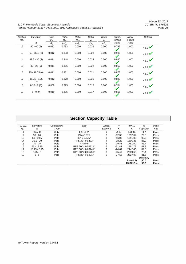
L2 90 - 60 (2) 0.012 0.783 0.000 0.032 0.000 0.795 1.0004.8.2
L3 60 - 39.5 (3) 0.012 0.893 0.000 0.028 0.000 0.906 1.0004.8.2
L4 39.5 - 30 (4) 0.011 0.848 0.000 0.024 0.000 0.860 1.0004.8.2
L5 30 - 25 (5) 0.011 0.856 0.000 0.022 0.000 0.867 1.0004.8.2
L6 25 - 18.75 (6) 0.011 0.861 0.000 0.021 0.000 0.873 1.0004.8.2
L7 18.75 - 8.25(7)
0.012 0.878 0.000 0.020 0.000 0.890 1.0004.8.2
L8 8.25 - 6 (8) 0.009 0.695 0.000 0.015 0.000 0.704 1.0004.8.2
L9 6 - 0 (9) 0.010 0.805 0.000 0.017 0.000 0.816 1.0004.8.2
Section Capacity Table
SectionNo.
Elevationft
ComponentType
Size CriticalElement
PK
øPallow
K%
CapacityPassFail
L1 110 - 90 Pole P24x0.25 1 -3.14 662.26 19.6 PassL2 90 - 60 Pole P24x0.375 2 -12.35 1052.07 79.5 PassL3 60 - 39.5 Pole 30'' x 0.375'' 3 -16.08 1311.06 90.6 PassL4 39.5 - 30 Pole RPS 30'' x 0.483'' 4 -18.22 1606.35 86.0 PassL5 30 - 25 Pole P30x0.5 5 -19.81 1751.60 86.7 PassL6 25 - 18.75 Pole RPS 30'' x 0.55311'' 6 -21.41 1891.79 87.3 PassL7 18.75 - 8.25 Pole RPS 30'' x 0.69241'' 7 -24.64 2142.45 89.0 PassL8 8.25 - 6 Pole RPS 30'' x 0.85759'' 8 -25.47 2809.60 70.4 PassL9 6 - 0 Pole RPS 30'' x 0.801'' 9 -27.56 2627.97 81.6 Pass
SummaryPole (L3) 90.6 Pass
RATING = 90.6 Pass
March 22, 2017110 Ft Monopole Tower Structural Analysis CCI BU No 876325Project Number 37517-0431.002.7805, Application 366958, Revision 6 Page 27
tnxTower Report - version 7.0.5.1
APPENDIX B
BASE LEVEL DRAWING
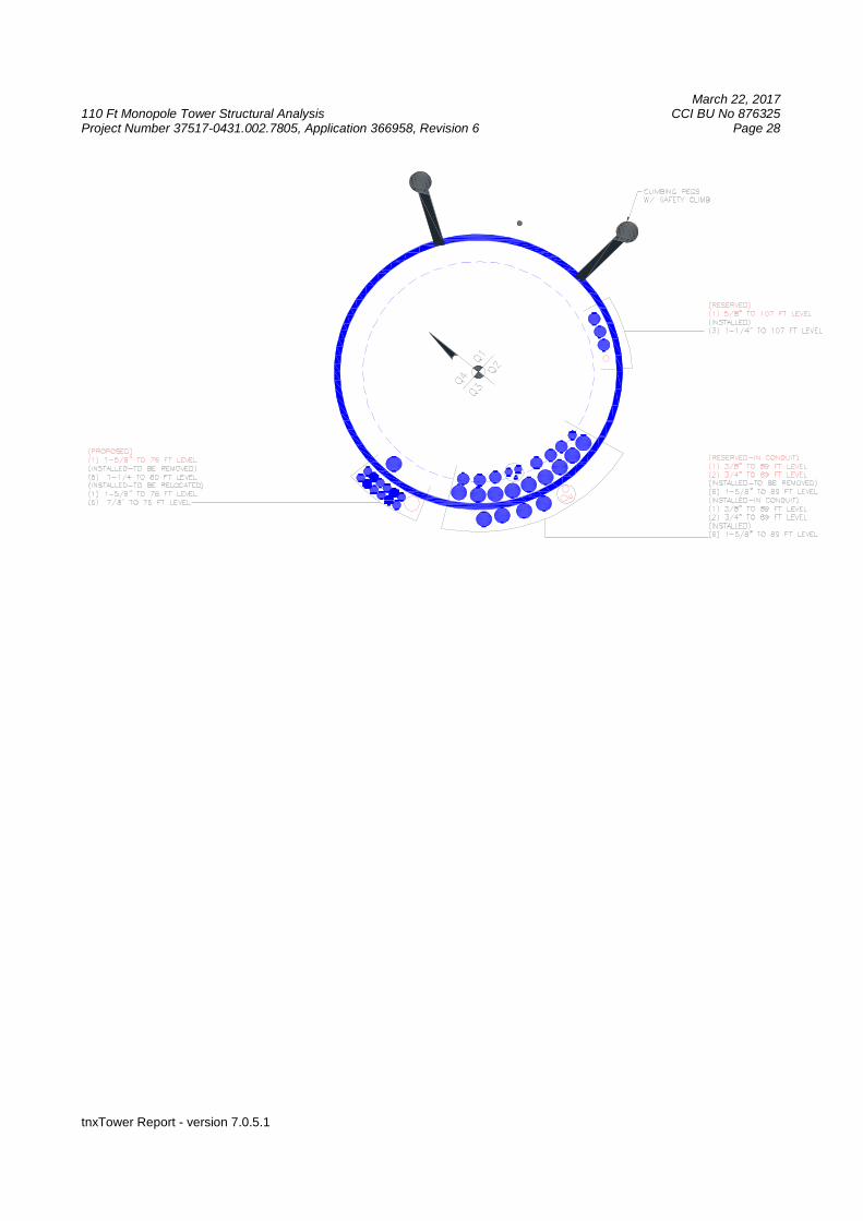
March 22, 2017110 Ft Monopole Tower Structural Analysis CCI BU No 876325Project Number 37517-0431.002.7805, Application 366958, Revision 6 Page 28
tnxTower Report - version 7.0.5.1
March 22, 2017110 Ft Monopole Tower Structural Analysis CCI BU No 876325Project Number 37517-0431.002.7805, Application 366958, Revision 6 Page 29
tnxTower Report - version 7.0.5.1
APPENDIX C
ADDITIONAL CALCULATIONS
Paul J. Ford and Company250 E Broad St, Suite 600
Columbus, OH 43215Phone: (614) 221-6679FAX: (555) 555-1235
Job:110-Ft. Monopole / Weston Square
Project: 37517-0431.002 / BU 876325Client: Crown Castle Drawn by: mherbert App'd:
Code: TIA-222-G Date: 03/22/17 Scale: NTSPath:
G:\TOWER\375_Crown_Castle\2017\37517-0431_876325_WESTON SQUARE\37517-0431.002.7805_SA_1378377\37517-0431.002.7805_Reinforced.eri
Dwg No. E-1
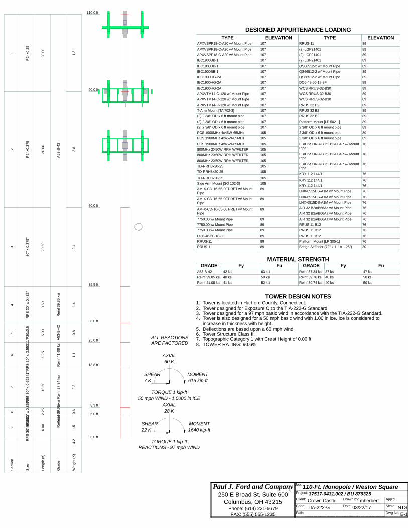
110.0 ft
90.0 ft
60.0 ft
39.5 ft
30.0 ft
25.0 ft
18.8 ft
8.3 ft
6.0 ft
0.0 ft
REACTIONS - 97 mph WINDTORQUE 1 kip-ft
22 K
SHEAR
1640 kip-ft
MOMENT
28 K
AXIAL
50 mph WIND - 1.0000 in ICE
TORQUE 1 kip-ft
7 K
SHEAR
615 kip-ft
MOMENT
60 K
AXIAL
ARE FACTOREDALL REACTIONS
Se
ctio
n1
23
45
67
89
Siz
eP
24
x0.2
5P
24
x0.3
75
30
"x
0.3
75
"R
PS
30
"x
0.4
83
"P
30
x0.5
RP
S3
0"
x0
.55
31
1"
RP
S3
0"
x0
.69
24
1"
RP
S3
0"
x0
.85
75
9"
RP
S3
0"
x0
.80
1"
Le
ng
th(f
t)2
0.0
03
0.0
02
0.5
09
.50
5.0
06
.25
10
.50
2.2
56
.00
Gra
de
A5
3-B
-42
Re
inf3
9.8
5ks
iA
53
-B-4
2R
ein
f4
1.0
8ks
iR
ein
f3
7.3
4ks
iR
ein
f3
9.7
6ks
iR
ein
f3
9.7
4ks
i
We
igh
t(K
)1
.32
.82
.41
.40
.81
.12
.30
.61
.51
4.2
APXVSPP18-C-A20 w/ Mount Pipe 107APXVSPP18-C-A20 w/ Mount Pipe 107APXVSPP18-C-A20 w/ Mount Pipe 107IBC1900BB-1 107IBC1900BB-1 107IBC1900BB-1 107IBC1900HG-2A 107IBC1900HG-2A 107IBC1900HG-2A 107APXVTM14-C-120 w/ Mount Pipe 107APXVTM14-C-120 w/ Mount Pipe 107APXVTM14-C-120 w/ Mount Pipe 107T-Arm Mount [TA 702-3] 107(2) 2 3/8" OD x 6 ft mount pipe 107(2) 2 3/8" OD x 6 ft mount pipe 107(2) 2 3/8" OD x 6 ft mount pipe 107PCS 1900MHz 4x45W-65MHz 105PCS 1900MHz 4x45W-65MHz 105PCS 1900MHz 4x45W-65MHz 105800MHz 2X50W RRH W/FILTER 105800MHz 2X50W RRH W/FILTER 105800MHz 2X50W RRH W/FILTER 105TD-RRH8x20-25 105TD-RRH8x20-25 105TD-RRH8x20-25 105Side Arm Mount [SO 102-3] 105AM-X-CD-16-65-00T-RET w/ MountPipe
89AM-X-CD-16-65-00T-RET w/ MountPipe
89AM-X-CD-16-65-00T-RET w/ MountPipe
897750.00 w/ Mount Pipe 897750.00 w/ Mount Pipe 897750.00 w/ Mount Pipe 89DC6-48-60-18-8F 89RRUS-11 89RRUS-11 89RRUS-11 89(2) LGP21401 89(2) LGP21401 89(2) LGP21401 89QS66512-2 w/ Mount Pipe 89QS66512-2 w/ Mount Pipe 89QS66512-2 w/ Mount Pipe 89DC6-48-60-18-8F 89WCS RRUS-32-B30 89WCS RRUS-32-B30 89WCS RRUS-32-B30 89RRUS 32 B2 89RRUS 32 B2 89RRUS 32 B2 89Platform Mount [LP 502-1] 892 3/8" OD x 6 ft mount pipe 892 3/8" OD x 6 ft mount pipe 892 3/8" OD x 6 ft mount pipe 89ERICSSON AIR 21 B2A B4P w/ MountPipe
76ERICSSON AIR 21 B2A B4P w/ MountPipe
76ERICSSON AIR 21 B2A B4P w/ MountPipe
76KRY 112 144/1 76KRY 112 144/1 76KRY 112 144/1 76LNX-6515DS-A1M w/ Mount Pipe 76LNX-6515DS-A1M w/ Mount Pipe 76LNX-6515DS-A1M w/ Mount Pipe 76AIR 32 B2a/B66Aa w/ Mount Pipe 76AIR 32 B2a/B66Aa w/ Mount Pipe 76AIR 32 B2a/B66Aa w/ Mount Pipe 76RRUS 11 B12 76RRUS 11 B12 76RRUS 11 B12 76Platform Mount [LP 305-1] 76Bridge Stiffener (72" x 11" x 1.25") 30DESIGNED APPURTENANCE LOADING
TYPE TYPEELEVATION ELEVATIONAPXVSPP18-C-A20 w/ Mount Pipe 107
APXVSPP18-C-A20 w/ Mount Pipe 107
APXVSPP18-C-A20 w/ Mount Pipe 107
IBC1900BB-1 107
IBC1900BB-1 107
IBC1900BB-1 107
IBC1900HG-2A 107
IBC1900HG-2A 107
IBC1900HG-2A 107
APXVTM14-C-120 w/ Mount Pipe 107
APXVTM14-C-120 w/ Mount Pipe 107
APXVTM14-C-120 w/ Mount Pipe 107
T-Arm Mount [TA 702-3] 107
(2) 2 3/8" OD x 6 ft mount pipe 107
(2) 2 3/8" OD x 6 ft mount pipe 107
(2) 2 3/8" OD x 6 ft mount pipe 107
PCS 1900MHz 4x45W-65MHz 105
PCS 1900MHz 4x45W-65MHz 105
PCS 1900MHz 4x45W-65MHz 105
800MHz 2X50W RRH W/FILTER 105
800MHz 2X50W RRH W/FILTER 105
800MHz 2X50W RRH W/FILTER 105
TD-RRH8x20-25 105
TD-RRH8x20-25 105
TD-RRH8x20-25 105
Side Arm Mount [SO 102-3] 105
AM-X-CD-16-65-00T-RET w/ MountPipe
89
AM-X-CD-16-65-00T-RET w/ MountPipe
89
AM-X-CD-16-65-00T-RET w/ MountPipe
89
7750.00 w/ Mount Pipe 89
7750.00 w/ Mount Pipe 89
7750.00 w/ Mount Pipe 89
DC6-48-60-18-8F 89
RRUS-11 89
RRUS-11 89
RRUS-11 89
(2) LGP21401 89
(2) LGP21401 89
(2) LGP21401 89
QS66512-2 w/ Mount Pipe 89
QS66512-2 w/ Mount Pipe 89
QS66512-2 w/ Mount Pipe 89
DC6-48-60-18-8F 89
WCS RRUS-32-B30 89
WCS RRUS-32-B30 89
WCS RRUS-32-B30 89
RRUS 32 B2 89
RRUS 32 B2 89
RRUS 32 B2 89
Platform Mount [LP 502-1] 89
2 3/8" OD x 6 ft mount pipe 89
2 3/8" OD x 6 ft mount pipe 89
2 3/8" OD x 6 ft mount pipe 89
ERICSSON AIR 21 B2A B4P w/ MountPipe
76
ERICSSON AIR 21 B2A B4P w/ MountPipe
76
ERICSSON AIR 21 B2A B4P w/ MountPipe
76
KRY 112 144/1 76
KRY 112 144/1 76
KRY 112 144/1 76
LNX-6515DS-A1M w/ Mount Pipe 76
LNX-6515DS-A1M w/ Mount Pipe 76
LNX-6515DS-A1M w/ Mount Pipe 76
AIR 32 B2a/B66Aa w/ Mount Pipe 76
AIR 32 B2a/B66Aa w/ Mount Pipe 76
AIR 32 B2a/B66Aa w/ Mount Pipe 76
RRUS 11 B12 76
RRUS 11 B12 76
RRUS 11 B12 76
Platform Mount [LP 305-1] 76
Bridge Stiffener (72" x 11" x 1.25") 30
MATERIAL STRENGTHGRADE GRADEFy FyFu Fu
A53-B-42 42 ksi 63 ksi
Reinf 39.85 ksi 40 ksi 50 ksi
Reinf 41.08 ksi 41 ksi 52 ksi
Reinf 37.34 ksi 37 ksi 47 ksi
Reinf 39.76 ksi 40 ksi 50 ksi
Reinf 39.74 ksi 40 ksi 50 ksi
TOWER DESIGN NOTES1. Tower is located in Hartford County, Connecticut.2. Tower designed for Exposure C to the TIA-222-G Standard.3. Tower designed for a 97 mph basic wind in accordance with the TIA-222-G Standard.4. Tower is also designed for a 50 mph basic wind with 1.00 in ice. Ice is considered to
increase in thickness with height.5. Deflections are based upon a 60 mph wind.6. Tower Structure Class II.7. Topographic Category 1 with Crest Height of 0.00 ft8. TOWER RATING: 90.6%
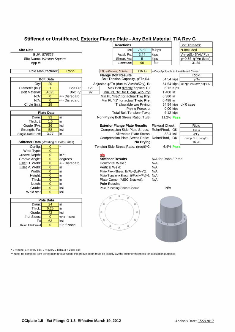
Reactions Bolt Threads:
Site Data Mu 75.82 ft-kips N-Included
BU#: Axial, Pu: 3.14 kips Vn=φ(0.45*Ab*Fu)Site Name: Shear, Vu: 5 kips φ=0.75, φ*Vn (kips):
App #: Elevation: 90 feet 31.81
Pole Manufacturer: Rohn If No stiffeners, Criteria: TIA G <-Only Applcable to Unstiffened Cases
Flange Bolt Results RigidBolt Tension Capacity, φ*Tn,B1: 54.54 kips φ*Tn
Qty: 20 Adjusted φ*Tn (due to Vu=Vu/Qty), B: 54.54 kips φTn[(1-(Vu/φVn)^2]^0.5
Diameter (in.): 1 Bolt Fu: 120 Max Bolt directly applied Tu: 6.12 KipsBolt Material: A325 Bolt Fy: 92 Min. PL "tc" for B cap. w/o Pry: 1.488 in
N/A: 0 <-- Disregard Min PL "treq" for actual T w/ Pry: 0.380 inN/A: 0 <-- Disregard Min PL "t1" for actual T w/o Pry: 0.498 in
Circle (in.): 29 T allowable w/o Prying: 54.54 kips α'<0 casePrying Force, q: 0.00 kips
Total Bolt Tension=Tu+q: 6.12 kips
Diam: 32 in Non-Prying Bolt Stress Ratio, Tu/B: 11.2% PassThick, t: 1.5 in
Grade (Fy): 36 ksi Exterior Flange Plate Results Flexural Check RigidStrength, Fu: 58 ksi Compression Side Plate Stress: Rohn/Pirod, OK TIA G
Single-Rod B-eff: 3.77 in Allowable Plate Stress: 32.4 ksi φ*Fy
Compression Plate Stress Ratio: Rohn/Pirod, OK Comp. Y.L. Length:
No Prying 16.28
Config: 0 * Tension Side Stress Ratio, (treq/t)^2: 6.4% PassWeld Type: 0
Groove Depth: 0 in ** n/aGroove Angle: 0 degrees Stiffener Results N/A for Rohn / PirodFillet H. Weld: 0 <-- Disregard Horizontal Weld : N/AFillet V. Weld: 0 in Vertical Weld: N/A
Width: 0 in Plate Flex+Shear, fb/Fb+(fv/Fv)^2: N/AHeight: 0 in Plate Tension+Shear, ft/Ft+(fv/Fv)^2: N/AThick: 0 in Plate Comp. (AISC Bracket): N/ANotch: 0 in Pole ResultsGrade: 0 ksi Pole Punching Shear Check: N/A
Weld str.: 0 ksi
Diam: 24 inThick: 0.25 in
Grade: 42 ksi# of Sides: 0 "0" IF Round
Fu 63 ksiReinf. Fillet Weld 0 "0" if None
* 0 = none, 1 = every bolt, 2 = every 2 bolts, 3 = 2 per bolt
** Note: for complete joint penetration groove welds the groove depth must be exactly 1/2 the stiffener thickness for calculation purposes
Plate Data
Stiffener Data (Welding at Both Sides)
Pole Data
Stiffened or Unstiffened, Exterior Flange Plate - Any Bolt Material TIA Rev G
876325
Weston Square
Bolt Data
CCIplate 1.5 - Ext Flange G 1.3, Effective March 19, 2012 Analysis Date: 3/22/2017

Reactions Bolt Threads:
Site Data Mu 75.82 ft-kips N-Included
BU#: Axial, Pu: 3.14 kips Vn=φ(0.45*Ab*Fu)Site Name: Shear, Vu: 5 kips φ=0.75, φ*Vn (kips):
App #: Elevation: 90 feet 31.81
Pole Manufacturer: Rohn If No stiffeners, Criteria: TIA G <-Only Applcable to Unstiffened Cases
Flange Bolt Results RigidBolt Tension Capacity, φ*Tn,B1: 54.54 kips φ*Tn
Qty: 20 Adjusted φ*Tn (due to Vu=Vu/Qty), B: 54.54 kips φTn[(1-(Vu/φVn)^2]^0.5
Diameter (in.): 1 Bolt Fu: 120 Max Bolt directly applied Tu: 6.12 KipsBolt Material: A325 Bolt Fy: 92 Min. PL "tc" for B cap. w/o Pry: 1.488 in
N/A: 0 <-- Disregard Min PL "treq" for actual T w/ Pry: 0.380 inN/A: 0 <-- Disregard Min PL "t1" for actual T w/o Pry: 0.498 in
Circle (in.): 29 T allowable w/o Prying: 54.54 kips α'<0 casePrying Force, q: 0.00 kips
Total Bolt Tension=Tu+q: 6.12 kips
Diam: 32 in Non-Prying Bolt Stress Ratio, Tu/B: 11.2% PassThick, t: 1.5 in
Grade (Fy): 36 ksi Exterior Flange Plate Results Flexural Check RigidStrength, Fu: 58 ksi Compression Side Plate Stress: Rohn/Pirod, OK TIA G
Single-Rod B-eff: 3.77 in Allowable Plate Stress: 32.4 ksi φ*Fy
Compression Plate Stress Ratio: Rohn/Pirod, OK Comp. Y.L. Length:
No Prying 16.28
Config: 0 * Tension Side Stress Ratio, (treq/t)^2: 6.4% PassWeld Type: 0
Groove Depth: 0 in ** n/aGroove Angle: 0 degrees Stiffener Results N/A for Rohn / PirodFillet H. Weld: 0 <-- Disregard Horizontal Weld : N/AFillet V. Weld: 0 in Vertical Weld: N/A
Width: 0 in Plate Flex+Shear, fb/Fb+(fv/Fv)^2: N/AHeight: 0 in Plate Tension+Shear, ft/Ft+(fv/Fv)^2: N/AThick: 0 in Plate Comp. (AISC Bracket): N/ANotch: 0 in Pole ResultsGrade: 0 ksi Pole Punching Shear Check: N/A
Weld str.: 0 ksi
Diam: 24 inThick: 0.375 in
Grade: 42 ksi# of Sides: 0 "0" IF Round
Fu 63 ksiReinf. Fillet Weld 0 "0" if None
* 0 = none, 1 = every bolt, 2 = every 2 bolts, 3 = 2 per bolt
** Note: for complete joint penetration groove welds the groove depth must be exactly 1/2 the stiffener thickness for calculation purposes
Plate Data
Stiffener Data (Welding at Both Sides)
Pole Data
Stiffened or Unstiffened, Exterior Flange Plate - Any Bolt Material TIA Rev G
876325
Weston Square
Bolt Data
CCIplate 1.5 - Ext Flange G 1.3, Effective March 19, 2012 Analysis Date: 3/22/2017
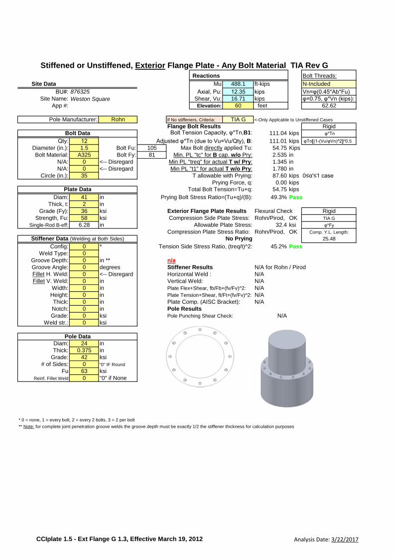
Reactions Bolt Threads:
Site Data Mu 488.1 ft-kips N-Included
BU#: Axial, Pu: 12.35 kips Vn=φ(0.45*Ab*Fu)Site Name: Shear, Vu: 16.71 kips φ=0.75, φ*Vn (kips):
App #: Elevation: 60 feet 62.62
Pole Manufacturer: Rohn If No stiffeners, Criteria: TIA G <-Only Applcable to Unstiffened Cases
Flange Bolt Results RigidBolt Tension Capacity, φ*Tn,B1: 111.04 kips φ*Tn
Qty: 12 Adjusted φ*Tn (due to Vu=Vu/Qty), B: 111.01 kips φTn[(1-(Vu/φVn)^2]^0.5
Diameter (in.): 1.5 Bolt Fu: 105 Max Bolt directly applied Tu: 54.75 KipsBolt Material: A325 Bolt Fy: 81 Min. PL "tc" for B cap. w/o Pry: 2.535 in
N/A: 0 <-- Disregard Min PL "treq" for actual T w/ Pry: 1.345 inN/A: 0 <-- Disregard Min PL "t1" for actual T w/o Pry: 1.780 in
Circle (in.): 35 T allowable with Prying: 87.60 kips 0≤α'≤1 casePrying Force, q: 0.00 kips
Total Bolt Tension=Tu+q: 54.75 kips
Diam: 41 in Prying Bolt Stress Ratio=(Tu+q)/(B): 49.3% PassThick, t: 2 in
Grade (Fy): 36 ksi Exterior Flange Plate Results Flexural Check RigidStrength, Fu: 58 ksi Compression Side Plate Stress: Rohn/Pirod, OK TIA G
Single-Rod B-eff: 6.28 in Allowable Plate Stress: 32.4 ksi φ*Fy
Compression Plate Stress Ratio: Rohn/Pirod, OK Comp. Y.L. Length:
No Prying 25.48
Config: 0 * Tension Side Stress Ratio, (treq/t)^2: 45.2% PassWeld Type: 0
Groove Depth: 0 in ** n/aGroove Angle: 0 degrees Stiffener Results N/A for Rohn / PirodFillet H. Weld: 0 <-- Disregard Horizontal Weld : N/AFillet V. Weld: 0 in Vertical Weld: N/A
Width: 0 in Plate Flex+Shear, fb/Fb+(fv/Fv)^2: N/AHeight: 0 in Plate Tension+Shear, ft/Ft+(fv/Fv)^2: N/AThick: 0 in Plate Comp. (AISC Bracket): N/ANotch: 0 in Pole ResultsGrade: 0 ksi Pole Punching Shear Check: N/A
Weld str.: 0 ksi
Diam: 24 inThick: 0.375 in
Grade: 42 ksi# of Sides: 0 "0" IF Round
Fu 63 ksiReinf. Fillet Weld 0 "0" if None
* 0 = none, 1 = every bolt, 2 = every 2 bolts, 3 = 2 per bolt
** Note: for complete joint penetration groove welds the groove depth must be exactly 1/2 the stiffener thickness for calculation purposes
Plate Data
Stiffener Data (Welding at Both Sides)
Pole Data
Stiffened or Unstiffened, Exterior Flange Plate - Any Bolt Material TIA Rev G
876325
Weston Square
Bolt Data
CCIplate 1.5 - Ext Flange G 1.3, Effective March 19, 2012 Analysis Date: 3/22/2017

Reactions Bolt Threads:
Site Data Mu 488.1 ft-kips N-Included
BU#: Axial, Pu: 12.35 kips Vn=φ(0.45*Ab*Fu)Site Name: Shear, Vu: 16.71 kips φ=0.75, φ*Vn (kips):
App #: Elevation: 60 feet 62.62
Pole Manufacturer: Rohn If No stiffeners, Criteria: TIA G <-Only Applcable to Unstiffened Cases
Flange Bolt Results RigidBolt Tension Capacity, φ*Tn,B1: 111.04 kips φ*Tn
Qty: 12 Adjusted φ*Tn (due to Vu=Vu/Qty), B: 111.01 kips φTn[(1-(Vu/φVn)^2]^0.5
Diameter (in.): 1.5 Bolt Fu: 105 Max Bolt directly applied Tu: 54.75 KipsBolt Material: A325 Bolt Fy: 81 Min. PL "tc" for B cap. w/o Pry: 1.376 in
N/A: 0 <-- Disregard Min PL "treq" for actual T w/ Pry: 0.720 inN/A: 0 <-- Disregard Min PL "t1" for actual T w/o Pry: 0.966 in
Circle (in.): 35 T allowable w/o Prying: 111.04 kips α'<0 casePrying Force, q: 0.00 kips
Total Bolt Tension=Tu+q: 54.75 kips
Diam: 41 in Non-Prying Bolt Stress Ratio, Tu/B: 49.3% PassThick, t: 2 in
Grade (Fy): 36 ksi Exterior Flange Plate Results Flexural Check RigidStrength, Fu: 58 ksi Compression Side Plate Stress: Rohn/Pirod, OK TIA G
Single-Rod B-eff: 7.85 in Allowable Plate Stress: 32.4 ksi φ*Fy
Compression Plate Stress Ratio: Rohn/Pirod, OK Comp. Y.L. Length:
No Prying 18.03
Config: 0 * Tension Side Stress Ratio, (treq/t)^2: 13.0% PassWeld Type: 0
Groove Depth: 0 in ** n/aGroove Angle: 0 degrees Stiffener Results N/A for Rohn / PirodFillet H. Weld: 0 <-- Disregard Horizontal Weld : N/AFillet V. Weld: 0 in Vertical Weld: N/A
Width: 0 in Plate Flex+Shear, fb/Fb+(fv/Fv)^2: N/AHeight: 0 in Plate Tension+Shear, ft/Ft+(fv/Fv)^2: N/AThick: 0 in Plate Comp. (AISC Bracket): N/ANotch: 0 in Pole ResultsGrade: 0 ksi Pole Punching Shear Check: N/A
Weld str.: 0 ksi
Diam: 30 inThick: 0.375 in
Grade: 42 ksi# of Sides: 0 "0" IF Round
Fu 63 ksiReinf. Fillet Weld 0 "0" if None
* 0 = none, 1 = every bolt, 2 = every 2 bolts, 3 = 2 per bolt
** Note: for complete joint penetration groove welds the groove depth must be exactly 1/2 the stiffener thickness for calculation purposes
Plate Data
Stiffener Data (Welding at Both Sides)
Pole Data
Stiffened or Unstiffened, Exterior Flange Plate - Any Bolt Material TIA Rev G
876325
Weston Square
Bolt Data
CCIplate 1.5 - Ext Flange G 1.3, Effective March 19, 2012 Analysis Date: 3/22/2017

Reactions Bolt Threads:
Site Data Mu 448.84 ft-kips N-Included
BU#: Axial, Pu: 9.85 kips Vn=φ(0.45*Ab*Fu)Site Name: Shear, Vu: 19.1 kips φ=0.75, φ*Vn (kips):
App #: Elevation: 30 feet 62.62
Pole Manufacturer: Other If No stiffeners, Criteria: TIA G <-Only Applcable to Unstiffened Cases
Flange Bolt Results RigidBolt Tension Capacity, φ*Tn,B1: 111.04 kips φ*Tn
Qty: 12 Adjusted φ*Tn (due to Vu=Vu/Qty), B: 111.00 kips φTn[(1-(Vu/φVn)^2]^0.5
Diameter (in.): 1.5 Bolt Fu: 105 Max Bolt directly applied Tu: 50.48 KipsBolt Material: A325 Bolt Fy: 81 Min. PL "tc" for B cap. w/o Pry: 1.376 in
N/A: 0 <-- Disregard Min PL "treq" for actual T w/ Pry: 0.691 inN/A: 0 <-- Disregard Min PL "t1" for actual T w/o Pry: 0.928 in
Circle (in.): 35 T allowable w/o Prying: 111.04 kips α'<0 casePrying Force, q: 0.00 kips
Total Bolt Tension=Tu+q: 50.48 kips
Diam: 41 in Non-Prying Bolt Stress Ratio, Tu/B: 45.5% PassThick, t: 2 in
Grade (Fy): 36 ksi Exterior Flange Plate Results Flexural Check RigidStrength, Fu: 58 ksi Compression Side Plate Stress: 10.6 ksi TIA G
Single-Rod B-eff: 7.85 in Allowable Plate Stress: 32.4 ksi φ*Fy
Compression Plate Stress Ratio: 32.8% Pass Comp. Y.L. Length:
No Prying 18.03
Config: 0 * Tension Side Stress Ratio, (treq/t)^2: 12.0% PassWeld Type: 0
Groove Depth: 0 in ** n/aGroove Angle: 0 degrees Stiffener ResultsFillet H. Weld: 0 <-- Disregard Horizontal Weld : n/aFillet V. Weld: 0 in Vertical Weld: n/a
Width: 0 in Plate Flex+Shear, fb/Fb+(fv/Fv)^2: n/aHeight: 0 in Plate Tension+Shear, ft/Ft+(fv/Fv)^2: n/aThick: 0 in Plate Comp. (AISC Bracket): n/aNotch: 0 in Pole ResultsGrade: 0 ksi Pole Punching Shear Check: n/a
Weld str.: 0 ksi
Diam: 30 inThick: 0.375 in
Grade: 42 ksi# of Sides: 0 "0" IF Round
Fu 63 ksiReinf. Fillet Weld 0 "0" if None
* 0 = none, 1 = every bolt, 2 = every 2 bolts, 3 = 2 per bolt
** Note: for complete joint penetration groove welds the groove depth must be exactly 1/2 the stiffener thickness for calculation purposes
Plate Data
Stiffener Data (Welding at Both Sides)
Pole Data
Stiffened or Unstiffened, Exterior Flange Plate - Any Bolt Material TIA Rev G
876325
Weston Square
Bolt Data
CCIplate 1.5 - Ext Flange G 1.3, Effective March 19, 2012 Analysis Date: 3/22/2017
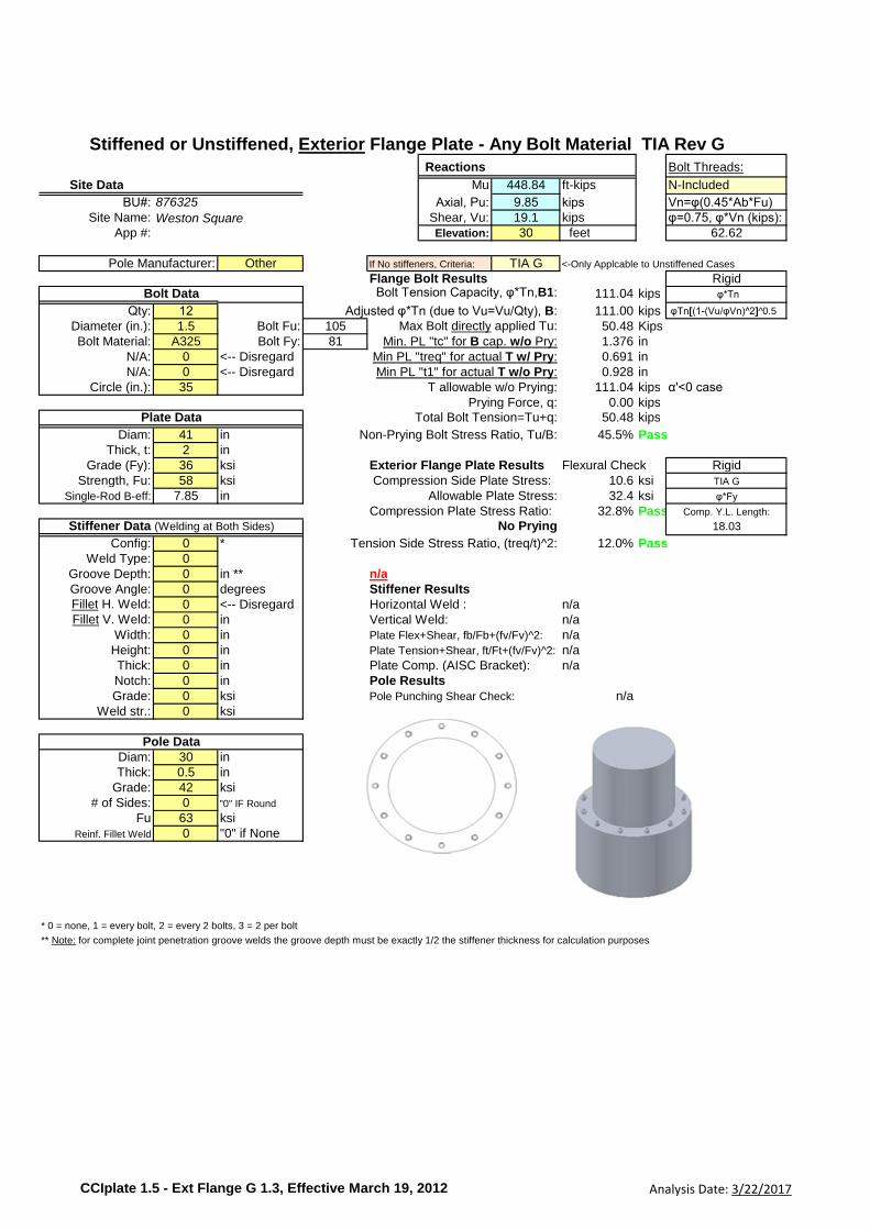
Reactions Bolt Threads:
Site Data Mu 448.84 ft-kips N-Included
BU#: Axial, Pu: 9.85 kips Vn=φ(0.45*Ab*Fu)Site Name: Shear, Vu: 19.1 kips φ=0.75, φ*Vn (kips):
App #: Elevation: 30 feet 62.62
Pole Manufacturer: Other If No stiffeners, Criteria: TIA G <-Only Applcable to Unstiffened Cases
Flange Bolt Results RigidBolt Tension Capacity, φ*Tn,B1: 111.04 kips φ*Tn
Qty: 12 Adjusted φ*Tn (due to Vu=Vu/Qty), B: 111.00 kips φTn[(1-(Vu/φVn)^2]^0.5
Diameter (in.): 1.5 Bolt Fu: 105 Max Bolt directly applied Tu: 50.48 KipsBolt Material: A325 Bolt Fy: 81 Min. PL "tc" for B cap. w/o Pry: 1.376 in
N/A: 0 <-- Disregard Min PL "treq" for actual T w/ Pry: 0.691 inN/A: 0 <-- Disregard Min PL "t1" for actual T w/o Pry: 0.928 in
Circle (in.): 35 T allowable w/o Prying: 111.04 kips α'<0 casePrying Force, q: 0.00 kips
Total Bolt Tension=Tu+q: 50.48 kips
Diam: 41 in Non-Prying Bolt Stress Ratio, Tu/B: 45.5% PassThick, t: 2 in
Grade (Fy): 36 ksi Exterior Flange Plate Results Flexural Check RigidStrength, Fu: 58 ksi Compression Side Plate Stress: 10.6 ksi TIA G
Single-Rod B-eff: 7.85 in Allowable Plate Stress: 32.4 ksi φ*Fy
Compression Plate Stress Ratio: 32.8% Pass Comp. Y.L. Length:
No Prying 18.03
Config: 0 * Tension Side Stress Ratio, (treq/t)^2: 12.0% PassWeld Type: 0
Groove Depth: 0 in ** n/aGroove Angle: 0 degrees Stiffener ResultsFillet H. Weld: 0 <-- Disregard Horizontal Weld : n/aFillet V. Weld: 0 in Vertical Weld: n/a
Width: 0 in Plate Flex+Shear, fb/Fb+(fv/Fv)^2: n/aHeight: 0 in Plate Tension+Shear, ft/Ft+(fv/Fv)^2: n/aThick: 0 in Plate Comp. (AISC Bracket): n/aNotch: 0 in Pole ResultsGrade: 0 ksi Pole Punching Shear Check: n/a
Weld str.: 0 ksi
Diam: 30 inThick: 0.5 in
Grade: 42 ksi# of Sides: 0 "0" IF Round
Fu 63 ksiReinf. Fillet Weld 0 "0" if None
* 0 = none, 1 = every bolt, 2 = every 2 bolts, 3 = 2 per bolt
** Note: for complete joint penetration groove welds the groove depth must be exactly 1/2 the stiffener thickness for calculation purposes
Plate Data
Stiffener Data (Welding at Both Sides)
Pole Data
Stiffened or Unstiffened, Exterior Flange Plate - Any Bolt Material TIA Rev G
876325
Weston Square
Bolt Data
CCIplate 1.5 - Ext Flange G 1.3, Effective March 19, 2012 Analysis Date: 3/22/2017
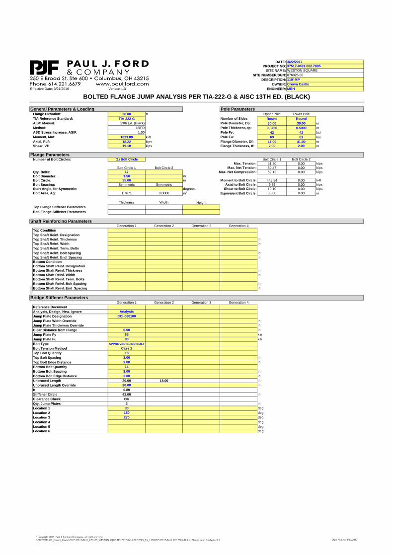
DATE:PROJECT NO:
SITE NAME:
SITE NUMBER/BUN:
DESCRIPTION:
OWNER:
Effective Date: 3/21/2016 Verison 1.3 ENGINEER:
Flange Elevation: 30.00 ft Upper Pole Lower Pole
TIA Reference Standard: TIA-222-G Number of Sides Round Round
AISC Manual: 13th Ed. (Black) Pole Diameter, Dp: 30.00 30.00 in
Method: LRFD Pole Thickness, tp: 0.3750 0.5000 in
ASD Stress Increase, ASIF: 1.00 Pole Fy: 42 42 ksi
Moment, Muf: 1023.89 k-ft Pole Fu: 63 63 ksi
Axial, Puf: 18.22 kips Flange Diameter, Df: 41.00 41.00 in
Shear, Vf: 19.10 kips Flange Thickness, tf: 2.00 2.00 in
Number of Bolt Circles: (1) Bolt Circle Bolt Circle 1 Bolt Circle 2Max. Tension: 51.30 0.00 kips
Bolt Circle 1 Bolt Circle 2 Max. Net Tension: 50.47 0.00 kips
Qty. Bolts: 12 Max. Net Compression: 52.12 0.00 kips
Bolt Diameter: 1.50 in
Bolt Circle: 35.00 in Moment to Bolt Circle: 448.84 0.00 k-ft
Bolt Spacing: Symmetric Symmetric Axial to Bolt Circle: 9.85 0.00 kips
Start Angle, for Symmetric: degrees Shear to Bolt Circle: 19.10 0.00 kips
Bolt Area, Ag: 1.7671 0.0000 in2Equivalent Bolt Circle: 35.00 0.00 in
Thickness Width Height
Top Flange Stiffener Parameters
Bot. Flange Stiffener Parameters
Generation 1 Generation 2 Generation 3 Generation 4
Top Condition
Top Shaft Reinf. Designation
Top Shaft Reinf. Thickness in
Top Shaft Reinf. Width in
Top Shaft Reinf. Term. Bolts
Top Shaft Reinf. Bolt Spacing in
Top Shaft Reinf. End Spacing in
Bottom Condition
Bottom Shaft Reinf. Designation
Bottom Shaft Reinf. Thickness in
Bottom Shaft Reinf. Width in
Bottom Shaft Reinf. Term. Bolts
Bottom Shaft Reinf. Bolt Spacing in
Bottom Shaft Reinf. End Spacing in
Generation 1 Generation 2 Generation 3 Generation 4
Reference Document
Analysis, Design, New, Ignore Analysis
Jump Plate Designation CCI-060100
Jump Plate Width Override in
Jump Plate Thickness Override in
Clear Distance from Flange 0.50 in
Jump Plate Fy 65 ksi
Jump Plate Fu 80 ksi
Bolt Type APPROVED BLIND BOLT
Bolt Tension Method Case 2
Top Bolt Quantity 18
Top Bolt Spacing 3.00 in
Top Bolt Edge Distance 3.00 in
Bottom Bolt Quantity 14
Bottom Bolt Spacing 3.00 in
Bottom Bolt Edge Distance 3.00 in
Unbraced Length 20.00 18.00 in
Unbraced Length Override 20.00 in
K 0.80
Stiffener Circle 43.00 in
Clearance Check OK
Qty. Jump Plates 3 in
Location 1 30 deg
Location 2 150 deg
Location 3 270 deg
Location 4 deg
Location 5 deg
Location 6 deg
Shaft Reinforcing Parameters
3/22/201737517-0431.002.7805
WESTON SQUARE
876325.00
110' MP
Crown Castle
MEH
General Parameters & Loading
BOLTED FLANGE JUMP ANALYSIS PER TIA-222-G & AISC 13TH ED. (BLACK)
Pole Parameters
Flange Parameters
Bridge Stiffener Parameters
© Copyright 2015 Paul J. Ford and Company, all right reserved.
G:\TOWER\375_Crown_Castle\2017\37517-0431_876325_WESTON SQUARE\37517-0431.002.7805_SA_1378377\37517-0431.002.7805- Bolted Flange Jump Analysis v1.3 Date Printed: 3/22/2017
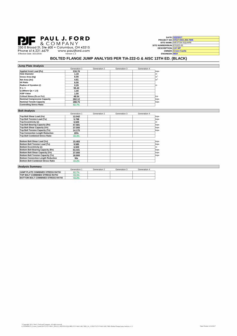
DATE:PROJECT NO:
SITE NAME:
SITE NUMBER/BUN:
DESCRIPTION:
OWNER:
Effective Date: 3/21/2016 Verison 1.3 ENGINEER:
3/22/201737517-0431.002.7805
WESTON SQUARE
876325.00
110' MP
Crown Castle
MEH
BOLTED FLANGE JUMP ANALYSIS PER TIA-222-G & AISC 13TH ED. (BLACK)
Generation 1 Generation 2 Generation 3 Generation 4
Applied Axial Load (Pu) 216.76 kips
Hole Diameter 1.19 in
Gross Area (Ag) 6.00 in2
Net Area (An) 4.81 in2
b/t Ratio 6.00Radius of Gyration (r) 0.29 in
K L / r 55.43Q (Where Qa = 1.0) 1.00ASIF Value 1.00Critical Stress (Fa or Fcr) 48.54 ksi
Nominal Compressive Capacity 262.12 kips
Nominal Tensile Capacity 288.75 kips
Controlling Stress Ratio 82.7%
Generation 1 Generation 2 Generation 3 Generation 4
Top Bolt Shear Load (Vu) 12.042 kips
Top Bolt Tension Load (Tu) 5.798 kips
Top Eccentricity (e) 6.500 in
Top Bolt Bearing Capacity (Rn) 47.581 kips
Top Bolt Shear Capacity (Vn) 37.000 kips
Top Bolt Tension Capacity (Tn) 14.175 kips
Top Connection Length Reduction 20%Top Bolt Combined Stress Ratio 33.3%
Bottom Bolt Shear Load (Vu) 15.483 kips
Bottom Bolt Tension Load (Tu) 9.585 kips
Bottom Eccentricity (e) 6.500 in
Bottom Bolt Bearing Capacity (Rn) 63.441 kips
Bottom Bolt Shear Capacity (Vn) 37.000 kips
Bottom Bolt Tension Capacity (Tn) 18.900 kips
Bottom Connection Length Reduction N/aBottom Bolt Combined Stress Ratio 43.2%
Generation 1 Generation 2 Generation 3 Generation 4
JUMP PLATE COMBINED STRESS RATIO 82.7%TOP BOLT COMBINED STRESS RATIO 33.3%BOTTOM BOLT COMBINED STRESS RATIO 43.2%
Analysis Summary
Jump Plate Analysis
Bolt Analysis
© Copyright 2015 Paul J. Ford and Company, all right reserved.
G:\TOWER\375_Crown_Castle\2017\37517-0431_876325_WESTON SQUARE\37517-0431.002.7805_SA_1378377\37517-0431.002.7805- Bolted Flange Jump Analysis v1.3 Date Printed: 3/22/2017
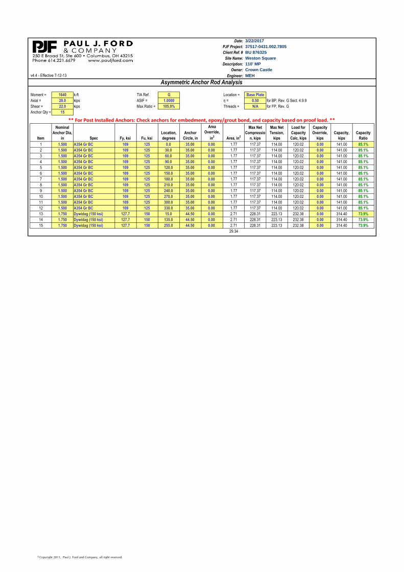
Date:
PJF Project:
Client Ref. #
Site Name:
Description:
Owner:
v4.4 - Effective 7-12-13 Engineer:
Moment = 1640 k-ft TIA Ref. G Location = Base Plate
Axial = 28.0 kips ASIF = 1.0000 η = 0.50 for BP, Rev. G Sect. 4.9.9
Shear = 22.0 kips Max Ratio = 105.0% Threads = N/A for FP, Rev. G
Anchor Qty = 15
Item
Nominal
Anchor Dia,
in Spec Fy, ksi Fu, ksi
Location,
degrees
Anchor
Circle, in
Area
Override,
in2
Area, in2
Max Net
Compressio
n, kips
Max Net
Tension,
kips
Load for
Capacity
Calc, kips
Capacity
Override,
kips
Capacity,
kips
Capacity
Ratio
1 1.500 A354 Gr BC 109 125 0.0 35.00 0.00 1.77 117.37 114.00 120.02 0.00 141.00 85.1%
2 1.500 A354 Gr BC 109 125 30.0 35.00 0.00 1.77 117.37 114.00 120.02 0.00 141.00 85.1%
3 1.500 A354 Gr BC 109 125 60.0 35.00 0.00 1.77 117.37 114.00 120.02 0.00 141.00 85.1%
4 1.500 A354 Gr BC 109 125 90.0 35.00 0.00 1.77 117.37 114.00 120.02 0.00 141.00 85.1%
5 1.500 A354 Gr BC 109 125 120.0 35.00 0.00 1.77 117.37 114.00 120.02 0.00 141.00 85.1%
6 1.500 A354 Gr BC 109 125 150.0 35.00 0.00 1.77 117.37 114.00 120.02 0.00 141.00 85.1%
7 1.500 A354 Gr BC 109 125 180.0 35.00 0.00 1.77 117.37 114.00 120.02 0.00 141.00 85.1%
8 1.500 A354 Gr BC 109 125 210.0 35.00 0.00 1.77 117.37 114.00 120.02 0.00 141.00 85.1%
9 1.500 A354 Gr BC 109 125 240.0 35.00 0.00 1.77 117.37 114.00 120.02 0.00 141.00 85.1%
10 1.500 A354 Gr BC 109 125 270.0 35.00 0.00 1.77 117.37 114.00 120.02 0.00 141.00 85.1%
11 1.500 A354 Gr BC 109 125 300.0 35.00 0.00 1.77 117.37 114.00 120.02 0.00 141.00 85.1%
12 1.500 A354 Gr BC 109 125 330.0 35.00 0.00 1.77 117.37 114.00 120.02 0.00 141.00 85.1%
13 1.750 Dywidag (150 ksi) 127.7 150 15.0 44.50 0.00 2.71 228.31 223.13 232.38 0.00 314.40 73.9%
14 1.750 Dywidag (150 ksi) 127.7 150 135.0 44.50 0.00 2.71 228.31 223.13 232.38 0.00 314.40 73.9%
15 1.750 Dywidag (150 ksi) 127.7 150 255.0 44.50 0.00 2.71 228.31 223.13 232.38 0.00 314.40 73.9%
29.34
Asymmetric Anchor Rod Analysis
110' MP
Crown Castle
MEH
** For Post Installed Anchors: Check anchors for embedment, epoxy/grout bond, and capacity based on proof load. **
3/22/2017
37517-0431.002.7805
BU 876325
Weston Square
© Copyright 2011, Paul J. Ford and Company, all right reserved.
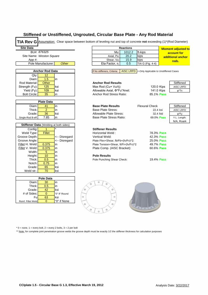
TIA Rev G
Site Data
BU#: 1012.2 ft-kipsSite Name: 20.2 kips
App #: 15.9 kipsOther Eta Factor, η 0.5 TIA G (Fig. 4-4)
If No stiffeners, Criteria: AISC LRFD <-Only Applcable to Unstiffened Cases
Qty: 12Diam: 1.5 in
Rod Material: Other Anchor Rod Results StiffenedStrength (Fu): 125 ksi Max Rod (Cu+ Vu/ή): 120.0 Kips AISC LRFD
Yield (Fy): 109 ksi Allowable Axial, Φ*Fu*Anet: 141.0 Kips φ*Tn
Bolt Circle: 35 in Anchor Rod Stress Ratio: 85.1% Pass
Diam: 41 in Base Plate Results Flexural Check StiffenedThick: 2 in Base Plate Stress: 22.4 ksi AISC LRFD
Grade: 36 ksi Allowable Plate Stress: 32.4 ksi φ*Fy
Single-Rod B-eff: 7.85 in Base Plate Stress Ratio: 69.0% Pass Y.L. Length:
N/A, Roark
Config: 1 * Stiffener ResultsWeld Type: Fillet Horizontal Weld : 78.3% Pass
Groove Depth: <-- Disregard Vertical Weld: 42.3% PassGroove Angle: <-- Disregard Plate Flex+Shear, fb/Fb+(fv/Fv)^2: 25.0% PassFillet H. Weld: 0.375 in Plate Tension+Shear, ft/Ft+(fv/Fv)^2: 49.7% PassFillet V. Weld: 0.375 in Plate Comp. (AISC Bracket): 60.6% Pass
Width: 5 in
Height: 10 in Pole ResultsThick: 0.5 in Pole Punching Shear Check: 19.4% PassNotch: 0.75 in
Grade: 65 ksiWeld str.: 70 ksi
Diam: 30 in
Thick: 0.5 inGrade: 42 ksi
# of Sides: 0 "0" IF Round
Fu 63 ksiReinf. Fillet Weld 0 "0" if None
* 0 = none, 1 = every bolt, 2 = every 2 bolts, 3 = 2 per bolt
** Note: for complete joint penetration groove welds the groove depth must be exactly 1/2 the stiffener thickness for calculation purposes
Assumption: Clear space between bottom of leveling nut and top of concrete not exceeding (1)*(Rod Diameter)
Stiffened or Unstiffened, Ungrouted, Circular Base Plate - Any Rod Material
Pole Data
Anchor Rod Data
Plate Data
Reactions
Stiffener Data (Welding at both sides)
876325 Mu:Axial, Pu:
Shear, Vu:
Weston Square
Pole Manufacturer:
Moment adjusted toaccount for
additional anchorrods.
CCIplate 1.5 - Circular Base G 1.3, Effective March 19, 2012 Analysis Date: 3/22/2017
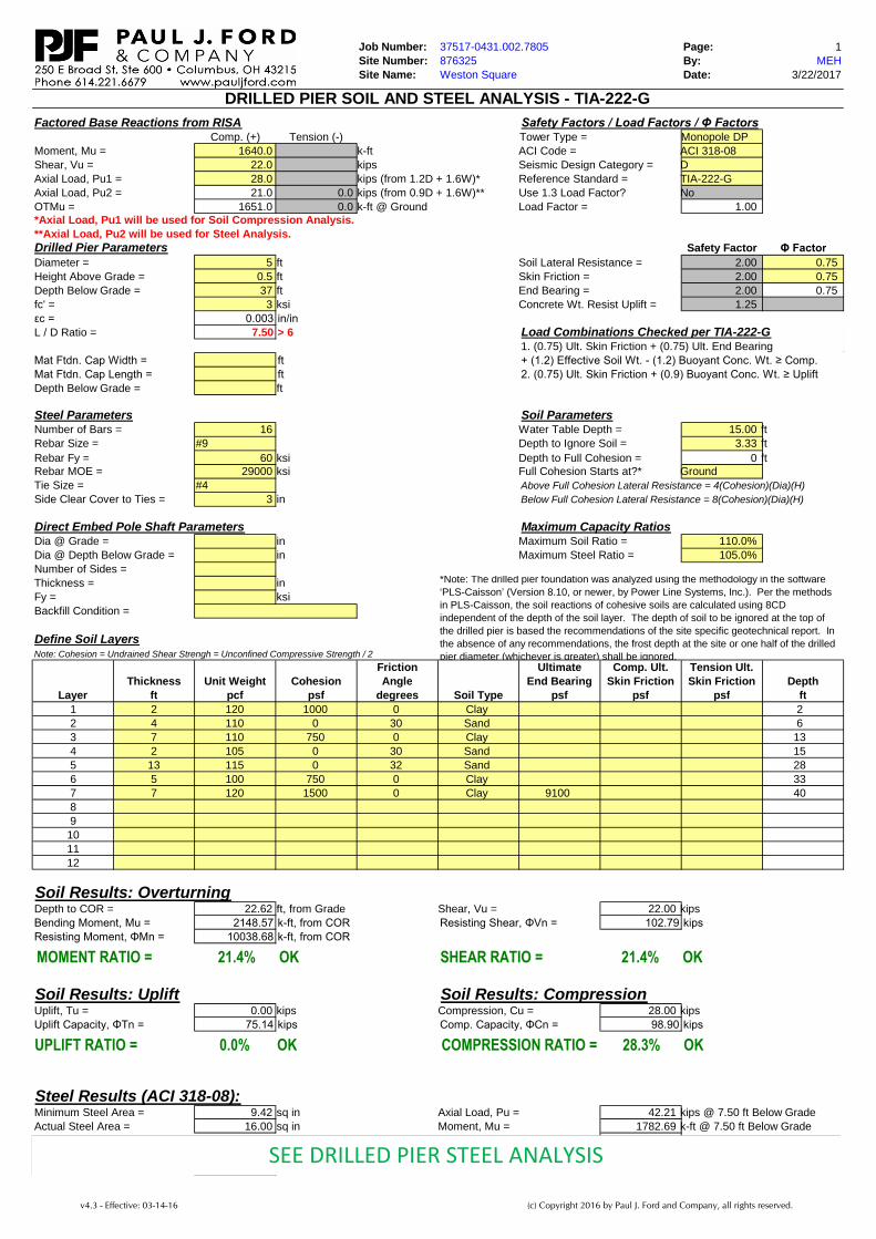
Job Number: 37517-0431.002.7805 Page: 1
Site Number: 876325 By: MEH
Site Name: Weston Square Date: 3/22/2017
Factored Base Reactions from RISA Safety Factors / Load Factors / Φ FactorsComp. (+) Tension (-) Tower Type = Monopole DP
Moment, Mu = 1640.0 k-ft ACI Code = ACI 318-08
Shear, Vu = 22.0 kips Seismic Design Category = D
Axial Load, Pu1 = 28.0 kips (from 1.2D + 1.6W)* Reference Standard = TIA-222-G
Axial Load, Pu2 = 21.0 0.0 kips (from 0.9D + 1.6W)** Use 1.3 Load Factor? No
OTMu = 1651.0 0.0 k-ft @ Ground Load Factor = 1.00*Axial Load, Pu1 will be used for Soil Compression Analysis.
**Axial Load, Pu2 will be used for Steel Analysis.
Drilled Pier Parameters Safety Factor Φ Factor
Diameter = 5 ft Soil Lateral Resistance = 2.00 0.75
Height Above Grade = 0.5 ft Skin Friction = 2.00 0.75
Depth Below Grade = 37 ft End Bearing = 2.00 0.75
fc' = 3 ksi Concrete Wt. Resist Uplift = 1.25
εc = 0.003 in/in
L / D Ratio = 7.50 > 6 Load Combinations Checked per TIA-222-G1. (0.75) Ult. Skin Friction + (0.75) Ult. End Bearing
Mat Ftdn. Cap Width = ft + (1.2) Effective Soil Wt. - (1.2) Buoyant Conc. Wt. ≥ Comp.
Mat Ftdn. Cap Length = ft 2. (0.75) Ult. Skin Friction + (0.9) Buoyant Conc. Wt. ≥ Uplift
Depth Below Grade = ft
Steel Parameters Soil ParametersNumber of Bars = 16 Water Table Depth = 15.00 ft
Rebar Size = #9 Depth to Ignore Soil = 3.33 ft
Rebar Fy = 60 ksi Depth to Full Cohesion = 0 ftRebar MOE = 29000 ksi Full Cohesion Starts at?* Ground
Tie Size = #4 Above Full Cohesion Lateral Resistance = 4(Cohesion)(Dia)(H)
Side Clear Cover to Ties = 3 in Below Full Cohesion Lateral Resistance = 8(Cohesion)(Dia)(H)
Direct Embed Pole Shaft Parameters Maximum Capacity RatiosDia @ Grade = in Maximum Soil Ratio = 110.0%
Dia @ Depth Below Grade = in Maximum Steel Ratio = 105.0%
Number of Sides =
Thickness = in
Fy = ksi
Backfill Condition =
Define Soil LayersNote: Cohesion = Undrained Shear Strengh = Unconfined Compressive Strength / 2
Friction Ultimate Comp. Ult. Tension Ult.
Thickness Unit Weight Cohesion Angle End Bearing Skin Friction Skin Friction Depth
Layer ft pcf psf degrees Soil Type psf psf psf ft
1 2 120 1000 0 Clay 2
2 4 110 0 30 Sand 6
3 7 110 750 0 Clay 13
4 2 105 0 30 Sand 15
5 13 115 0 32 Sand 28
6 5 100 750 0 Clay 33
7 7 120 1500 0 Clay 9100 40
8
9
10
11
12
Soil Results: OverturningDepth to COR = 22.62 ft, from Grade Shear, Vu = 22.00 kips
Bending Moment, Mu = 2148.57 k-ft, from COR Resisting Shear, ΦVn = 102.79 kips
Resisting Moment, ΦMn = 10038.68 k-ft, from COR
Soil Results: Uplift Soil Results: CompressionUplift, Tu = 0.00 kips Compression, Cu = 28.00 kips
Uplift Capacity, ΦTn = 75.14 kips Comp. Capacity, ΦCn = 98.90 kips
Steel Results (ACI 318-08):Minimum Steel Area = 9.42 sq in Axial Load, Pu = 42.21 kips @ 7.50 ft Below Grade
Actual Steel Area = 16.00 sq in Moment, Mu = 1782.69 k-ft @ 7.50 ft Below Grade
Moment, ΦMn = 1833.55 k-ft
Axial, ΦPn (min) = -864.00 kips, Where ΦMn = 0 k-ft
Axial, ΦPn (max) = 4227.16 kips, Where ΦMn = 0 k-ftMOMENT RATIO = 97.2% OK
OKCOMPRESSION RATIO = 28.3%
DRILLED PIER SOIL AND STEEL ANALYSIS - TIA-222-G
SHEAR RATIO = 21.4% OKMOMENT RATIO = 21.4% OK
*Note: The drilled pier foundation was analyzed using the methodology in the software
‘PLS-Caisson’ (Version 8.10, or newer, by Power Line Systems, Inc.). Per the methods
in PLS-Caisson, the soil reactions of cohesive soils are calculated using 8CD
independent of the depth of the soil layer. The depth of soil to be ignored at the top of
the drilled pier is based the recommendations of the site specific geotechnical report. In
the absence of any recommendations, the frost depth at the site or one half of the drilled
pier diameter (whichever is greater) shall be ignored.
UPLIFT RATIO = 0.0% OK
SEE DRILLED PIER STEEL ANALYSIS
v4.3 - Effective: 03-14-16 (c) Copyright 2016 by Paul J. Ford and Company, all rights reserved.
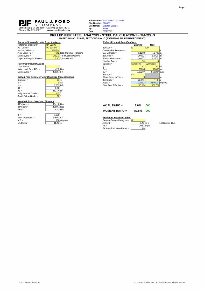
Page: 1
Job Number: 37517-0431.002.7805
Site Number: 876325
Site Name: Weston Square
By: MEH
Date: 3/22/2017
Factored Internal Loads from Analysis Rebar Size and SpecificationsReference Standard = TIA-222-G Existing New
ACI Code = ACI 318-08 Bar Size = #9 #10
Maximum Ratio = 105.0% Override Bar Diameter = inAxial Load, Pu = 42.2 kips, (+Comp, -Tension) Bar Diameter = 1.1280 1.2700 in
Moment, Mu = 1782.7 k-ft (Must be Positive) Bar Area = 1.0000 1.2700 in2
Depth to Analysis Section = 7.50 ft, from Grade Effective Bar Area = 1.0000 1.2700 in2
Number Bars = 16 3
Factored Internal Loads Spacing = Symmetric Symmetric
Load Factor = 1.0 fy = 60 60 ksi
Axial Load, Pu = ΦPn = 42.2 kips Es = 29000 29000 ksi
Moment, Mu = 1782.7 k-ft εy = 0.00207 0.00207 in/in
Tie Size = #4Drilled Pier Geometry and Concrete Specifications Clear Cover to Ties = 3 in
Diameter = 60 in Bar Circle = 51.872 44.5 in
fc' = 3 ksi Adjust = 11.2500 135.0000 degrees
εc = 0.003 in/in % of Area Effective = 100.0% 100.0%
β1 = 0.85
Ag = 2827.4 in2
Height Above Grade = 0.5 ft
Depth Below Grade = 37 ft
Nominal Axial Load and MomentΦPn(max) = 4341.0 kips
ΦPn(min) = -1069.7 kips
ΦPn = 42.2 kips
Φ = 0.900
ΦMn (Resultant) = 2160.7 k-ft Minimum Required Steelat θ = 180 degrees Seismic Design Category = D
NA Depth = 11.42 in As(min) = 9.42 sq in ACI Section 10.5
As = 19.81 sq in
Φ = Stl Area Reduction Factor = 1.00
ΦMn (Resultant) = k-ft
at θ = degrees
NA Depth = in
DRILLED PIER STEEL ANALYSIS - STEEL CALCULATIONS - TIA-222-G
MOMENT RATIO =
BASED ON ACI 318-08, SECTIONS 9 & 10 (ASSUMING TIE REINFORCEMENT)
82.5%
AXIAL RATIO = 1.0%
OK
OK
v1.0 - Effective: 01-05-2015 (c) Copyright 2015 by Paul J. Ford and Company, all rights reserved.
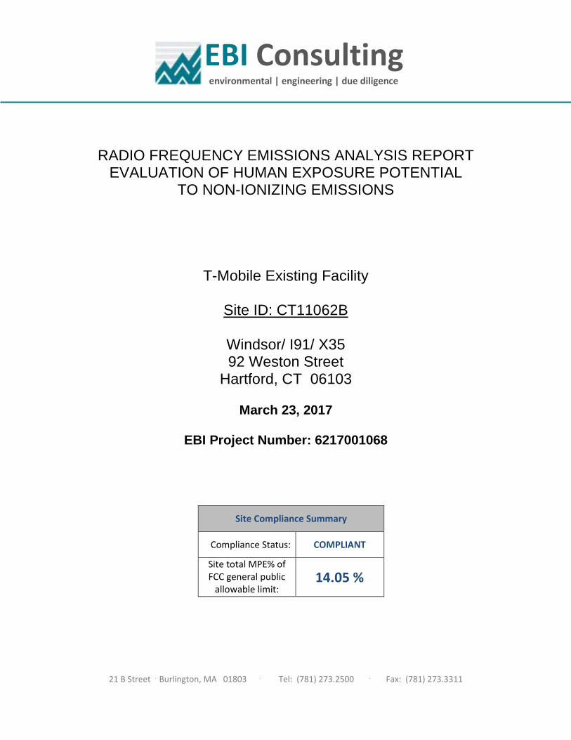
EBI Consulting environmental | engineering | due diligence
21 B Street . Burlington, MA 01803 . Tel: (781) 273.2500 . Fax: (781) 273.3311
RADIO FREQUENCY EMISSIONS ANALYSIS REPORT EVALUATION OF HUMAN EXPOSURE POTENTIAL
TO NON-IONIZING EMISSIONS
T-Mobile Existing Facility
Site ID: CT11062B
Windsor/ I91/ X35 92 Weston Street
Hartford, CT 06103
March 23, 2017
EBI Project Number: 6217001068
Site Compliance Summary
Compliance Status: COMPLIANT
Site total MPE% of FCC general public
allowable limit: 14.05 %
EBI Consulting environmental | engineering | due diligence
21 B Street . Burlington, MA 01803 . Tel: (781) 273.2500 . Fax: (781) 273.3311
March 23, 2017
T-Mobile USA Attn: Jason Overbey, RF Manager 35 Griffin Road South Bloomfield, CT 06002
Emissions Analysis for Site: CT11062B – Windsor/ I91/ X35
EBI Consulting was directed to analyze the proposed T-Mobile facility located at 92 Weston Street, Hartford, CT, for the purpose of determining whether the emissions from the Proposed T-Mobile Antenna Installation located on this property are within specified federal limits.
All information used in this report was analyzed as a percentage of current Maximum Permissible Exposure (% MPE) as listed in the FCC OET Bulletin 65 Edition 97-01and ANSI/IEEE Std C95.1. The
FCC regulates Maximum Permissible Exposure in units of microwatts per square centimeter (µW/cm2).
The number of µW/cm2 calculated at each sample point is called the power density. The exposure limit for power density varies depending upon the frequencies being utilized. Wireless Carriers and Paging Services use different frequency bands each with different exposure limits, therefore it is necessary to report results and limits in terms of percent MPE rather than power density.
All results were compared to the FCC (Federal Communications Commission) radio frequency exposure rules, 47 CFR 1.1307(b)(1) – (b)(3), to determine compliance with the Maximum Permissible Exposure (MPE) limits for General Population/Uncontrolled environments as defined below.
General population/uncontrolled exposure limits apply to situations in which the general public may be exposed or in which persons who are exposed as a consequence of their employment may not be made fully aware of the potential for exposure or cannot exercise control over their exposure. Therefore, members of the general public would always be considered under this category when exposure is not employment related, for example, in the case of a telecommunications tower that exposes persons in a nearby residential area.
Public exposure to radio frequencies is regulated and enforced in units of microwatts per square centimeter (μW/cm2). The general population exposure limit for the 700 MHz Band is approximately 467 μW/cm2, and the general population exposure limit for the 1900 MHz (PCS) and 2100 MHz (AWS) bands is 1000 μW/cm2. Because each carrier will be using different frequency bands, and each frequency band has different exposure limits, it is necessary to report percent of MPE rather than power density.
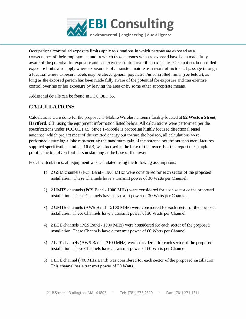
EBI Consulting environmental | engineering | due diligence
21 B Street . Burlington, MA 01803 . Tel: (781) 273.2500 . Fax: (781) 273.3311
Occupational/controlled exposure limits apply to situations in which persons are exposed as a consequence of their employment and in which those persons who are exposed have been made fully aware of the potential for exposure and can exercise control over their exposure. Occupational/controlled exposure limits also apply where exposure is of a transient nature as a result of incidental passage through a location where exposure levels may be above general population/uncontrolled limits (see below), as long as the exposed person has been made fully aware of the potential for exposure and can exercise control over his or her exposure by leaving the area or by some other appropriate means.
Additional details can be found in FCC OET 65.
CALCULATIONS
Calculations were done for the proposed T-Mobile Wireless antenna facility located at 92 Weston Street, Hartford, CT, using the equipment information listed below. All calculations were performed per the specifications under FCC OET 65. Since T-Mobile is proposing highly focused directional panel antennas, which project most of the emitted energy out toward the horizon, all calculations were performed assuming a lobe representing the maximum gain of the antenna per the antenna manufactures supplied specifications, minus 10 dB, was focused at the base of the tower. For this report the sample point is the top of a 6-foot person standing at the base of the tower.
For all calculations, all equipment was calculated using the following assumptions:
1) 2 GSM channels (PCS Band - 1900 MHz) were considered for each sector of the proposed installation. These Channels have a transmit power of 30 Watts per Channel.
2) 2 UMTS channels (PCS Band - 1900 MHz) were considered for each sector of the proposed installation. These Channels have a transmit power of 30 Watts per Channel.
3) 2 UMTS channels (AWS Band – 2100 MHz) were considered for each sector of the proposed installation. These Channels have a transmit power of 30 Watts per Channel.
4) 2 LTE channels (PCS Band - 1900 MHz) were considered for each sector of the proposed
installation. These Channels have a transmit power of 60 Watts per Channel. 5) 2 LTE channels (AWS Band – 2100 MHz) were considered for each sector of the proposed
installation. These Channels have a transmit power of 60 Watts per Channel 6) 1 LTE channel (700 MHz Band) was considered for each sector of the proposed installation.
This channel has a transmit power of 30 Watts.

EBI Consulting environmental | engineering | due diligence
21 B Street . Burlington, MA 01803 . Tel: (781) 273.2500 . Fax: (781) 273.3311
7) Since all 2100 MHz UMTS radios are ground mounted there are additional cabling losses accounted for. For each ground mounted 2100 MHz UMTS RF path an additional 1.73 dB of cable loss was factored into the calculations used for this analysis. This is based on manufacturers Specifications for 100 feet of 7/8” coax cable on each path.
8) All radios at the proposed installation were considered to be running at full power and were
uncombined in their RF transmissions paths per carrier prescribed configuration. Per FCC OET Bulletin No. 65 - Edition 97-01 recommendations to achieve the maximum anticipated value at each sample point, all power levels emitting from the proposed antenna installation are increased by a factor of 2.56 to account for possible in-phase reflections from the surrounding environment. This is rarely the case, and if so, is never continuous.
9) For the following calculations the sample point was the top of a 6-foot person standing at the base of the tower. The maximum gain of the antenna per the antenna manufactures supplied specifications minus 10 dB was used in this direction. This value is a very conservative estimate as gain reductions for these particular antennas are typically much higher in this direction.
10) The antennas used in this modeling are the Ericsson AIR32 B2A/B66Aa & Ericsson AIR21 B2A/B4P for 1900 MHz (PCS) and 2100 MHz (AWS) channels and the Commscope LNX-6515DS-A1M for 700 MHz channels. This is based on feedback from the carrier with regards to anticipated antenna selection. The Ericsson AIR32 B2A/B66Aa has a maximum gain of 15.9 dBd at its main lobe at 1900 MHz and 2100 MHz. The Ericsson AIR21 B2A/B4P has a maximum gain of 15.9 dBd at its main lobe at 1900 MHz and 2100 MHz. The Commscope LNX-6515DS-A1M has a maximum gain of 14.6 dBd at its main lobe at 700 MHz. The maximum gain of the antenna per the antenna manufactures supplied specifications, minus 10 dB, was used for all calculations. This value is a very conservative estimate as gain reductions for these particular antennas are typically much higher in this direction.
11) The antenna mounting height centerline of the proposed antennas is 76 feet above ground
level (AGL). 12) Emissions values for additional carriers were taken from the Connecticut Siting Council
active database. Values in this database are provided by the individual carriers themselves. 13) All calculations were done with respect to uncontrolled / general public threshold limits.
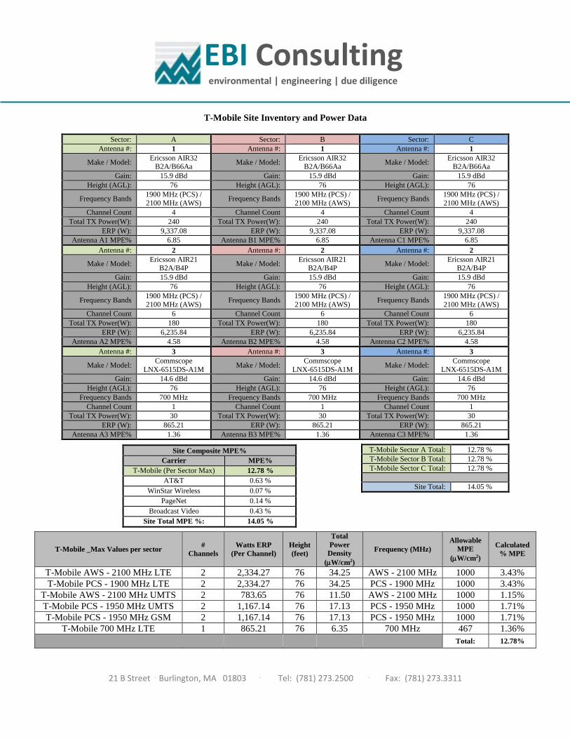
EBI Consulting environmental | engineering | due diligence
21 B Street . Burlington, MA 01803 . Tel: (781) 273.2500 . Fax: (781) 273.3311
T-Mobile Site Inventory and Power Data
Sector: A Sector: B Sector: C Antenna #: 1 Antenna #: 1 Antenna #: 1
Make / Model: Ericsson AIR32
B2A/B66Aa Make / Model:
Ericsson AIR32 B2A/B66Aa
Make / Model: Ericsson AIR32
B2A/B66Aa Gain: 15.9 dBd Gain: 15.9 dBd Gain: 15.9 dBd
Height (AGL): 76 Height (AGL): 76 Height (AGL): 76
Frequency Bands 1900 MHz (PCS) / 2100 MHz (AWS)
Frequency Bands 1900 MHz (PCS) / 2100 MHz (AWS)
Frequency Bands 1900 MHz (PCS) / 2100 MHz (AWS)
Channel Count 4 Channel Count 4 Channel Count 4 Total TX Power(W): 240 Total TX Power(W): 240 Total TX Power(W): 240
ERP (W): 9,337.08 ERP (W): 9,337.08 ERP (W): 9,337.08 Antenna A1 MPE% 6.85 Antenna B1 MPE% 6.85 Antenna C1 MPE% 6.85
Antenna #: 2 Antenna #: 2 Antenna #: 2
Make / Model: Ericsson AIR21
B2A/B4P Make / Model:
Ericsson AIR21 B2A/B4P
Make / Model: Ericsson AIR21
B2A/B4P Gain: 15.9 dBd Gain: 15.9 dBd Gain: 15.9 dBd
Height (AGL): 76 Height (AGL): 76 Height (AGL): 76
Frequency Bands 1900 MHz (PCS) / 2100 MHz (AWS)
Frequency Bands 1900 MHz (PCS) / 2100 MHz (AWS)
Frequency Bands 1900 MHz (PCS) / 2100 MHz (AWS)
Channel Count 6 Channel Count 6 Channel Count 6 Total TX Power(W): 180 Total TX Power(W): 180 Total TX Power(W): 180
ERP (W): 6,235.84 ERP (W): 6,235.84 ERP (W): 6,235.84 Antenna A2 MPE% 4.58 Antenna B2 MPE% 4.58 Antenna C2 MPE% 4.58
Antenna #: 3 Antenna #: 3 Antenna #: 3
Make / Model: Commscope
LNX-6515DS-A1M Make / Model:
Commscope LNX-6515DS-A1M
Make / Model: Commscope
LNX-6515DS-A1M Gain: 14.6 dBd Gain: 14.6 dBd Gain: 14.6 dBd
Height (AGL): 76 Height (AGL): 76 Height (AGL): 76 Frequency Bands 700 MHz Frequency Bands 700 MHz Frequency Bands 700 MHz
Channel Count 1 Channel Count 1 Channel Count 1 Total TX Power(W): 30 Total TX Power(W): 30 Total TX Power(W): 30
ERP (W): 865.21 ERP (W): 865.21 ERP (W): 865.21 Antenna A3 MPE% 1.36 Antenna B3 MPE% 1.36 Antenna C3 MPE% 1.36
Site Composite MPE% Carrier MPE%
T-Mobile (Per Sector Max) 12.78 % AT&T 0.63 %
WinStar Wireless 0.07 % PageNet 0.14 %
Broadcast Video 0.43 % Site Total MPE %: 14.05 %
T-Mobile Sector A Total: 12.78 % T-Mobile Sector B Total: 12.78 % T-Mobile Sector C Total: 12.78 %
Site Total: 14.05 %
T-Mobile _Max Values per sector #
Channels Watts ERP
(Per Channel) Height (feet)
Total Power
Density (µW/cm2)
Frequency (MHz) Allowable
MPE (µW/cm2)
Calculated % MPE
T-Mobile AWS - 2100 MHz LTE 2 2,334.27 76 34.25 AWS - 2100 MHz 1000 3.43% T-Mobile PCS - 1900 MHz LTE 2 2,334.27 76 34.25 PCS - 1900 MHz 1000 3.43%
T-Mobile AWS - 2100 MHz UMTS 2 783.65 76 11.50 AWS - 2100 MHz 1000 1.15% T-Mobile PCS - 1950 MHz UMTS 2 1,167.14 76 17.13 PCS - 1950 MHz 1000 1.71% T-Mobile PCS - 1950 MHz GSM 2 1,167.14 76 17.13 PCS - 1950 MHz 1000 1.71%
T-Mobile 700 MHz LTE 1 865.21 76 6.35 700 MHz 467 1.36% Total: 12.78%
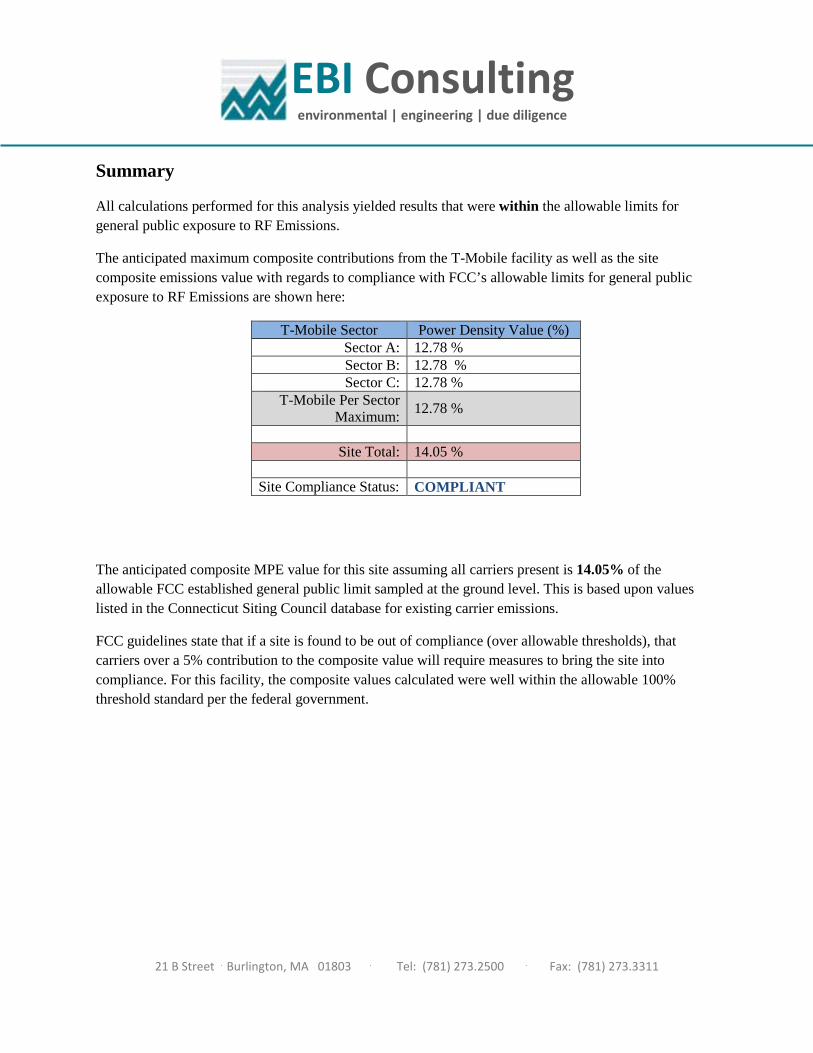
EBI Consulting environmental | engineering | due diligence
21 B Street . Burlington, MA 01803 . Tel: (781) 273.2500 . Fax: (781) 273.3311
Summary
All calculations performed for this analysis yielded results that were within the allowable limits for general public exposure to RF Emissions.
The anticipated maximum composite contributions from the T-Mobile facility as well as the site composite emissions value with regards to compliance with FCC’s allowable limits for general public exposure to RF Emissions are shown here:
T-Mobile Sector Power Density Value (%) Sector A: 12.78 % Sector B: 12.78 % Sector C: 12.78 %
T-Mobile Per Sector Maximum:
12.78 %
Site Total: 14.05 %
Site Compliance Status: COMPLIANT
The anticipated composite MPE value for this site assuming all carriers present is 14.05% of the allowable FCC established general public limit sampled at the ground level. This is based upon values listed in the Connecticut Siting Council database for existing carrier emissions.
FCC guidelines state that if a site is found to be out of compliance (over allowable thresholds), that carriers over a 5% contribution to the composite value will require measures to bring the site into compliance. For this facility, the composite values calculated were well within the allowable 100% threshold standard per the federal government.