Embed Size (px)
Citation preview

Suite 180012700 Park Central DriveDallas, Texas75251
TEL 972 770 1300FAX 972 239 3820
February 1, 2007
City of Dallas, Texas1500 Marilla, Room 4ANDallas, Texas 75201Attention: Jody Puckett, PE, Director, Dallas Water Utilities Rick Galceran, PE, Asst. Director Dallas Water Utilities Charles Stringer, PE, Asst. Director Dallas Water Utilities Erling Holey, PE, Section Manager, Dallas Water Utilities Ben Stephenson, PE, Section Manager, Dallas Water Utilities
Re: Dallas Logistics HubMaster Water Plan UpdateCity of Dallas, Texas
Dear Ms. Puckett:
On behalf of Allen Development of Texas, LLC (TAG), Kimley-Horn and Associates, Inc.(KHA) has performed water service network planning for the proposed Dallas Logistics Hub(DLH) development located in the Cities of Dallas, Hutchins, Lancaster, and Wilmer, Texas.The purpose of this work is to establish adequate levels of water service for the development,identify the improvements necessary for this level of service, and further the intended goal ofadding value to all four communities. This submittal includes a detailed summary of themethodology behind the proposed water plan, the design criteria and water demandcalculations utilized, an analysis of the water system needs created by the Dallas LogisticsHub, and accompanying exhibits. Per the City’s request, this information is being submittedfor inclusion in the City’s master water plan.
MethodologyIn order to analyze and evaluate the existing and proposed water systems, a computer modelwas created using WaterCAD for Autodesk Land Desktop 2004. The hydraulic modelingand analysis relied on a computer program that solves large sets of simultaneous non-linearequations representing hydraulic and geometric characteristics of the pipe network.Information required included pipes, ground storage tanks, elevated storage tanks, pumpstations, and node data. Pipe data consisted of pipe length, location, diameter, and theroughness coefficient of the pipe. Ground storage tanks (reservoirs) were the initial watersupply for the model and the data consisted of the initial hydraulic grade line. Elevatedstorage tank data consisted of the storage volume, overflow elevation, head range, and groundelevation. Pump station data consisted of ground elevations, number of pumps, pumpimpeller elevation, and pump curve data. Node data, identified as occurring at the connectionof two or more pipes, consisted of ground elevation and demand, with elevations determinedby topographic surveys and flow demands calculated in accordance with commonly accepteddesign criteria and jurisdictional agencies (City of Dallas’ Water and Wastewater PipelineDesign Manual and AWWA Manual of Water Supply Practices M32, Distribution NetworkAnalysis for Water Utilities). Using GIS (Geographic Information Systems) these nodes werethen used to split the entire site into theissen polygons, with one node per polygon.

Ms. Puckett, February 1, 2007, Pg. 2
G:\HYDRO\PROJECTS\64011004\Docs\City Submittals\Dallas\Dallas Water\Dallas-Water_20070201.doc
The overall land use map (Exhibit A-1) was created by combining the City’s current land useplan, the proposed DLH land use plan, and appropriate land uses for the existing tracts. “Gaps”occurring in the land uses were filled in by extending out the proposed land uses. These land useareas were then inserted into GIS and water demands were assigned to each land use area via ascript that was written specifically for the water demand assumptions for the DLH development.Pivot tables were created to determine the percentage of each land use within each theissenpolygon and the demand associated with each land use. An Excel spreadsheet was then used toadd up all of the demands within each polygon. The demands and ground elevations for eachnode were then exported out of GIS and into the proposed KHA WaterCAD model to be usedto determine flows, pipe sizes and storage. The determination of the pipe sizes for the proposedwater network was made by analysis of maximum day demand, fire flow, and peak hourconditions. By applying basic hydraulic principles and using criteria established by TCEQ,pipes were sized within the network to establish desirable operating characteristics. Using theWaterCAD model, these pipes were checked to verify that they could maintain suitable pressureand volume requirements for the maximum day condition and fire flow. If these criteria were notmet, the model was repeatedly adjusted and re-analyzed until satisfactory results were obtained.As part of the WaterCAD analysis, KHA obtained the City’s existing master water plan to verifythat the proposed water line sizes did meet pressure and volume requirements.
The factors to sizing the storage facilities relates to several considerations: equalization storage,fire storage and emergency storage. “Equalization storage is sized to carry demands in excessof the maximum day demand up to peak hour demand.” This is represented as the area underthe Peak Hour curve above the Maximum Day demand. In addition, “There should be enoughto furnish fire-flow requirements within the tank’s area of influence.” And finally, “The amountof emergency storage included within a particular water distribution system is an owner optionbased on an assessment of risk and the desired degree of system dependability.” (Source:AWWA M32, Distribution Network Analysis for Water Utilities)
The following criteria were used to size the storage facilities needed to serve the futuredevelopment:
Equalization storage = 25% of max day demand
Fire storage = 3500 GPM x 4 hours
Emergency storage = Average Daily Demand
Total Recommended Storage = Sum of the above
The total storage can be accomplished through a combination of ground and elevated facilities.Depending on the city’s operational preference and degree of system dependability desired it isrecommended that at least 30% of the ultimate City storage capacity be provided through elevatedstorage tanks. The DLH portion of the storage will be provided solely through ground storage tanks.
Design CriteriaBecause water demands for industrial and manufacturing facilities vary significantly and thereis not a generally accepted source for this land use, KHA referred to the following documentsto establish water (and sewer) flows. The design criteria utilized for this analysis is based onthe following sources:
- Wastewater Engineering by Metcalf & Eddy, Third Edition - Dallas Water Utilities Water & Wastewater Pipeline Design Manual, May 1998 - City of Hutchins Impact Fee Analysis for Water, Wastewater, Hunter Associates Texas, Ltd., December 2004

Ms. Puckett, February 1, 2007, Pg. 3
G:\HYDRO\PROJECTS\64011004\Docs\City Submittals\Dallas\Dallas Water\Dallas-Water_20070201.doc
Table 1: Water Design Flow Assumptions
Land UseAverage Flow
(gal / acre / day) Source Sewer Source
Airport 1,700 assume sewer rate with 90% return Metcalf & Eddy range 1000 - 3000 with judgment on use
Flex Space / Office 190 Hutchins Impact Fee Use Office Rate
Future Intermodal 1100 engineering judgment
Heavy Manufacturing / Open Storage 3,300 assume sewer rate with 90% return Metcalf & Eddy range 1000 - 3000 with judgment on use
Light Industrial Distribution 1,100 assume sewer rate with 90% return Metcalf & Eddy range 1000 - 3000 with judgment on use
Light Industrial Manufacturing 2,800 assume sewer rate with 90% return Metcalf & Eddy range 1000 - 3000 with judgment on use
Multi-Family Residential 4,000 Hutchins Impact Fee 90 gpcd x 2 persons /unit = 180 gpd/unit x 22 unit/ac
Neighborhood Commercial 960 Hutchins Impact Fee 80g/employee/d x 12 employee/ac
Open Space / Park 100 Hutchins Impact Fee Use Park Rate
Public Use 1,000 Hutchins Impact Fee Use School Rate
Rail Served Heavy Industrial 1,700 assume sewer rate with 90% return Metcalf & Eddy range 1000 - 3000 with judgment on use
Single Family Residential 1,209 Hutchins Impact Fee 130 gpcd x 3.1 persons/unit = 403 gpd x 3 unit/ac
Townhome Residential 2,400 Hutchins Impact Fee (assume 8 units / ac) 100 gpcd x 3.0 person/unit = 300 gpd x 8 unit/ac
Highway Commercial 360 Hutchins Impact Fee 40g/employee/d x 9 employee/ac
Corporate Center 190 Hutchins Impact Fee Use Office Rate
Campus Building Block 1,000 Hutchins Impact Fee Use School Rate
General Rail Served Heavy Industrial 1,700 assume sewer rate with 90% return Metcalf & Eddy range 1000 - 3000 with judgment on use
Airport Related Industrial 1,700 assume sewer rate with 90% return Metcalf & Eddy range 1000 - 3000 with judgment on use
Mobile Home 2,080 Hutchins Impact Fee 100 gpcd x 2.6 persons/unit = 260 g/unit x 8 unit/ac
Probation Center 2,700 Metcalf & Eddy (150 g/bed/day x 326 Beds)/18 acres
Retail 960 Hutchins Impact Fee Use Neighborhood Commercial Rate
Storm Water Detention 0 engineering judgment*Metcalf and Eddy sewer rates used for land uses not available from local sources. Water demand calculated assuming 90% return.

Ms. Puckett, February 1, 2007, Pg. 4
G:\HYDRO\PROJECTS\64011004\Docs\City Submittals\Dallas\Dallas Water\Dallas-Water_20070201.doc
In addition to the assumptions shown in Table 1, the following criteria were also used:
Fire Flow (residential) = 1,500 gpm
Fire Flow (industrial / non-residential) = 3,500 gpm
Max. Day = 2.4 x Avg. Day
Peak Hour = 1.25 x Max. Day
Hazen- Williams “C” factor = 110
Water Demand Flow Calculations
Since the City of Dallas is the water supplier to Hutchins and Lancaster and eventuallycould supply water to Wilmer this section will address demand flows under separateassumptions. Firstly, as the supply source for the other cities and secondly, for theproperties located within the Dallas city limits.
The proposed improvements to the other cities in the area will take additional planning bythe Dallas staff. Table 2 below shows the expected ultimate water uses for the cities thatservice the DLH.
Table 2: Ultimate Water Demands
City Average DayDemand (MGD)
Max Day Demand(MGD)
Peak HourDemand (MGD)
Lancaster * 11.6 27.9 34.8Hutchins 7.8 18.7 23.3Wilmer 13.1 30.8 38.6
TOTAL 32.5 77.4 96.7* 705 pressure zone only.
The current DWU model does not have demands of this magnitude. To meet this demand,additional planning by DWU will be required. Also, Lancaster currently has its consultantmaster planning their water system. The increased demands within the DLH has beenshared with them for inclusion in their study. It is anticipated that these studies willrequire additional trunk mains within the DLH. Once information is available,coordination between the cities’ staff will be incorporated in the future plans for theDLH.
Dallas Only Demands:
The ultimate average daily flow calculated for properties located within the study areaand the Dallas city limits using the described methodology is 4.1 MGD (million gallonsper day). This translates to a max day demand of 9.8 MGD and a peak hour demand of12.3 MGD.

Ms. Puckett, February 1, 2007, Pg. 5
G:\HYDRO\PROJECTS\64011004\Docs\City Submittals\Dallas\Dallas Water\Dallas-Water_20070201.doc
Table 3 identifies the basin demands and the Dallas Logistics contribution within thosebasins.
Table 3: Dallas Future Water Demands by BasinBasin Average
DailyMGD
DLHContribution
MaxDay
MGD
DLHContribution
PeakHourMGD
DLHContribution
D1 0.5 0.3 1.3 0.8 1.6 1.0D2 0.3 0.1 0.8 0.2 1.0 0.2D3 1.0 0.5 2.3 1.2 2.8 1.5D4 0.6 0.4 1.4 1.0 1.8 1.2D5 1.7 0.1 4.1 0.2 5.2 0.3
TOTAL 4.1 1.4 9.9 3.4 12.4 4.2
Water System Analysisa. Existing System Description
The City of Dallas serves the southeast portion of the city located in the Cedardale Highpressure zone through trunk lines ranging from 18” to 30”. This pressure zone is servedby the Alta Mesa Pump Station and the Cedardale 0.5 MG elevated storage tank. ExhibitA-2 shows the existing system. The pump station is currently under design for expansionfrom 2 to 20 MGD.
b. Existing Master Plan
The City of Dallas master utility plan includes the expansion of the Alta Mesa pumpstation along with the construction of a 300 MGD raw water treatment plant on propertycurrently owned in Hutchins. There are also 120” and 96” transmission lines proposed toserve this plant that originate at the Eastside Treatment plant in Mesquite and runs to theSorcey Pump Station in Grand Prairie. The alignment within the DLH for this line isgenerally along Telephone Road. These improvements are currently planned for 2015-2020. A copy of the Recommended Pipeline Alignment by TCB is included in theappendix as Exhibit A-3.
c. Results of Modeling
The water lines shown in Exhibit A-4 are sized to accommodate the proposeddevelopment and fire flows within the DLH and the city based on its current future landuse map. New 16” pipes are proposed with this submittal. Changes in the alignment ofthe water lines were made to match the proposed road network as shown within the DLHdevelopment.
d. Recommended Improvements
In accordance with the master water plan, a water network is proposed to serve theproperties located within the service area. These pipes are typically 16”. These pipesconnect to the existing 16” lines that run to a 30” line which then runs to the Alta MesaPump Station. These water line improvements along with the City’s proposed

Ms. Puckett, February 1, 2007, Pg. 6
G:\HYDRO\PROJECTS\64011004\Docs\City Submittals\Dallas\Dallas Water\Dallas-Water_20070201.doc
improvements at the Alta Mesa pump station, under design by Dallas, provide adequateservice for properties located within the Cedardalse High area of Dallas and the DLH.
The addition of the Southeast Raw Water Treatment Plant provides adequate supply forthe future service area, including the addition of the City of Wilmer as customer city. Thetiming of these improvements will need to be closely coordinated between the cities ofDallas, Hutchins, Lancaster, Wilmer and The Dallas Logistics Hub to allow the partiesinvolved flexibility as development occurs. Interim piping schemes will be proposed asdevelopment occurs until the treatment plant is put into operation. It is the goal of TAGand KHA that this interim piping be a part of the ultimate configuration as the City ofDallas develops.
ConclusionThe Dallas Logistics Hub and the City of Dallas are in a unique position to determinethe future growth of the DLH and the surrounding cities. Dallas Water Utilities is, or willbecome the water provider for the area. Additional planning by the city staff will berequired to determine the impact of the DLH development and the addition of the Cityof Wilmer to its master plan.
The current long-range plan for Dallas has several elements included that indicate it isready to accommodate the anticipated growth in the region. The proposed SoutheastWater Treatment Plant and corresponding transfer lines are being planned to meet thesedemands. This plant will provide an additional 300 MGD for the region. The timing ofthis construction and the associated infrastructure will determine the availability of waterfor the development within the DLH.
This letter has been written to request your review of our proposed water serviceimprovements and that any comments be returned to The Allen Group and Kimley-Hornand Associates, Inc. Once you are satisfied with the improvements proposed, this letterrequests approval and adoption of our findings as amendments to the current masterwater plan for Dallas. If you have any questions or comments regarding this request,please feel free to contact me at [email protected] or (972) 770-1300.
Very truly yours,
Kimley-Horn and Associates, Inc.
Len McManus, P.E.Project Manager
cc: Jason Elms, PE, Allen Development of Texas, LLCDan McAuliffe, Allen Development of Texas, LLC
Bill Dahlstrom, Jackson Walker, LLP
Attachments: Conceptual Land Use PlanProposed Water Distribution Plan

Dallas
AIRPORTLANCASTER
I-20
I-45BN
SF R
R
BELT LINE ROAD
HutchinsB
ON
NIE
VIE
W R
OAD
WINTERGREEN ROAD
Lancaster
ALTA MESAPUMPSTATION
16"
16"
16"
16"
16"
16"
16"
30"
30"
30"
12"
12"
12"
12"
12"
8"8"
8"
8"
8"
24"24
"
8"
6"
6"16"
12"8"
8"8"
8"16"
16"
24"
30"
72"
72"
16"
16"
CEDARDALEELEVATIONTANK
JULY 2007Exhibit A-2: Proposed Dallas Service Area
PROPOSED ROAD
CITY LIMIT LINES
LEGEND
CEDAR DALE HIGHSERVICE AREA
EXISTING WATER LINES16"


Suite 180012700 Park Central DriveDallas, Texas75251
TEL 972 770 1300FAX 972 239 3820
October 6, 2006
via FedEx
Dallas Water UtilitiesCity of Dallas2121 Main StreetSuite 500Dallas, Texas 75201
Attention: Mark Williams, Senior Project Coordinator
Re: Dallas Logistics HubWater Demand SummaryWater Service Options and RecommendationsRequest for Dallas Water Utilities Evaluation and Coordination
Dear Mark:
Thank you once again to you and the rest of the Dallas Water Utilities (DWU) Staff fortaking the time to meet with us back in August. The purpose of this letter is to report onthe referenced items and request review and further coordination.
On behalf of The Allen Group (TAG), Kimley-Horn and Associates, Inc. (KHA) hasperformed water demand studies for the proposed Dallas Logistics Hub (DLH)development located in the cities of Dallas, Hutchins, Lancaster, and Wilmer, Texas.While these studies are ongoing, we feel now is the time to share information concerningwater demand with DWU so to plan adequately for the DLH growth projections known atthis time. Exhibit A-1 shows the current Conceptual Land Use Plan for DLH.
With respect to current water demand by each current Customer City, DWU would haveavailable the most up to date information for the cities of Hutchins, Dallas, and Lancasterwithin the study area. For the City of Wilmer, KHA has researched their current demandby interviewing Earl Kendrick, Wilmer Water Superintendent. Wilmer’s maximum dailydemand is 0.55 MGD with an average daily demand of 0.29 MGD.
Dallas Water Utilities, October 6, 2006, Pg. 2
G:\HYDRO\PROJECTS\64011004\Docs\City Submittals\Dallas\Dallas Water\DLH_DWU_Demand_Memo.doc
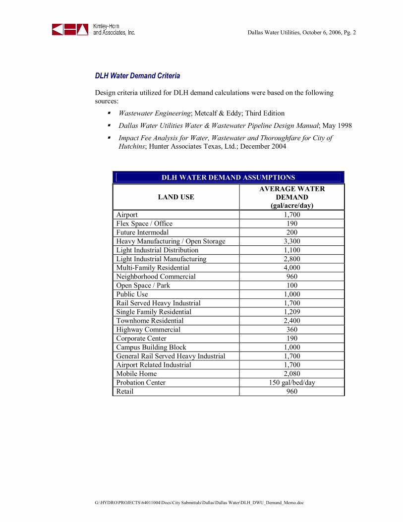
DLH Water Demand Criteria
Design criteria utilized for DLH demand calculations were based on the followingsources:
Wastewater Engineering; Metcalf & Eddy; Third Edition
Dallas Water Utilities Water & Wastewater Pipeline Design Manual; May 1998
Impact Fee Analysis for Water, Wastewater and Thoroughfare for City ofHutchins; Hunter Associates Texas, Ltd.; December 2004
DLH WATER DEMAND ASSUMPTIONS
LAND USEAVERAGE WATER
DEMAND(gal/acre/day)
Airport 1,700Flex Space / Office 190Future Intermodal 200Heavy Manufacturing / Open Storage 3,300Light Industrial Distribution 1,100Light Industrial Manufacturing 2,800Multi-Family Residential 4,000Neighborhood Commercial 960Open Space / Park 100Public Use 1,000Rail Served Heavy Industrial 1,700Single Family Residential 1,209Townhome Residential 2,400Highway Commercial 360Corporate Center 190Campus Building Block 1,000General Rail Served Heavy Industrial 1,700Airport Related Industrial 1,700Mobile Home 2,080Probation Center 150 gal/bed/dayRetail 960

Dallas Water Utilities, October 6, 2006, Pg. 3
G:\HYDRO\PROJECTS\64011004\Docs\City Submittals\Dallas\Dallas Water\DLH_DWU_Demand_Memo.doc
DLH Water Demand Projection
KHA performed a projection exercise to identify the incremental water demand of DLHproperties. TAG is currently working to project market demand for DLH properties, andthe results below reflect the results of that study available as of the date of this report.
The table below reports DLH development demand based on the uses identified withinthe DLH Conceptual Land Use Plan. DLH is projected to have a development timeframeover the next 25 years; therefore the demand table ends at year 2032. The average dailydemands above can be extrapolated to maximum daily demands by multiplying by 2.4, inaccordance with the referenced criteria. Attached to this report is a copy of our basedemand calculation spreadsheet used to generate the demands reported in the table below.
DLH FUTURE AVERAGE DAILY DEMAND (MGD) (5-YEAR PERIODS)YEAR
DALLAS HUTCHINS WILMER LANCASTER TOTAL CUMULATIVE
2007 0.05 0.45 0.00 0.21 0.71 0.71
2012 0.30 0.82 0.42 0.46 2.01 2.72
2017 0.38 0.71 0.67 0.55 2.31 5.03
2022 0.27 0.52 0.46 0.38 1.63 6.66
2027 0.24 0.25 0.36 0.81 1.67 8.33
2032 0.27 0.48 0.00 0.22 0.96 9.29TOTAL 1.51 3.24 1.91 2.64 9.29 9.29
Dallas Water Utilities, October 6, 2006, Pg. 4
G:\HYDRO\PROJECTS\64011004\Docs\City Submittals\Dallas\Dallas Water\DLH_DWU_Demand_Memo.doc
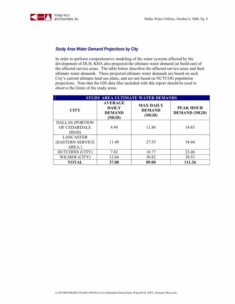
Study Area Water Demand Projections by City
In order to perform comprehensive modeling of the water systems affected by thedevelopment of DLH, KHA also projected the ultimate water demand (at build-out) ofthe affected service areas. The table below describes the affected service areas and theirultimate water demands. These projected ultimate water demands are based on eachCity’s current ultimate land use plans, and are not based on NCTCOG populationprojections. Note that the GIS data files included with this report should be used toobserve the limits of the study areas.
STUDY AREA ULTIMATE WATER DEMANDS
CITY
AVERAGEDAILY
DEMAND(MGD)
MAX DAILYDEMAND
(MGD)
PEAK HOURDEMAND (MGD)
DALLAS (PORTIONOF CEDARDALE
HIGH)4.94 11.86 14.83
LANCASTER(EASTERN SERVICE
AREA )11.48 27.55 34.44
HUTCHINS (CITY) 7.82 18.77 23.46WILMER (CITY) 12.84 30.82 38.53
TOTAL 37.08 89.00 111.26

Dallas Water Utilities, October 6, 2006, Pg. 5
G:\HYDRO\PROJECTS\64011004\Docs\City Submittals\Dallas\Dallas Water\DLH_DWU_Demand_Memo.doc
Conclusions, Options and Recommendations
The paragraphs below summarize KHA’s conclusions and options to date on a city by citybasis.
DallasKHA would like to work with DWU to prepare an addendum to the City's Water Master Plan toincorporate any modifications that may be necessary to serve DLH. We also see theopportunity to partner in the planning for the 96” and 120” transmission mains that will crossthe northern portion of DLH.
LancasterThe City of Lancaster is currently undergoing a revision to their Water Master Plan on a city-wide basis. KHA is preparing an addendum to the Water Master Plan to change main sizingand alignment and identify storage needs. As a current DWU customer, the City of Lancasterwould coordinate the future demands of DLH with DWU as growth occurs.
WilmerThe City of Wilmer currently receives its water via an emergency interconnect to DWUthrough the City of Hutchins. The attached DWU Potential Connections Exhibit shows asolution to bring DWU water to the City of Wilmer. This connection could be seen as a shortterm solution until DWU’s Southeast Water Treatment Plant (SEWTP) came online. Both ofthese potential connections to DWU would create the need for Wilmer to become a DWUCustomer City. KHA is also preparing an addendum to their Water Master Plan to changemain sizing and alignment and identify storage needs.
HutchinsHutchins is currently a DWU Customer City, with its single connection to DWU water alongSH 310 near IH20. The future SEWTP would be a primary DWU water source in the longterm. KHA has shown on the attached DWU Potential Connections Exhibit two potentialsecondary transmission connections from DWU facilities to Hutchins to create short termreliability. KHA is also preparing an addendum to Hutchins’ Water Master Plan to changemain sizing and alignment and identify storage needs.
Dallas Water Utilities, October 6, 2006, Pg. 6
G:\HYDRO\PROJECTS\64011004\Docs\City Submittals\Dallas\Dallas Water\DLH_DWU_Demand_Memo.doc
RecommendationsKHA is currently building the infrastructure plan for DLH, with water as a primary element.We’re working to identify not only infrastructure needs within DLH, but also to facilitateinfrastructure service to DLH. We appreciate DWU’s willingness to partner with us indeveloping this plan for development of one of the highest growth potential areas in the Dallas-Fort Worth Metroplex.
KHA respectfully requests that DWU Staff review the information contained in this report sothat we may reconvene and discuss DWU comments, recommendations, and alternatives for thetopics discussed.
If you have any questions or comments regarding this report or its contents, please do nothesitate to contact me or Len McManus at (972) 770-1300. We’ll be contacting you soon tofollow up.
Very truly yours,
Kimley-Horn and Associates, Inc.
Dan F. Grant, P.E.
Attachments: Water Demand Spreadsheet (digital and hard copy)DLH Conceptual Land Use PlanDWU Potential Connections ExhibitDigital GIS Files
cc: Charles Stringer, P.E., Assistant Director, DWU (letter only via email)Erling Holey, P.E., Manager, DWU (letter only via email)Ben Stephenson, P.E., Section Manager, DWU (letter only via email)Daniel J. McAuliffe, CCIM, Vice President of Development, The Allen Group (letteronly via email)Jason R. Elms, P.E., Director of Engineering, The Allen Group (letter only via email)Len McManus, P.E., Kimley-Horn and Associates, Inc.

Interstate Highway 45
Bon
nie
Vie
w R
oad
Langdon Road
D2
D1
D4
D5
D3
Dallas
16"
16"
16"
16"
16"
16"
16"
30"
30"
30"
12"
12"
12"
12"
12"
8"8"
8"
8"
8"
24"
24"
8"
6"
6"
16"12"
8"
8"8"
8"16"
16"
24"
Wintergreen Road
Existing Water Infrastructure - Dallas
CITY MASTERPLAN
LEGEND
GG
EE
AMENDMENTTO CITY
MASTER PLAN
8"
10"
12"
14"
18"
27"
30"
36"
24"
42"
6"
18"
14"
12"
10"
8"
6"6" WATER LINE
8" WATER LINE
10" WATER LINE
12" WATER LINE
14" WATER LINE
18" WATER LINE
27" WATER LINE
30" WATER LINE
36" WATER LINE
EXISTING
8"
10"
12"
14"
18"
27"
30"
36"
24"24" WATER LINE
24"
42" WATER LINE42"
30"
6"
27"
36"
42"
ELEVATEDSTORAGE
GROUNDSTORAGE
IDENTIFIERWATER AREA
DETAILED STUDY AREA
BASIN BOUNDARY
L11
MAY 2007

Interstate Highway 45
Bon
nie
Vie
w R
oad
Langdon Road
D2
D1
D4
D5
D3
Dallas
16"
16"
16"
16"
16"
16"
16"
16"
16"16
"
16"
16"
16"
16"
16"
16"
16"
30"
30"
30"
12"
12"
12"
12"
12"
8"8"
8"
8"
8"
24"
24"
8"
6"
6"
16"12"
8"
8"8"
8"16"
16"
24"
Wintergreen Road
Exhibit A-4: Proposed Water Master Plan AmendmentsJULY 2007
CITY MASTERPLAN
LEGEND
GG
EE
AMENDMENTTO CITY
MASTER PLAN
8"
10"
12"
14"
18"
27"
30"
36"
24"
42"
6"
18"
14"
12"
10"
8"
6"6" WATER LINE
8" WATER LINE
10" WATER LINE
12" WATER LINE
14" WATER LINE
18" WATER LINE
27" WATER LINE
30" WATER LINE
36" WATER LINE
EXISTING
8"
10"
12"
14"
18"
27"
30"
36"
24"24" WATER LINE
24"
42" WATER LINE42"
30"
6"
27"
36"
42"
ELEVATEDSTORAGE
GROUNDSTORAGE
IDENTIFIERWATER AREA
DETAILED STUDY AREA
BASIN BOUNDARY
L11