Embed Size (px)
Citation preview
ELI?.2.2 with effect from RDSO SPEC NO.December 2011 RDSO/PE/SPEC/AC/0061-2005 Rev-1
. GOVERNMENT OF INDIAMINISTRY OF RAILWAYS
~ ~~ 1{f[C/)Wwr
~mmRESEARCH DESIGNS AND STANDARDS ORGANISATION
MINISTRY OF RAILWAYS .•
~o ~o fro~ ~ 'ffl ~ ~ ~ ~ JjI\j)~\S ~ 'ffl ~ ~ tt ~SPECIFICATION FOR ROOF MOUNTED AC PACKAGE UNIT
FORLHBVA~ANTACCOACHES31Nt)~'tIaTI/~;m/~/0061-2005(ftcfio-1)
RDSO/PE/SPEC/AC/0061- 2005 - (REV. 1)
S.No Date of Revision! Reasonamendment Amendment
1 Dec. 2011 Rev. 1 Specification of microprocessor controllerseparated, Servo drive, solenoid valve, capillarytubes, hot gas bypass system removed andother imoroved features incoroorated.
\~3lj~1 (j
APPROV~D....1" n~,~ __
\'1-.\1-.",
~~/t~~~~<LED/PS & EMU
I Prepared by I Checked by
Page 2 of 51 ELn.2.2 with effect from RDSO SPEC NO.December 2011 RDSO/PE/SPEC/AC/0061-2005
(Rev-1)
SPECIFICATION FOR ROOF MOUNTED AC PACKAGE UNITFOR LHB VARIANT AC COACHES
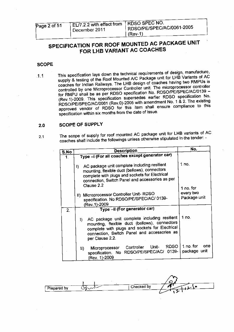
.1.1 This specification lays down the technical requirements of design, manufacture,supply & testing of the Roof Mounted AlC Package unit for LHB Variants of ACcoaches for Indian Railways. The LHB design of coaches haVing two RMPUs iscontrolled by one Microprocessor Controller unit. The microprocessor controllerfor RMPU shall be as per ROSO specification No. ROSO/PE/SPEC/AC/0139 -(Rev. 1)-2009. This specification supersedes earlier ROSO specification No.ROSO/PE/SPEC/AC/0061 (Rev.0)-2005 with amendment No. 1 & 2. The existingapproved vendor of ROSO for this item shall ensure compliance to thisspecification within six months from the date of issue.
2.1 The scope of supply for roof mounted AC package unit for LHB variants of ACcoaches shall include the followings unless otherwise stipulated in-the tender: -
S.No1.
DescriptionType -I (For all coaches except generator car)
I) AC package unit complete including resilient 1 no.mounting, flexible duct (bellows), connectorscomplete with plugs and sockets for Electricalconnection, Switch Panel and accessories as perClause 2.2
II) Microprocessor Controller Unit- ROSOspecification. No ROSO/PE/SPEC/ACI 0139-(Rev.1 )-2009
2. Type -II (For generator car)
1 no. forevery twoPackage unit
I) AC package unit complete including resilient 1 no.mounting, flexible duct (bellows), connectorscomplete with plugs and sockets for Electricalconnection, Switch Panel and accessories asper Clause 2.2.
II) Microprocessor Controller Unit- ROSO 1 no. for onespecification. No ROSO/PE/SPEC/ACI 0139- package unit(Rev. 1)-2009
I Prepared by I Checked by ?::-\__....=====~
Page 3 of 51 EU7.2.2 with effect from ROSO SPEC NO.December 2011 ROSO/PE/SPEC/AC/0061-2005
(Rev-1)
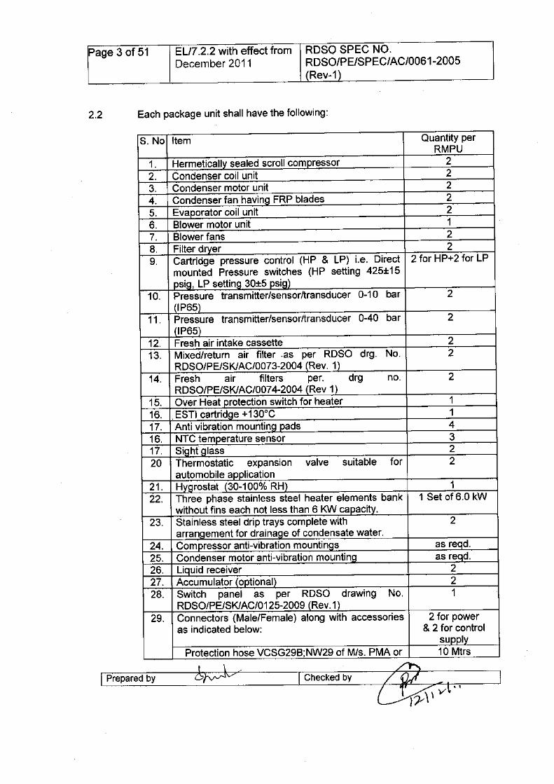
S.No Item Quantity perRMPU
1. Hermetically sealed scroll compressor 22. Condenser coil unit 23. Condenser motor unit 24. Condenser fan havinQ FRP blades 25. Evaporator coil unit 26. Blower motor unit 17. Blower fans 28. Filter dryer 29. Cartridge pressure control (HP & LP) Le. Direct 2 for HP+2 for LP
mounted Pressure switches (HP setting 425±15psig, LP setting 30±5 psig)
10. Pressure transmitter/sensor/transducer 0-10 bar 2(lP65)
11. Pressure transm itter/sensor/transducer 0-40 bar 2(IP65)
12. Fresh air intake cassette 213. Mixed/return air filter ·as per RDSO drg. No. 2
RDSO/PE/SKIAC/0073-2004 (Rev. 1)14. Fresh air filters per. drg no. 2
RDSO/PE/SKIAC/0074-2004 (Rev 1)15. Over Heat protection switch for heater 116. .ESTI cartridge +130°C 117. Anti vibration mountinQ pads 416. NTC temperature sensor 317. Sight glass 220 Thermostatic expansion valve suitable for 2
automobile application21. Hygrostat (30-100% RH) 122. Three phase stainless steel heater elements bank 1 Set of 6.0 kW
without fins each not less than 6 KW capacity.23. Stainless steel drip trays complete with 2
arrangement for drainage of condensate water.24. Compressor anti-vibration mountings as reqd.25. Condenser motor anti-vibration mountinQ as reqd.26. Liquid receiver 227. Accumulator (optional) 228. Switch panel as per RDSO drawing No. 1
RDSO/PE/SKIAC/0125-2009 (Rev. 1)29. Connectors (Male/Female) along with accessories 2 for power
as indicated below: & 2 for controlsupply
Protection hose VCSG29B;NW29 of M/s. PMA or 10 Mtrs
I Prepared by I Checked by
Page 4 of 51 E1J7.2.2 with effect from RDSO SPEC NO.December 2011 RDSO/PE/SPEC/AC/0061-2005
(Rev-1)
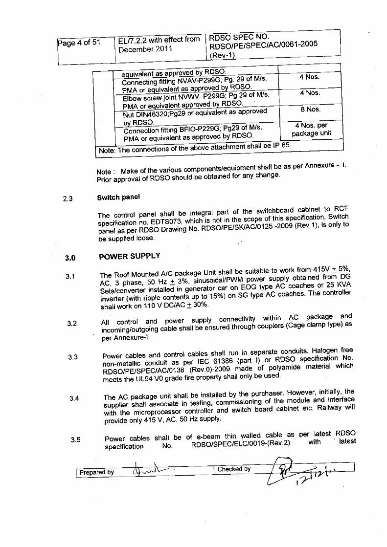
e uivalent as a roved b ROSO.Connecting fitting NVAV-P299G; Pg. 29 of M/s. 4 Nos.PMA or e uivalent as a roved b ROSO.Elbow screw joint NVWV- P299G; Pg 29 of M/s. 4 Nos.PMA or e uivalent a roved b ROSO.Nut OIN46320;Pg29 or equivalent as approved 8 Nos.b ROSO.Connection fitting BFIO-P229G; Pg29 of M/s. 4 Nos. perPMA or equivalent as approved by ROSO. package unit
Note: The connections of the above attachment shall be IP 65.
Note: Make of thevarious components/equipment shall be as per Annexure - I.Prior approval of ROSO should be obtained for any change.
The control panel shall be integral part of the switchboard cabinet to RCFspecification no. EOTS073, which is not in the scope of this specification. Switchpanel as per ROSO Drawing No. ROSO/PE/SKIAC/0125 -2009 (Rev 1), is only tobe supplied loose.
3.1 The Roof Mounted AlC package Unit shall be suitable to work from 415V ± 5%,AC, 3 phase, 50 Hz ± 3%, sinusoidallPWM power supply obtained from OGSets/converter installed in generator car on EOG type AC coaches or 25 KVAinverter (with ripple contents up to 15%) on SG type AC coaches. The controllershall work on 110 V OC/AC± 30%.
3.2 All control and power supply connectivity within AC package andincoming/outgoing cable shall be ensu'redthrough couplers (Cage clamp type) asper Annexure-I.
Power cables and control cables shall run in separate conduits Halogen freenon-metallic conduit as per IEC 61386 (part I) or RDSO s cification No.ROSO/PE/SPEC/AC/0138 (Rev.0)-2009 made of polyamide aterial whichmeets the UL94 VOgrade fire property shall only be used.
3.4 The AC package unit shall be installed by the purchaser. Howe er, initially, thesupplier shall associate in testing, commissioning of the modul and interfacewith the microprocessor controller and switch board cabinet e c. Railway willprovide only 415 V, AC, 50 Hz supply.
3.5 Power cables shall be of e-beam thin walled cable as pe latest ROSOspecification No. ROSO/SPEC/ELC/0019-(Rev.2) with latest
Page 5 of 51 ELI7.2.2 with effect from RDSO SPEC NO.December 2011 RDSO/PE/SPEC/AC/0061-2005
(Rev-1)
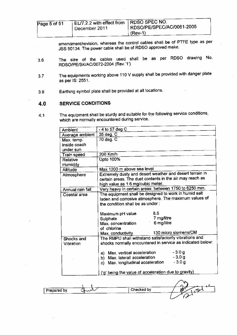
amendmenUrevision, whereas the control cables shall be of PTFE type as perJSS 50134. The power cable shall be of ROSO approved make.
3.6 The size of the cables used shall be as per ROSO drawing No.ROSO/PE/SKIAC/0072-2004 (Rev.'1')
3.7 The equipments working above 110 V supply shall be provided with danger plateas per IS: 2551.
4.1 The equipment shall be sturdy and suitable for the following service conditions,which are normally encountered during service. .
Ambient - 4 to 57 deg CAverage ambient 35 deg. CMax. temp. 70 deg. Cinside coachunder sunTrain speed 200 Km/hRelative Upto 100%HumidityAltitude Max 1200 m above sea levelAtmosphere Extremely dusty and desert weather and desert terrain in
certain areas. The dust contents in the air may reach ashigh value as 1.6 mg/cubic meter.
Annual rain fall Very heavy in certain areas: between 1750 to 6250 mm.Coastal area The equipment shall be designed to work in humid salt
laden and corrosive atmosphere. The maximum values ofthe condition shall be as under:
Maximum pH value 8.5Sulphate 7 mg/litreMax. concentration 6 mg/litreof chlorineMax. conductivity 130 micro siemens/CM
Shocks and The RMPU shall withstand satisfactorily vibrations andVibration shocks normally encountered in service as indicated below:
a) Max. vertical acceleration - 3.0 gb) Max. laterall acceleration - 3.0 gc) Max. longitudinal acceleration - 3.0 g
('g' being the value of acceleration due to gravity)
I Prepared by I Checked by ~··I
Page 6 of 51 ELn.2.2 with effect from RDSO SPEC NO.December 2011 RDSO/PE/SPEC/AC/0061-2005
(Rev-1)
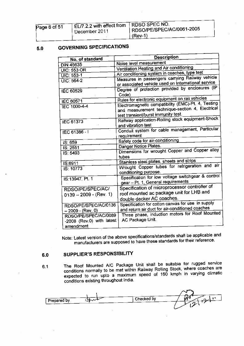
No. of standard DescriptionDIN 45635 Noise level measurementUIC:5530R Ventilation Heating and Air conditioningUIC: 553-1 Air conditioning system in coaches, type testUIC: 564-2 Measures in passengers carrying Railway vehicle
or associated vehicle used on International serviceIEC 60529 Degree of protection pro~ided by enclosures (IP
Code)IEC 60571 Rules for electronic equipment on rail vehiclesIEC 1000-4-4 Electromagnetic compatibility (EMC)-Pt. 4, Testing
and measurement technique-section 4, Electricaltest transient/burst immunity test.
IEC 61373 Railway application-Rolling stock equipment-ShoCkand vibration test
IEC 61386-1 Conduit system for cable management, Particularrequirement
IS: 659 Safety code for air-conditioningIS: 2551 Danger Notice Plates.IS: 5493 Dimensions for wrought Copper and Copper alloy
tubesIS:6911 Stainless steel plates, sheets and stripsIS: 10773 Wrought Copper tubes for refrigeration and air
conditioning purpose.IS:13947, Pt. 1 Specification for low voltage switchgear & control
gear - Pt. 1, General requirementsRDSO/PE/SPEC/ACI Specification of microprocessor controller of0139 - 2009 - (Rev. 1) roof mounted ac package unit for LHB and
double decker AC coaches.RDSO/PE/SPEC/AC/0136 Specification for cotton canvas for use in supply- 2009 - (Rev. 0) and return air duct for air-conditioned coachesRDSO/PE/SPEC/AC/0089 Three phase, induction motors for Roof Mounted-2008 (Rev.O) with latest AC Package Unit.amendment
Note: Latest version of the above specifications/standards shall be applicable andmanufacturers are supposed to have these standards for their reference.
6.1 The Roof Mounted AlC Package Unit shall be suitable for rugged serviceconditions normally to be met within Railway Rolling Stock, where coaches areexpected to run upto a maximum speed of 160 kmph in varying climaticconditions existing throughout India.
I Preparedby I Checkedby
Page 7 of 51 ELI7.2.2 with effect from RDSO SPEC NO.December 2011 RDSO/PE/SPEC/AC/0061-2005
(Rev-1)
6.2 The supplier shall be fully responsible for ensuring that all equipments formingpart of the supply is entirely fit for the purpose and no part of this specificationshall in any way remove or reduce his obligation in this respect. In addition, it isthe supplier's responsibility to underwrite the complete air-conditioning systemdesign and ensure that it is compatible with and will, in no way, compromise thedesign and performance of RMPU of his supply.
The supplier shall provide "In the field" service support during the guaranteeperiod.
6.3 The supplier shall supply any purpose built or special tools or equipment thatmay be necessary for the correct operation, servicing, testing or installation of theair - conditioning equipment.
6.4 The supplier will provide assistance, both in terms of material and technical, inthe development of the system as a whole to ensure that when this RMPU isinstalled as part of the integrated vehicle system, the performance of the systemmeets or exceeds the requirements specified.
6.5 If the RMPU fails to achieve these requirements, the RMPU shall be modified atthe supplier's expense and within a time scale to be agreed withpurchaser/consignee/RDSO.
7.1 The air conditioning package unit shall be able to work satisfactorily on self-generating, end on generation & Head on generation (HOG) type AC coaches.
a) Self-generating type coaches: Self-generating type coaches are providedwith inverters to convert the output of 130±5% V DC from the bogie mountedalternator to 415±5% VAC, 3 phase, 50 Hz supply. The unit shall be suitableto work on PWM supply with the ripple content of ±15%.
b) EOG type coaches: Power is supplied through electric power cars at eitherend of the rake. Supply available is 415±5% VAC, 3 Phase, 50 Hz.
c) HOG type coaches: Power is supplied through bulk converter provided inlocomotive or power car. Supply available is 415±5% VAC, 3 phase, 50 Hz.But it is PWM with ripple contents of 15%.
e) The compatibility of the units with the above supplies shall be ensured by themanufacturer. Manufacturer shall study power supply characteristics beforedesigning/selecting the sub-components of the system. Although, the sample
I Preparedby I Checkedby
Page 8 of 51 ELI7.2.2 with effect from ROSa SPEC NO.December 2011 ROSO/PE/SPEC/AC/0061-2005
(Rev-1)
wave form of the supply of AC coach is enclosed as annexure-O withmicroprocessor controller specification
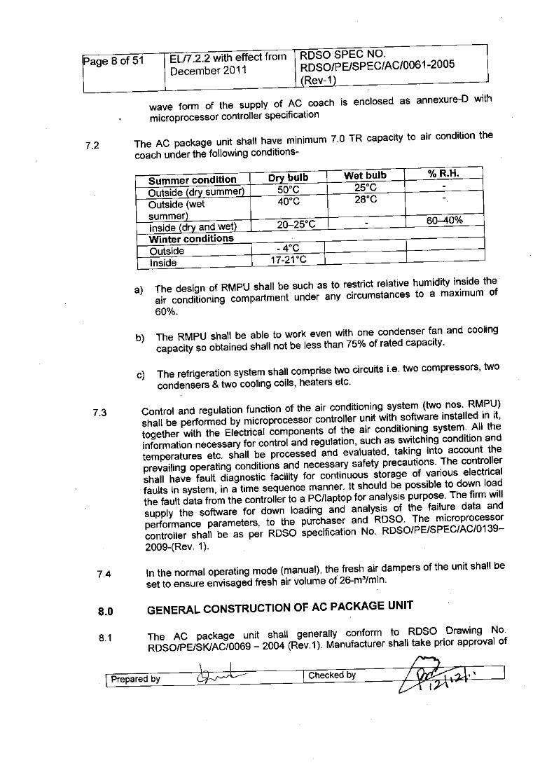
7.2 The AC package unit shall have minimum 7.0 TR capacity to air condition thecoach under the following conditions-
Wet bulb25°C28°C
a) The design of RMPU shall be such as to restrict relative humidity inside theair conditioning compartment under any circumstances to a maximum of60%.
b) The RMPU shall be able to work even with one condenser fan and coolingcapacity so obtained shall not be less than 75% of rated capacity.
c) The refrigeration system shall comprise two circuits i.e. two compressors, twocondensers & two cooling coils, heaters etc.
7.3 Control and regulation function of the air conditioning system (two nos. RMPU)shall be performed by microprocessor controller unit with software installed in it,together with the Electrical components of the air conditioning system. All theinformation necessary for control and regulation, such as switching condition andtemperatures etc. shall be processed and evaluated, taking into account theprevailing operating conditions and necessary safety precautions. The controllershall have fault diagnostic facility for continuous storage of various electricalfaults in system, in a time sequence manner. It should be possible to down loadthe fault data from the controller to a PC/laptop for analysis purpose. The firm willsupply the software for down loading and analysis of the failure data andperformance parameters, to the purchaser and ROSO. The microprocessorcontroller shall be as per ROSa specification No. ROSO/PE/SPEC/AC/0139-2009-(Rev. 1).
7.4 In the normal operating mode (manual), the fresh air dampers of the unit shall beset to ensure envisaged fresh air volume of 26-m3/min.
8.1 The AC package unit shall generally conform to ROSO Drawing No.ROSO/PE/SKIAC/0069 - 2004 (Rev. 1). Manufacturer shall take prior approval of
I Prepared by I Checked by
Page 9 of 51 ELfi.2.2 with effect from RDSO SPEC NO.December 2011 RDSO/PE/SPEC/AC/0061-2005
(Rev-1)
the structural drawing and the general layout of the components from ROSO.Bellows proposed to be used should also have approval of the ROSO. Bellowsshall be waterproof and have fire retardant properties. It shall conform to ROSOspecification No. ROSO/PE/SPEC/AC/0136 - 2009 - (REV. 0).
8.2 The Roof Mounted Package Unit shall be self-supporting and will not form part ofthe vehicle structure. For the module of unit, a separate structural frame shall beemployed which will not rely on any of the installed components or equipment forrigidity or strength. All the parts that require periodic cleaning or maintenanceshall be easily accessible when the unit is in installed condition. The parts thatrequire periodical cleaning shall be easily removable with minimum tools andattended to for which facility shall be made available.
8.3 The unit shall be made of stainless steel SS 304 grade S2 to IS: 6911. Weldedzones may be given necessary treatment after fabrication and shall not bepainted. Thickness of the sheet shall be minimum 1.6 mm. Thickness of thesheet may be increased in some areas for adequate strengthening againstvibration and shocks. The thickness of the channel/angle employed for structureshall not be less than 2.0 mm. Similarly, the thickness of the channel/angleprovided for mounting motors, compressors & coils shall not be less than 2.5mm.
8.4 Roof mounted AC package unit shall be capable of handling by overhead liftinggear without sustaining damage. The lifting points for this purpose shall beprovided as given in ROSO drg. No ROSO/PE/SPEC/AC/0069 - 2004 (Rev.1).The supplier shall give the details of special handling requirement, if any.
8.5 The actual weight of the AC package unit after it weighment would be marked inthe space as indicated in ROSO drawing no. ROSO/PE/SPEC/AC/0069 - 2004(Rev. 1). The actual weight of the AC Package unit shall not exceed 700 Kg.
8.6 The Roof mounted AC package unit will be so designed that it interfaces with thevehicle and does not allow rainwater, washing plant fluid and condensate to enterinto the vehicle. The connection of the supply air opens to the main duct and thereturn air opening shall be through bellows with metallic frame at both the ends.The bellows shall be detachable from the unit as well as from the duct side. Theconnection of the ductlcoach/and to the package unit would be through nuts andbolts. Bellows should be of superior quality of woven material as per ROSOspecification No. ROSO/PE/SPEC/AC/0136-(Rev.0)-2009. It shall be of ROSOrecommended make only. Bellows as well as their connections with the packageunit should be water proof & fire retardant. The metallic frame shall have slide inarrangement, so that the bellow may be replaced without having to remove theunit from the coach.
The design and layout of RMPU shall be such as to prevent water traps even ifthe vehicle is stopped on the slope or cant. Proper water drainage arrangementshall also be provided. Each drip tray shall have drain holes/hole fitted withdrainpipe to facilitate easy drainage of water without allowing out side air to be
kJV I Checked byI Prepared by
Page 10 of 51 EU7.2.2 with effect from RDSO SPEC NO.December 2011 RDSO/PE/SPEC/AC/0061-2005
(Rev-1)
sucked inside the evaporator compartment. Drain pipe to drain out condensatewater from drip trays, should be integral part of the drip tray and, if required willhave suitable trap at free end, to prevent the condensate water being sucked inby blower and thrown in the supply air duct. Any change in the approveddesign/equipment requires prior approval of RDSO.
8.8 Drip trays, provided under cooling coils to collect condensate water should be ofstainless steel SS 304 grade S2 to IS: 6911 and should have a depth not lessthan 60 mm. It's design should be such. as to prevent spillage of water inevaporator compartment. The condensate water shall not be stored/collected inblower/runner area of evaporator compartment.
8.9 If required, both the refrigeration circuit of RMPU will have accumulator (optional)of adequate capacity to prevent liquid refrigerant from entering the,compressors.
8.10 No external connections/fittings shall be provided by the purchaser whileinstalling the RMPU. No material shall be used that will support infestation of anykind.
a) No material shall be used in the construction of the unit that is liable to beadversely affected by the vibrations, damp, rotting or growth of modules. Notimber shall be used. Use of asbestos is prohibited.
b) Fire protection: the design of all the parts and component of the unit shallmeet the requirements of UIC 564-2 in the fire classification-1.
8.12 The evaporator compartment of the AC package unit shall be watertight andthere should be no leakage of water into the evaporator compartment fromoutside as well as from bottom of the RMPU when tested for water tightness.
Sealant over threads shall only be allowed. The sealant used shall have fireretardant properties.
8.13 The noise level generated by the running of the package unit in the installedcondition shall be as low as possible, and not raise the resultant noise levelinside the coach to more than 60 dB as per UIC 553, neither at standstill norduring operation. The condenser fans and the compressors shall have anti-vibration mounting to avoid structure borne noise transmission into the coach.The noise level shall be measured during commissioning of the unit.
8.14 A protective wire mesh guard/punched sheet metal guard shall be provided overthe package unit covering the entire condenser portion. Protective guard shall bemade from stainless steel wire of 00 not less than 3 mm or punched steel sheetof thickness 2 mm. The guard shall be as shown in RDSO drawing no.RDSO/PE/SPEC/AC/0069 - 2004 (Rev.1). The gap between the wire mesh and
I Prepared by P? I Checked by ~""'" ::'I\I~
\r)/
Page 11 of 51 EU7.2.2 with effect from ROSO SPEC NO.December 2011 RDSO/PE/SPEC/AC/0061-2005
(Rev-1)
the condenser fan blades shall not be less than 25 mm. Under anycircumstances, the condensing coils cover should not touch with coils to protect itfrom damage during maintenance.
8.15 The compartment containing the cooling coils/heaters, blower fans shall bethermally insulated from all sides, top and bottom. The insulating·material usedshall be of fire retardant quality preferably resin bonded fiberglass or fireretardant polyethylene or combination of both or closed cell non-water absorbingfire retardant elestomeric melamine or any other suitable material. Manufacturershould obtain prior approval from ROSa for any other type of Insulating materialproposed to be used. The technical details such as thermal conductivity, density,fire retardancy, water absorption and tensile strength etc of insulating materialare to be furnished by the firm to ROSa. The thermal insulation shall besandwiched and jacketed between two layers. The thermal insulation shall not beexposed outside from inside.
8.16 The evaporator blower shall be designed for air delivery at 20mm static head ofwater gauge.
8.17 The equipments/components in the evaporator compartment which require inservice attention shall be easily accessible from top of the coach with the help ofladder under high-tension line. The top cover of the evaporator compartmentshall be leak proof. A lever should be there to push open the top cover upward asshown in the ROSa Org. No ROSa/PE/SPEC/AC/0069- 2004 (Rev.1).Necessary arrangement to hold the covers in open condition shall be providedduring maintenance. The latches shall have sufficient strength and positivelocking, so that the service cover does not open during service.
8.18 The package unit shall be installed above the false ceiling under the coach roofwith condenser portion exposed.
RMPU should work on vapour compression refrigeration system withrefrigerant.
i) Major equipments/components shall be replaceable on a unit exchangebasis.
ii) The design philosophy shall be.of no leaks and a sealed system (with sealedscroll compressors).
iii) The electrical and control connections shall be provided with lockingarrangement and shall be easily accessible for maintenance.
I Preparedby I Checked by
Page 12 of 51 EL/7.2.2 with effect from ROSO SPEC NO.December 2011 RDSO/PE/SPEC/AC/0061-2005
(Rev-1)
8.21 The electrical power & control connection to the motors, compressors andheaters etc shall be through four numbers heavy duty connectors (two on eachside). The connectors shall be ROSO approved make as per annexure-I.
8.22 Two numbers of electrical junction boxes having aluminum die-cast face (front),on which the connector's base to be mounted, shall be provided on both sides.The design of aluminum die-cast face shall slightly be tapered towards bottom. Itshall be ensured that under any circumstances the water should not enter intothe electrical box. The rear portion of the box shall be stainless steel as per SS304 grade S2 to IS: 6911. Din rail mounted terminal blocks shall be provided.The make of the terminal block shall be as per annexure - I. Power and controlconnection diagram of terminal blocks on aluminum plate with anodizing of blackback ground or with silk screen printing in permanent nature shall be providedeither from inside of the cover or on the top of cover of junction box. The diagramshall contain terminal number & wire number (ferrules) for easy identification formaintenance staff of Indian Railways.
8.23 The electrical junction box shall be fitted from inside of the opening provided forthe same. It shall be ensured that there should be no water entrance from theopening made for the purpose.
8.24 The RMPU shall be marked with the following information in the front & back, asshown in the drawing:
1. Type/Make2. Serial Number3. Month and year of manufacture4. Weight5. Capacity in TR/KcaIlH (under specified condition)6. Power consumption (under specified condition)7. Refrigerant. '" Quantity '" '" Kg.
Compressors, all motors, heaters and frame of the unit shall be provided withsuitable flexible braided copper (tin coated) jumpers with crimped socket oneither ends for double earthing. The earthing scheme of the unit shall generallybe as per HFG drawing No. S65F-100.931-13A.Z4.
All the electrical equipments and wiring etc. on the RMPU shall meet theprovisions of Indian electricity act and rules.
Only hermetically sealed scroll Compressors suitable for rolling stock applicationshall be used.
I~p-r-ep-a-re-d-b-Y---~-/---I Checkedby
Page 13 of 51 EL/7.2.2with effect from RDSO SPEC NO.December 2011 RDSO/PE/SPEC/AC/0061-2005
(Rev-1)
8.28.2 The refrigerant compressors shall have minimum 3.5 TR capacity at 60°Ccondensing and 5°C evaporating temperature. The manufacturer shall furnish thedesign parameters of superheat and sUb-coolingof refrigerant.
8.28.3 A clamp to hold the compressor from the top shall be provided. The top cover ofcondensing compartment shall not touch the compressor dome to avoid damageto compressor during service.
8.28.4 The rating of the AC package unit shall not be less than 7.0 TR at the conditionsspecified in the clause 7.2 of the dry summer conditions, keeping the maximumpower consumption of the unit below 16.5 KVA.
8.29.1 The heat exchangers (condensers) shall be air cooled and of adequate capacityto match the refrigeration system.
8.29.2 The evaporator unit shall comprise cooling and heating units with expansion. valve.
8.29.4 To increase the operating life, the heat exchangers shall be pre-coated and shallpass 1000 Hours salt fog test as per ASTM B-117. In this regard, a test certificatefrom OEM/NABL accredited lab shall be furnished by the manufacturer.
8.29.5 The fins should be uniformly distributed throughout the entire length of the tubes.Spacers may be used to maintain uniform distance between the fins duringmanufacture before expansion of the tubes.
8.29.6 There should be adequate grip of the fins over the tubes and the fins should haveflared collars so that during vibration, the fins do not come closer and collar of thefins does not go inside the holes of the adjacent fins thereby reducing thespacing. The coils shall be mechanically expanded.
8.29.7 The mounting details of the heat exchangers shall be furnished by themanufacturer at the time of prototype inspection.
8.29.9 The condenser compartment should be sUitably sealed to achieve the optimumcondenser efficiency. The inlet air through condenser coil shall be ensured.
I Preparedby I Checked by
Page 14 of 51 ELI7.2.2 with effect from RDSO SPEC NO.December 2011 RDSO/PE/SPECI AC/0061-2005
(Rev-1)
8.29.10 Heat exchangers shall be provided with guard from top, bottom and sides toavoid damage during service.
8.29,11 Any new design of coil which gives better performance than existing type of coilcan also be offered. Manufacturer shall submit complete details of such coil toROSO before prototype test. RMPU with such design of coil shall be put on fieldtrial before prototype clearance is granted.
8.30.1 The unit shall be able to supply fresh air at the rate of 0.35 m3/minute/person inall type of AC coaches.
8.30.2 Each air conditioning unit shall suck in outside ambient air from the lateral coachwall via the special grills provided in the coach.
8.30.3 Two 'adjustable air dampers (louvers) shall be installed in the unit. These louversshall be adjusted manually and the design shall be made in such a way that theymay be fixed at any position by means of locking arrangement and adjustment bylever as per the fresh air requirement. The louvers shall be adjusted atcommissioning stage itself.
8.31.1 Each air conditioning unit shall have 2 fresh air and 2 return/mixed air filters. Thefresh air filters shall be installed outside the air conditioning unit directly behindthe fresh air intake grills in the upper part of the lateral wall of the coach. Themixed air filters shall have large intake area and shall be situated inside the unit.Mixed air filter shall cover entire face of the cooling (evaporator) coil to get theoptimum utilization of their designed capacity. A separate housing toaccommodate the mixed air filter shall be provided.
8.31.2 The fresh air filters and the mixed/return air filters shall be as per drawing No.ROSO/PE/SKIAC/0074-2004 (Rev.1) and ROSO/PE/SKIAC/0073-2004 (Rev.1)respectively. Only ROSO approved make filters shall be used.
8.31.3 The fresh air filters shall be serviced from the lateral side wall of the coach afteropening the fresh air intake grille (cassette). The filter shall be easily pulled outfrom bellow/cassette. The cover of the cassette shall be designed in such a waythat during service, it could not be unbolted/unscrewed/unlatched. The mixed airfilters shall be serviced from the top after opening the two maintenance/servicecovers of the evaporator compartment. Access shall be possible by using aladder without the necessity to climb on to the roof.
8.31.4 The proper procedure for cleaning of filters along with the cleaning agent, ifrequired, shall be furnished from the OEM.
I Preparedby I Checked by
Page 15 of 51 ELI7.2.2 with effect from ROSO SPEC NO.December 2011 RDSO/PE/SPEC/AC/0061-2005
(Rev-1)
The seat for return/mixed air filter will have necessary provIsion (pins) toaccommodate and to match the filter having arrangement to avoid wrong fitmentas per drawing no. RDSO/PE/SKIAC/0073 - 2004 (Rev.1).
A test certificate from OEM indicating serial number of filter, efficiency, dustholding capacity and initial/maximum pressure drop shall be furnished by RMPUmanufacturer. .
Arrangement should be available to lock the fresh and mixed/return air dampersat any position. Adjustment of dampers with locking arrangement should not getdisturbed on its own during run.
The humidity control or dehumidification process shall be started when required.The steps for this process shall be as per clause (8) of annexure - IV (enclosedwith the specification)
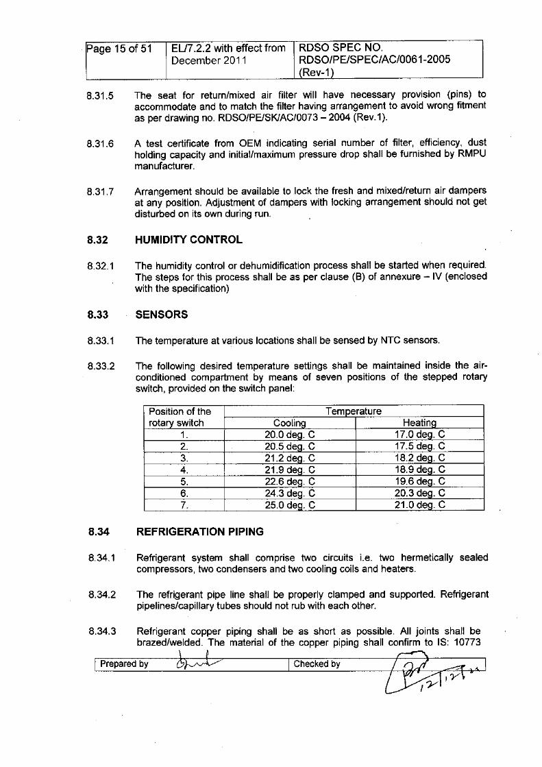
The following desired temperature settings shall be maintained inside the air-conditioned compartment by means of seven positions of the stepped rotaryswitch, provided on the switch panel:
Position of therotary switch
1.2.3.4.5.6.7.
Heatin17.0 de . C17.5 de . C18.2 de . C18.9de . C19.6 de . C20.3 de . C21.0 de . C
Coolin20.0 de . C20.5 de . C21.2 de . C21.9 de . C22.6 de . C24.3 de . C25.0 de . C
Refrigerant system shall comprise two circuits Le. two hermetically sealedcompressors, two condensers and two cooling coils and heaters.
The refrigerant pipe line shall be properly clamped and supported. Refrigerantpipelines/capillary tubes should not rub with each other.
Refrigerant copper piping shall be as short as possible. All joints shall bebrazed/welded. The material of the copper piping shall confirm to IS: 10773
~ I Checked by te?il-;-:;:q ,- I(y,y
I Prepared by
Page 16 of 51 EU7.2.2 with effect from RDSO SPEC NO.December 2011 RDSO/PE/SPEC/AC/0061-2005
(Rev-1)
(latest edition) meeting the dimensional requirements as per IS: 5493, subjectto the minimum thickness of 1 mm. Inner grooved copper pipe shall only beused. Firm will submit a test certificate from any Govt. laboratory/Govt.recognized laboratory for confirmation of copper piping as per IS-10773 anddimensional requirement as per IS: 5493.
8.34.4 Each refrigeration system shall be separately protected by suitable safety devices,against over and under pressure. The control pressure switch shall have anautomatic reset. If the control pressure switch operates the safety devices, thisshall be recorded by the microprocessor controller unit and indicated. It shall beensured that if the working pressure increases beyond 275 psig, the secondcondenser fan will be in working otherwise only one condenser fan will be inworking condition.
8.34.5 Filter drier unit with sight glass shall be connected into the liquid refrigerationpipeline and shall be of RDSa approved make only as specified in annexure - I.The filter drier must be installed with flow in the direction of the arrow on the filterdrier label.
8.34.7 Thermal/electronic expansion valve suitable .for automobile application shall beused. The feeler/sensor of expansion valve shall be properly support~d andclamped to avoid any damage due to vibration and rubbing. The feeler bulb of theexpansion valve shall properly be thermally insulated, so that it can only sense thetemperature of refrigerant coming out from the evaporator coil.
8.34.8 Expansion valves with external pressure equalization must be used. Theequalizing line must be connected to the suction line immediately after the bulb. .
8.34.9 The bulb shall not be located at the bottom of the suction line due to the possibilityof oil lying in the bottom of the pipe causing false signals. The bulb should bemounted in the suction line just after evaporator coil and in a positioncorresponding to between 1 O'clock and 4 O'clock'. Similarly, equalizing lineshould be connected in the suction line immediately after the bulb.
8.34.10 The stainless steel liquid receiver of adequate capacity shall be provided in theliquid line.
8.34.11 The refrigerant circuit shall be provided with suitable pressure transducers asshown in drawing No. RDSP/PE/SKIAC/0071 - 2004 (Rev.1), so that the workingpressure of refrigerants of different cooling circuits can be monitored by means ofrotary switch, provided on switch panel.
8.34.13 Refrigerant circuit shall be protected against high and low pressure by prOVidingHP/LP cutout sWitches. These switches shall be mounted directly on the
I Prepared by I Checked by
Page 17 of 51 ELn .2.2 with effect from RDSO SPEC NO.December 2011 RDSO/PE/SPEC/AC/0061-2005
(Rev-1)
refrigerant pipe line as shown in ROSO drawing No. ROSO/PE/SKIAC/0071(Rev.1).
8.34.14 In case the HP/LP cut outs are mounted, where the rain water comes directly onit, a cover from the top shall be provided.
8.35.1 Motors provided in the package unit shall be continuously rated and shall conformto ROSO specification No. ROSO/PE/SPEC/AC/0089 - 2008 (Rev.O) withamendment NO.1 & 2 having IP-56 protection to IEC 60529. Insulation class of allthe motors shall be 'H'. The motors shall only be of ROSO approved make.
Condenser fan motorBlower motor
0.75 KW, 415V, 50 Hz., 1400 RPM (two nos.)1.1 KW, 415V, 50 Hz., 1400 RPM (one no.)
Evaporator blower fan motors shall be capable of operating continuously underhigh ambient temperatures and un"der the effect of any radiant heat from theheater bank, which may be experienced during normal operation.
The direction of the rotation of motors shall be arrow marked clearly on the coverover condensing area. Similarly, the rotation of blower motor shall be marked onthe fan duct from outside. The marking shall be of permanent nature.
Manufacturer shall submit mounting details of condenser and blower motoralongwith the drawing of blower fan and condenser fan.
The condenser fans shall be made of Fire Retardant Plastic material blades withaluminum hub. The minimum required properties (mechanical, physical andthermal) for Fire retardant Plastic material used for condenser blade should be asfollowing:
I Prepared by
Melting point(ASTM method 02177)- 218 deg.CTensile stress (ASTM method 0638)- 90 MPaFlexural stress (ASTM method 0790)- 130 MPaElongation @ Break (ASTM method 0638)- 4 - 6%Impect strength (ASTM method 0256A)- 6.0 Kg. cm.lcm.Rockwell hardness (ASTM method 0785)- 120 R. ScaleHeat defelection temp. @ 18.5 Kg/cm210ad- 180 deg.C(ASTM method 0648)Flammability rating - VO UL94Glass fibre/ash content - (ISO 3451-1) 30 - 35%
t;V I Checked by
Page 18 of 51 EU7.2.2 with effect from RDSO SPEC NO.December 2011 RDSO/PE/SPEC/AC/0061-2005
(Rev-1)
Air shall be drawn (not blown) over the cooling coil (Le. suck througharrangement). Arrangement shall be made to prevent sucking of condensatewater by evaporator blower motor.
The condenser fan blade and runner of the evaporator blower shall bedynamically balanced. Manufacturers will keep serial no., batch no.,manufacturing date and balancing record and shall be produced before inspectingofficial, if demanded.
The evaporator unit shall contain 6.0 kW heaters for heating of the coach duringwinter. These heaters shall be of highest reliability standard to obviate any firehazard. Type/make of the heater shall be furnished by the firm.
The electrical heaters shall have following triple protection against their excessivetemperature rise through protective devices:
1) Over heat protection2) Intermediate protection and3) Fusible link
Protection at S.No. 1 & 2 shall be actuated through microprocessor controller at65 deg.C &85 deg.C respectively, whereas the protection at S.No.3 is ultimatedisconnection of power supply to heating elements at 130 deg.C. The logic isdescribed at annexure-IV
8.37.1 The cable sizes shall be as specified in RDSO drawing No.RDSO/PE/SKIAC/0072 -2004 (Rev.1)
Power and control cables shall run in separate pliable conduits of insulatingmaterial, in case the sheathed cable is not used.
The conduit shall be halogen free confirming to IEC 61386 - I or as per RDSOspecification No. RDSO/PE/SPEC/AC/0138 (Rev.O)-2010.A certificate in supportof conformity from OEM shall be produced by the firm. The connections of theaccessories of the fittings with conduit shall have IP 67 protected, so that in anycircumstance foreign material/water could not get entered into the conduit.
Cable should be so laid in RMPU that the removal of any defective cable is easilypossible.
Earthing scheme shall generally be as per HFG drawing No. S65F-100.931-13A.Z4, enclosed with the specification.
I~p-r-ep-a-re-d-b-Y--~ I Checkedby
Page 19 of 51 ELfi .2.2 with effect from RDSO SPEC NO.December 2011 RDSO/PE/SPEC/AC/0061-2005
(Rev-1)
Cable shall be crimped at both ends with suitable copper lugs. Copper lugs havingfire retardant shrinkable sleeve .over it shall only be used.
Fire retardant computer generated cable markers shall be provided foridentification of cables.
Compressors, all motors, heaters & AC package unit frame shall be provided withsuitable flexible braided copper jumpers with crimped socket at either side of thejumpers for double earthing as indicated in HFG drawing No. S65F-100.931-13A.Z4.
The microprocessor controller shall be of ROSO approved make as per ROSOspecification No. ROSO/PE/SPEC/AC/0139-(Rev.O)-2009. The logic for controland regulation of the air-conditioning system is also enclosed with thespecification of microprocessor controller.
Only after the drawings and the design have been approved and the clearancegiven to this effect, the manufacturer shall take up the manufacture of theprototype. It is to be clearly understood that any changes. required to be done inthe prototype or any additional tests other than specified herein are required tobe conducted on the prototype unit or its components, they shall be doneexpeditiously.
The type tests shall be carried out by ROSO representative on prototype uniteither totally or in part under the following conditions without any additional cost:
• A manufacturer undertakes to manufacture for the first time as per thisspecification.
• An important change in design details of machine has been introduced.• Specification is modified necessitating the re-designing of equipment.• Unsatisfactory performance reported from user Railways.• Resumption of production after an interruption of more than two years.
9.3 ROSO may conduct surprise checks on the manufacturing process and qualitycontrol along with any of the tests to ensure quality of product and itsconformance to ROSO specification.
I-~-r-ep-a-re-d-b-Y--~~----I Checkedby
Page 20 of 51 EU7.2.2 with effect from RDSO SPEC NO.December 2011 RDSO/PE/SPEC/AC/0061-2005
(Rev-1)
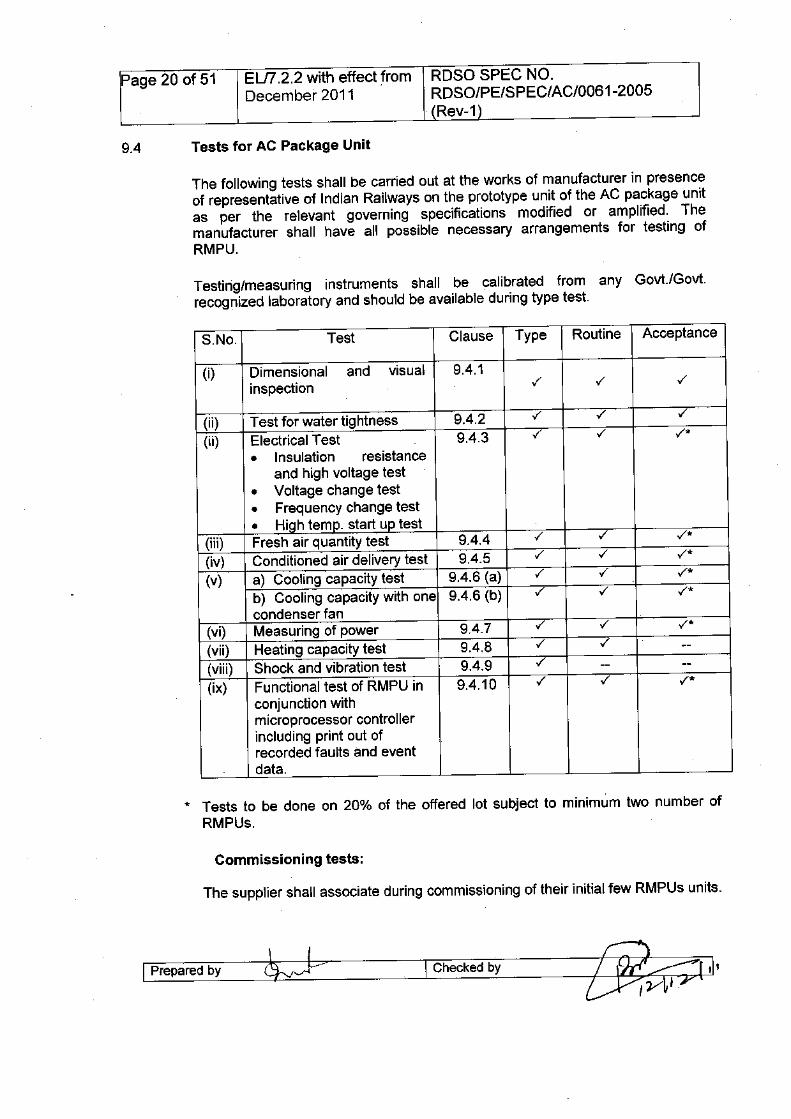
The following tests shall be carried out at the works of manufacturer in presenceof representative of Indian Railways on the prototype unit of the AC package unitas per the relevant governing specifications modified or amplified. Themanufacturer shall have all possible necessary arrangements for testing ofRMPU.
Testing/measuring instruments shall be calibrated from any Govt.lGovt.recognized laboratory and should be available during type test.
S.No. Test Clause Type Routine Acceptance
(i) Dimensional and visual 9.4.1inspection ./ ./ ./
(ii) Test for water tightness 9.4.2 ./ ./ ./
(ii) Electrical Test 9.4.3 ./ ./ ./*
• Insulation resistanceand high voltage test
• Voltage change test• Frequency change test• High temp. start up test
(iii) Fresh air quantity test 9.4.4 ./ ./ ./*(iv) Conditioned air delivery test 9.4.5 ./ ./ ./*(v) a) Cooling capacity test 9.4.6 (a) ./ ./ ./*
b) Cooling capacity with one 9.4.6 (b) ./ ./ ./*condenser fan
(vi) Measuring of power 9.4.7 ./ ./ ./*(vii) Heating capacity test 9.4.8 ./ ./ --(viii) Shock and vibration test 9.4.9 ./ -- --(ix) Functional test of RMPU in 9.4.10 ./ ./ ./*
conjunction withmicroprocessor controllerincluding print out ofrecorded faults and eventdata.
* Tests to be done on 20% of the offered lot subject to minimum two number ofRMPUs.
I Prepared by I Checked by
Page 21 of 51 EU7.2.2 with effect from RDSO SPEC NO.December 2011 RDSO/PE/SPEC/AC/OO61-2005
(Rev-1)
This includes checking the overall dimensions, correct electrical wiring, locationof the lifting hooks, material of the filters, accessibility of the blower motor, filtersand protective devices in the switch panel, quality of the welding and over allworkmanship of RMPU.
The unit shall be tested by the manufacturer for the water tightness as per thetest arrangement and test programme described below: -
The water tightness of the body al1d the electrical equipment boxes mountedoutside the body shall be checked at all the openings, doors, covers, cover stripsor crevices, which might allow penetration of the water or snow.
A distinction shall be made between the water tightness of the openings (Air inletetc.), which depends primarily on the erection and condition of the joints.
i) A check on the water tightness of the openings shall form type test. It shall becarried out for a period of 30 minutes with all the fans running under the artificialrain of intensity not less than 60 mm per minute. The angle of the rain will be 45degrees towards the evaporator compartment from the condenser side.
ii) A check on the water tightness of the covers shall be conducted. It shall becarried out by means of a jet of 6 to 10 mm internal diameter, at a distance of 2meters and a pressure of 1 bar with all fans running and then a pressure of 3bars with the fans stopped. The water shall be sprayed on each cover/sideminimum for 15 minutes.
Hi) In each case, the penetration of water shall not be of such nature as to havean adverse effect on cabling and electrical equipment or any other equipmentnecessary for maintaining the vehicle in proper working order.
This test will be conducted to see the efficacy of condensate water drain outsystem from the AC package unit. The firm will make a mock up incorporating theactual installation of AC package unit with blower motor in working condition.
l-p-re-p-ar-ed-bY---~-vvb·
Insulation resistance of compressor & other motors shall not be less than 100mega· ohms with 1000V dc megger, in all weather conditions.
zj?~,~A2JI Checkedby
Page 22 of 51 ELI7.2.2 with effect from ROSO SPEC NO.December 2011 ROSO/PE/SPEC/AC/0061-2005
(Rev-1)
Work test certificate from original equipment manufacturer (OEM) certifying theequipment to withstand a voltage of 2000V AC for one minute shall be furnished.
During the normal operation of the unit under cooling capacity test (clause 9.5.6)condition, the power source voltage will be changed from 375V AC to 460V AC.
The RMPU shall operate without any significant change of suction and dischargepressure.
During the normal operation of the unit under cooling capacity test (clause 9.5.6)condition, the power source frequency shall be changed to 47.5 to 52.5 Hz.
The RMPU shall operate without significant change of discharge and suctionpressure.
The condenser room temperature shall be maintained at 57°C and the ACpackage unit shall be made to run for one hour.
The RMPU should work satisfactorily without tripping of any of the protectivedevices.
Measurement of fresh air quantity shall be made when the fresh air openings arein normal position and fresh air will be measured at 415 volts - 5% Le. 394 volts.The fresh air quantity should not be less than 26 CMM.
This test shall be conducted by adjusting the static head of 20mm WG over theconditioned room air.
Air velocity measurements shall be recorded at both the return air openings. Bothfresh air filters shall be closed & the conditioned air delivery should be within thevalue declared by the manufacturer in Annexure - II.
I-P-re-p-a-re-d-b-y---~-'---I Checked by
Page 23 of 51 ELn.2.2 with effect from RDSO SPEC NO.December 2011 RDSO/PE/SPEC/AC/0061-2005
(Rev-1)
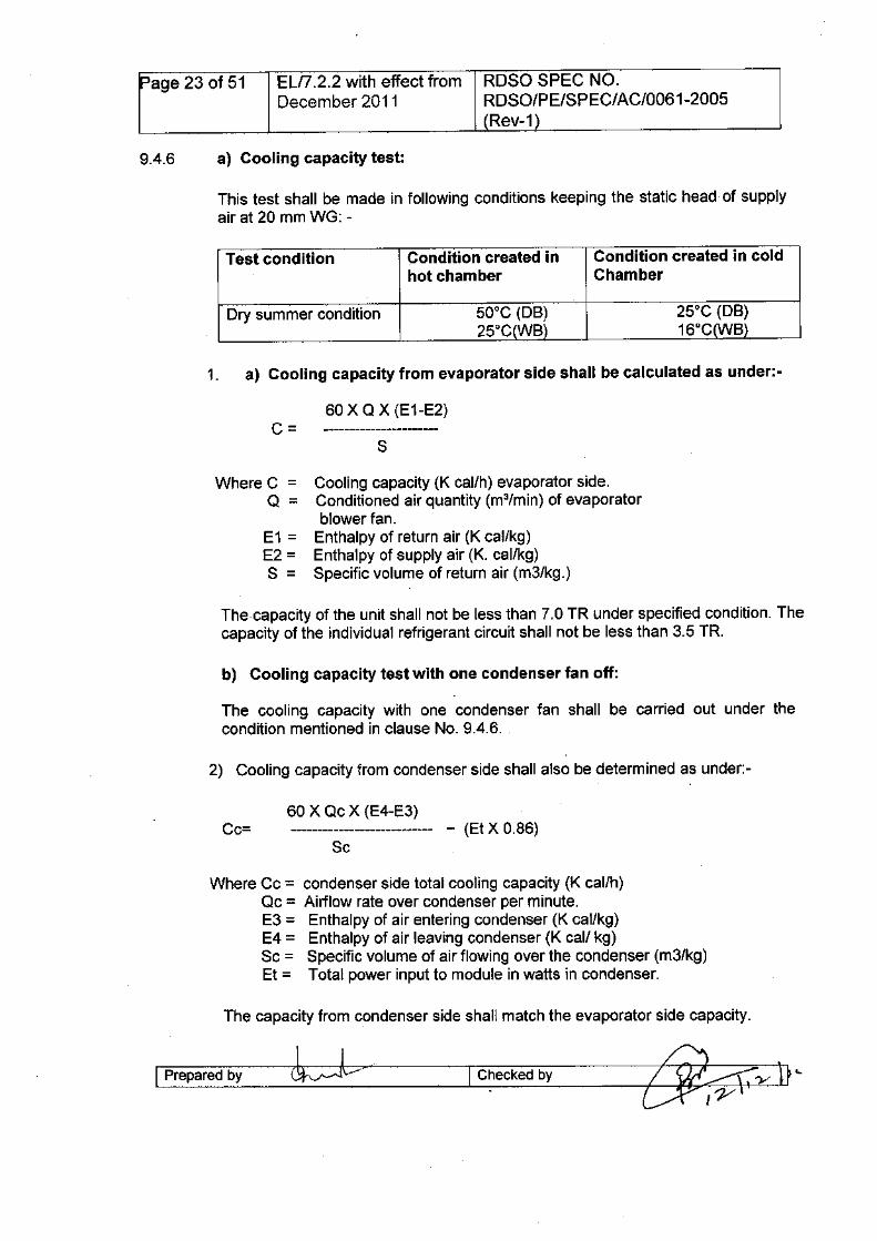
This test shall be made in following conditions keeping the static head of supplyair at 20 mm WG: -
Test condition Condition created inhot chamber
Condition created in coldChamber
Dry summer condition 50°C (DB)25°C WB
Where C = Cooling capacity (K cal/h) evaporator side.Q = Conditioned air quantity (m3/min) of evaporator
blower fan.E1 = Enthalpy of return air (K cal/kg)E2 = Enthalpy of supply air (K. cal/kg)S = Specific volume of return air (m3/kg.)
The capacity of the unit shall not be less than 7.0 TR under specified condition. Thecapacity of the individual refrigerant circuit shall not be less than 3.5 TR.
The cooling capacity with one condenser fan shall be carried out under thecondition mentioned in clause No. 9.4.6.
Where Cc = condenser side total cooling capacity (K cal/h)Qc = Airflow rate over condenser per minute.E3 = Enthalpy of air entering condenser (K cal/kg)E4 = Enthalpy of air leaving condenser (K cal/ kg)Sc = Specific volume of air flowing over the condenser (m3/kg)Et = Total power input to module in watts in condenser.
I~p-r-ep-a-re-d-b-Y---cbdv I Checkedby
Page 24 of 51 ELI7.2.2 with effect from RDSO SPEC NO.December 2011 RDSO/PE/SPECIAC/0061-2005
(Rev-1)
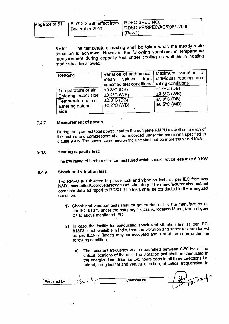
Note: The temperature reading shall be taken when the steady statecondition is achieved. However, ,the following variations in temperaturemeasurement during capacity test under cooling as well as in heatingmode shall be allowed:
Variation of arithmeticalmean values froms ecified test conditions±0.3°C (DB)±O.2°C WB±0.3°C (DB)±0.2°C (WB)
Maximum variation ofindividual reading fromratin conditions±1.0oC(DB)±O.5°C B±1.0oC(DB)±0.5°C (WB)
Temperature of airEnterin indoor sideTemperature of airEntering outdoorside
During the type test total power input to the complete RMPU as well as to each ofthe motors and compressors shall be recorded under the conditions specified inclause 9.4.6. The power consumed by the unit shall not be more than 16.5 KVA.
The RMPU is sUbjected to pass shock and vibration tests as per IEC from anyNABL accredited/approved/recognized laboratory. The manufacturer shall submitcomplete detailed report to ROSa. The tests shall be conducted in the energizedcondition.
1) Shock and vibration tests shall be got carried out by the manufacturer asper IEC 61373 under the category 1 class A, location M as given in figureC1 to above mentioned IEC.
2) In case the facility for conducting shock and vibration test as per IEC-61373 is not available in India, than the vibration and shock test conductedas per IEC-77 (latest) may be accepted and it shall be done under thefollowing condition:
a) The resonant frequency will be searched between 0-50 Hz at thecritical locations of the unit. The vibration test shall be conducted inthe energized condition for two hours each in all three directions i.e.lateral, Longitudinal and vertical direction, at critical frequencies. In
I Prepared by ~-~---<J;)~l ,n_'~~ I Checked by ~
Page 25 of 51 ELI7.2.2 with effect from RDSO SPEC NO.December 2011 RDSO/PE/SPEC/AC/0061-2005
(Rev-1 )
case critical frequency is not observed, vibration test shall beconducted at 10Hz. '
b) Shunting shocks test shall be conducted by giving 12 shocks of 3 glevel each in the energized condition of unit in all the three direction.
(NOTE: Tests specified in clause 9.4.9 shall be carried out in energizedcondition)
Functional test of RMPU in conjunction with microprocessor controllerincluding print out of recorded faults and event data
The following tests shall be carried out on RMPU in conjunction withmicroprocessor, as specified in RDSO specification No.RDSO/PE/SPEC/AC/0139 (Rev.1)-2009:
1) Starting of compressors: Both the compressors shall not be started at a. time. First compressor of each unit should be started after 2 minutes from
switching ON of AIR-CO switch. Second compressors of the units shall bestarted after a delay of 5 seconds from start of first compressors, ifrequired.
2) High Pressure switches: The compressor should be switchedOFF/tripped, if discharge pressure of compressor rises beyond limit of 430psig. Once the compressor has been switched OFF, it shall not be startedbefore 5 seconds even if it is required.
If the compressor tripped three times in one hour, the fault shall bestored/displayed by means of the glowing fault indication lamp provided onswitch panel, in addition to LED indication.
In case both the compressors of any unit are switched OFF at a time, firstcompressor shall be started after 1 minute and other one after 5 secondsfrom start of the first compressor.
The provision shall be there to restart the unit in case both the compressorshave been tripped three times in onehour.
3) Low Pressure switches: The compressor should be switchedOFF/tripped, if suction pressure of compressor goes down beyond the limitof 30 psig. Once the compressor has been switched OFF, it shall not bestarted before 5 seconds even if it is required.
If the compressor tripped three times in one hour, the fault shall bestored/displayed by means of the glowing fault indication lamp provided onswitch panel, in addition to LED indication.
I'--p-re-p-a-re-d-by---~"M-~----I Checkedby
Page 26 of 51 EU7.2.2 with effect from ROSa SPEC NO.December 2011 RDSO/PE/SPEC/AC/0061-2005
(Rev-1)
In case, both the compressors of any unit are switched OFF at a time, firstcompressor shall be started after 1 minute and the other one after 5seconds from start of first compressor.
The provision shall be there to restart the unit in case both the compressorshave been tripped three times in one hour.
4) Control Pressure switch: Control pressure switches are provided in eachcircuit to monitor the discharge pressure of compressor. If the dischargepressure is below 275 psig, only one condenser fan will be in working. If thedischarge pressure rises above 275 psig, the second condenser fan shallbe started (both condenser fans will run).
5) Thermal over load protection: Thermal over load protection devices areembedded in the winding of each motor, which allows to disconnect motorsupply through contactor, if the winding temperature of the motor risesabove 130°C and shall be automatically re-started when the temperature ofthe winding comes down. The message shall be displayed by means ofLED indication on controller unit.
If it happens three times in one hour, the fault shall be indicated by meansof fault indication lamp provided on switch panel in addition to LEDindication on controller unit.
(NOTE: The fault indication light provided on switch panel should be resetby turning AIR-CO switch off. The OFF time of motors under this conditionshall also berecorded/stored in memory of the controller.)
6) Over heat protection (OHP) for heater: During heating mode in winter,the overheat protection switch shall take care for the excessive heating ofsupply air. If the supply air temperature reaches beyond the set value Le.65°C due to any reason, the OHP will react immediately to disconnect thepower supply to the heater through controller and will block the heaterworking further. The blinking message shall be displayed for the same ondisplay unit. The heating facility shall be available only by re-switch ON ofAIR-CO switch. This event shall be recorded/stored in controller memorywith the time and at which temperature it has acted.
For any reason, if OHP not acted at 65°C and the temperature rises up to85°C, the respective contactor of the heater shall be open throughmicroprocessor controller.
7) Fusible link (ESTI): In case OHP fails to perform to disconnect the powersupply at 65°C supply air temperature, a Fusible link (ESTI) having settingto operate at 130°C shall be operated by way of bursting the bulb todisconnect the power supply permanently.
I Preparedby I Checkedby
Page 27 of 51 ELn .2.2 with effect from RDSO SPEC NO.December 2011 RDSO/PE/SPEC/AC/0061-2005
(Rev-1)
8) Shut down of RMPU keeping in view the safety aspect: The Unit shallautomatically be shut down through the microprocessor controller in thefollowing conditions:
a) If supply air temperature goes below 5°Cb) If supply air temperature goes above 85°C
9) There shall be a provision of Rotary switch on the switch panel to switchover the unit in manual mode. In manual mode, heater shall be isolated
.from power supply. The system shall accept an input for the manual mode.if the system is put in manual mode, the same will be recorded as a FAULTin system memorY.
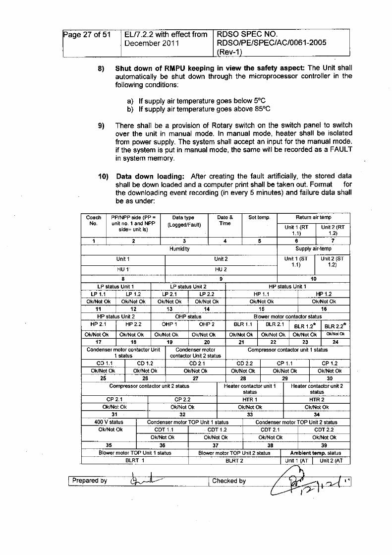
10) Data down loading: After creating the fault artificially, the stored datashall be down loaded and a computer print shall be taken out. Format forthe downloading event recording (in every 5 minutes) and failure data shallbe as under:
Coach PP/NPP side (PP = Data type Date & Set temp. Return air tempNo. unit no. 1 and NPP (Logged/Fault) Time
side= unit is) Unit 1 (RT Unit 2 (RT1.1 ) 1.2)
1 2 3 4 5 6 7
Humidity Supply air-temp
Unit 1 Unit2 Unit 1 (ST Unit 2 (ST
HU 1 HU21.1 ) 1.2)
8 9 10
LP status Unit 1 LP status Unit 2 HP status Unit 1
LP 1.1 LP 1.2 LP 2.1 LP 2.2 HP 1.1 HP 1.2Ok/Not Ok Ok/Not Ok Ok/Not Ok Ok/Not Ok Ok/Not Ok Ok/Not Ok
11 12 13 14 15 16
HP status Unit 2 OHP status Blower motor contactor statusHP 2.1 HP2.2 OHP 1 OHP2 BLR 1.1 BLR 2.1 BLR 1.2* BLR2.2*
Ok/Not Ok Ok/Not Ok Ok/Not Ok Ok/Not Ok Ok/Not Ok Ok/Not Ok Ok/Not Ok Ok/Not Ok
17 18 19 20 21 22 23 24
Condenser motor contactor Unit Condenser motor Compressor contactor unit 1 status1 status contactor Unit 2 status
CD 1.1 CD 1.2 CD2.1 CD2.2 CP 1.1 CP 1.2Ok/Not Ok Ok/Not Ok Ok/Not Ok Ok/Not Ok Ok/Not Ok Ok/Not Ok
25 26 27 28 29 30
Compressor contactor unit 2 status Heater contactor unit 1 Heater contactor unit 2status status
CP 2.1 CP2.2 HTR 1 HTR2Ok/Not Ok Ok/Not Ok Ok/Not Ok Ok/Not Ok
31 32 33 34
400 V status Condenser motor TOP Unit 1 status Condenser motor TOP Unit 2 statusOk/Not Ok COT 1.1 COT 1.2 COT 2.1 COT 2.2
Ok/Not Ok Ok/Not Ok Ok/Not Ok Ok/Not Ok
35 36 37 38 39Blower motor TOP Unit 1 status Blower motor TOP Unit 2 status I Ambient temp. status
BLRT 1 BLRT 2 I Unit 1 (AT I Unit 2 (AT
I Prepared by I Checked by
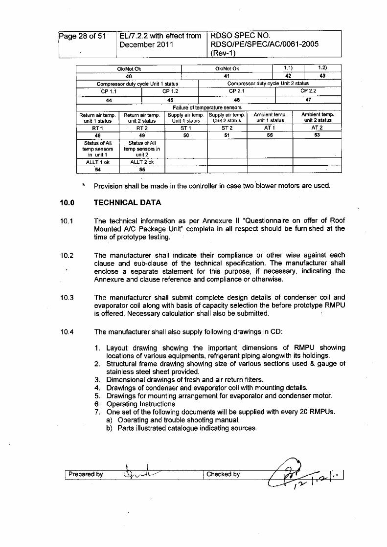
Page 28 of 51 EL/7.2.2 with effect from RDSO SPEC NO.December 2011 RDSO/PE/SPEC/AC/0061-2005
(Rev-1)
Ok/Not Ok I Ok/Not Ok I 1.1 ) I 1.2)
40 I 41 I 42 I 43
Compressor duty cycle Unit 1 status Compressor duty cycle Unit 2 statusCP 1.1 I CP 1.2 CP2.1 I CP2.2
44 I 45 46 I 47
Failure of temperature sensorsReturn air temp. Return air temp. Supply air temp. Supply air temp. Ambient temp. Ambient temp.
unit 1 status unit 2 status Unit 1 status Unit 2 status unit 1 status unit 2 statusRT1 RT2 ST 1 ST2 AT1 AT248 49 50 51 55 53
Status of All Status of Alltemp sensors temp sensors in
in unit 1 unit 2ALLT 10k ALLT2 ok
54 55
10.1 The technical information as per Annexure II "Questionnaire on offer of RoofMounted Ale Package Unit" complete in all respect should be furnished at thetime of prototype testing.
10.2 The manufacturer shall indicate their compliance or other wise against eachclause and sub-clause of the technical specification. The manufacturer shallenclose a separate statement for this purpose, if necessary, indicating theAnnexure and clause reference and compliance or otherwise.
10.3 The manufacturer shall submit complete design details of condenser coil andevaporator coil along with basis of capacity selection the before prototype RMPUis offered. Necessary calculation shall also be submitted.
1. Layout drawing showing the important dimensions of RMPU showinglocations of various equipments, refrigerant piping alongwith its holdings.
2. Structural frame drawing showing size of various sections used & gauge ofstainless steel sheet provided.
3. Dimensional drawings of fresh and air return filters.4. Drawings of condenser and evaporator coil with mounting details.5. Drawings for mounting arrangement for evaporator and condenser motor.6. Operating Instructions7. One set of the following documents will be supplied with every 20 RMPUs.
a) Operating and trouble shooting manual.b) Parts illustrated catalogue indicating sources.
I Prepared by I Checked by
Page 29 of 51 EU7.2.2 with effect from ROSO SPEC NO.December 2011 RDSO/PE/SPEC/AC/0061-2005
(Rev-1)
11.1 The general maintenance requirement for the unit should be of cleaning of filtersand blowing of dust etc. from the unit. The requirement for greasing should notbe earlier than 18 months. However, the firm will submit the recommendations onmaintenance requirement of RMPU, which should contain periodicity, workcontent and justification for each maintenance requirement.
12.1 Guarantee/warranty obligation of the equipments shall be as per IRS condition ofcontract.
13.1 Indian Railways shall not be responsible for infringement of patent rights arisingdue to similarity in design, manufacturing process, use of similar components inthe design & development of this item and any other factor not mentioned hereinwhich may cause such a dispute. The entire responsibility to settle any suchdisputes/matters lies with the manufacturer/ supplier.
Details / design/documents given by them are not infringing any IPR and they areresponsible in absolute and full measure instead of railways for any suchviolations. Data, specifications and other IP as generated out of interaction withrailways shall not be unilaterally used without the consent of ROSa and right ofRailways / ROSa on such IP is acceptable to them.
14.1 The contractor shall undertake to train, free of cost, the supervisors & staff of theIndian Railways for operation, maintenance, fault finding, trouble shooting, repairof the offered RMPUs under the guidance of the skilled engineers as and whenasked for by Railways.
The manufacturer shall be required to make available the services of hisengineers free of cost to monitor performance of the equipment in serviceperiodically and also carry necessary repairs or replacement under warrantyobligations. The necessary spares needed for replacement during service shouldbe available with the service engineers at all the possible places where thesecoaches are maintained.
I Prepared by clJ~~-----1Checked by
Page 30 of 51 ELI7 .2.2 with effect from RDSO SPEC NO.December 2011 RDSO/PE/SPEC/AC/0061-2005
(Rev-1)
17.1 The firms will not engage in cartel formation with other firms and will also submita declaration in this regard as per annexure III attached.
Proforma against cartel formation to be furnishedby the manufacturer
1) ROSO drawing No. ROSO/PE/SKIAC/0069 - 2004 (Rev 1) - Roof MountedAC Package Unit for LHB variant AC coaches (General arrangement &dimensional requirements)
2) ROSO drawing No. ROSO/PE/SKIAC/0125-2009 (Rev 1) - Switch panel forRMPU (LHB & double decker AC coaches)
3) ROSO drawing No. ROSO/PE/SKIAC/0071-2004 (Rev 1) - Air conditioningsystem for RMPU (LHB variant AC coaches)
4) ROSO drawing No. ROSO/PE/SKIAC/0072-2004 (Rev 1) - Wiring diagramof RMPU (LHB variant AC coaches)
5) RCF drawing No. SKEO-625 - Modified wiring diagram for Roof MountedAC Package Unit
6) HFG drawing No. S65F-100.900-00A.S4 (in seven sheets) for wiring onelectrical box (-X1, -X2, -X3 & -X4)-For relevant reference of wires andconnectors as per requirement of the specification.
7) . HFG drawing No. (3)11.0788-101-61 (in seven sheets) for relevantreferences of control wiring.
I Prepared by I Checked by
Page 31 of 51 ELI7.2.2 with effect from RDSO SPEC NO.December 2011 RDSO/PE/SPEC/AC/0061-2005
(Rev-1)
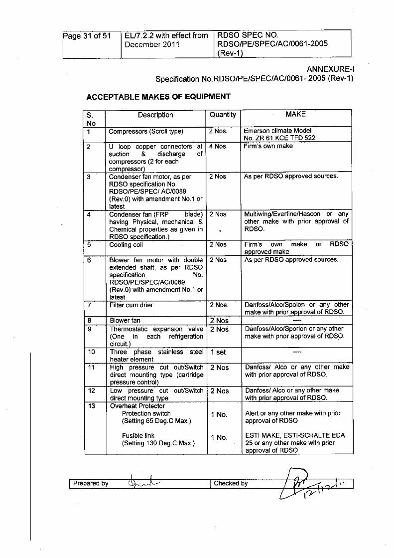
ANNEXURE-ISpecification NO.RDSO/PE/SPEC/AC/0061- 2005 (Rev-1)
ACCEPTABLE MAKES OF EQUIPMENT
S. Description Quantity MAKENo1 Compressors (Scroll type) 2 Nos. Emerson climate Model
No. ZR 61 KCE TFO 5222 U loop copper connectors at 4 Nos. Firm's own make
suction & discharge ofcompressors (2 for eachcompressor)
3 Condenser fan motor, as per 2 Nos As per ROSa approved sources.ROSa specification No.ROSa/PE/SPECI AC/0089(Rev.O) with amendment NO.1 orlatest
4 Condenser fan (FRP blade) 2 Nos Multiwing/Everfine/Hascon or anyhaving Physical, mechanical & other make with prior approval ofChemical properties as given in . ROSa .Rosa specification.)
5 Cooling coil 2 Nos Firm's own make or ROSaapproved make
6 Blower fan motor with double 2 Nos As per ROSa approved sources.extended shaft, as per ROSaspecification No.ROSa/PE/SPECI AC/0089(Rev.O) with amendment NO.1 orlatest
7 Filter cum drier 2 Nos. Oanfoss/Alco/Spolon or any othermake with prior approval of ROSa.
8 Blower fan 2 Nos . .. .•--
9 Thermostatic expansion valve 2 Nos Oanfoss/Alco/Sporlon or any other(ane in each refrigeration make with prior approval of ROSa.circuit. )
10 Three phase stainless steel 1 set ----
heater element11 High pressure cut out/Switch 2 Nos Oanfossl Alco or any other make
direct mounting type (cartridge with prior approval of ROSa.pressure control)
12 Low pressure cut out/Switch 2 Nos Oanfossl Alco or any other makedirect mounting type with prior approval of ROSa.
13 Overheat ProtectorProtection switch 1 No. Alert or any other make with prior(Setting 65 Oeg.C Max.) approval of ROSa
Fusible link 1 No. ESTI MAKE, ESTI-SCHAL TE EOA(Setting 130 Oeg.C Max.) 25 or any other make with prior
approval of ROSa
I Prepared by I Checked by
Page 32 of 51 ELfi.2.2 with effect from RDSO SPEC NO.December 2011 RDSO/PE/SPEC/AC/0061-2005
(Rev-1)
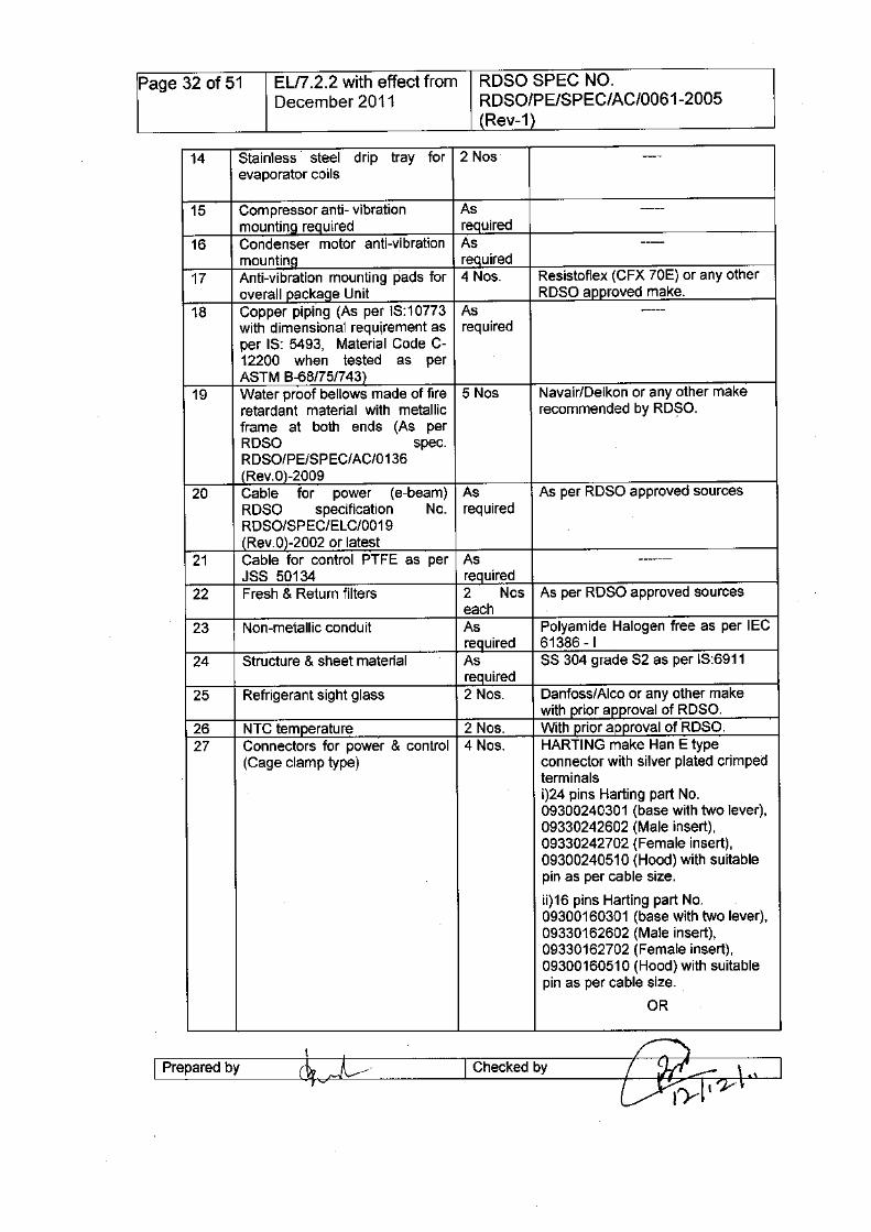
14 Stainless steel drip tray for 2 Nos ----evaporator coils
15 Compressor anti- vibration As -----mountina required required
16 Condenser motor anti-vibration As ----mountina required
17 Anti-vibration mounting pads for 4 Nos. Resistoflex (CFX 70E) or any otheroverall package Unit ROSO approved make.
18 Copper piping (As per IS:10773 As -----with dimensional requirement as requiredper IS: 5493, Material Code C-12200 when tested as perASTM 8-68/75/743)
19 Water proof bellows made of fire 5 Nos Navair/Oelkon or any other makeretardant material with metallic recommended by RO~O.frame at both ends (As perROSO spec.ROSO/PE/SPEC/AC/0136(Rev.0)-2009
20 Cable for power (e-beam) As As per ROSO approved sourcesROSO specification No. requiredROSO/SPEC/ELC/0019(Rev.0)-2002 or latest
21 Cable for control PTFE as per As -------JSS 50134 required
22 Fresh & Return filters 2 Nos As per ROSO approved sourceseach
23 Non-metallic conduit As Polyamide Halogen free as per IECrequired 61386 -I
24 Structure & sheet material As SS 304 grade S2 as per IS:6911required
25 Refrigerant sight glass 2 Nos. Oanfoss/Alco or any other makewith prior approval of ROSO.
26 NTC temperature 2 Nos. With prior approval of ROSO.27 Connectors for power & control 4 Nos. HARTl NG make Han E type
(Cage clamp type) connector with silver plated crimpedterminalsi)24 pins Harting part No.09300240301 (base with two lever),09330242602 (Male insert),09330242702 (Female insert),09300240510 (Hood) with suitablepin as per cable size.
ii)16 pins Harting part No.09300160301 (base with two lever),09330162602 (Male insert),09330162702 (Female insert),09300160510 (Hood) with suitablepin as per cable size.
OR
I Prepared by et:l/----I Checked by
Page 33 of 51 ELI7.2.2 with effect from RDSO SPEC NO.December 2011 RDSO/PE/SPEC/AC/0061-2005
(Rev-1)
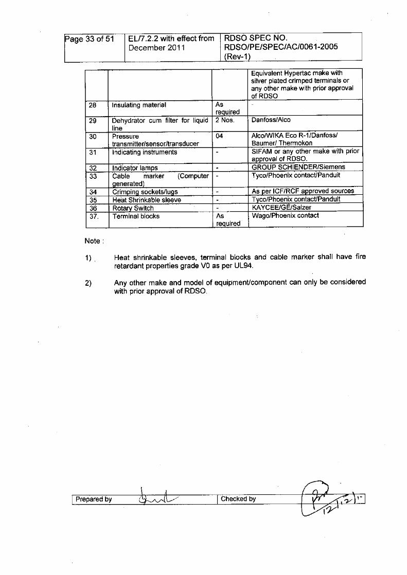
Equivalent Hypertac make withsilver plated crimped terminals orany other make with prior approvalofRDSo
28 Insulating material As -required
29 Dehydrator cum filter for liquid 2 Nos. Danfoss/Alcoline
30 Pressure 04 AlcolWlKA Eco R-1/Danfoss/transm itter/sensor/transd ucer Baumer/ Thermokon
31 Indicating instruments - SIFAM or any other make with priorapproval of RDSo.
32 Indicator lamps - GROUP SCHlENDER/Siemens33 Cable marker (Computer - Tyco/Phoenix contact/Panduit
Qenerated)34 CrimpinQ sockets/luQs - As per ICF/RCF approved sources35 Heat Shrinkable sleeve - Tyco/Phoenix contact/Panduit36 Rotary Switch - KAYCEE/GE/Salzer37. Terminal blocks As Wago/Phoenix contact
required
1) . Heat shrinkable sleeves, terminal blocks and cable marker shall have fireretardant properties grade va as per UL94.
2) Any other make and model of equipmenUcomponent can only be consideredwith prior approval of RDSa.
I Prepared by I Checked by
Page 34 of 51 ELI7.2.2 with effect from RDSO SPEC NO.December 2011 RDSO/PE/SPEC/AC/0061-2005
(Rev-1)
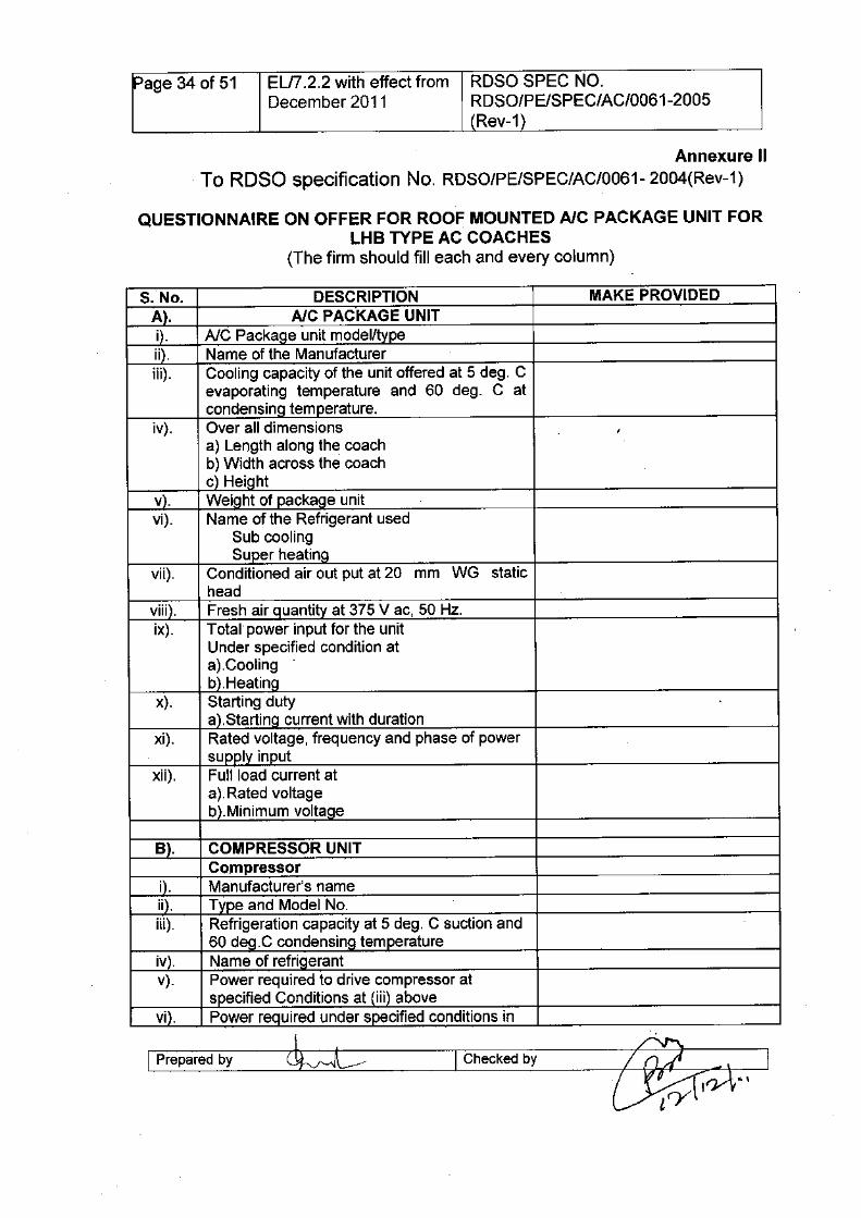
Annexure IITo RDSa specification No. RDSO/PE/SPEC/AC/0061- 2004(Rev-1)
QUESTIONNAIRE ON OFFER FOR ROOF MOUNTED AlC PACKAGE UNIT FORLHB TYPE AC COACHES
(The firm should fill each and every column)
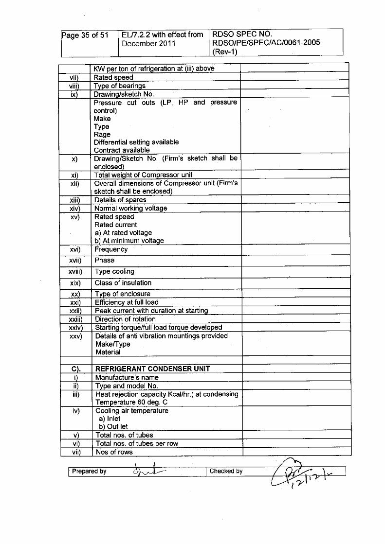
S. No. DESCRIPTION MAKE PROVIDEDA). AlC PACKAGE UNITi). AlC Package unit model/typeii). Name of the Manufactureriii). Cooling capacity of the unit offered at 5 deg. C
evaporating temperature and 60 deg. C atcondensing temperature.
iv). Over all dimensions ,a) Length along th~ coachb) Width across the coachc) Height
v). Weight of package unitvi). Name of the Refrigerant used
Sub coolingSuper heating
vii). Conditioned air out put at 20 mm WG statichead
viii). Fresh air quantity at 375 V ac, 50 Hz.ix). Total" power input for the unit
Under specified condition ata).Coolingb).Heating
x). Starting dutya).Starting current with duration
xi). Rated voltage, frequency and phase of powersupply input
xii). Full load current ata).Rated voltageb).Minimum voltage
B). COMPRESSOR UNITCompressor
i). Manufacturer's nameii). Type and Model No.iii). Refrigeration capacity at 5 deg. C suction and
60 deg.C condensing temperatureiv). Name of refrigerantv). Power required to drive compressor at
specified Conditions at (iii) abovevi). Power reauired under specified conditions in
I Prepared by I Checked by
" .
~ ..
Page 35 of 51 EU7.2.2 with effect from ROSa SPEC NO.December 2011 RDSO/PE/SPEC/AC/0061-2005
(Rev-1 )
KW per ton of refrigeration at (iii) abovevii) Rated speedviii) Type of bearingsix) Drawing/sketch No.
Pressure cut outs (LP, HP and pressurecontrol)MakeTypeRageDifferential setting availableContract available
x) Drawing/Sketch No. (Firm's sketch shall beenclosed)
xi) Total weight of Compressor unitxii) Overall dimensions of Compressor unit (Firm's
sketch shall be enclosed)xiii) Details of sparesxiv) Normal workino voltaoexv) Rated speed
Rated currenta) At rated voltageb) At minimum voltaoe
xVi) Frequency
xVii) Phase
xviii) Type cooling
xix) Class of insulation
xx) Type of enclosurexxi) Efficiency at full loadxxii) Peak current with duration at startinoxxiii) Direction of rotationxxiv) Startino torQue/full load torque developedxxv) Details of anti vibration mountings provided
MakelTypeMaterial
C). REFRIGERANT CONDENSER UNITi Manufacture's nameii) Type and model No.iii) Heat rejection capacity Kcal/hr.) at condensing
Temperature 60 deo. Civ) Cooling air temperature
a) Inletb) Out let
v Total nos. of tubesvi Total nos. of tubes per rowvii Nos of rows
I Prepared by I Checked by ~\_V'
EL/7.2.2with effect fromDecember 2011
RDSO SPEC NO.RDSO/PE/SPEC/AC/0061-2005Rev-1
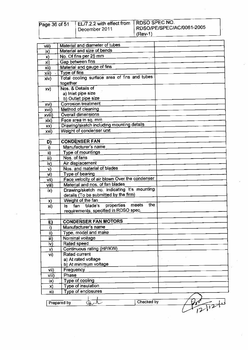
viii) Material and diameter of tubesix Material and size of bendsx No. Of fins per 25 mmxi Gap between finsxii) Material and QauQe of finsxiii Type of finsxiv) Total cooling surface area of fins and tubes
togetherxv) Nos. & Details of
a) Inlet pipe sizeb) Outlet pipe size
xvi) Corrosion treatmentxvii Method of cleaningxviii) Overall dimensionsxix Face area in sq. mmxx Drawing/sketch including mounting detailsxxi) Weight of condenser unit
D CONDENSER FANi Manufacturer's nameii) Type of mountingsiii Nos. of fansiv Air displacementv) Nos. and material of bladesvi' Type of bearingvii Face velocity of air blown Over the condenserviii I Material and nos. of fan bladesix) Drawing/sketch no. indicating it's mounting
details (To be submitted by the firm)x) WeiQht of the fanxi) Is fan blade's properties meets the
requirements, specified in RDSO spec.
E CONDENSER FAN MOTORSi Manufacturer's nameii Type, model and makeiii Nominal voltageiv Rated speedv Continuous rating (HP/KW)vi) Rated current
a) At rated voltageb) At minimum voltage
vii) Frequencyviii) Phaseix) Type of coolingx) Type of insulationxi Type of enclosures
I I /~I Prepared by ~A I Checked by / f;kf' __ I.J
~y\I'Y\
Page 37 of 51 EL/7.2.2 with effect from RDSO SPEC NO.December 2011 RDSO/PE/SPEC/AC/0061-2005
(Rev-1)
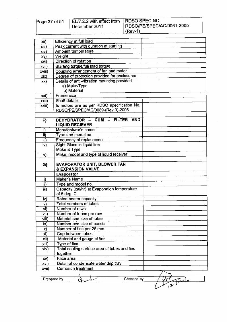
xii Efficiency at full loadxiii) Peak current with duration at startingxiv Ambient temperaturexv Weightxvi Direction of rotationxvii) Starting torQue/fullload torquexviii) Coupling arrangement of fan and motorxix Degree of protection provided for enclosuresxx) Details of anti-vibration mounting provided
a) MakelTypeb) Material
xxi Frame sizexxii Shaft details /
XXiii) Is motors are as per RDSO specification No.RDSO/PE/SPEC/AC/0089-(Rev.O)-2008
F) DEHYDRATOR - CUM - FILTER ANDLIQUID RECIEVER
i Manufacturer's nameii Type and model no.iii Frequency of replacementiv) Sight Glass in liquid line
Make & Typev) Make, model and type of liquid receiver
G) EVAPORATOR UNIT, BLOWER FAN& EXPANSION VALVEEvaporator
i) Maker's Nameii) Type and model no.iii) Capacity (cal/hr) at Evaporation temperature
of 5 deg. Civ Rated heater capacityv Total numbers of tubes .
vi Number of rowsvii) Number of tubes per rowviii) Material and size of tubesix Number and size of bendsx Number of fins per 25 mmxi Gap between tubesxii Material and gauge of finsxiii) Type of finsxiv) Total cooling surface area of tubes and fins
togetherxv Face areaxvi Detail of condensate water drip trayxviiI Corrosion treatment
I Prepared by I Checked by ~I_t~ _
Page 38 of 51 ELI? .2.2 with effect from RDSO SPEC NO.December 2011 RDSO/PE/SPEC/AC/0061-2005
(Rev-1)
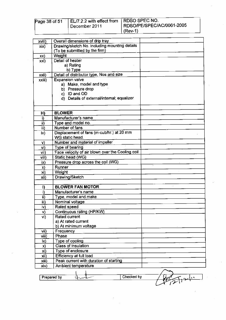
xviii Overall dimensions of drip trayxix) Drawing/sketch No. including mounting details
(To be submitted by the firm)xx) WeightxXi) Detail of heater
a) Ratingb) Type
xxii) Detail of distributor type, Nos and sizexxiii) Expansion valve
a) Make, model and typeb) Pressure dropc) ID and ODd) Details of external/internal; equalizer
H BLOWERi Manufacturer's nameii Type and model no.iii) Number of fansiv) Displacement of fans (m-cub/hr.) at 20 mm
WG static head.v Number and material of impellervi Type of bearingvii Face velocity of air blown over the Cooling coilviii Static head (WG)ix) Pressure drop across the coil (wG)x Runnerxi Weightxii) Drawino/Sketch
I BLOWER FAN MOTORi Manufacturer's nameii Type, model and makeiii Nominal voltaoeiv Rated speedv Continuous rating (HP/KW)vi) Rated current
a) At rated currentb) At minimum voltage
vii) Frequencyviii Phaseix) Type of coolingx Class of insulationxi Type of enclosurexii Efficiency at full loadxiii Peak current with duration of startingxiv Ambient temperature
l-p-re-p-ar-ed-bY---~- I Checkedby
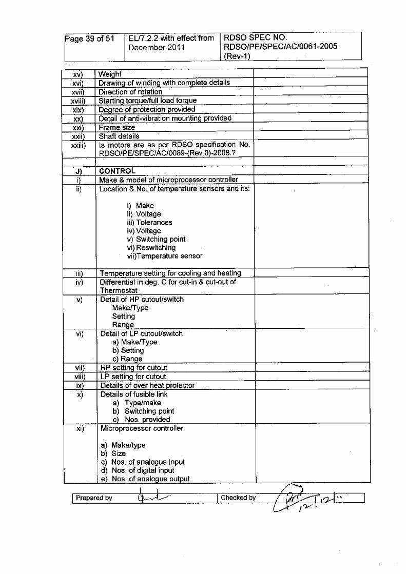
Page 39 of 51 ELI7.2.2 with effect"from RDSO SPEC NO.December 2011 RDSO/PE/SPEC/AC/0061-2005
(Rev-1)
xv Weightxvi Drawino of windino with complete detailsxvii Direction of rotationxviii Startino torque/full load torquexix Deoree of protection providedxx Detail of anti-vibration mounting providedxxi Frame sizexxii) Shaft detailsxxiii) Is motors are as per RDSO specification No.
RDSO/PE/SPEC/AC/0089-(Rev. 0)-2008.?
J) CONTROLi) Make & model of microprocessor controllerii) Location & No. of temperature sensors and its:
i) Makeii) Voltageiii) Tolerancesiv)Voltagev) Switching pointvi) Reswitchingvii)Temperature sensor
iii) Temperature settino for cooling and heatingiv) Differential in deg. C for cut-in & cut-out of
Thermostatv) Detail of HP cutout/switch
MakelTypeSettingRanoe
vi) Detail of LP cutout/switcha) MakelTypeb) Settingc) Ranoe
vii) HP setting for cutoutviii) LP setting for cutoutix) Details of over heat protectorx) Details of fusible link
a) Type/makeb) Switching pointc) Nos. provided
xi) Microprocessor controller
a) Make/typeb) Sizec) Nos. of analogue inputd) Nos. of digital inpute) Nos. of analogue output
I I /"'JI Prepared by ~..-/ I Checked by / 1'If';..--r" I~ ' • IL.--Y I'}/ L
Page 40 of 51 ELn.2.2 with effect from RDSO SPEC NO.December 2011 RDSO/PE/SPEC/AC/0061-2005
(Rev-1)
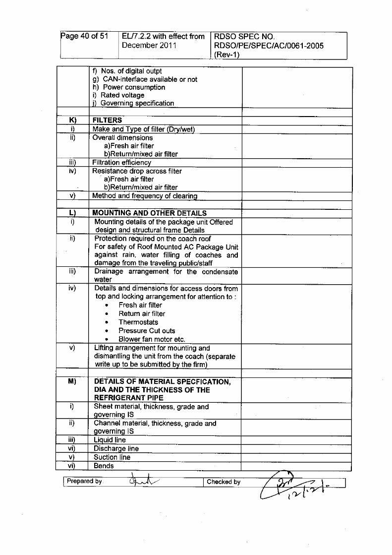
f) Nos. of digital outptg) CAN-interface available or noth) Power consumptioni) Rated voltagej) GoverninQ specification
K) FILTERSi) Make and Type of filter (Dry/wet)ii) Overall dimensions
a)Fresh air filterb)Return/mixed air filter
Hi) Filtration efficiencyiv) Resistance drop across filter
a)Fresh air filterb)Return/mixed air filter
v) Method and frequency of clearinQ
L) MOUNTING AND OTHER DETAILSi) Mounting details of the package unit Offered
design and structural frame Detailsii) Protection required on the coach roof
For safety of Roof Mounted AC Package Unitagainst rain, water filling of coaches anddamaQe from the travelinQ public/staff
iii) Drainage arrangement for the condensatewater
iv) Details and dimensions for access doors fromtop and locking arrangement for attention to :
• Fresh air filter• Return air filter• Thermostats• Pressure Cut outs• Blower fan motor etc.
v) Lifting arrangement for mounting anddismantling the unit from the coach (separatewrite UP to be submitted by the firm)
M) DETAILS OF MATERIAL SPECFICATION,DIA AND THE THICKNESS OF THEREFRIGERANT PIPE
i) Sheet material, thickness, grade andgoverning IS
ii) Channel material, thickness, grade andgoverning IS
iii) Liquid linevi) Discharge linev) Suction linevi) Bends
\ j / '\I Prepared by (~- .1\/ I Checked by / .?rt'~ .l •• I
~rv[\'Y •
Page 41 of 51 ELI7.2.2 with effect from RDSO SPEC NO.December 2011 RDSO/PE/SPEC/AC/OO61-2005
(Rev-1)
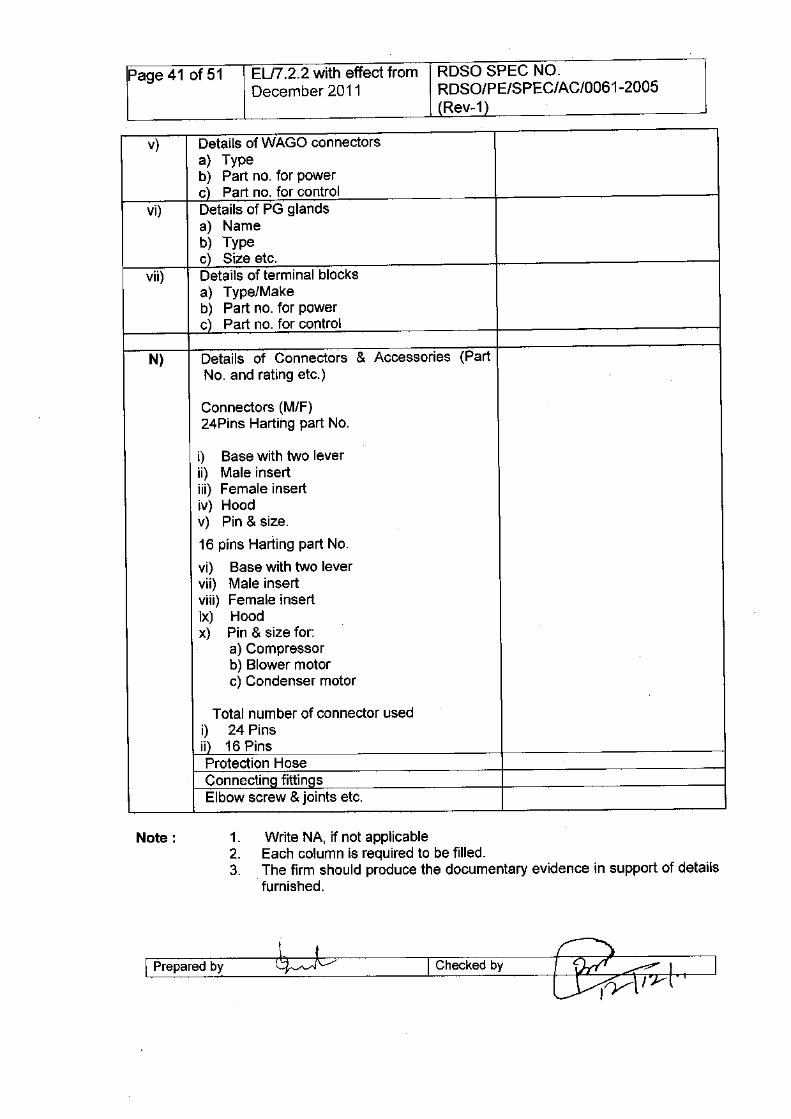
v) Details of WAGO connectorsa) Typeb) Part no. for powerc) Part no. for control
vi) Details of PG glandsa) Nameb) Typec) Size etc.
vii) Details of terminal blocksa) Type/Makeb) Part no. for powerc) Part no. for control
N) Details of Connectors & Accessories (PartNo. and rating etc.)
Connectors (M/F)24Pins Harting part No.
i) Base with two leverii) Male insertHi) Female insertiv) Hoodv) Pin & size.
16 pins Harting part No.
vi) Base with two levervii) Male insertviii) Female insertix) Hoodx) Pin & size for:
a) Compressorb) Blower motorc) Condenser motor
Total number of connector usedi) 24 Pinsii) 16 PinsProtection HoseConnectinQ fittinQsElbow screw & joints etc.
1. Write NA, if not applicable2. Each column is required to be filled.3. The firm should produce the documentary evidence in support of details
furnished.
I Prepared by I Checked by
Page 42 of 51 EL/7.2.2 with effect from RDSO SPEC NO.December 2011 RDSO/PE/SPEC/AC/0061-2005
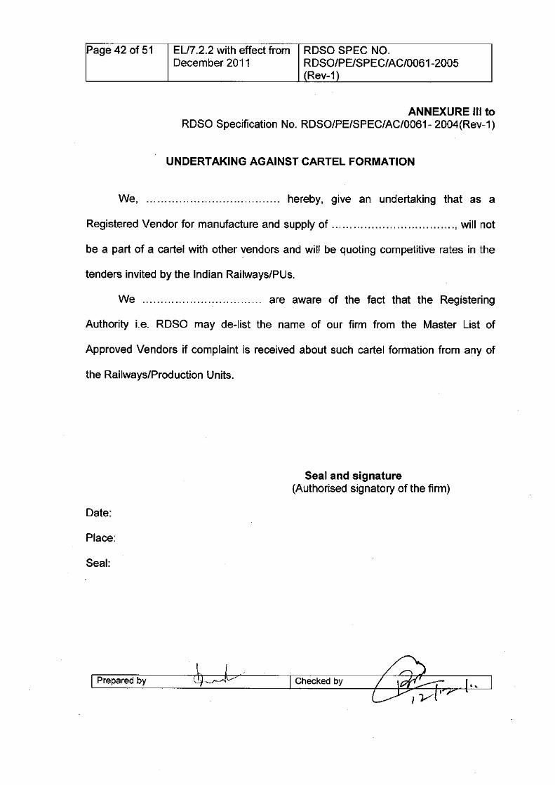
(Rev-1)
ANNEXURE III toRDSO Specification No. RDSO/PE/SPEC/AC/0061- 2004(Rev-1)
Seal and signature(Authorised signatory of the firm)
I Prepared by I Checked by
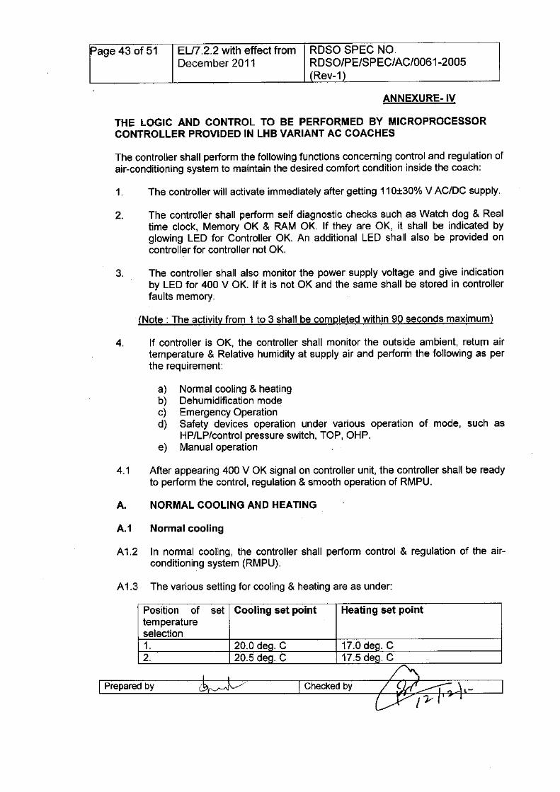
Page 43 of 51 ELI7.2.2 with effect from RDSO SPEC NO.December 2011 RDSO/PE/SPEC/AC/0061-2005
(Rev-1)
THE LOGIC AND CONTROL TO BE PERFO~MED BY MICROPROCESSORCONTROLLER PROVIDED IN LHB VARIANT AC COACHES
The controller shall perform the following functions concerning control and regulation ofair-conditioning system to maintain the desired comfort condition inside the coach:
2. The controller shall perform self diagnostic checks such as Watch dog & Realtime clock, Memory OK & RAM OK. If they are OK, it shall be indicated byglowing LED for Controller OK. An additional LED shall also be provided oncontroller for controller not OK.
3. The controller shall also monitor the power supply voltage and give indicationby LED for 400 V OK. If it is not OK and the same shall be stored in controllerfaults memory.
4. If controller is OK, the controller shall monitor the outside ambient, return airtemperature & Relative humidity at supply air and perform the following as perthe requirement:
a) Normal cooling & heatingb) Dehumidification modec) Emergency Operationd) Safety devices operation under various operation of mode, such as
HP/LP/control pressure switch, TOP, OHP.e) Manual operation
4.1 After appearing 400 V OK signal on controller unit, the controller shall be readyto perform the control, regulation & smooth operation of RMPU.
A1.2 In normal cooling, the controller shall perform control & regulation of the air-conditioning system (RMPU).
Position oftemperatureselection1.2.
I Prepared by I Checked by
20.0 de . C20.5 de . C
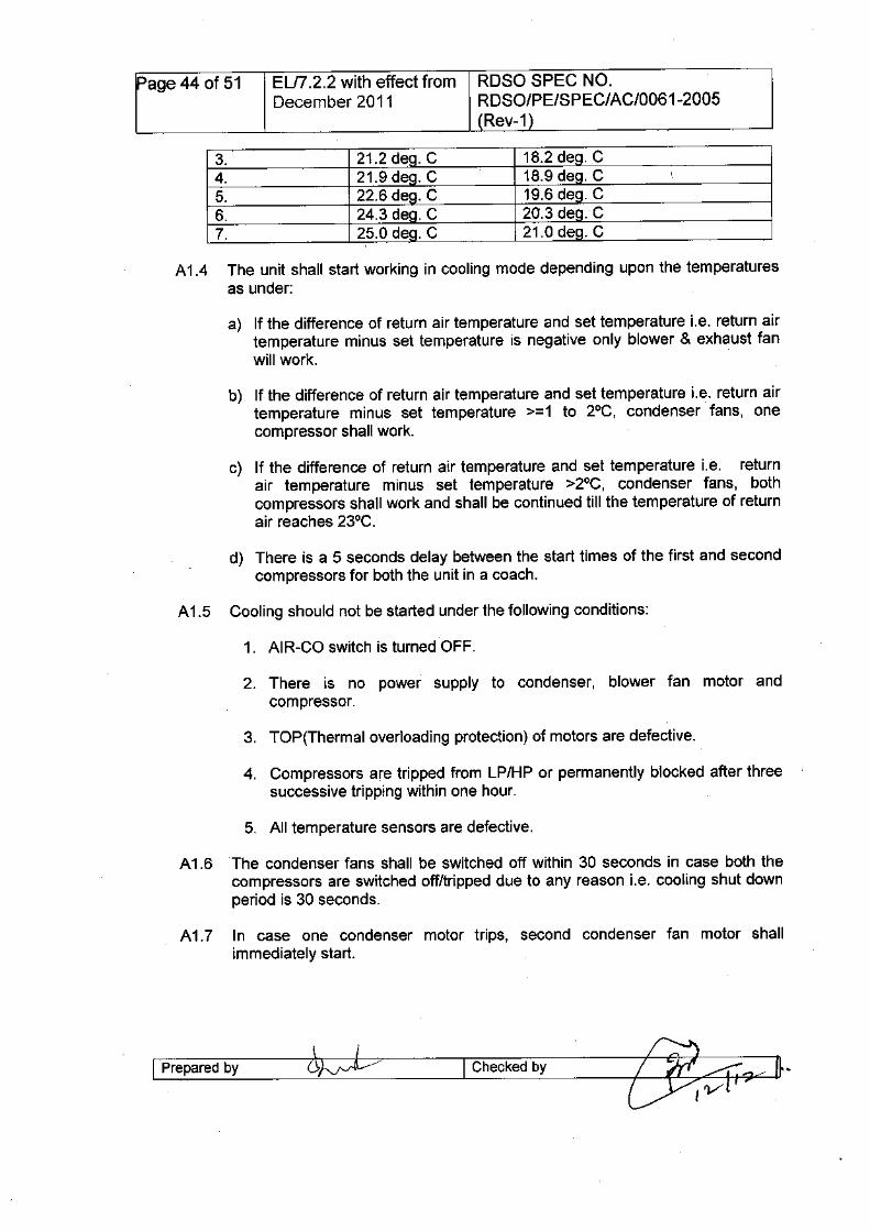
Page 44 of 51 EU7.2.2 with effect from ROSa SPEC NO.December 2011 RDSO/PE/SPEC/AC/0061-2005
(Rev-1)
3. 21.2 de . C4. 21.9 de . C5. 22.6 de . C6. 24.3 de . C7. 25.0 de . C
A 1.4 The unit shall start working in cooling mode depending upon the temperaturesas under:
a) If the difference of return air temperature and set temperature Le. return airtemperature minus set temperature is negative only blower & exhaust fanwill work.
b) If the difference of return air temperature and set temperature Le. return airtemperature minus set temperature >=1 to 2°C, condenser fans, onecompressor shall work.
c) If the difference of return air temperature and set temperature Le. returnair temperature minus set temperature >2°C, condenser fans, bothcompressors shall work and shall be continued till the temperature of returnair reaches 23°C.
d) There is a 5 seconds delay between the start times of the first and secondcompressors for both the unit in a coach.
2. There is no power supply to condenser, blower fan motor andcompressor.
4. Compressors are tripped from LP/HP or permanently blocked after threesuccessive tripping within one hour.
A1.6 The condenser fans shall be switched off within 30 seconds in case both thecompressors are switched off/tripped due to any reason Le. cooling shut downperiod is 30 seconds.
A 1.7 In case one condenser motor trips, second condenser fan motor shallimmediately start.
I Prepared by 6;vvb~---1Checked by
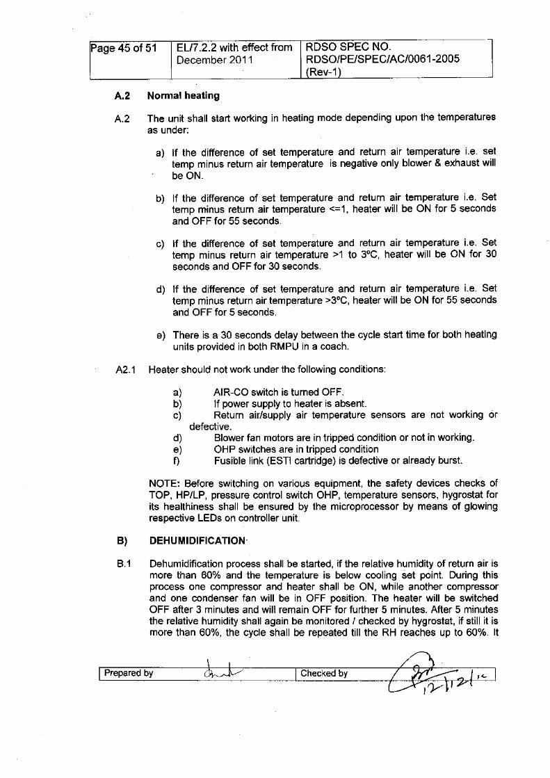
Page 45 of 51 EL/7.2.2 with effect from RDSO SPEC NO.December 2011 RDSO/PE/SPEC/AC/0061-2005
(Rev-1)
A.2 The unit shall start working in heating mode depending upon the temperaturesas under:
a) If the difference of set temperature and return air temperature i.e. settemp minus return air temperature is negative only blower & exhaust willbe ON.
b). If the difference of set temperature and return air temperature i.e. Settemp minus return air temperature <=1, heater will be ON for 5 secondsand OFF for 55 seconds.
c) If the difference of set temperature and return air temperature i.e. Settemp minus return air temperature >1 to 3°C, heater will be ON for 30seconds and OFF for 30 seconds.
d) If the difference of set temperature and return air temperature i.e. Settemp minus return air temperature >3°C, heater will be ON for 55 secondsand OFF for 5 seconds.
e) There is a 30 seconds delay between the cycle start time for both heatingunits provided in both RMPU in a coach.
a) AIR-CO switch is turned OFF.b) If power supply to heater is absent.c) Return air/supply air temperature sensors are not working or
defective.d) Blower fan motors are in tripped condition or not in working.e) OHP switches are in tripped conditionf) Fusible link (ESTI cartridge) is defective or already burst.
NOTE: Before switching on various equipment, the safety devices checks ofTOP, HP/LP, pressure control switch OHP, temperature sensors, hygrostat forits healthiness shall be ensured by the microprocessor by means of glowingrespective LEOs on controller unit.
B.1 Dehumidification process shall be started, if the relative humidity of return air ismore than 60% and the temperature is below cooling set point. During thisprocess one compressor and heater shall be ON, while another compressorand one condenser fan will be in OFF position. The heater will be switchedOFF after 3 minutes and will remain OFF for further 5 minutes. After 5 minutesthe relative humidity shall again be monitored / checked by hygrostat, if still it ismore than 60%, the cycle shall be repeated till the RH reaches up to 60%. It
l-p-re-p-ar-ed-b-y----ck~=:Jc7 . I Checkedby
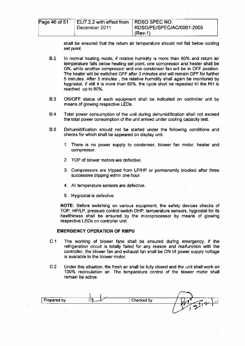
Page 46 of 51 EU7.2.2 with effect from RDSO SPEC NO.December 2011 RDSO/PE/SPEC/AC/0061-2005
(Rev-1)
shall be ensured that the return air temperature should not fall below coolingset point.
B.2 In normal heating mode, if relative humidity is more than 60% and return airtemperature falls below heating set point, one compressor and heater shall beON, while another compressor and one condenser fan will be in OFF position.The heater will be switched OFF after 3 minutes and will remain OFF for further5 minutes. After 5 minutes , the relative humidity shall again be monitored byhygrostat,if still it is more than 60%, the cycle shall be repeated till the RH isreached up to 60%.
B.3 ON/OFF status of each equipment shall be indicated on controller unit bymeans of glowing respective LEOs.
B.4 Total power consumption of the unit during dehumidification shall not exceedthe total power consumption of the unit arrived under cooling capacity test.
B.5 Dehumidification should not be started under the following conditions andchecks for which shall be appeared on display unit:
1. There is no power supply to condenser, blower fan motor, heater andcompressor.
3. Compressors are tripped from LP/HP or permanently blocked after threesuccessive tripping within one hour.
NOTE: Before switching on various equipment, the safety devices checks ofTOP, HP/LP, pressure control switch OHP, temperature sensors, hygrostat for itshealthiness shall be ensured by the microprocessor by means of glowingrespective LEOs on controller unit.
C.1 The working of blower fans shall be ensured during emergency, if therefrigeration circuit is totally failed for any reason and malfunction with thecontroller, the blower fan and exhaust fan shall be ON till power supply voltageis available to the blower motor.
C.2 Under this situation, the fresh air shall be fully closed and the unit shall work on100% recirculation air. The temperature control of the blower motor shallremain be active.
I-p-re-p-a-re-d-b-Y----~/ I Checkedby
Page 47 of 51 ELI7.2.2 with effect from ROSa SPEC NO.December 2011 RDSO/PE/SPEC/AC/0061-2005
(Rev-1)
1) Starting of compressors: Both the compressors shall not be started at atime. First compressor of each unit should be started after 30 seconds fromswitching ON of AIR-CO switch. Second compressors of the units shall bestarted after a delay of 5 seconds from start of first compressors, ifrequired.
2) High Pressure switches: The compressor should be switchedOFF/tripped, if discharge pressure of compressor rises beyond a limit of425±15psig. Once the compressor has been switched OFF, it shall not bestarted before 5 seconds even it is required.
If the compressor tripped three times in one hour, the fault shall bestored/displayed by means of glowing fault indication lamp provided onswitch panel, in addition to LED indi.cation.
In case both the compressors of any unit are switched OFF at a time, firstcompressor shall be started after 30seconds and other one after 5 secondsfrom start of first compressor.
The provision shall be there to restart the unit in case both the compressorshave tripped three times in one hour.
3) Low Pressure switches: The compressor should be switchedOFF/tripped, if suction pressure of compressor goes down beyond limit of35±15 psig. Once the compressor has been switched OFF, it shall not bestarted before 5 second even it is required.
If the compressor tripped three times in one hour, the fault shall bestored/displayed by means of glowing fault indication lamp provided onswitch panel, in addition to LED indication.
In case both the compressors of any unit are switched OFF at a time, firstcompressor shall be started after 30 minutes and other one after 5 secondsfrom start of first compressor.
The provisfon shall be there to restart the unit in case both the compressorshave tripped three times in one hour.
4) Control Pressure switch: Control pressure switches are provided in eachcircuit to monitor the discharge pressure of compressor. If the dischargepressure is below 275 psig, only one condenser fan will be in working. If thedischarge pressure rises above 275 psig, the second compressor shall bestarted (both condenser fans will run).
5) Thermal over load protection: Thermal overload protection devices areembedded in the winding of each motors, which allow to disconnect motorsupply through contactor, if the winding temperature of the motor rises
I Prepared by ~. I Checked by ~J_t. __~
Page 48 of 51 ELI7.2.2 with effect from RDSO SPEC NO.December 2011 RDSO/PE/SPEC/AC/0061-2005
(Rev-1)
130°C and shall be automatically re-started when the temperature of thewinding comes down. The message shall be displayed by means of LEDindication on controller unit.
If it happens three times in one hour, the fault shall be indicated by means offault indication lamp provided on switch panel in addition to LED indicationon controller unit.
(NOTE: The fault indication light prOVided on switch panel should be resetby turning of AIR-CO switch. The OFF time of motors under this conditionshall also be recorded /stored in memory of the controller.)
6) Over heat protection (OHP) for heater: During heating mode in winter,the overheat protection switch shall take care for excessive heating ofsupply air. If the supply air temperature reaches beyond the set value i.e.65°C due to any reason, the OHP will react immediately to disconnect thepower supply to the heater through controller and will block the heaterworking further. The blinking message shall be displayed for the same ondisplay unit. The heating facility shall be available only by re-switch ON ofAIR-CO switch. This event shall be recorded/stored in controller memorywith the time and at which temperature it has acted.
If for any reason, OHP does not act at 65°C and the temperature rises up to.85°C, the respective contactor of the heater shall be open throughmicroprocessor controller.
7) Shut down of RMPU keeping in view the safety aspect: The Unit shallautomatically be shut down through the microprocessor controller in thefollowing conditions:
a) If supply air temperature goes below 5°Cb) If supply air temperature goes above 85°C
There shall be the provision for a Rotary switch on the switch board cabinet toswitch over the unit in manual mode. In manual mode heater shall be isolatedfrom power supply. The system shall accept an input for the manual mode.
1. The microprocessor controller shall be compatible with NTC sensors & capacitivehygrostat.
2. The return air temperature shall be the average of both side return airtemperature being sensed by temperature sensors. In case, any sensor isdefective the reading shall be taken from healthy sensor. In case both thesensors have failed, the microprocessor controller will work on the temperature of
I Prepared by I Checked by
Page 49 of 51 EU7.2.2 with effect from RDSO SPEC NO.December 2011 RDSO/PE/SPEC/AC/0061-2005
(Rev-1)
fresh air sensor. Heating mode should not work if all temperature sensors aredefective.
3. The ambient temperature shall be the average of both side fresh airtemperatures being sensed by temperature sensor. In case, any sensor isdefective the reading shall be taken from healthy sensor.
4. The software should be window based and user friendly in common syntaxlanguage and should be able to import/export the fault failure reports or datalogging reports for further analysis.
5. The storage capacity of events recording shall be of 7 days. At least 2000 faultsshall be recorded. The facility for down loading of events and fault through USBdrive shall be ensured.
I Prepared by\ I /~v I Checked by
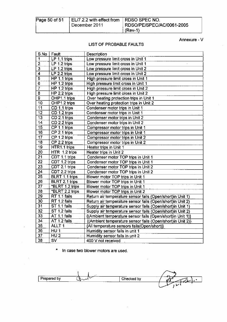
Page 50 of 51 EU7.2.2 with effect from RDSO SPEC NO.December 2011 RDSO/PE/SPEC/AC/0061-2005
(Rev-1)
S.No Fault Description1 LP 1.1 trips Low pressure limit cross in Unit 12 LP 1.2 trips Low pressure limit cross in Unit 13 LP 1.2 trips Low pressure limit cross in Unit 24 LP 2.2 trips Low pressure limit cross in Unit 25 HP 1.1 trips High pressure limit cross in Unit 16 HP 1.2 trips High pressure limit cross in Unit 17 HP 1.2 trips High pressure limit cross in Unit 28 HP 2.2 trips High pressure limit cross in Unit 29 OHP1.1 trips Over heating protection trips in Unit 110 OHP1.2 trips Over heating protection trips in Unit 211 CD 1.1 trips Condenser motor trips in Unit 112 CD 1.2 trips Condenser motor trips in Unit 113 CD 2.1 trips Condenser motor trips in Unit 214 CD 2.2 trips Condenser motor trips in Unit 215 CP 1.1 trips Compressor motor trips in Unit 116 CP 2.1 trips Compressor motor trips in Unit 117 CP 1.2 trips Compressor motor trips in Unit 218 CP 2.2 trips Compressor motor trips in Unit 219 HTR 1.1 trips Heater trips in Unit 120 HTR 1.2 trips Heater trips in Unit 221 COT 1.1 trips Condenser motor TOP trips in Unit 122 COT 1.2 trips Condenser motor TOP trips in Unit 123 COT 2.1 trips Condenser motor TOP trips in Unit 224 COT 2.2 trips Condenser motor TOP trips in Unit 225 BLRT 1.1 trips Blower motor TOP trips in Unit 126 BLRT 2.1 trips Blower motor TOP trips in Unit 127 *BLRT 1.2 trips Blower motor TOP trips in Unit 128 *BLRT 2.2 trips Blower motor TOP trips in Unit 229 RT 1.1 fails Return air temperature sensor fails IOpen/short in Unit 130 RT 1.2 fails Return air temperature sensor fails IOpen/short in Unit 231 ST 1.1 fails Supply air temperature sensor fails Open/short in Unit 132 ST 1.2 fails Supply air temperature sensor fails Open/short in Unit 233 AT 1.1 fails Ambient temperature sensor fails (Open/short in Unit 1 134 AT 1.2 fails (Ambient temperature sensor fails Open/short in Unit 2 Il35 ALLT 1 All temperature sensors fails(Open/short)}36 HU 1 Humidity sensor fails in unit 137 HU 2 Humidity sensor fails in unit 238 SV 400 V not received
I Prepared by I Checked by

Page 51 of 51 EU7.2.2 with effect from ROSO SPEC NO.December 2011 ROSO/PE/SPE C/AC/0061-2005
(Rev-1)
• Eastern Railway, Fairlie Place, Kolkata - 700 001 • ~~~~, 4l1C'fCllIC11700001
• Northern Railway, Baroda House, New Delhi-110 001 • "i.mR~,.~,~~-110001
• Central Railway, Parcel office, CST, Mumbai CST - 400 • lJUT,~ ~ ~-400 001001
• Northeast Frontier Railway, Maligaon, Guwahati -781 001 • ~~~,~,~-781001
• North Eastern Railway, Gorakhpur -273 001 • ~~, lJffiw-273001
• South Central Railway, Nilayam, Secunderabad - 500 371 • Gfa1ullJUT m ,t1"~ fflq;C;~I~IC; -500371
• Southern Railway, Park Town, Chennai -600 003 • Gfa1ulm wt CT\R, ~-600003
• South Eastern Railway, Garden Reach, Kolkata -700 • Gfa1ul~~~~,4l1C'fCllIC11 700043043
• Western Railway, Churchgate, Mumbai - 400 020 • ~TPf ~ W,~-400020
• North Central Railway, Subedarganj, Allahabad-211 033 • "i.mRlJUT~, '{j~c;I~li\J1,~C'f161~1C;211033
• Western Central Railway, Jabalpur-482 001 • WlJUT~, ~-482001
• East Central Railway, Dighi, Distt- Vashali, Hajipur, Bihar- • ~lJUT~fuft~~ rc;ll ~ ~ -844101844101
• North Western Railway, Jaipur 302006 • "i.mRW~, ~-302006
• South Western Railway, 4tn Floor, DRM office, Sh Laxmi • Gfa1ul~~, ~~ (fc'J , ~03lR0~0 ~ ~ c;r~Narayan Complex, Station Road, Hubli, - 580020
Tffil1M CIlISj~Cffi ~GRmsm*-580 020
• South East Central Railway, Bilaspur-495004 • Gfa1ul~ lJUTt1",~-495 004
• East Coast Railway, Bhuvneshwar Orrisa-751 016 • ~ m"~fAGCR ~ -751 016
Konkan Railway, Belapur Bhawan, Sector-11, Belapur, • ~~,~1Wl,m-11,~ ~-400614Mumbai - 400 614
• Integral Coach Factory, Chennai.-600038 • M~~,~-600038
• Rail Coach Factory, Hussainpur, Kapurthala-144602 • t1"~~,~,~~-144602
I Prepared by I Checked by
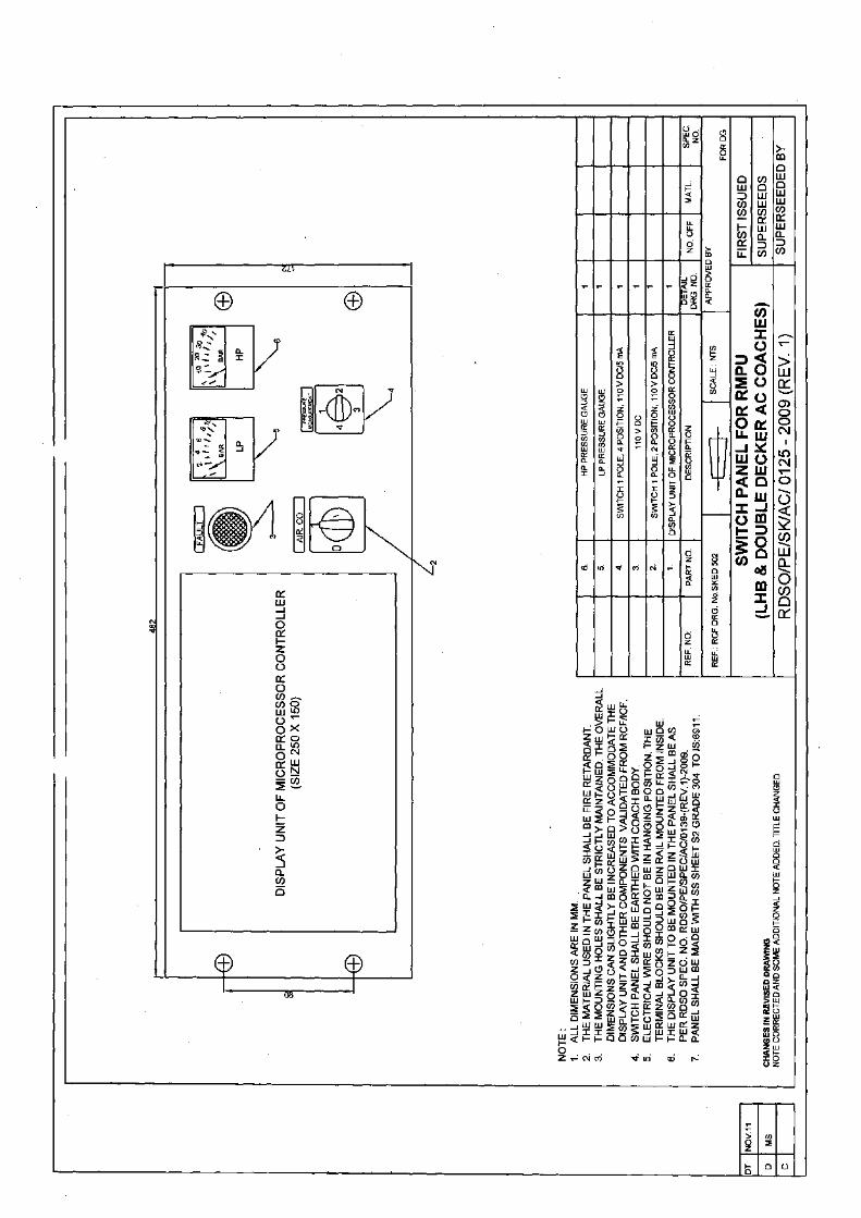
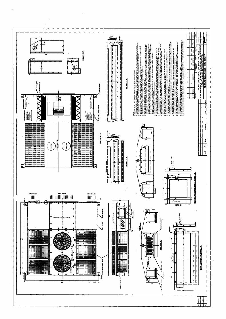
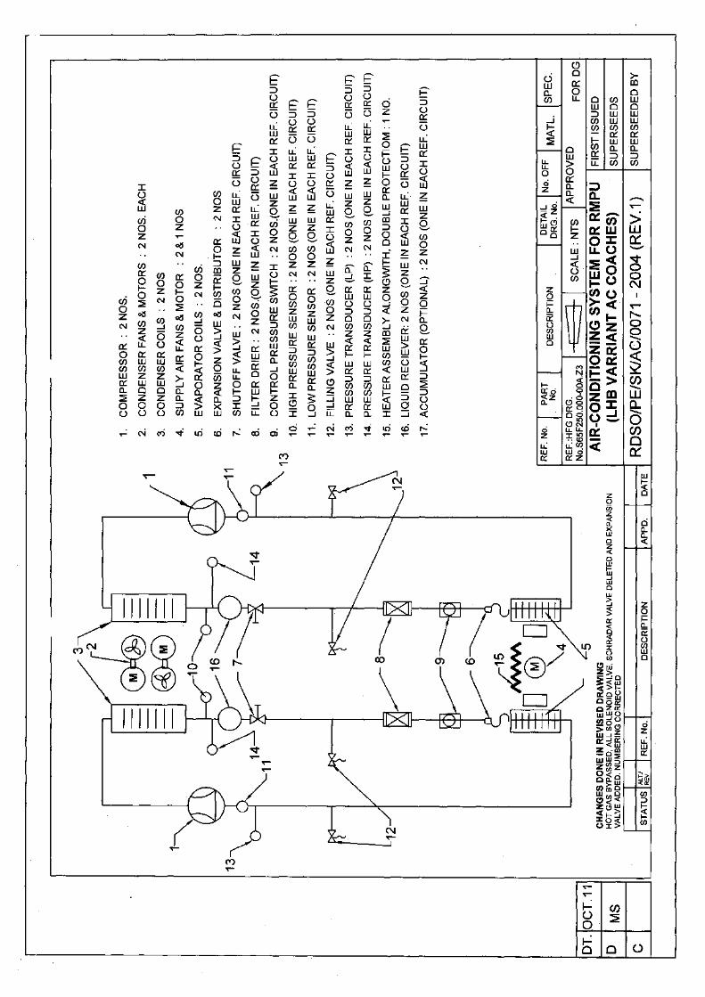
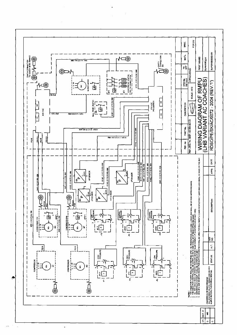
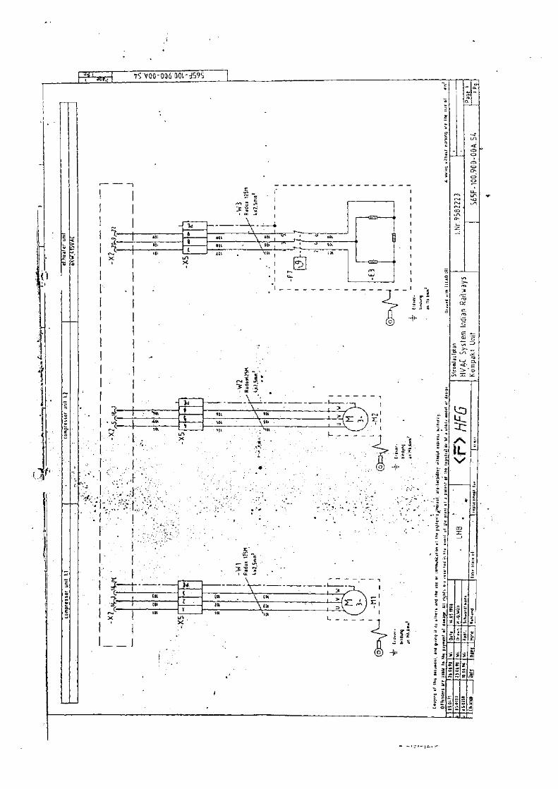
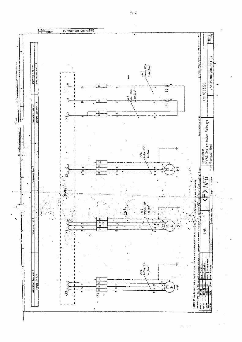
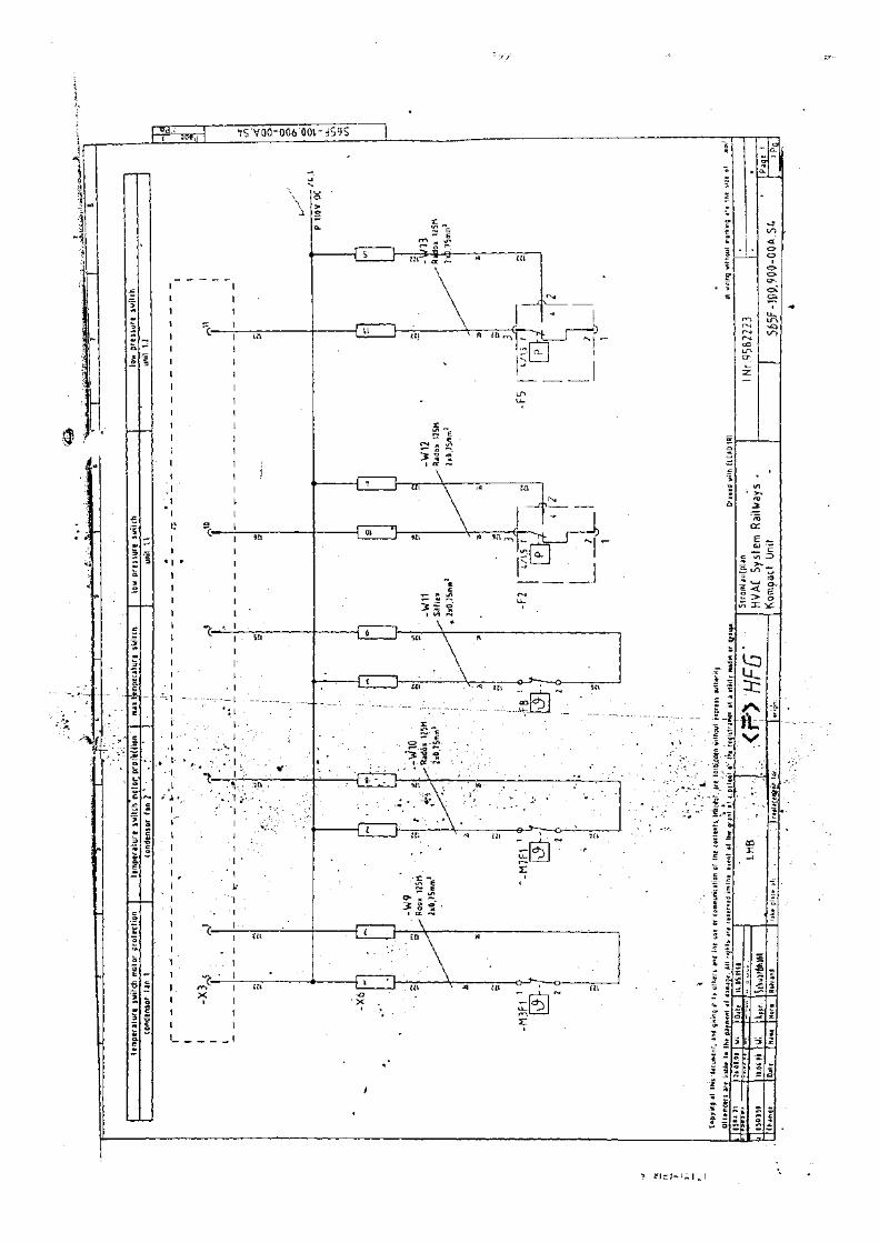
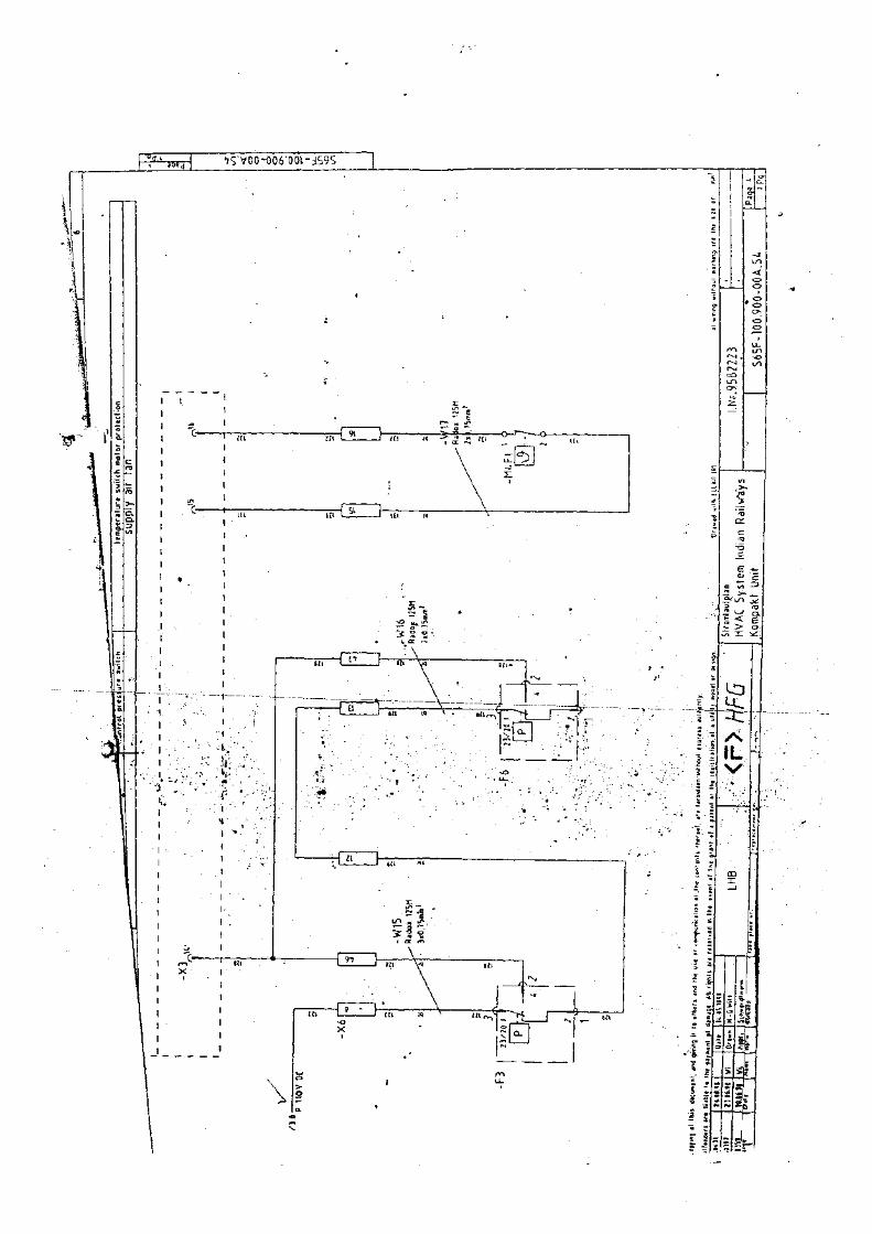
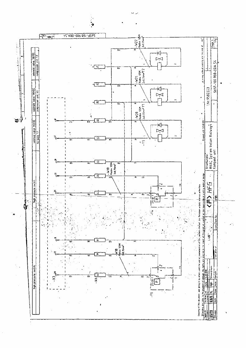
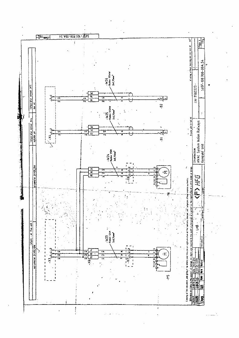
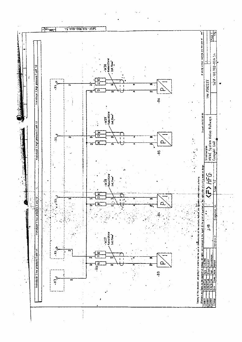
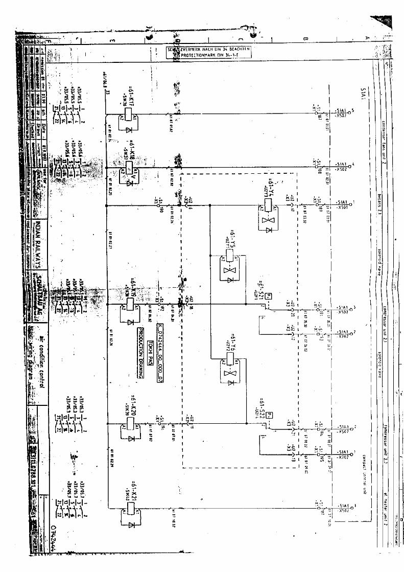
••• ~J. ••
, .".' ~l<.- •• ••• ••• ~' .--. .~ J
',.,~),~
"Co " """""1 "RK MACH DIN ,SC ,ZVERHE R DIN l~.'-[
t PROTHTIONHA K _
!';~~'4;-:_';
I.
~~~ : I
e I~. I
I.',1,II
""r.,~.·:t~ ..__·~:'-", • L)(l;i
,II
""-"• I
~"""N:l:o
" I 5~~~ 0- -X502CD ~
~~III
~~ 1~10::7'-;;:- _ X 50 1
~ §I~IIIII\
~\-'I
IIIII\
IIIII ~I 2-
~oii
I ~'"I
\\
IIII ~
ilI "IIIIII
n I!I~ I~ I~.
I~
" Iil~~ I0
" Ic?... ~•...
;.,-:-1"f" ,-,
11II1IIIIII
I , •I ~l;iI ~;;;,III
, r
, - - ----
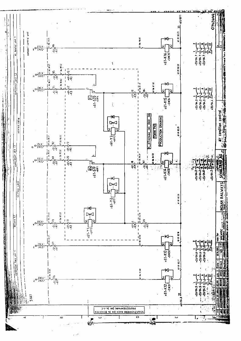
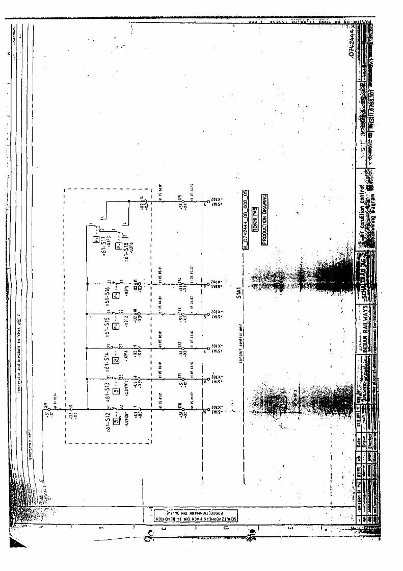
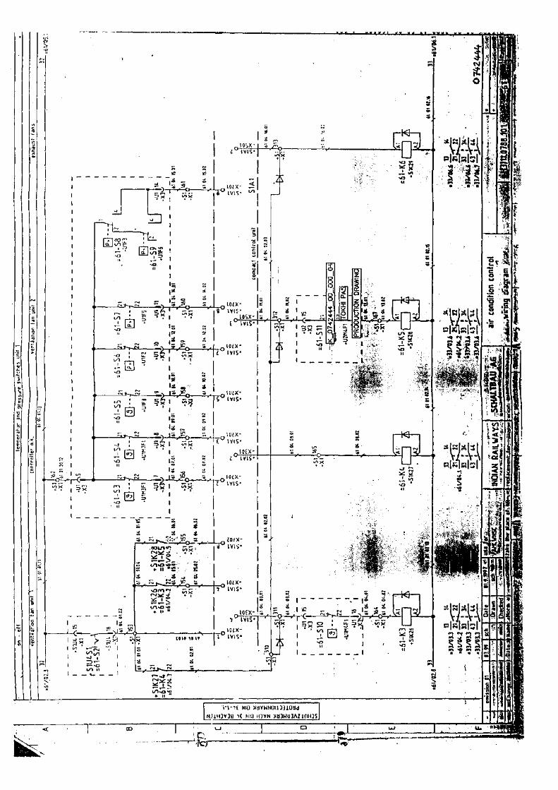
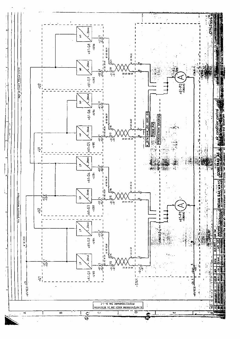
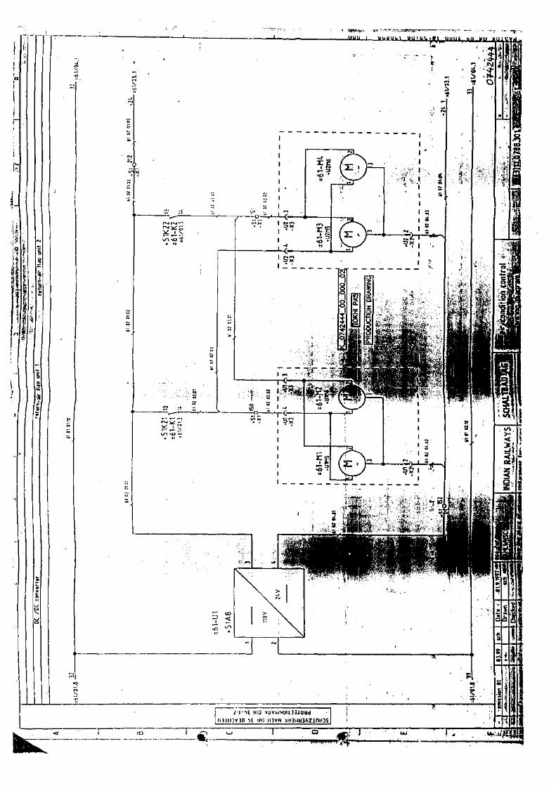
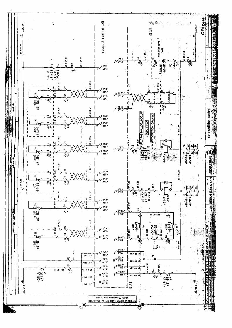
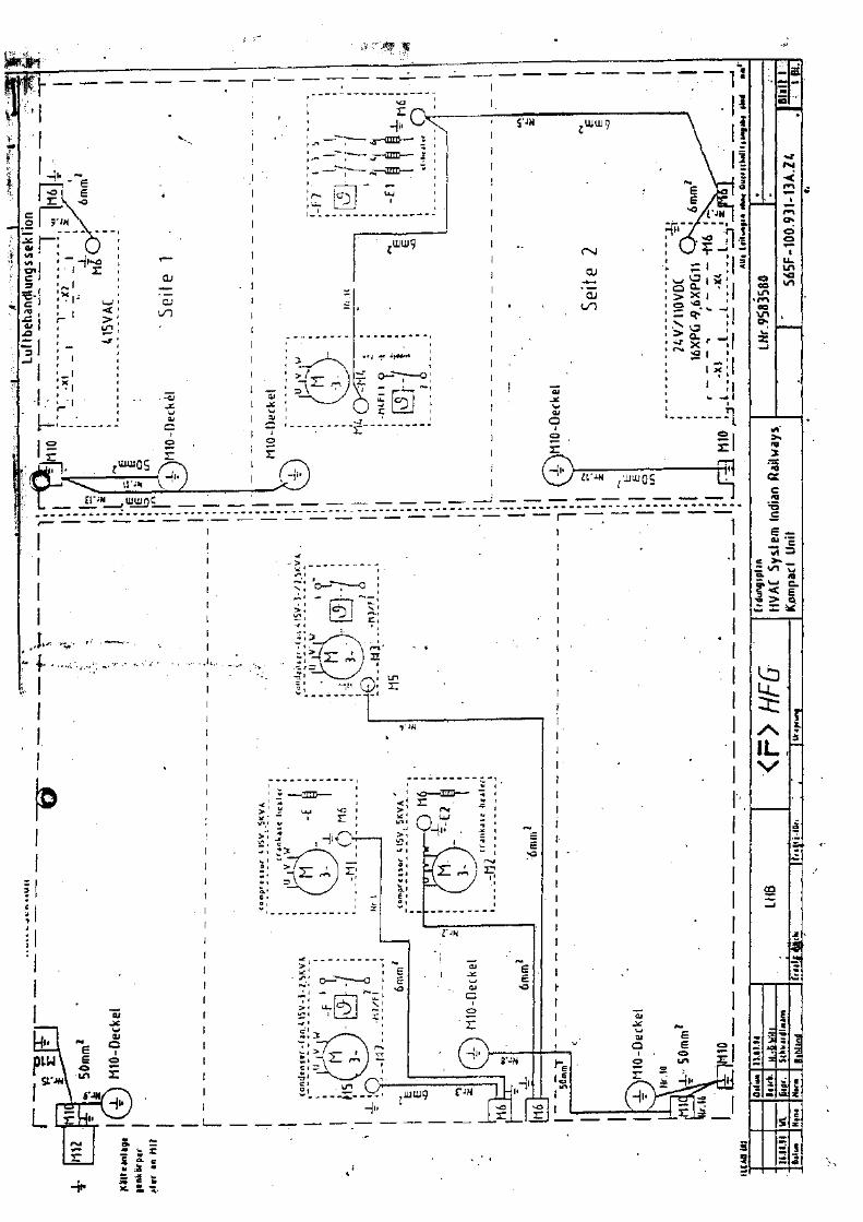

![Fuel Cell Sensor Based Breath Alcohol Analyzer [ HAND H ...€¦ · Fuel Cell Sensor Based Breath Alcohol Analyzer [ HAND H ELD TYPE ] Complied to RDSO SPEC NO: RDSO/2015/EL/SPEC/0119](https://img.pdfslide.us/doc/110x75/5f31d256bbf918721221e248/fuel-cell-sensor-based-breath-alcohol-analyzer-hand-h-fuel-cell-sensor-based.jpg)