Embed Size (px)
Citation preview
Page 1 of 20
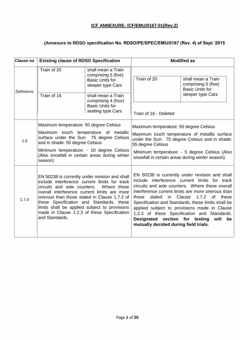
ICF ANNEXURE- ICF/EMU/0167-01(Rev.2)
(Annexure to RDSO specification No. RDSO/PE/SPEC/EMU/0167 (Rev. 4) of Sept.’2015
Clause no Existing clause of RDSO Specification Modified as
Definitons
Train of 20 shall mean a Train comprising 5 (five) Basic Units for sleeper type Cars
Train of 16 shall mean a Train comprising 4 (four) Basic Units for seating type Cars
Train of 16 - Deleted
Train of 20 shall mean a Train comprising 5 (five) Basic Units for sleeper type Cars
1.6
Maximum temperature: 50 degree Celsius
Maximum touch temperature of metallic surface under the Sun: 75 degree Celsius and in shade: 55 degree Celsius
Minimum temperature: - 10 degree Celsius (Also snowfall in certain areas during winter season)
Maximum temperature: 50 degree Celsius
Maximum touch temperature of metallic surface under the Sun: 75 degree Celsius and in shade: 55 degree Celsius
Minimum temperature: - 5 degree Celsius (Also
snowfall in certain areas during winter season)
1.7.4
EN 50238 is currently under revision and shall include interference current limits for track circuits and axle counters. Where these overall interference current limits are more onerous than those stated in Clause 1.7.2 of these Specification and Standards, these limits shall be applied subject to provisions made in Clause 1.2.3 of these Specification and Standards.
EN 50238 is currently under revision and shall
include interference current limits for track
circuits and axle counters. Where these overall
interference current limits are more onerous than
those stated in Clause 1.7.2 of these
Specification and Standards, these limits shall be
applied subject to provisions made in Clause
1.2.3 of these Specification and Standards.
Designated section for testing will be
mutually decided during field trials.
Page 2 of 20
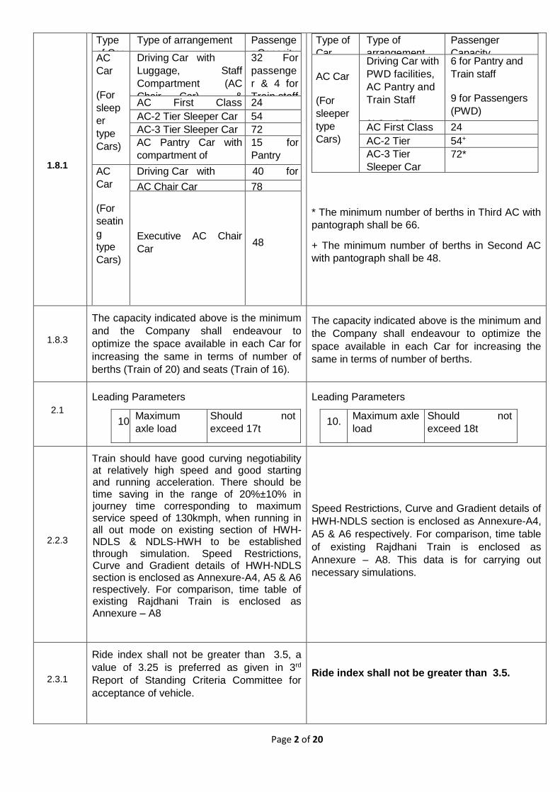
1.8.1
Type
of Car
Type of arrangement Passenge
r Capacity AC
Car
(For
sleep
er
type
Cars)
Driving Car with
Luggage, Staff
Compartment (AC
Chair Car) &
Passenger area (AC- 3
tier Sleeper )
32 For
passenge
r & 4 for
Train staff AC First Class
Sleeper Cars
24
AC-2 Tier Sleeper Car 54
AC-3 Tier Sleeper Car 72
AC Pantry Car with
compartment of
Pantry and Train staff
(AC-3 Tier Sleeper
compartment)
15 for
Pantry
and Train
staff AC
Car
(For
seatin
g
type
Cars)
Driving Car with
Luggage, Staff
Compartment (AC
Chair Car) &
Passenger area
(ACChair Car)
40 for
passenge
r & 4 for
Train staff
AC Chair Car 78
Executive AC Chair
Car 48
* The minimum number of berths in Third AC with
pantograph shall be 66.
+ The minimum number of berths in Second AC
with pantograph shall be 48.
Type of
Car
Type of
arrangement
Passenger
Capacity
AC Car
(For
sleeper
type
Cars)
Driving Car with
PWD facilities,
AC Pantry and
Train Staff
(AC - 3 Tier
Sleeper
Compartment)
6 for Pantry and
Train staff
9 for Passengers
(PWD)
AC First Class
Sleeper Cars
24
AC-2 Tier
Sleeper Car
54+
AC-3 Tier
Sleeper Car
72*
1.8.3
The capacity indicated above is the minimum
and the Company shall endeavour to
optimize the space available in each Car for
increasing the same in terms of number of
berths (Train of 20) and seats (Train of 16).
The capacity indicated above is the minimum and
the Company shall endeavour to optimize the
space available in each Car for increasing the
same in terms of number of berths.
2.1
Leading Parameters
10. Maximum
axle load
Should not
exceed 17t
Leading Parameters
10. Maximum axle
load
Should not
exceed 18t
2.2.3
Train should have good curving negotiability at relatively high speed and good starting and running acceleration. There should be time saving in the range of 20%±10% in journey time corresponding to maximum service speed of 130kmph, when running in all out mode on existing section of HWH-NDLS & NDLS-HWH to be established through simulation. Speed Restrictions, Curve and Gradient details of HWH-NDLS section is enclosed as Annexure-A4, A5 & A6 respectively. For comparison, time table of existing Rajdhani Train is enclosed as Annexure – A8
Speed Restrictions, Curve and Gradient details of
HWH-NDLS section is enclosed as Annexure-A4,
A5 & A6 respectively. For comparison, time table
of existing Rajdhani Train is enclosed as
Annexure – A8. This data is for carrying out
necessary simulations.
2.3.1
Ride index shall not be greater than 3.5, a
value of 3.25 is preferred as given in 3rd
Report of Standing Criteria Committee for
acceptance of vehicle.
Ride index shall not be greater than 3.5.
Page 3 of 20
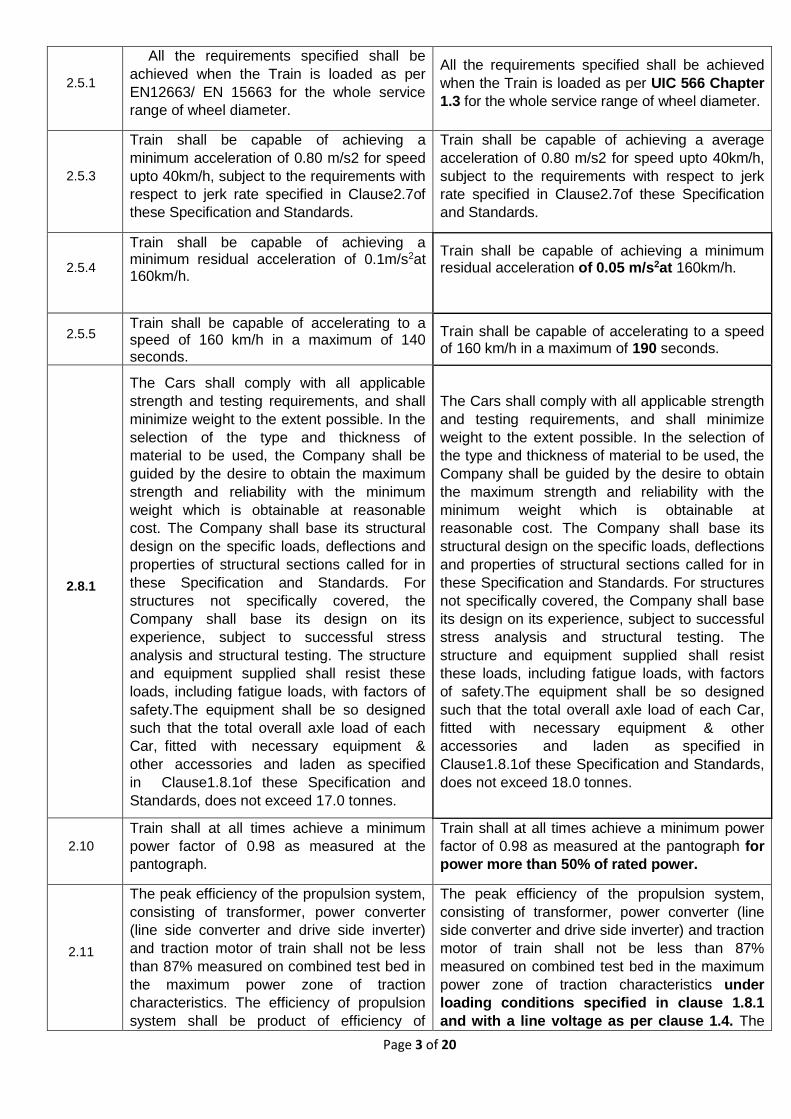
2.5.1
All the requirements specified shall be
achieved when the Train is loaded as per
EN12663/ EN 15663 for the whole service
range of wheel diameter.
All the requirements specified shall be achieved
when the Train is loaded as per UIC 566 Chapter
1.3 for the whole service range of wheel diameter.
2.5.3
Train shall be capable of achieving a
minimum acceleration of 0.80 m/s2 for speed
upto 40km/h, subject to the requirements with
respect to jerk rate specified in Clause2.7of
these Specification and Standards.
Train shall be capable of achieving a average
acceleration of 0.80 m/s2 for speed upto 40km/h,
subject to the requirements with respect to jerk
rate specified in Clause2.7of these Specification
and Standards.
2.5.4
Train shall be capable of achieving a minimum residual acceleration of 0.1m/s2at 160km/h.
Train shall be capable of achieving a minimum residual acceleration of 0.05 m/s2at 160km/h.
2.5.5 Train shall be capable of accelerating to a speed of 160 km/h in a maximum of 140 seconds.
Train shall be capable of accelerating to a speed of 160 km/h in a maximum of 190 seconds.
2.8.1
The Cars shall comply with all applicable
strength and testing requirements, and shall
minimize weight to the extent possible. In the
selection of the type and thickness of
material to be used, the Company shall be
guided by the desire to obtain the maximum
strength and reliability with the minimum
weight which is obtainable at reasonable
cost. The Company shall base its structural
design on the specific loads, deflections and
properties of structural sections called for in
these Specification and Standards. For
structures not specifically covered, the
Company shall base its design on its
experience, subject to successful stress
analysis and structural testing. The structure
and equipment supplied shall resist these
loads, including fatigue loads, with factors of
safety.The equipment shall be so designed
such that the total overall axle load of each
Car, fitted with necessary equipment &
other accessories and laden as specified
in Clause1.8.1of these Specification and
Standards, does not exceed 17.0 tonnes.
The Cars shall comply with all applicable strength
and testing requirements, and shall minimize
weight to the extent possible. In the selection of
the type and thickness of material to be used, the
Company shall be guided by the desire to obtain
the maximum strength and reliability with the
minimum weight which is obtainable at
reasonable cost. The Company shall base its
structural design on the specific loads, deflections
and properties of structural sections called for in
these Specification and Standards. For structures
not specifically covered, the Company shall base
its design on its experience, subject to successful
stress analysis and structural testing. The
structure and equipment supplied shall resist
these loads, including fatigue loads, with factors
of safety.The equipment shall be so designed
such that the total overall axle load of each Car,
fitted with necessary equipment & other
accessories and laden as specified in
Clause1.8.1of these Specification and Standards,
does not exceed 18.0 tonnes.
2.10
Train shall at all times achieve a minimum
power factor of 0.98 as measured at the
pantograph.
Train shall at all times achieve a minimum power
factor of 0.98 as measured at the pantograph for
power more than 50% of rated power.
2.11
The peak efficiency of the propulsion system,
consisting of transformer, power converter
(line side converter and drive side inverter)
and traction motor of train shall not be less
than 87% measured on combined test bed in
the maximum power zone of traction
characteristics. The efficiency of propulsion
system shall be product of efficiency of
The peak efficiency of the propulsion system,
consisting of transformer, power converter (line
side converter and drive side inverter) and traction
motor of train shall not be less than 87%
measured on combined test bed in the maximum
power zone of traction characteristics under
loading conditions specified in clause 1.8.1
and with a line voltage as per clause 1.4. The
Page 4 of 20
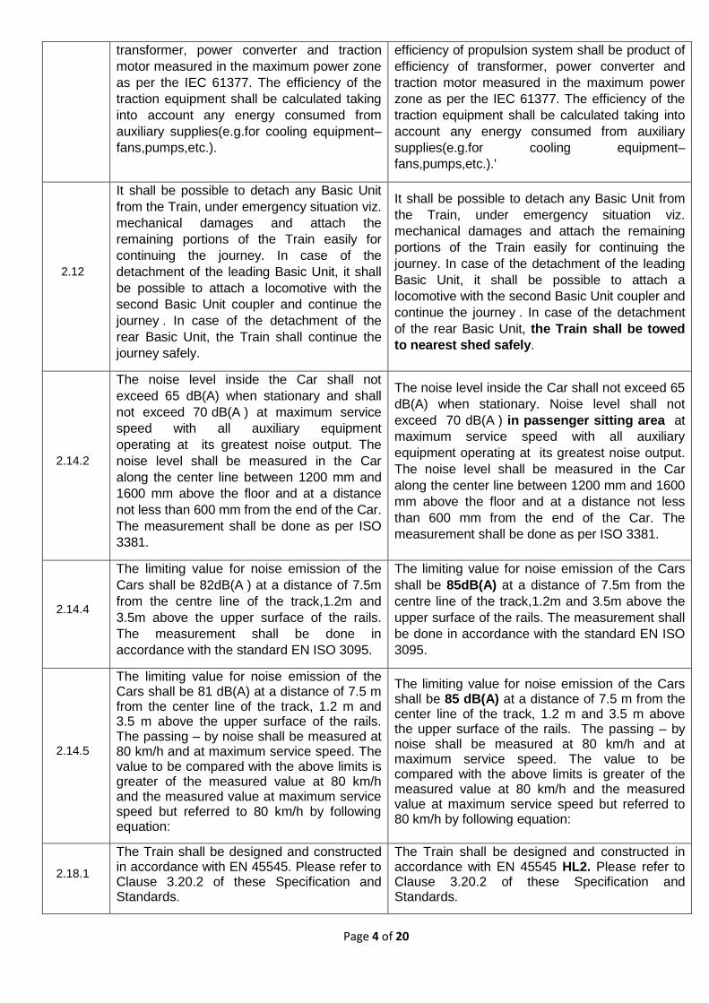
transformer, power converter and traction
motor measured in the maximum power zone
as per the IEC 61377. The efficiency of the
traction equipment shall be calculated taking
into account any energy consumed from
auxiliary supplies(e.g.for cooling equipment–
fans,pumps,etc.).
efficiency of propulsion system shall be product of
efficiency of transformer, power converter and
traction motor measured in the maximum power
zone as per the IEC 61377. The efficiency of the
traction equipment shall be calculated taking into
account any energy consumed from auxiliary
supplies(e.g.for cooling equipment–
fans,pumps,etc.).'
2.12
It shall be possible to detach any Basic Unit
from the Train, under emergency situation viz.
mechanical damages and attach the
remaining portions of the Train easily for
continuing the journey. In case of the
detachment of the leading Basic Unit, it shall
be possible to attach a locomotive with the
second Basic Unit coupler and continue the
journey . In case of the detachment of the
rear Basic Unit, the Train shall continue the
journey safely.
It shall be possible to detach any Basic Unit from
the Train, under emergency situation viz.
mechanical damages and attach the remaining
portions of the Train easily for continuing the
journey. In case of the detachment of the leading
Basic Unit, it shall be possible to attach a
locomotive with the second Basic Unit coupler and
continue the journey . In case of the detachment
of the rear Basic Unit, the Train shall be towed
to nearest shed safely.
2.14.2
The noise level inside the Car shall not
exceed 65 dB(A) when stationary and shall
not exceed 70 dB(A ) at maximum service
speed with all auxiliary equipment
operating at its greatest noise output. The
noise level shall be measured in the Car
along the center line between 1200 mm and
1600 mm above the floor and at a distance
not less than 600 mm from the end of the Car.
The measurement shall be done as per ISO
3381.
The noise level inside the Car shall not exceed 65
dB(A) when stationary. Noise level shall not
exceed 70 dB(A ) in passenger sitting area at
maximum service speed with all auxiliary
equipment operating at its greatest noise output.
The noise level shall be measured in the Car
along the center line between 1200 mm and 1600
mm above the floor and at a distance not less
than 600 mm from the end of the Car. The
measurement shall be done as per ISO 3381.
2.14.4
The limiting value for noise emission of the
Cars shall be 82dB(A ) at a distance of 7.5m
from the centre line of the track,1.2m and
3.5m above the upper surface of the rails.
The measurement shall be done in
accordance with the standard EN ISO 3095.
The limiting value for noise emission of the Cars
shall be 85dB(A) at a distance of 7.5m from the
centre line of the track,1.2m and 3.5m above the
upper surface of the rails. The measurement shall
be done in accordance with the standard EN ISO
3095.
2.14.5
The limiting value for noise emission of the Cars shall be 81 dB(A) at a distance of 7.5 m from the center line of the track, 1.2 m and 3.5 m above the upper surface of the rails. The passing – by noise shall be measured at 80 km/h and at maximum service speed. The value to be compared with the above limits is greater of the measured value at 80 km/h and the measured value at maximum service speed but referred to 80 km/h by following equation:
The limiting value for noise emission of the Cars shall be 85 dB(A) at a distance of 7.5 m from the center line of the track, 1.2 m and 3.5 m above the upper surface of the rails. The passing – by noise shall be measured at 80 km/h and at maximum service speed. The value to be compared with the above limits is greater of the measured value at 80 km/h and the measured value at maximum service speed but referred to 80 km/h by following equation:
2.18.1
The Train shall be designed and constructed in accordance with EN 45545. Please refer to Clause 3.20.2 of these Specification and Standards.
The Train shall be designed and constructed in accordance with EN 45545 HL2. Please refer to Clause 3.20.2 of these Specification and Standards.
Page 5 of 20
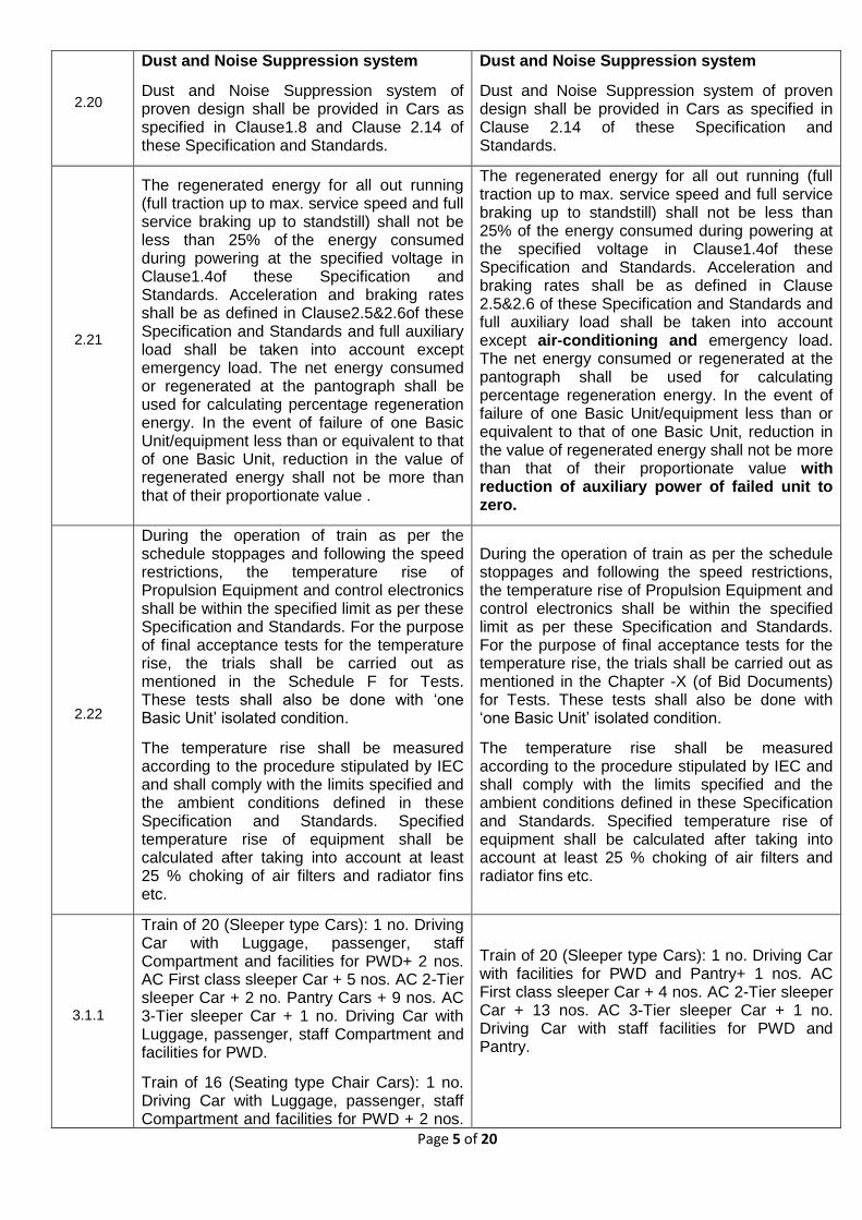
2.20
Dust and Noise Suppression system
Dust and Noise Suppression system of proven design shall be provided in Cars as specified in Clause1.8 and Clause 2.14 of these Specification and Standards.
Dust and Noise Suppression system
Dust and Noise Suppression system of proven design shall be provided in Cars as specified in Clause 2.14 of these Specification and Standards.
2.21
The regenerated energy for all out running (full traction up to max. service speed and full service braking up to standstill) shall not be less than 25% of the energy consumed during powering at the specified voltage in Clause1.4of these Specification and Standards. Acceleration and braking rates shall be as defined in Clause2.5&2.6of these Specification and Standards and full auxiliary load shall be taken into account except emergency load. The net energy consumed or regenerated at the pantograph shall be used for calculating percentage regeneration energy. In the event of failure of one Basic Unit/equipment less than or equivalent to that of one Basic Unit, reduction in the value of regenerated energy shall not be more than that of their proportionate value .
The regenerated energy for all out running (full traction up to max. service speed and full service braking up to standstill) shall not be less than 25% of the energy consumed during powering at the specified voltage in Clause1.4of these Specification and Standards. Acceleration and braking rates shall be as defined in Clause 2.5&2.6 of these Specification and Standards and full auxiliary load shall be taken into account except air-conditioning and emergency load. The net energy consumed or regenerated at the pantograph shall be used for calculating percentage regeneration energy. In the event of failure of one Basic Unit/equipment less than or equivalent to that of one Basic Unit, reduction in the value of regenerated energy shall not be more than that of their proportionate value with reduction of auxiliary power of failed unit to zero.
2.22
During the operation of train as per the schedule stoppages and following the speed restrictions, the temperature rise of Propulsion Equipment and control electronics shall be within the specified limit as per these Specification and Standards. For the purpose of final acceptance tests for the temperature rise, the trials shall be carried out as mentioned in the Schedule F for Tests. These tests shall also be done with ‘one Basic Unit’ isolated condition.
The temperature rise shall be measured according to the procedure stipulated by IEC and shall comply with the limits specified and the ambient conditions defined in these Specification and Standards. Specified temperature rise of equipment shall be calculated after taking into account at least 25 % choking of air filters and radiator fins etc.
During the operation of train as per the schedule stoppages and following the speed restrictions, the temperature rise of Propulsion Equipment and control electronics shall be within the specified limit as per these Specification and Standards. For the purpose of final acceptance tests for the temperature rise, the trials shall be carried out as mentioned in the Chapter -X (of Bid Documents) for Tests. These tests shall also be done with ‘one Basic Unit’ isolated condition.
The temperature rise shall be measured according to the procedure stipulated by IEC and shall comply with the limits specified and the ambient conditions defined in these Specification and Standards. Specified temperature rise of equipment shall be calculated after taking into account at least 25 % choking of air filters and radiator fins etc.
3.1.1
Train of 20 (Sleeper type Cars): 1 no. Driving Car with Luggage, passenger, staff Compartment and facilities for PWD+ 2 nos. AC First class sleeper Car + 5 nos. AC 2-Tier sleeper Car + 2 no. Pantry Cars + 9 nos. AC 3-Tier sleeper Car + 1 no. Driving Car with Luggage, passenger, staff Compartment and facilities for PWD.
Train of 16 (Seating type Chair Cars): 1 no. Driving Car with Luggage, passenger, staff Compartment and facilities for PWD + 2 nos.
Train of 20 (Sleeper type Cars): 1 no. Driving Car with facilities for PWD and Pantry+ 1 nos. AC First class sleeper Car + 4 nos. AC 2-Tier sleeper Car + 13 nos. AC 3-Tier sleeper Car + 1 no. Driving Car with staff facilities for PWD and Pantry.

Page 6 of 20
AC First class (executive) Chair Car +12 nos. AC Chair Car + 1 no. Driving Car with Luggage, passenger, staff Compartment and facilities for PWD.
3.1.8
The Train shall be provided with a speed
control system, which shall enable the Driver
to preset the speed at which the Train is
desired to run irrespective of the track profile.
The speed control shall work within the limits
of maximum electrical performance as
specified in Chapter 2 of these Specification
and Standards. The selection of speed shall
be possible by press of a switch. However,
the system shall be inherently fail safe and
shall immediately come out of the pre-set
speed mode to normal mode on actuation of
master cum brake controller or as required
from safety considerations.
The Train shall be provided with a speed control
system, which shall enable the Driver to preset
the speed at which the Train is desired to run
irrespective of the track profile. The speed control
shall work within the limits of maximum electrical
performance as specified in Chapter 2 of these
Specification and Standards. The selection of
speed shall be possible by press of a switch.
However, the system shall be inherently fail safe
and shall immediately come out of the pre-set
speed mode to normal mode on actuation of
master cum brake controller in traction/
coasting/ braking or as required from safety
considerations.
3.1.12
Air duct design and filter arrangement shall
be such so as to prevent ingress of water
from these locations. The system shall be
designed in such a way that the intervals
between cleaning of any filter elements shall
not be less than two months. The design
shall allow in-situ cleaning of filters with the
required maintenance tools.
Air duct design and filter arrangement shall be
such so as to prevent ingress of water from these
locations. The system shall be designed in such
a way that the intervals between cleaning of any
filter elements shall not be less than 45 days.
The design shall allow in-situ cleaning of filters
with the required maintenance tools.
3.1.15
As much equipment as possible (including
traction equipment) shall be mounted either
on the under frame or roof so as to maximize
the space available to accommodate
passengers. Where equipment is located
inside the Car body, it shall be located
behind paneling and shall not reduce the
space available to accommodate
passengers. No equipment rooms or cubicles
are permitted within the Car body .
As much equipment as possible (including
traction equipment) shall be mounted either on
the under frame or roof so as to maximize the
space available to accommodate passengers.
Where equipment is located inside the Car body,
it shall be located behind panelling and shall
not reduce the space available to accommodate
passengers. No equipment rooms or cubicles are
permitted within the Car body, except at the end
walls.
3.2
The Train shall be connected at 25 kV level,
through a 25 kV HT coupler so that in the
event of failure of one HT equipment
including pantograph, main circuit breaker
and HT coupler, the whole Train can still be
powered .
The Train shall be connected at 25 kV level,
through a 25 kV HT coupler so that in the event of
failure of one HT equipment including earthing of
pantograph, main circuit breaker and HT coupler,
the whole Train can still be powered up except
affected basic unit .
3.2 .1
3.2.1 Each End Basic Unit shall have one
Pantograph Car having two pantographs. In
normal condition, Train shall work on two
Pantographs i.e. one of each Pantograph
Cars. The pantograph selector switch shall
be provided in the Driver’s cab for raising and
lowering of any of the pantographs. The
raising or lowering of the pantograph, with
the Train in motion, shall not cause any
3.2.1 Each Basic Unit shall have one
Pantograph Car having one pantograph. In
normal condition, Train shall work on two
Pantographs i.e. one of each Pantograph Car of
end basic units. The pantograph selector switch
shall be provided in the Driver’s cab for raising
and lowering of any of the pantographs. The
raising or lowering of the pantograph, with the
Train in motion, shall not cause any unwanted

Page 7 of 20
unwanted disturbance to OHE. In the event
of failure/damage of both pantographs of a
Pantograph Car, it shall still be possible to
work the Train with single Pantograph of the
remaining Pantograph Car.
disturbance to OHE. In the event of
failure/damage of single/both pantograph(s), it
shall be possible to raise the pantograph(s) of
other pantograph car(s), by opening/closing of
isolators mounted on the roof. The HT cable (25
KV) from the pantograph shall be extended to
motor cars through flexible jumpers in
between the cars.
3.3
Each pantograph car shall be provided with a
minimum of one circuit breaker.Other cars
having traction transformer shall also be
provided with main circuit breaker.
Each pantograph car/transformer car shall be
provided with a minimum of one circuit breaker.
The AC earthing switch provided shall be
compatible with circuit breaker.
3.4
Two metal oxide gapless lightning arrestors
shall be provided on the roof of each Car
fitted with a pantograph and/or traction
transformer for protection against the line
voltage transients caused by lightning and
system switching. One lightning arrestor shall
be connected to the high voltage circuit
between the pantograph & the main circuit
breaker and the other shall be connected to
the high voltage circuit between the main
circuit breaker and the transformer. Other
Cars fitted with main transformer shall also
be provided with gapless lighting arresters on
roof in between circuit breaker and main
transformer. These gapless lighting arrestors
shall have minimum line discharge class-3 .
'Two metal oxide gapless lightning arrestors shall
be provided on the roof of each Car fitted with a
pantograph and/or traction transformer for
protection against the line voltage transients
caused by lightning and system switching. One
lightning arrestor shall be connected to the high
voltage circuit between the pantograph & the
main circuit breaker and the other shall be
connected to the high voltage circuit between the
main circuit breaker and the transformer. Other
Cars fitted with main transformer shall also be
provided with gapless lighting arresters on roof in
between circuit breaker and main transformer.
These gapless lighting arrestors shall have
minimum line discharge class-2 & 3 both.
3.7.2
The wheel slip detection and correction
system shall be an integral part of the control
system of the power converters/inverter
which shall capture any excessive
acceleration, differential speeds between
axles, over speed and any other parameter
considered necessary to maximize adhesion
and minimize wheel slipping / skidding.
The wheel slip detection and correction system
shall be an integral part of the control system of
the power converters/inverter which shall
maximize adhesion and minimize wheel slipping /
skidding.
3.7.8
The protection scheme of the traction system shall ensure that: • A single earth fault does not have any
adverse impact on the performance of the traction system.
• In the case of multiple earth faults or phase to phase faults, the affected equipment shall be immediately shut down and no damage to the equipment shall occur.
The protection scheme of the traction system
shall ensure that in the case of any earth fault or
phase to phase faults, the respective traction
converter should immediately shut down to
prevent damage to any equipment.
3.8.6 Because of track irregularities, level of
shocks and vibrations to which traction
motors are exposed are far more than
actually given in IEC 61373. It is
recommended that the Company must carry
out instrumented trials on existing stock for
measurement of shocks and vibrations on
It should be noted that because of track
irregularities, level of shocks and vibrations to
which traction motors are exposed are
generally more than actually given in IEC
61373.
Page 8 of 20
Government’s tracks, at design stage.
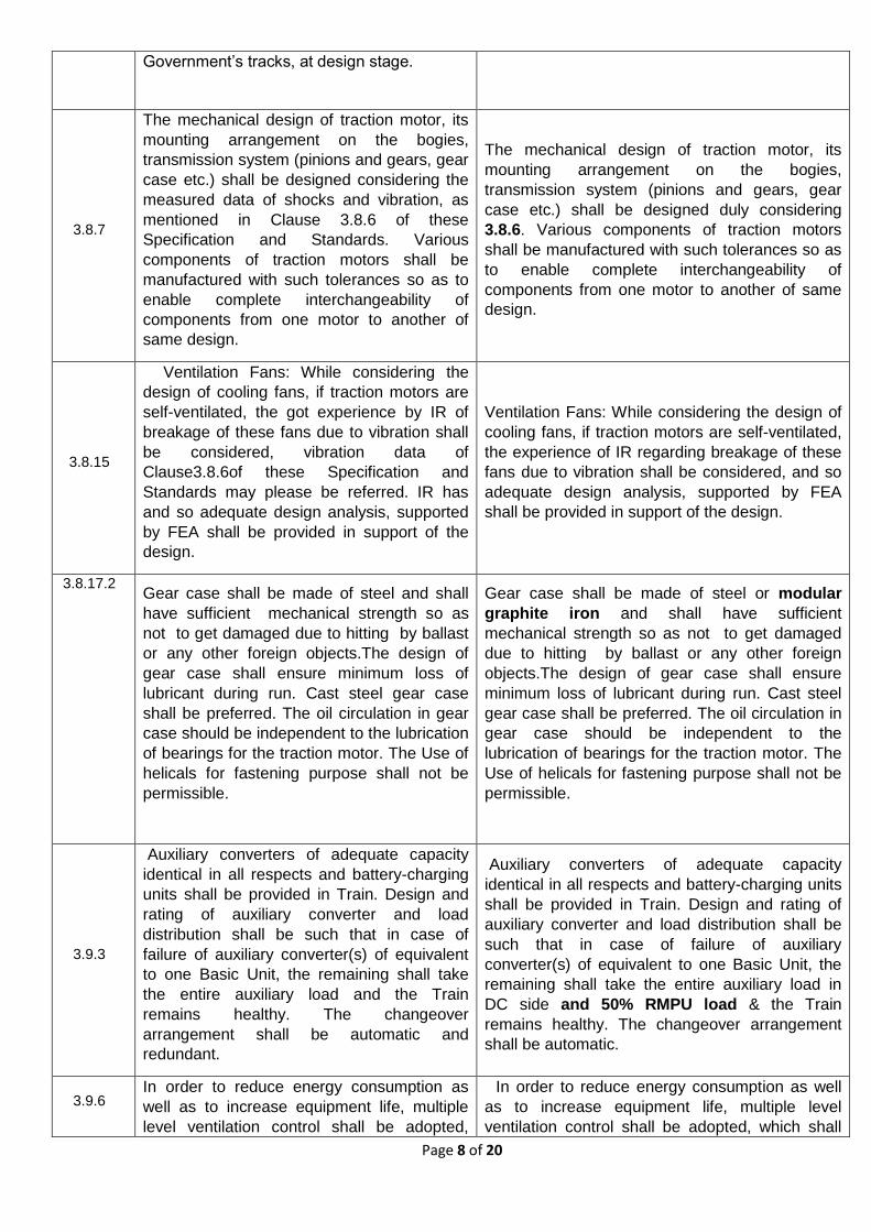
3.8.7
The mechanical design of traction motor, its
mounting arrangement on the bogies,
transmission system (pinions and gears, gear
case etc.) shall be designed considering the
measured data of shocks and vibration, as
mentioned in Clause 3.8.6 of these
Specification and Standards. Various
components of traction motors shall be
manufactured with such tolerances so as to
enable complete interchangeability of
components from one motor to another of
same design.
The mechanical design of traction motor, its
mounting arrangement on the bogies,
transmission system (pinions and gears, gear
case etc.) shall be designed duly considering
3.8.6. Various components of traction motors
shall be manufactured with such tolerances so as
to enable complete interchangeability of
components from one motor to another of same
design.
3.8.15
Ventilation Fans: While considering the
design of cooling fans, if traction motors are
self-ventilated, the got experience by IR of
breakage of these fans due to vibration shall
be considered, vibration data of
Clause3.8.6of these Specification and
Standards may please be referred. IR has
and so adequate design analysis, supported
by FEA shall be provided in support of the
design.
Ventilation Fans: While considering the design of
cooling fans, if traction motors are self-ventilated,
the experience of IR regarding breakage of these
fans due to vibration shall be considered, and so
adequate design analysis, supported by FEA
shall be provided in support of the design.
3.8.17.2 Gear case shall be made of steel and shall
have sufficient mechanical strength so as
not to get damaged due to hitting by ballast
or any other foreign objects.The design of
gear case shall ensure minimum loss of
lubricant during run. Cast steel gear case
shall be preferred. The oil circulation in gear
case should be independent to the lubrication
of bearings for the traction motor. The Use of
helicals for fastening purpose shall not be
permissible.
Gear case shall be made of steel or modular
graphite iron and shall have sufficient
mechanical strength so as not to get damaged
due to hitting by ballast or any other foreign
objects.The design of gear case shall ensure
minimum loss of lubricant during run. Cast steel
gear case shall be preferred. The oil circulation in
gear case should be independent to the
lubrication of bearings for the traction motor. The
Use of helicals for fastening purpose shall not be
permissible.
3.9.3
Auxiliary converters of adequate capacity
identical in all respects and battery-charging
units shall be provided in Train. Design and
rating of auxiliary converter and load
distribution shall be such that in case of
failure of auxiliary converter(s) of equivalent
to one Basic Unit, the remaining shall take
the entire auxiliary load and the Train
remains healthy. The changeover
arrangement shall be automatic and
redundant.
Auxiliary converters of adequate capacity
identical in all respects and battery-charging units
shall be provided in Train. Design and rating of
auxiliary converter and load distribution shall be
such that in case of failure of auxiliary
converter(s) of equivalent to one Basic Unit, the
remaining shall take the entire auxiliary load in
DC side and 50% RMPU load & the Train
remains healthy. The changeover arrangement
shall be automatic.
3.9.6 In order to reduce energy consumption as
well as to increase equipment life, multiple
level ventilation control shall be adopted,
In order to reduce energy consumption as well
as to increase equipment life, multiple level
ventilation control shall be adopted, which shall
Page 9 of 20
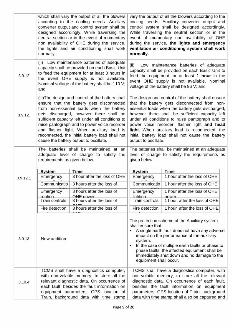
which shall vary the output of all the blowers
according to the cooling needs. Auxiliary
converter output and control system shall be
designed accordingly. While traversing the
neutral section or in the event of momentary
non availability of OHE during the service,
the lights and air conditioning shall work
normally.
vary the output of all the blowers according to the
cooling needs. Auxiliary converter output and
control system shall be designed accordingly.
While traversing the neutral section or in the
event of momentary non availability of OHE
during the service, the lights and emergency
ventilation air conditioning system shall work
normally.
3.9.12
(ii) Low maintenance batteries of adequate
capacity shall be provided on each Basic Unit
to feed the equipment for at least 3 hours in
the event OHE supply is not available.
Nominal voltage of the battery shall be 110 V;
and
(ii) Low maintenance batteries of adequate
capacity shall be provided on each Basic Unit to
feed the equipment for at least 1 hour in the
event OHE supply is not available. Nominal
voltage of the battery shall be 96 V; and
3.9.12.
(iii)The design and control of the battery shall
ensure that the battery gets disconnected
from non-essential loads when the battery
gets discharged, however there shall be
sufficient capacity left under all conditions to
raise pantograph and to power voice recorder
and flasher light. When auxiliary load is
reconnected, the initial battery load shall not
cause the battery output to oscillate.
The design and control of the battery shall ensure
that the battery gets disconnected from non-
essential loads when the battery gets discharged,
however there shall be sufficient capacity left
under all conditions to raise pantograph and to
power voice recorder, flasher light and head
light. When auxiliary load is reconnected, the
initial battery load shall not cause the battery
output to oscillate.
3.9.12.1
The batteries shall be maintained at an
adequate level of charge to satisfy the
requirements as given below:
System
maintained
Time Emergency
ventilation in
all Cars
including
Driving Cabs
3 hour after the loss of OHE
power Communicatio
n system (PIS
and PA
system)
3 hours after the loss of
OHE power Emergency
lighting
3 hours after the loss of
OHE power Train controls 3 hours after the loss of
OHE power Fire detection
system
3 hours after the loss of
OHE power
The batteries shall be maintained at an adequate
level of charge to satisfy the requirements as
given below:
System
maintained
Time Emergency
ventilation in
all Cars
including
Driving Cabs
1 hour after the loss of OHE
power Communicatio
n system (PIS
and PA
system)
1 hour after the loss of OHE
power Emergency
lighting
1 hour after the loss of OHE
power Train controls 1 hour after the loss of OHE
power Fire detection
system
1 hour after the loss of OHE
power
3.9.13 New addition
The protection scheme of the Auxiliary system shall ensure that: • A single earth fault does not have any adverse
impact on the performance of the auxiliary system.
• In the case of multiple earth faults or phase to phase faults, the affected equipment shall be immediately shut down and no damage to the equipment shall occur.
3.10.4
TCMS shall have a diagnostics computer,
with non-volatile memory, to store all the
relevant diagnostic data. On occurrence of
each fault, besides the fault information on
equipment parameters, GPS location of
Train, background data with time stamp
TCMS shall have a diagnostics computer, with
non-volatile memory, to store all the relevant
diagnostic data. On occurrence of each fault,
besides the fault information on equipment
parameters, GPS location of Train, background
data with time stamp shall also be captured and
Page 10 of 20
shall also be captured and stored with a
view to enable proper fault analysis. There
shall be a facility to capture post trigger and
pre-trigger background information. The
fault display to Driver shall also accompany
the standard trouble shooting instructions in
simple language. The diagnostic computer
shall specify diagnostic of fault up to card
level. Faults shall be suitably prioritized and
filtered so that the Driver and maintenance
staff receive information appropriate to their
roles. The diagnostic system shall be able
to identify and log the faults of the Train on
account of wrong operation by the Driver
and such data (including energy data) shall
be stored in the diagnostic computer for a
period of not less than 45 days. Application
software shall be provided to facilitate the
fault diagnosis and the analysis of
equipment wise failures. The steps required
for investigation to be done, shall be
displayed in simple language along with
background information. Such software
shall be compatible for working on
commercially available operating systems.
stored with a view to enable proper fault
analysis. There shall be a facility to capture
post trigger and pre-trigger background
information. The fault display to Driver shall
also accompany the standard trouble shooting
instructions in simple language. The diagnostic
computer shall specify diagnostic of fault up to
card level. Faults shall be suitably prioritized
and filtered so that the Driver and maintenance
staff receive information appropriate to their
roles. The diagnostic system shall be able to
identify and log the faults of the Train on
account of wrong operation by the Driver and
such data (including energy data) shall be
stored in the diagnostic computer for a period of
not less than 60 days. Application software
shall be provided to facilitate the fault diagnosis
and the analysis of equipment wise failures.
The steps required for investigation to be done,
shall be displayed in simple language along
with background information. Such software
shall be compatible for working on commercially
available operating systems.
3.10.5
A hand held, off line, electronic device shall
be provided for trouble shooting / rectification
of a fault by the crew. The device shall be
portable and easy to carry with feature of
pictorial identification of respective equipment
of the Train.
Deleted
3.10.6
The Train shall be provided with remote
diagnostic and tracking equipment. The
equipment shall be based on GPS and
GSM/GSM-R technologies. This equipment
shall perform the function of tracking of the
Train and also communicate with the Train
diagnostic system, and pass on this
information to the central server. The central
server shall be provided by the Company at
the Maintenance Depot(s). It shall be
possible to remotely send and obtain the
information stored in the diagnostic memory
of the computer system, depending on
availability of communication channel, for
control and diagnosis, with the aim of
facilitating and speeding up the maintenance
process of the Train. Exception reports shall
be generated by the TCMS and downloaded
remotely in the Maintenance Depot for
The Train shall be provided with remote
diagnostic and tracking equipment. The
equipment shall be based on GPS and
GSM/GSM-R technologies. This equipment shall
perform the function of tracking of the Train and
also communicate with the Train diagnostic
system, and pass on this information to the
central server. GSM SIM Card will be provided
by IR, the cost of which will be borne by IR.
Access to central server shall be provided for
data download and analysis, the cost of
which shall be borne by IR. It shall be possible
to remotely send and obtain the information
stored in the diagnostic memory of the computer
system, depending on availability of
communication channel, for control and
diagnosis, with the aim of facilitating and
speeding up the maintenance process of the
Train. Exception reports shall be generated by
the TCMS and downloaded remotely in the
Page 11 of 20
planning the corrective action. Maintenance Depot for planning the corrective
action.
3.10.16
For control functions integrated into the
TCMS, the requirements of EN 50126 and
EN 50128 shall be applied. In particular the
risks associated with the integration of
any control function shall be assessed and
the design of the TCMS (e.g. the SIL
according to EN 50128) shall reflect the level
of risk identified. Company has to submit the
safety analysis duly audited by the
independent certified agency. TCMS system
shall provide for real time distributed control
and modular processing of Sub-systems in a
redundant manner with high reliability and
availability. The Train control bus and the
Train controller shall be redundant.
Deleted
3.10.18
3.10.1Control and communication shall be based
on open control architecture and compliant
toIEC-61375 “TrainCommunication Network”
protocol or any other equivalent,
internationally published protocol. The
programmable devices should be
programmed using language compliant to
IEC-61131.
Control and communication shall be based
on open control architecture and compliant to
IEC-61375 “Train Communication Network”
protocol or any other equivalent, internationally
published protocol.
3.10.25
In case of rear Basic Unit removal, it shall be possible to operate the Train from leading Driving Car without loss of Train performance and functionality.
In ase.I In case of rear Basic Unit removal, it shall be
possible to operate the Train from leading Driving
Car without loss of Train performance and
functionality if Train communication network is
functioning.
3.10.26
In the event of removal of any Basic Unit from the Train, the TCMS shall configure the remaining Basic Units of the Train. In case of intermediate Basic Unit removal, the Train functionality and performance shall not deteriorate. In case of rear Basic Unit removal, it shall be possible to operate the Train from leading Driving Car without loss of Train performance and functionality. In case of leading Basic Unit removal, it shall be possible to haul the Train with a locomotive, duly connecting MR and BP pipe for ensuring the brakes on the Train. The remaining Basic Units of the Train shall be fully operational except traction functions, which shall be provided.
In the In the event of removal of any Basic Unit from the
Train, the TCMS shall be re-configurable by
the maintenance staff via HMI. In case of
intermediate Basic Unit removal, the Train
functionality and performance shall not
deteriorate. In case of rear Basic Unit removal, it
shall be possible to operate the Train from
leading Driving Car without loss of Train
performance and functionality. In case of leading
Basic Unit removal, it shall be possible to haul the
Train with a locomotive, duly connecting MR and
BP pipe for ensuring the brakes on the Train. The
remaining Basic Units of the Train shall be fully
operational except traction functions, which shall
be provided.'
3.11.8
Endurance tests, both mechanical and
electrical, shall be in accordance with IEC
60337
Endurance tests, both mechanical and electrical,
shall be in accordance with IEC 60947.
Page 12 of 20
3.14.7
No cable having a conductor size of less
than 2.5 sq. mm shall be used except for
multi core cables where 1.0 sq. mm cable is
permitted. Smaller size cables for internal
wiring of panels, control cubicles, consistent
with the mechanical and electrical
requirements, may be adopted.
No cable having a conductor size of less than 1.5
sq. mm shall be used except for multi core cables
where 1.0 sq. mm cable is permitted. Smaller size
cables for internal wiring of panels, control
cubicles, consistent with the mechanical and
electrical requirements, may be adopted.
3.15.11
Fan
3.15.11.1 One fan shall be provided in
each compartment of Train of 20.
3.15.11.2 At least 8 fans shall be
provided in each Car of Train of 16.
Deleted
3.16.1
Headlights and Auxiliary Headlights
(i) The front end of each Driving Car shall be
provided with twin beam LED headlights in
accordance with Indian Railway practice.
Two auxiliary head light cum tail light shall
also be provided on each Driving Car.
(ii) The headlight units shall be pre-focused,
capable of giving minimum 3.2 lux at a
distance of 305 meters. The beam spread
shall be symmetrical and angle of beam
shall not be less than 7 degrees.
Headlights and Auxiliary Headlights
(i) The front end of each Driving Car shall be
provided with twin beam LED headlights in
accordance with Indian Railway practice. Two
LED based auxiliary head light cum tail light
shall also be provided on each Driving Car.
(ii) The headlight units shall be pre-focused,
capable of giving minimum 4.5 lux at a distance
of 305 meters. The beam spread shall be
symmetrical and angle of beam shall not be less
than 7 degrees.
3.20.2.2
The design of equipment shall incorporate
all measures to prevent fires and shall be
such that should any fire take place, the
effect shall be minimized and no spread of
fire shall take place. Materials, which are
not fire-retardant, shall not be used.
Materials used in the manufacture of Car(s)
shall be selected to reduce the heat load,
rate of heat release, propensity to ignite,
rate of flame spread, smoke emission and
toxicity of combustion gases. The Train shall
comply with EN 45545.
The design of equipment shall incorporate all
measures to prevent fires and shall be such that
should any fire take place, the effect shall be
minimized and no spread of fire shall take place.
Materials, which are not fire-retardant, shall not
be used. Materials used in the manufacture of
Car(s) shall be selected to reduce the heat load,
rate of heat release, propensity to ignite, rate of
flame spread, smoke emission and toxicity of
combustion gases. The Train shall comply with
EN 45545 (OC2-S, HZL2).
3.23.2
All the electrical material to be provided in
Car shall have fire retardant properties and
shall meet the requirement of V0 UL-94
standard. While manufacturing the coach,
UIC: 564-2 shall be followed for fire
protection and firefighting measures.
All the electrical material to be provided in Car
shall have fire retardant properties and shall meet
the requirement of V0 UL-94 standard. While
manufacturing the coach, EN 45545 shall be
followed for fire protection and firefighting
measures.
3.25.1
All the Cars shall be air-conditioned with a
minimum of two roof mounted packaged unit
(RMPU) type air-conditioning units in each
Car. Each packaged unit shall have two
independent refrigerant circuits. It shall also
All the Cars shall be air-conditioned with a
minimum of two roof mounted packaged unit
(RMPU) type air-conditioning units in each Car.
Each packaged unit shall have two independent
refrigerant circuits. It shall also be able to
Page 13 of 20
be able to provide heating during winter by
reverse cycle heating concept. The control
of air conditioning unit shall be performed by
suitably designed microprocessor controller.
The complete air system shall have EER
better than 6.5. No material shall be used in
construction of air conditioning unit that is
liable to be adversely affected by vibration,
damp, rotting or growth of moulds. Fire
retardant material only should be used.
provide heating through heaters. The control of
air conditioning unit shall be performed by
suitably designed microprocessor controller. The
complete air system shall have EER better than
6.5. No material shall be used in construction of
air conditioning unit that is liable to be adversely
affected by vibration, damp, rotting or growth of
moulds. Fire retardant material only should be
used.
3.31.2
Each Car of Train of 16 as well Train of 20
shall be provided with surveillance camera
devices at doorway area. Each Car of Train
of 16 shall be provided with adequate
numbers of surveillance camera devices at
appropriate location to cover the maximum
passenger Car area. Additionally one
camera shall be placed in cab for gathering
front end view, track and OHE conditions
etc. The camera shall be suitably selected in
respect of resolution, clarity of images,
illumination conditions for on-train
applications and shall be of proven design.
Additional camera(s) shall be placed on
outer sides of the each Basic Unit as a
minimum for gathering rear view of the
platform. Mounting of camera shall be
unobtrusive, flushed with, or recessed into
the interior panel. Selection of type and
number of cameras shall be finalized during
design and shall ensure clear view of
passengers on platform to Train
Driver/Guard before start at each station till
Train leaves the platform completely. The
system shall automatically switch to rear
view when the Train stops and will go back
to default mode after the Train leaves the
platform.
Each Car of Train of 20 shall be provided with
surveillance camera devices at doorway area.
Additionally one camera shall be placed in cab for
gathering front end view, track and OHE
conditions etc. The camera shall be suitably
selected in respect of resolution, clarity of images,
illumination conditions for on-train applications
and shall be of proven design. Additional
camera(s) shall be placed on outer sides of the
each Basic Unit as a minimum for gathering rear
view of the platform. Mounting of camera shall be
unobtrusive, flushed with, or recessed into the
interior panel. Selection of type and number of
cameras shall be finalized during design and shall
ensure clear view of passengers on platform to
Train Driver/Guard before start at each station till
Train leaves the platform completely. The system
shall automatically switch to rear view when the
Train stops and will go back to default mode after
the Train leaves the platform.
3.33.2
Passenger Alarm Signal (PAS) Equipment
shall be in accordance with UIC 541-6.
Provisions of Clause 1.3 of UIC 541-6 must
be complied with.
Passenger Alarm Signal (PAS) Equipment shall
be in accordance with UIC 541-6: 01.10.2010.
Provisions of Clause 1.3 of UIC 541-6 must be
complied with.
3.35.3
The mechanical design of the train shall be
suitable for axle load of not more than 17
tonnes.
The mechanical design of the train shall be
suitable for axle load of not more than 18 tonnes.
3.36.3
For the purpose of pulling the Train from the
second Basic Unit in emergency situation
i.e. when leading Basic Unit has to be
detached, Intermediate tube assembly of
semi-permanent coupler of first Car of
second Basic Unitcan be replaced with draw
For the purpose of pulling the Train from the
second Basic Unit in emergency situation i.e.
when leading Basic Unit has to be detached, If
Intermediate couplers are at different height,
necessary arrangement shall be provided to take
care of height difference between intermediate
Page 14 of 20
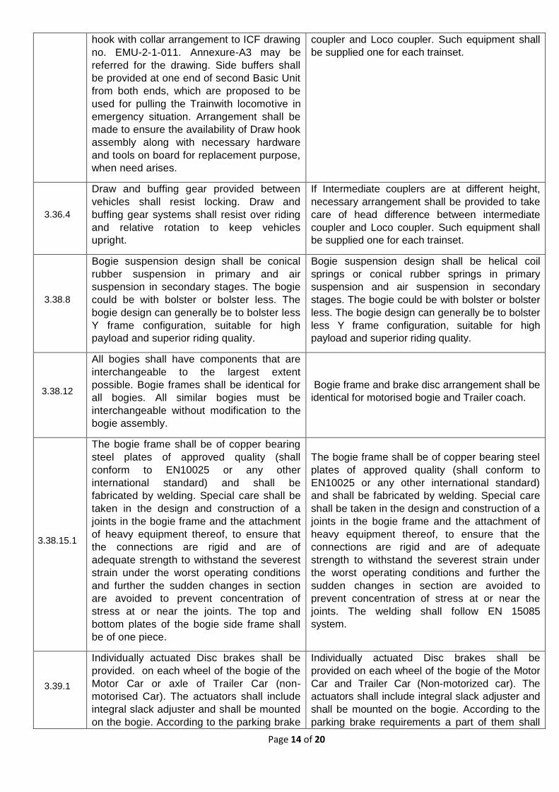
hook with collar arrangement to ICF drawing
no. EMU-2-1-011. Annexure-A3 may be
referred for the drawing. Side buffers shall
be provided at one end of second Basic Unit
from both ends, which are proposed to be
used for pulling the Trainwith locomotive in
emergency situation. Arrangement shall be
made to ensure the availability of Draw hook
assembly along with necessary hardware
and tools on board for replacement purpose,
when need arises.
coupler and Loco coupler. Such equipment shall
be supplied one for each trainset.
3.36.4
Draw and buffing gear provided between
vehicles shall resist locking. Draw and
buffing gear systems shall resist over riding
and relative rotation to keep vehicles
upright.
If Intermediate couplers are at different height,
necessary arrangement shall be provided to take
care of head difference between intermediate
coupler and Loco coupler. Such equipment shall
be supplied one for each trainset.
3.38.8
Bogie suspension design shall be conical
rubber suspension in primary and air
suspension in secondary stages. The bogie
could be with bolster or bolster less. The
bogie design can generally be to bolster less
Y frame configuration, suitable for high
payload and superior riding quality.
Bogie suspension design shall be helical coil
springs or conical rubber springs in primary
suspension and air suspension in secondary
stages. The bogie could be with bolster or bolster
less. The bogie design can generally be to bolster
less Y frame configuration, suitable for high
payload and superior riding quality.
3.38.12
All bogies shall have components that are
interchangeable to the largest extent
possible. Bogie frames shall be identical for
all bogies. All similar bogies must be
interchangeable without modification to the
bogie assembly.
Bogie frame and brake disc arrangement shall be
identical for motorised bogie and Trailer coach.
3.38.15.1
The bogie frame shall be of copper bearing
steel plates of approved quality (shall
conform to EN10025 or any other
international standard) and shall be
fabricated by welding. Special care shall be
taken in the design and construction of a
joints in the bogie frame and the attachment
of heavy equipment thereof, to ensure that
the connections are rigid and are of
adequate strength to withstand the severest
strain under the worst operating conditions
and further the sudden changes in section
are avoided to prevent concentration of
stress at or near the joints. The top and
bottom plates of the bogie side frame shall
be of one piece.
The bogie frame shall be of copper bearing steel
plates of approved quality (shall conform to
EN10025 or any other international standard)
and shall be fabricated by welding. Special care
shall be taken in the design and construction of a
joints in the bogie frame and the attachment of
heavy equipment thereof, to ensure that the
connections are rigid and are of adequate
strength to withstand the severest strain under
the worst operating conditions and further the
sudden changes in section are avoided to
prevent concentration of stress at or near the
joints. The welding shall follow EN 15085
system.
3.39.1
Individually actuated Disc brakes shall be
provided. on each wheel of the bogie of the
Motor Car or axle of Trailer Car (non-
motorised Car). The actuators shall include
integral slack adjuster and shall be mounted
on the bogie. According to the parking brake
Individually actuated Disc brakes shall be
provided on each wheel of the bogie of the Motor
Car and Trailer Car (Non-motorized car). The
actuators shall include integral slack adjuster and
shall be mounted on the bogie. According to the
parking brake requirements a part of them shall
Page 15 of 20
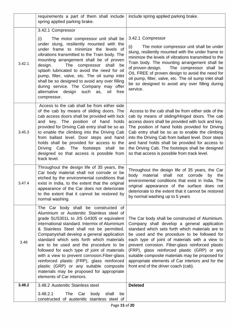
requirements a part of them shall include
spring applied parking brake.
include spring applied parking brake.
3.42.1
3.42.1 Compressor
(i) The motor compressor unit shall be
under slung, resiliently mounted with the
under frame to minimize the levels of
vibrations transmitted to the Train body. The
mounting arrangement shall be of proven
design. The compressor shall be
splash lubricated to avoid the need for oil
pump, filter, valve, etc. The oil sump inlet
shall be so designed to avoid any over filling
during service. The Company may offer
alternative design such as, oil free
compressor.
3.42.1 Compressor
(i) The motor compressor unit shall be under
slung, resiliently mounted with the under frame to
minimize the levels of vibrations transmitted to the
Train body. The mounting arrangement shall be
of proven design. The compressor shall be
OIL FREE of proven design to avoid the need for
oil pump, filter, valve, etc. The oil sump inlet shall
be so designed to avoid any over filling during
service.
3.45.3
Access to the cab shall be from either side
of the cab by means of sliding doors. The
cab access doors shall be provided with lock
and key. The position of hand holds
provided for Driving Cab entry shall be so as
to enable the climbing into the Driving Cab
from ballast level. Door steps and hand
holds shall be provided for access to the
Driving Cab. The footsteps shall be
designed so that access is possible from
track level.
Access to the cab shall be from either side of the
cab by means of sliding/Hinged doors. The cab
access doors shall be provided with lock and key.
The position of hand holds provided for Driving
Cab entry shall be so as to enable the climbing
into the Driving Cab from ballast level. Door steps
and hand holds shall be provided for access to
the Driving Cab. The footsteps shall be designed
so that access is possible from track level.
3.47.4
Throughout the design life of 35 years, the
Car body material shall not corrode or be
etched by the environmental conditions that
exist in India, to the extent that the original
appearance of the Car does not deteriorate
to the extent that it cannot be restored by
normal washing.
Throughout the design life of 35 years, the Car
body material shall not corrode by the
environmental conditions that exist in India. The
original appearance of the surface does not
deteriorate to the extent that it cannot be restored
by normal washing up to 5 years
3.48
The Car body shall be constructed of
Aluminium or Austenitic Stainless steel of
grade SUS301L to JIS G4305 or equivalent
international standard. Intermix of Aluminium
& Stainless Steel shall not be permitted.
Companyshall develop a general application
standard which sets forth which materials
are to be used and the procedure to be
followed for each type of joint of materials
with a view to prevent corrosion.Fiber-glass
reinforced plastic (FRP), glass reinforced
plastic (GRP) or any suitable composite
materials may be proposed for appropriate
elements of Car interiors.
The Car body shall be constructed of Aluminium.
Company shall develop a general application
standard which sets forth which materials are to
be used and the procedure to be followed for
each type of joint of materials with a view to
prevent corrosion. Fiber-glass reinforced plastic
(FRP), glass reinforced plastic (GRP) or any
suitable composite materials may be proposed for
appropriate elements of Car interiors and for the
front end of the driver coach (cab).
3.48.2 3.48.2 Austenitic Stainless steel
3.48.2.1 The Car body shall be
constructed of austenitic stainless steel of
Deleted
Page 16 of 20
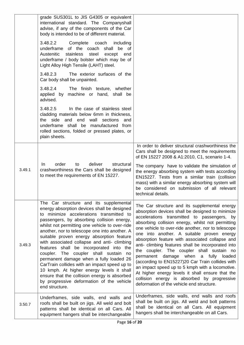
grade SUS301L to JIS G4305 or equivalent
international standard. The Companyshall
advise, if any of the components of the Car
body is intended to be of different material.
3.48.2.2 Complete coach including
underframe of the coach shall be of
Austenitic stainless steel except end
underframe / body bolster which may be of
Light Alloy High Tensile (LAHT) steel.
3.48.2.3 The exterior surfaces of the
Car body shall be unpainted.
3.48.2.4 The finish texture, whether
applied by machine or hand, shall be
advised.
3.48.2.5 In the case of stainless steel
cladding materials below 6mm in thickness,
the side and end wall sections and
underframe shall be manufactured from
rolled sections, folded or pressed plates, or
plain sheets.
3.49.1
In order to deliver structural
crashworthiness the Cars shall be designed
to meet the requirements of EN 15227.
In order to deliver structural crashworthiness the
Cars shall be designed to meet the requirements
of EN 15227 2008 & A1:2010, C1, scenario 1-4.
The company have to validate the simulation of
the energy absorbing system with tests according
EN15227. Tests from a similar train (collision
mass) with a similar energy absorbing system will
be considered on submission of all relevant
technical details.
3.49.3
The Car structure and its supplemental
energy absorption devices shall be designed
to minimize accelerations transmitted to
passengers, by absorbing collision energy,
whilst not permitting one vehicle to over-ride
another, nor to telescope one into another. A
suitable proven energy absorption feature
with associated collapse and anti- climbing
features shall be incorporated into the
coupler. The coupler shall sustain no
permanent damage when a fully loaded 26
CarTrain collides with an impact speed up to
10 kmph. At higher energy levels it shall
ensure that the collision energy is absorbed
by progressive deformation of the vehicle
end structure.
The Car structure and its supplemental energy
absorption devices shall be designed to minimize
accelerations transmitted to passengers, by
absorbing collision energy, whilst not permitting
one vehicle to over-ride another, nor to telescope
one into another. A suitable proven energy
absorption feature with associated collapse and
anti- climbing features shall be incorporated into
the coupler. The coupler shall sustain no
permanent damage when a fully loaded
(according to EN15227)20 Car Train collides with
an impact speed up to 5 kmph with a locomotive.
At higher energy levels it shall ensure that the
collision energy is absorbed by progressive
deformation of the vehicle end structure.
3.50.7
Underframes, side walls, end walls and
roofs shall be built on jigs. All weld and bolt
patterns shall be identical on all Cars. All
equipment hangers shall be interchangeable
Underframes, side walls, end walls and roofs
shall be built on jigs. All weld and bolt patterns
shall be identical on all Cars. All equipment
hangers shall be interchangeable on all Cars.
Page 17 of 20
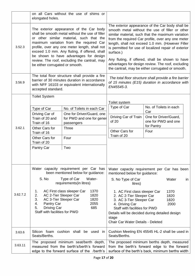
on all Cars without the use of shims or
elongated holes.
3.52.3
The exterior appearance of the Car body
shall be smooth metal without the use of filler
or other similar material, such that the
maximum variation from the required Car
profile, over any one meter length, shall not
exceed 1.0 mm. Any fluting, if offered, shall
be shown to have advantages for design
review. The roof, excluding the cantrail, may
be either corrugated or smooth.
The exterior appearance of the Car body shall be
smooth metal without the use of filler or other
similar material, such that the maximum variation
from the required Car profile, over any one meter
length, shall not exceed 1.0 mm. (However Filler
is permitted for use of localized repair of exterior
surface.)
Any fluting, if offered, shall be shown to have
advantages for design review. The roof, excluding
the cantrail, may be either corrugated or smooth.
3.56.9
The total floor structure shall provide a fire
barrier of 30 minutes duration in accordance
with NFF 16103 or equivalent internationally
accepted standard.
The total floor structure shall provide a fire barrier
of 15 minutes (E15) duration in accordance with
EN45545-3.
3.62.1
Toilet System
Type of Car No. of Toilets in each Car
Driving Car of
Train of 20 and
Train of 16
One for Driver/Guard, one
for PWD and one for general
passengers
Other Cars for
Train of 16
Three
Other Cars for
Train of 20
Four
Pantry Car Two
Toilet system
Type of Car No. of Toilets in each
Car
Driving Car of Train
of 20
One for Driver/Guard,
one for PWD and one
for Pantry
Other Cars for
Train of 20
Four
3.62.7.2
Water capacity requirement per Car has been mentioned below for guidance:
S. No Type of Car Water- requirements(in litres)
1. AC First class sleeper Car 1370 2. AC 2-Tier Sleeper Car 1820 3. AC 3-Tier Sleeper Car 1820 4. Pantry Car 2055 5. Driving Car 685 Staff with facilities for PWD
Water capacity requirement per Car has been mentioned below for guidance:
S. No Type of Car Water in litres)
1. AC First class sleeper Car 1370 2. AC 2-Tier Sleeper Car 1820 3. AC 3-Tier Sleeper Car 1820 4. Driving Car 2000 Staff with facilities for PWD
Details will be decided during detailed design
stage
Chair Car Water Details - Deleted
3.63.6 Silicon foam cushion shall be used in Seats/Berths.
Cushion Meeting EN 45545 HL-2 shall be used in Seats/Berths.
3.63.11 The proposed minimum seat/berth depth,
measured from the berth’s/berth’s forward
edge to the forward surface of the /berth’s
The proposed minimum berths depth, measured
from the berth’s forward edge to the forward
surface of the berth’s back, minimum berths width
Page 18 of 20
back, minimum seat/berth width and leg
room shall be submitted by the Company for
the design review.
and leg room shall be submitted by the Company
for the design review.
3.63.13
The Cars with seating arrangement shall be
provided with aesthetically designed
comfortable seats with a rigid surface. The
seats shall have a reclining function. The
seats shall be designed to prevent slipping
when the Train accelerates and decelerates.
The material used for seat covering should
not become readily soiled, shall be easily
cleaned, impervious and chemically
unaffected by water, paint, human waste,
graffiti removers, wash plant solution,
cleaning solution, food and drink spills. Seat
covers shall be removable to allow for quick
replacement or cleaning. Seats shall be
ergonomically designed to accommodate
range passengers from 5th percentile of
Indian female and 95th percentile of Indian
adult male.
The seating arrangement inside the Car
shall be planned ensuring the following:
• In Executive Chair Car, the leg space
and aisle are at least 450 mm and 640 mm
respectively.
• In Chair Car, the leg space and aisle
are at least 327 mm and 556 mm
respectively.
There shall be no seating in doorway
vestibule areas. The design of seat and its
positions in the Car shall minimize the risk of
injury to passengers as they sit or move
across a seat. The space underneath the
seats shall be clearly visible. Seat modules
provided in similar position in a particular
type of Car shall be interchangeable. Only
one style of module should be used in a
particular type of Car throughout the Train.
As a standard all the seats of the Cars shall
have the following equipment:
• Armrest
• Table (foldable)
• Magazine net
• Foot rest
• Velcro for antimacassar
• Textile upholstery
Deleted
Page 19 of 20
3.66
Sub-Pantry The Cars shall have the following sub-pantry equipment: (i) Bottle cooler cum deep freezer (ii) Water boiler of minimum 20 liter capacity. (iii) Hot case (Veg & non-veg compartment)
for keeping minimum 75 casseroles of approx. size 190 (L) x 140 (W) x 4 (H) mm each.
(iv) Soup warmer. (v) Trolley size suitable dimensions for
serving the passengers (vi) Adequate waste disposal arrangement (vii) The sub-pantry equipment shall work on
the 230 V AC, single phase, sinusoidal 50HZ auxiliary converter supply.
The sub - pantry load shall be suitably distributed on the three phases of above supply. However, further details and layout of Sub-pantry equipment shall be finalized at design stage.
Deleted.
3.67.2.7
All windows shall be highly resistant to
damage arising from the impact of ballast.
All windows shall be able to withstand
without shattering impact from ballast up to
75 mm in size at speeds of up to the
maximum service speed of 160 Km/h.
All windows shall be highly resistant to damage
arising from the impact of ballast. All windows
shall be able to withstand impact from ballast up
to 75 mm in size at speeds of up to the maximum
service speed of 160 Km/h. Cracks are allowed,
but ballast shall not enter inside train.
3.65.3.8
The design of all parts and components of
doors shall meet the Fire prevention
requirements of UIC 564-2.
The design of all parts and components of doors
shall meet the Fire prevention requirements of
EN45545.
3.65.4.9
The design of all parts and components of
lavatory doors shall meet the Fire prevention
requirements of UIC sheet 564-2.
The design of all parts and components of
lavatory doors shall meet the Fire prevention
requirements of EN 45545.
3.67.3.4 Double leaf vestibule doors should have
smooth running without jerks.
Double or single leaf vestibule doors should
have smooth running without jerks.
3.67.4.9
The design of all parts and components of
lavatory doors shall meet the Fire prevention
requirements of UIC sheet 564-2.
The design of all parts and components of
lavatory doors shall meet the Fire prevention
requirements of EN 45545.
3.68.4.6
In the event of a failure of the dynamic
brake, the friction brake shall be capable of
carrying out three consecutive emergency
brake applications from maximum speed to
standstill of a rake in loaded condition. The
rake shall be deemed to then accelerate at
its maximum rate up to maximum speed
after each stop. With three consecutive full
service brake also, the temperature rise of
Propulsion Equipment should be within the
specified limit.
In the event of a failure of the dynamic brake, the
friction brake shall be capable of carrying out
emergency brake applications from maximum
speed to standstill of a rake in loaded condition.
The rake shall be deemed to then accelerate at
its maximum rate up to maximum speed. With
three consecutive full service brake also, the
temperature rise of Propulsion Equipment should
be within the specified limit.
Page 20 of 20
3.68.6.2
Emergency brake is applied by friction brake
system. Electric regenerative brake shall be
isolated during emergency braking.
Emergency braking distance as specified in
Clause2.6.4 of these Specification and
Standards shall be achieved from 160kmph
to 0kmph for all loading condition on level
tangent track.
Emergency brake is applied by friction brake
system. Emergency braking distance as
specified in Clause2.6.4 of these Specification
and Standards shall be achieved from 160kmph
to 0kmph for all loading condition on level tangent
track.
3.68.6.9
The friction brake system shall be rated to,
and have sufficient thermal capacity to
safely complete three successive
accelerations and emergency brake cycles,
with no interval between each cycle on
loaded Train. Each cycle shall comprise a
full acceleration from standstill to 160kmph
followed by the application of emergency
brake to standstill. On the completion of the
three cycles, the brake system shall show
no abnormalities. The requirement shall be
demonstrated during testing. Thereafter the
Train friction brake shall have sufficient
thermal capacity to be able to complete its
journey without regenerative brakes.
The friction brake system shall be rated to, and
have sufficient thermal capacity to safely
complete two successive accelerations and
emergency brake cycles, with no interval
between each cycle on loaded Train. Each cycle
shall comprise a full acceleration from standstill
to 160kmph followed by the application of
emergency brake to standstill. On the
completion of the two cycles, the brake system
shall show no abnormalities. The requirement
shall be demonstrated during testing. Thereafter
the Train friction brake shall have sufficient
thermal capacity to be able to complete its
journey without regenerative brakes.
3.71
Pantry Car (for Train of 20)
3.71.1 Pantry equipment’s like Freezer,
Deep Freezer, Bottle Cooler, Hot Case,
Induction heating based cooking range, Hot
water Boiler, Refrigerator, Electric Chimney
etc. similar to the existing pantry
equipment’s provided in LHB type coach Hot
Buffet Car on Indian Railways. However,
further details and layout of Pantry Car
equipment shall be finalized at design stage.
3.71.2 Pantry shall be equipped with
Modern Induction heating based cooking
system and service tables.
3.71.3 Adequate no. of sink and insect killer
shall be provided in pantry area.
3.71.4 Pantry shall fulfill the ergonomical
and Hygienic requirements.
3.71.5 Environmental requirements with
respect to temperature, humidity and
corrosions shall be taken into consideration.
3.71.6 Cut-outs for smoke emission through
Electric Chimney shall be provided in the
side wall of each cooking range / Induction
heating based cooking range as provided in
conventional Rajdhani Express Trains on IR.
Pantry Car (for Train of 20)
3.71.1 Pantry equipment’s like Freezer, Deep
Freezer, Bottle Cooler, Hot Case, Hot water
Boiler, Refrigerator, etc. similar to the existing
pantry equipment’s provided in LHB type coach
Hot Buffet Car on Indian Railways. However,
further details and layout of Pantry Car
equipment shall be finalized at design stage.
3.71.2 Adequate no. of sink and insect killer
shall be provided in pantry area.
3.71.3 Pantry shall fulfill the ergonomical and
Hygienic requirements.
3.71.4 Environmental requirements with respect
to temperature, humidity and corrosions shall be
taken into consideration.