Embed Size (px)
Citation preview

RCP2/RCP2CR/RCP2W/RCS2 Actuator Rotary Type/Hollowed Rotary Type
First Step Guide Sixth Edition
Thank you for purchasing our product. Make sure to read the Safety Guide and detailed Instruction Manual (DVD) included with the product in addition to this First Step Guide to ensure correct use. This Instruction Manual is original. • Using or copying all or part of this Instruction Manual without permission is prohibited. • The company names, names of products and trademarks of each company shown in the sentences are registered
trademarks.
Product Check This product is comprised of the following parts if it is of standard configuration. If you find any fault in the contained model or any missing parts, contact us or our distributor. 1. Parts (The option is excluded.)
No. Part Name Model Remarks 1 Actuator Main Body Refer to “How to read the model
plate”, “How to read the model.”
Accessories 2 Motor • Encoder Cable*1 3 First Step Guide 4 Instruction Manual (DVD) 5 Safety Guide
*1 Enclosed motor cable and encoder cable differ depending on the model and the applied controller. Please refer to [Wiring] for the applicable cables.
2. How to read the model plate 3. How to read the model 3.1 RCP2 Type
3.2 RCS2 Type
Precautions in Handling 1. Handling of the Packed Product
Unless otherwise specified, the actuator is shipped with each axis packaged separately. • Do not damage or drop. The package is not supplied with any special treatment that enables it to resist
an impact caused by a drop or crash. • If the shipping box is to be left standing, it should be in a horizontal position. Follow the instruction if
there is any for the packaging condition. • Do not step or sit on the package. • Do not put any load that may cause a deformation or breakage of the package.
2 Handling of Robot without Package • Do not carry the actuator by holding the cable, or do not move it by pulling the cable. • When carrying the actuator, exercise caution not to bump it against nearby objects or structures. • Do not give any excessive force to any of the sections in the actuator.
Installation Environment, Storage Environment 1. Installation Environment
An environment that satisfies the following conditions is required during installation. • There should be no direct sunlight. • Any radiant heat from a large heat source such as a heat treatment furnace should not be directed at
the machine main body. • The ambient temperature should be 0 to 40°C. • The relative humidity should be 85% or less. There should not be dew condensation. • When the air purging was conducted possesses the water durability of IP54 protection structure.
(Dustproof/Splash proof type) • There should be no corrosive gas or flammable gas. • There should be no flammable dust or ignitable liquid in the surroundings. • Oil mist or cutting liquid should not be directed at the machine. • Chemical liquid should not be splashed on it. • An impact or vibration should not be transmitted to it. • There should be no strong electromagnetic waves, ultraviolet rays or radiation. • The actuator should not be installed where it gets dipped in liquid. • The working space required for maintenance or inspection should be secured.
2. Storage and Preservation Environment The storage and preservation environment should comply with the same standards as those for the installation environment. In particular, when the machine is to be stored and preserved for a long time, pay close attention to environmental conditions so that no dew condensation forms. Unless specially specified, moisture absorbency protection is not included in the package when the machine is delivered. In the case that the machine is to be stored and preserved in an environment where dew condensation is anticipated, take the condensation preventive measures from outside of the entire package, or directly after opening the package. For storage and preservation temperature, the machine withstands temperatures up to 60°C for a short time, but in the case of the storage and preservation period of 1 month or more, control the temperature to 50°C or less. Storage and preservation should be performed in the horizontal condition.
Names of the Parts 1. Standard specification RCP2 1.1 Small Vertical Type, 330-degree Rotation Specification (RTBS) and Multi-Rotation
Specification (RTBSL)
1.2 Small Flat Type, 330-degree Rotation Specification (RTCS) and Multi-Rotation
Specification (RTCSL)
1.3 Medium Vertical Type, 330-degree Rotation Specification (RTB) and Multi-Rotation Specification (RTBL)
1.4 Brake-Equipped Medium Vertical Type, 330-degree Rotation Specification (RTB) and Multi-Rotation Specification (RTBL)
R C P 2 - R T B S - I - 2 0 P - 3 0 - 3 3 0 - P 1 - S - N M - * <Series>
RCP2 : Standard Specification RCP2CR : Cleanroom Specification RCP2W : Dust-proof/Splash-proof
Specification <Type>
RTBS : Small Vertical Type 330-degree Rotation Specification
RTBSL : Small Vertical Type Multi-Rotation Specification
RTCS : Small Flat Type 330-degree Rotation Specification
RTCSL : Small Flat Type Multi-Rotation Specification
RTB : Medium Vertical Type 330-degree Rotation Specification
RTBL : Medium Vertical Type Multi-Rotation Specification
RTC : Medium Flat Type 330-degree Rotation Specification
RTCL : Medium Flat Type Multi-Rotation Specification
RTBB : Large Vertical Type 330-degree Rotation Specification
RTBBL : Large Vertical Type Multi-Rotation Specification
RTCB : Large Flat Type 330-degree Rotation Specification
RTCBL : Large Flat Type Multi-Rotation Specification
<Encoder Type> I : Incremental
<Motor Type> 20P : Pulse Motor 20 □Size 28P : Pulse Motor 28 □Size 35P : Pulse Motor 35 □Size
Identification for IAI use only (Note1) <Option> NM : Reversed Home
Specification SA : Shaft Adapter TA : Table Adapter B : Brake <Cable Length> N : None P : 1m S : 3m M : 5m X□□ : Specified Length
(Example: X07=7m) <Controller> P1 : PCON
(Except for PCON-CA) RPCON, PSEL P3 : PCON-CA, PMEC PSEP, MSEP, MSEL <Rotation Angle> 330 : 330 Degrees
(RTBS, RTB, RTBB, RTCS, RTC, RTCB)
360 : 360 Degrees (RTBSL, RTBL, RTBBL, RTCSL, RTCL, RTCBL)
<Gear Ratio> 20 : 1/20 30 : 1/30 45 : 1/45
Model
Serial number
MODEL RCP2-RTBS-I-20P-30-330-P1-S-NM
SERIAL No. 800061901 MADE IN JAPAN
R C S 2 - R T 6 - I - 6 0 - 1 8 - 3 0 0 - T 1 - S - L<Series> <Type> RT6 : Motor Straight Type RT6R : Motor Reversing Type RT7R : Motor Reversing Hollowed Shaft Type RTC8L : Hollowed Small Standard Type RTC8HL : Hollowed Small High Output Type RTC10L : Hollowed Medium Type RTC12L : Hollowed Large Type <Encoder Type> A : Absolute I : Incremental <Motor Type> 12 : Servo-Motor 12W 20 : Servo-Motor 20W 60 : Servo-Motor 60W 150 : Servo-Motor 150W <Gear Ratio> 4 : 1/4 15 : 1/15 18 : 1/18 24 : 1/24 30 : 1/30
<Option> L : Limit Switch
(Standard Equipment) B : Brake NM : Reversed Home
Specification CE : CE Marking
<Cable Length> N : None P : 1m S : 3m M : 5m X□□ : Specified Length
(Example: X07=7m) R□□ : Robot Cable
(Example: R05=5m) <Controller> T1 : XSEL-J/K T2 : SCON SSEL XSEL-P/Q <Rotation Angle> 300 : 300 degrees 360 : 360 degrees
[Refer to the Catalog or Instruction Manual (DVD) for specification details.]
Warning : Operation of this equipment requires detailed installation and operation instructions which are provided on the DVD Manual included in the box this device was packaged in. It should be retained with this device at all times.
A copy of the DVD Manual can be requested by contacting your nearest IAI Sales Office listed at the back cover of the Instruction Manual or on the First Step Guide.
FlangeOutput Shaft
Rear Cover
Front Cover
Actuator Cable
Flange Output Shaft
Rear Cover
Frame
Front Cover
Actuator Cable
[Refer to the Catalog or Instruction Manual (DVD) for specification details.]
Flange Output Shaft
Rear Cover
Frame
Front Cover
Actuator Cable
Brake Housing
1.5 Medium Flat Type, 330-degree Rotation Specification (RTC) and Multi-Rotation Specification (RTCL)
1.6 Brake-Equipped Medium Flat Type, 330-degree Rotation Specification (RTC) and Multi-Rotation Specification (RTCL)
1.7 Large Vertical Type, 330-degree Rotation Specification (RTBB) and Multi-Rotation
Specification (RTBBL)
1.8 Brake-Equipped Large Vertical Type, 330-degree Rotation Specification (RTBB) and Multi-Rotation Specification (RTBBL)
1.9 Large Flat Type, 330-degree Rotation Specification (RTCB) and Multi-Rotation Specification (RTCBL)
1.10 Brake-Equipped Large Flat Type, 330-degree Rotation Specification (RTCB) and
Multi-Rotation Specification (RTCBL) 2. Cleanroom specification RCP2CR, Dust and Splash-Proof specification RCP2W 2.1 Small Vertical Type, 330-degree Rotation Specification (RTBS) and Multi-Rotation
Specification (RTBSL)
2.2 Small Flat Type, 330-degree Rotation Specification (RTCS) and Multi-Rotation Specification (RTCSL)
2.3 Medium Vertical Type, 330-degree Rotation Specification (RTB) and Multi-Rotation Specification (RTBL)
2.4 Brake-Equipped Medium Vertical Type, 330-degree Rotation Specification (RTB) and Multi-Rotation Specification (RTBL)
2.5 Medium Flat Type, 330-degree Rotation Specification (RTC) and Multi-Rotation
Specification (RTCL)
2.6 Brake-Equipped Medium Flat Type, 330-degree Rotation Specification (RTC) and Multi-Rotation Specification (RTCL)
FlangeOutput Shaft
Rear Cover
Frame
Front Cover
Actuator Cable
Flange Output Shaft
Rear Cover
Frame
Front Cover
Actuator Cable
FlangeOutput Shaft
Rear CoverFrame
Front Cover
Actuator Cable
Output ShaftFlange
Rear Cover
Air Joint
Actuator Cable
Front Cover
Frame
Output Shaft Flange
Rear Cover
Air Joint
Actuator Cable
Front Cover
Frame
Output ShaftFlange
Rear Cover
Air Joint
Actuator Cable
Front Cover
Frame
OutputShaft
Flange
Rear Cover
Air Joint
Actuator Cable
Front Cover
Frame
Brake Housing
Brake Housing
Brake Housing
Brake Housing
Brake Housing

2.7 Large Vertical Type, 330-degree Rotation Specification (RTBB) and Multi-Rotation Specification (RTBBL)
2.8 Brake-Equipped Large Vertical Type, 330-degree Rotation Specification (RTBB) and Multi-Rotation Specification (RTBBL)
2.9 Large Flat Type, 330-degree Rotation Specification (RTCB) and Multi-Rotation
Specification (RTCBL)
2.10 Brake-Equipped Large Flat Type, 330-degree Rotation Specification (RTCB) and
Multi-Rotation Specification (RTCBL)
3. RCS2 3.1 Rotary Type 3.1.1 Motor Straight Type (RCS2-RT6)
3.1.2 Motor Reversing Type (RCS2-RT6R)
3.1.3 Motor Reversing Hollowed Shaft Type (RCS2-RT7R)
3.2 Hollowed Rotary Type
Refer to the Catalog or Instruction Manual (DVD) for the dimensioned drawing and the detailed appearance drawing.
Attachment
Refer to the Instruction Manual (DVD) for the attachments of the actuator and loads. [Precautions for Attachments] No. Item Precautions 1 Attachment Surface • The actuator mounting surface and other surfaces that are used as a
datum should be flat enough with an accuracy of machining or equivalent treatment, and the flatness of the mounting surface needs to be ±0.05mm/m or less.
• Secure the space where maintenance work can be performed.
2 Bolts to be used • For the bolts to be used, a high-tensile bolt complying with ISO-10.9 or more is recommended.
• If using the tapped holes, use screws with the thread length dimension being less than the effective depth of the holes.
• In case the tapped hole is a through hole, be careful so the screw tip does not exceed the surface of the tapped hole.
• For the actuator mounting, use a bolt with the dimension of its effective mating length to the tapped hole size as stated below. If tapped hole in steel → thread length same as nominal diameter If tapped hole in aluminum → thread length 2 times longer than nominal diameter
3 Tightening Torque • Please follow the specification values stated in the Instruction Manual (DVD) for the tightening torque. Failure to do so may cause an operation problem.
4 Moment of Inertia Load Moment Thrust Load
• Please follow the specified values stated in the Instruction Manual (DVD) for the moment of inertia, load moment and thrust load. Failure to do so may not only cause vibration and abnormal noise, but it may also shorten the product life extraordinarily.
Wiring For the controller, only the dedicated controller manufactured by our company can be used. Use the dedicated cable enclosed in the package when connecting the actuator and the controller. 1. Standard specification RCP2 1.1 Small Vertical Type (RTBS, RTBSL)
Small Flat Type (RTCS, RTCSL) [Connection to the PCON (Except for PCON-CA), PSEL Controller]
Dedicated Connection Cable • CB-PCS-MPA□□□ □□□ shows the cable length. The max. length should be 20m.
Example) 080=8m
[Connection to the PCON-CA, MSEP, PMEC, PSEP, MSEL Controller]
Dedicated Connection Cable CB-RPSEP-MPA□□□ □□□ shows the cable length. The max. length should be 10m.
Example) 080=8m
r
r = 68mm or more (Movable Use)r = 34mm or more (Fixed Use)
Dedicated Connection Cable(Connect RCP2 with the dedicated controller)
Dedicated ControllerPMECPSEP
Driving Shaft Frame Motor Cover End Cover
Motor Bracket Actuator Cable
Pulley Cover
FlangeActuator Cable
Driving Shaft Frame
Motor Cover
Pulley Cover
FlangeActuator Cable
Driving Shaft Frame
Motor Cover
Cylinder
Rear Cover
Output Shaft
Front Cover
Frame
Actuator Cable
Output ShaftFlangeRear Cover
Air Joint
Actuator Cable
Front Cover
Frame6
OutputShaft
Flange
Rear Cover
Air Joint
Actuator Cable
Front Cover
Frame
Dedicated ControllerPCONPSEL
r
r = 84 mm or more (Movable Use)r = 42 mm or more (Fixed Use)
Dedicated Connection Cable(Connect RCP2 with the dedicated controller)
Brake Housing
Brake Housing

1.2 Medium Vertical Type (RTB, RTBL) Medium Flat Type (RTC, RTCL) Large Vertical Type (RTBB, RTBBL) Large Flat Type (RTCB, RTCBL)
[Connection to the PCON (Except for PCON-CA), PSEL Controller]
Dedicated Connection Cable • Motor Cable (Robot Cable) CB-RCP2-MA□□□ • Encoder Cable CB-RCP2-PB□□□/Encoder Cable Robot Cable CB-RCP2-PB□□□-RB □□□ shows the cable length. The max. length should be 20m.
Example) 080=8m
[Connection to the PCON-CA, MSEP, PMEC, PSEP, MSEL Controller]
Dedicated Connection Cable • Motor Cable (Robot Cable) CB-PSEP-MPA□□□ □□□ shows the cable length. The max. length should be 10m.
Example) 080=8m
2. Cleanroom specification RCP2CR, Dust and Splash-Proof specification RCP2W [Connection to the PCON (Except for PCON-CA), PSEL Controller]
Dedicated Connection Cable • Motor, Encoder Integrated Robot Cables CB-PCS2-MPA□□□ □□□ shows the cable length. The max. length should be 20m.
Example) 080=8m
[Connection to the PCON-CA, MSEP, PMEC, PSEP, MSEL Controller]
Dedicated Connection Cable • Motor, Encoder Integrated Cables CB-CAN-MPA□□□ • Motor, Encoder Integrated Robot Cables CB-CAN-MPA□□□-RB □□□ shows the cable length. The max. length should be 20m.
Example) 080=8m
3. RCS2 The drawing below is that of Rotary Type as an example.
[Connection to the SCON, SSEL Controller]
Dedicated Connection Cable • Motor Cable CB-RCC-MA□□□/Motor Cable Robot Cable CB-RCC-MA□□□-RB • Encoder Cable CB-RCS2-PLA□□□/Encoder Cable Robot Cable CB-X2-PLA□□□ □□□ shows the cable length. The max. length should be 30m.
Example) 080=8m
[Connection to the X-SEL Controller]
Dedicated Connection Cable • Motor Cable CB-RCC-MA□□□/Motor Cable Robot Cable CB-RCC-MA□□□-RB • Encoder Cable for XSEL-J/K Type CB-RCBC-PA□□□
/ Encoder Cable Robot Cable for XSEL-J/K Type CB-RCBC-PA□□□-RB • Encoder Cable for XSEL-P/Q Type CB-RCS2-PLA□□□
/ Encoder Cable Robot Cable for XSEL-P/Q Type CB-X2-PLA□□□ □□□ shows the cable length. The max. length should be 15m. The max. length for other cables is 20m.
Example) 080=8m (Note) Hollowed Rotary cannot be operated with a XSEL-J/K controller.
[Prohibited Items in the Cable Processing] • Do not pull or bend forcibly the cable so as not to give any extra load or tension to the
cable. • Do not process the cable for extension or shortening by means of cutting out,
combination or connecting with another cable. • Do not let the cable flex at a single point. • Do not let the cable bend, kink or twist. • Do not pull the cable with a strong force. • Do not let the cable receive a turning force at a single point. • Do not pinch, drop a heavy object onto or cut the cable. • When fixing the cable, provide a moderate slack and do not tension it too tight. • Separate the I/O line, communication line and power line from each other.
Arrange so that such lines are independently routed in the duct.
Steel Strap(Piano Wire)
Tie them up softly.
Do not use spiral tube in any position where cables are bent frequently.
Power LineDuct
I/O Line(Flat Cable, etc.)
rr
Dedicated Connection Cable(Connect RCP2 with the dedicated controller)
Robot Cabler = 54mm or more (Movable Use)Standard Cabler = 75mm or more (Fixed Use)Apply a robot cable for moveable area.
Dedicated ControllerPCONPSEL
r
Dedicated Connection Cable(Connect RCP2 with the dedicated controller)
r = 84mm or more (Movable Use)r = 42mm or more (Fixed Use)Dedicated Controller
PMECPSEP
rr
RCS2 Dedicated Connection Cable(Connect RCS2 with the dedicated controller)
Robot Cabler = 58mm or more (Movable Use)Standard Cabler = 93mm or more (Fixed Use)Apply a robot cable for moveable area.
Dedicated ControllerSCONSSEL
rr
RCS2Dedicated Connection Cable(Connect RCS2 with the dedicated controller)
Robot Cabler = 58mm or more (Movable Use)Standard Cabler = 93mm or more (Fixed Use)Apply a robot cable for moveable area.
Dedicated ControllerX-SEL
RCP2CR, RCP2W Rotary
Dedicated Connection Cable(Connect RCP2CR, RCP2W with the dedicated controller)
Robot Cable CB-PCS2-MPA□□□ r = 68 mm or more (Movable Use)
Dedicated Controller PSEL PCON (Except for PCON-CA)
RCP2CR, RCP2W Rotary
Dedicated Connection Cable(Connect RCP2CR, RCP2W with the dedicated controller)
Robot Cable CB-CAN-MPA□□□-RB
Dedicated Controller PCON-CA MSEP PMEC PSEP
more than 5m r = 73 mm or more (Movable Use)
5 mm or less r = 85 mm or more (Fixed Use)more than 5m r = 91 mm or more (Fixed Use)
5 mm or less r = 68 mm or more (Movable Use)
Standard Cable CB-CAN-MPA□□□
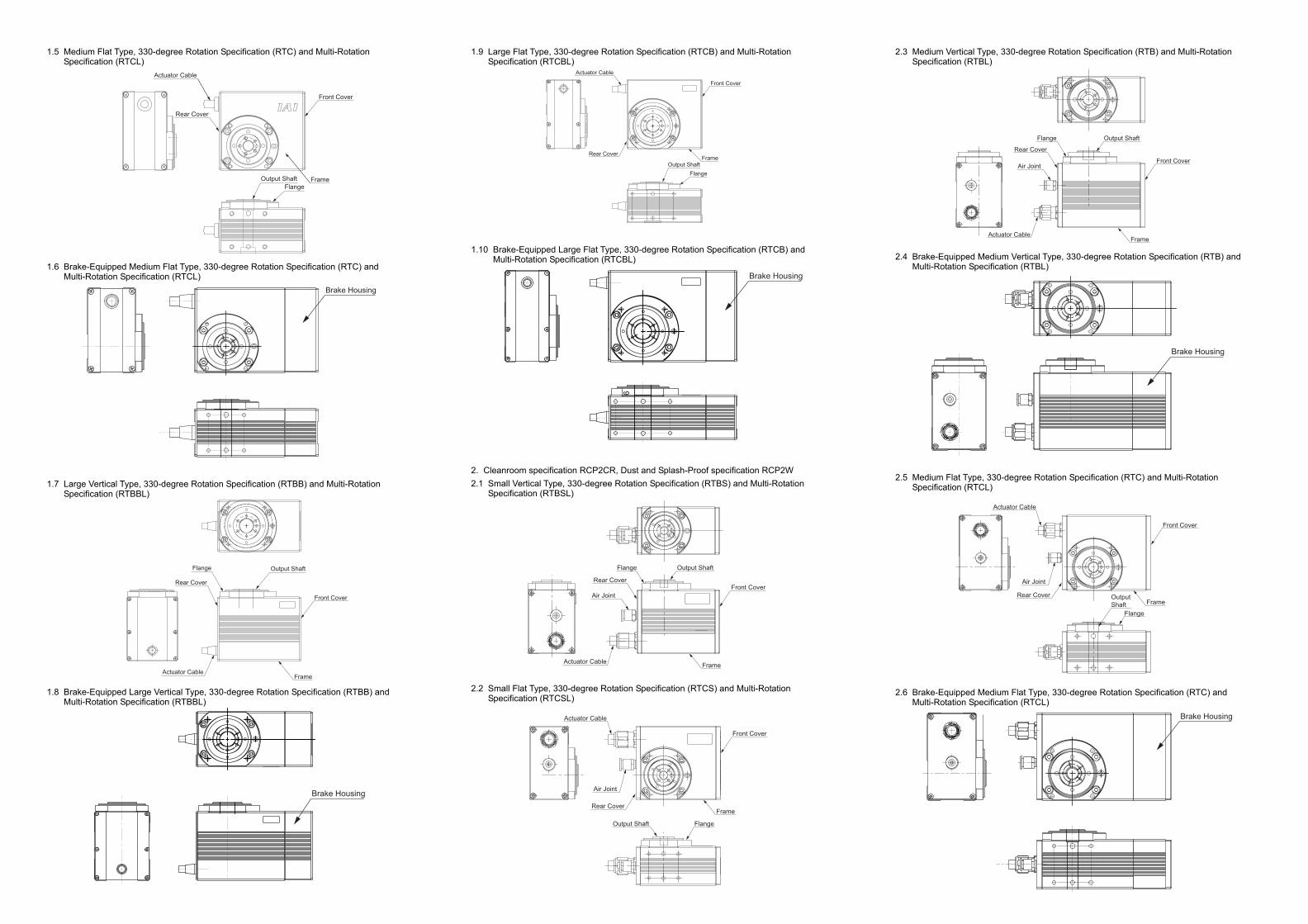
Follow the instructions below when using a cable track. • If there is an indication to the cable for the space factor in a cable track, refer to the wiring instruction
given by the supplier when storing the cable in the cable track. • Avoid the cables to get twined or twisted in the cable track, and also to have the cables move freely
and do not tie them up. (Arrange the wiring so the cables are not to be pulled when bent.) Do not pile up cables. It may cause faster abrasion of the sheaths or cable breakage.
Note: • When the cable is connected or disconnected, make sure to turn off the power to the controller.
When the cable is connected or disconnected with the controller power turned ON, it might cause a malfunction of the actuator and result in a serious injury or damage to the machinery.
• When the connector connection is not correct, it would be dangerous because of a malfunction of the actuator. Make sure to confirm that the connector is connected correctly.
Head Office: 577-1 Obane Shimizu-KU Shizuoka City Shizuoka 424-0103, JapanTEL +81-54-364-5105 FAX +81-54-364-2589
website: www.iai-robot.co.jp/
Ober der Röth 4, D-65824 Schwalbach am Taunus, GermanyTEL 06196-88950 FAX 06196-889524
SHANGHAI JIAHUA BUSINESS CENTER A8-303, 808, Hongqiao Rd. Shanghai 200030, ChinaTEL 021-6448-4753 FAX 021-6448-3992
website: www.iai-robot.com
Technical Support available in USA, Europe and China
Head Office: 2690 W. 237th Street, Torrance, CA 90505TEL (310) 891-6015 FAX (310) 891-0815
Chicago Office: 110 East State Parkway, Schaumburg, IL 60173TEL(847) 908-1400 FAX (847) 908-1399
TEL (678) 354-9470 FAX (678) 354-9471website: www.intelligentactuator.com
Atlanta Office: 1220 Kennestone Circle, Suite 108, Marietta, GA 30066
825 PhairojKijja Tower 12th Floor, Bangna-Trad RD., Bangna, Bangna, Bangkok 10260, ThailandTEL +66-2-361-4458 FAX +66-2-361-4456
Manual No.: ME3699-6A