Embed Size (px)
Citation preview

KELLY MANUFACTURING COMPANY555 SOUTH TOPEKAWICHITA, KS 67202
(316) 265-6868FAX (316) 265-6687
KELLYMFG.COM
Rev B August 26, 2021
KELLY MANUFACTURING COMPANY
KMC
KMC PUBLICATION NO. 1401-7
RCA2610-3P SERIES
P/N: 102-0403-15-17 & 102-0403-15-18
INSTALLATION/OPERATION GUIDE


RCA2610-3P Mini6 Installation/Operation Guide
Page 1 of 17Rev B
KELLY MANUFACTURING COMPANY
KMC
KMC Publication No.1401-7
TABLE OF CONTENTS PAGESECTION 1 INSTRUMENT DESCRIPTION 2 1.1 General Description ...................................................................... 2 1.2 Physical Description ..................................................................... 2 SECTION 2 INSTALLATION 3 2.1 General Information ...................................................................... 3 2.2 Handling ....................................................................................... 3 2.3 Pre-Installation Inspection ............................................................ 3 2.4 Installation .................................................................................... 3
SECTION 3 INITIAL SETUP/CALIBRATION 5 3.1 Setup/Configuration...................................................................... 5 3.2 Calibration .................................................................................... 6 3.3 Initial Flight/Flight Test .................................................................. 7
SECTION 4 OPERATION GUIDE 8 4.1 Primary Display Features ............................................................. 8 4.2 Status Displays ............................................................................. 9 4.3 Pre-Flight Procedures ................................................................... 9 4.4 In Flight Procedures ..................................................................... 10 4.4.1 Flight Menu .................................................................................. 10 4.4.2 Pitch Sync Activation ................................................................... 12 4.4.3 Dimmer ........................................................................................ 12 4.5 Flight Limitations ......................................................................... 13 4.6 Emergency Procedures ............................................................... 13 4.7 Battery Backup ............................................................................ 14 4.8 Battery Replacement ................................................................... 14 SECTION 5 GENERAL INFORMATION 15 5.1 Instrument Care ........................................................................... 15 5.2 Frequently Asked Questions (FAQs) ........................................... 15
APPENDIX A DO-160G ENVIRONMENTAL QUALIFICATION FORM 16
APPENDIX B INSTRUCTIONS FOR AIR WORTHINESS 17
LIST OF ILLUSTRATIONS Figure 2.1, General Dimensions .............................................................. 4 Figure3.1,ConfigurationMenu ............................................................... 5 Figure 3.2, Diagnostics Screen ............................................................... 6 Figure 4.1, Primary Display Features ...................................................... 8 Figure 4.2, Rate of Turn & Vertical Speed Indication............................... 9 Figure 4.3, Status Displays ...................................................................... 9 Figure 4.5, Pitch Sync ............................................................................ 12 Figure 4.6, Dimmer Controls .................................................................. 13 Figure 4.7, Battery Replacement ............................................................ 14
LIST OF TABLES Table 1.1, Leading Particulars ................................................................. 2
REVISION DETAIL
REVISION DATE DETAIL
A 06/07/2021 Initial Release
B 08/26/2021 Updated Software version (Table 1.1), and Flight Limitations (page 13).

Page 2 of 17
RCA2610-3P Mini6 Installation/Operation Guide
Rev B
KELLY MANUFACTURING COMPANY
KMC
KMC Publication No.1401-7
SECTION 1: INSTRUMENT DESCRIPTION
1.1 GENERAL DESCRIPTION
The RCA2610-3P Mini6 is a Digital Multi-Function Indicator (MFI) with a built-in battery backup. The display consists of an Attitude, Heading, Altimeter, Airspeed, Rate of Climb, and Turn and Slip indicator. Each function can be added or subtracted to the display and can be individually customized by the user.
Because the Mini6 has no mechanical gyroscope, it is much more stable than traditional horizons. The unit is designed to work in 360 degrees of pitch and roll and, unlike a mechanical unit, the Mini6 can tolerate angles in pitch and roll that would cause a mechanical gyroscopic unit to tumble.
1.2 PHYSICAL DESCRIPTION
The Mini6isatotallyDigitalIndicatorthatfitsinthestandard3-inchpanelcutoutwithoutanyspecialmodificationtothepanel.(See table 1.1 leading particulars below).
PART NUMBERS ...................................................................................................... StandardConfiguration:102-0403-15-17 NVISconfiguration:102-0403-15-18
OPERATING VOLTAGE .......................................................................................................................................... 9 to 32VDC
RUNNING CURRENT ...................................................................................... (14VDC SYSTEM) ................. 0.35 AMP MAX (28VDC SYSTEM) ................. 0.20 AMP MAX
CIRCUIT BREAKER SIZE............................................................................................................................................... 1 AMP
SETTLING ERROR ........................................................................................................... 1º MAXIMUM IN ROLL AND PITCH
OPERATING TEMPERATURE RANGE ............................................................................................................ -20º TO +55º C
MATING CONNECTOR ........................................................................................................MS3116E8-4S OR EQUIVALENT
WEIGHT ............................................................................................................................................................8.3 oz (2353 g)
DISPLAY RESOLUTION ......................................................................................320 X 240 Pixels, LED Backlight, Color LCD
MAXIMUM INDICATED AIRSPEED: .............................................................................................................................. 300 kts
ALTITUDE RANGE .................................................................................................................................. -5,000 to 33,000 feet
BAROMETRIC RANGE ..................................................................................................... Imperial:27.49inHgto31.51inHg, Metric:930.8mbto1067.0mb
VERTICAL SPEED RANGE ....................................................................................................................... ± 9,000 feet/minute
PITCH/ROLL RANGE ..................................................................................................................................................... ± 360°
BATTERY BACKUP ...........................................................................................Rechargeable LiPO, 3.7V 500mAh (1.85 Wh)
BATTERY LIFE .................................................................................................................................................... Up to 3 hours
DIMENSIONS/PANEL CUTOUT .................................................................................... (See Figure 2.1 General Dimensions)
EYE VIEWING ANGLE ENVELOPE ....................................................................HorizontalLeftandRight:35° Left, 35° Right VerticalUpandDown:35° Up, 35° Down Minimumdistancefromdisplaysurface:6inches Maximumdistancefromdisplaysurface:48inches
SOFTWARE VERSION ....................................................................................................................................... Version 3.0.11
FAA SPECIFICATION CONFORMANCE .............TSO-C4c, TSO-C113a, TSO-C3e TSO-C6e, TSO-C2d Type B, TS-OC10c, TSO-C8e Type B, DO-160G and DO-178B Level C, DO-347
MEETS OR EXCEEDS ................................................AS396B, AS8034B, AS8004, AS8013A, AS8019, AS8009C, AS8016A
TABLE 1.1, LEADING PARTICULARS

RCA2610-3P Mini6 Installation/Operation Guide
Page 3 of 17Rev B
KELLY MANUFACTURING COMPANY
KMC
KMC Publication No.1401-7
SECTION 2, INSTALLATION
2.1 GENERAL INFORMATION
The conditions and tests required for the TSO approval of this article are minimum performance standards. It is the responsibility of thoseinstallingthisarticleeitheronorwithinaspecifictypeorclassofaircrafttodeterminethattheaircraftinstallationconditionsare within the TSO standards. TSO articles must have a separate approval for installation in an aircraft. The article may be installed only if performed under 14CFR Part 43 or the applicable airworthiness requirements.
ForcertainclassesofPart23aircraftlevelCofDO-178Bcertificationmaynotbesufficient-checkwithyourlocalregulatoryauthority prior to installation.
2.2 HANDLING
Although the Mini6 is totally electronic, improper handling can cause damage. Please observe the following precautions while handling.
1. Do not drop, jar or shake instrument. Store instrument in shipping container until installation.
2. Instruments should be transported in the original shipping container when moved to and from aircraft. If container is not available, carefully carry by hand in upright position.
3. Avoid touching the screen. This is the most vulnerable part of the instrument. Improper handling and cleaning can cause permanent scratching of the screen surface (See Instrument Care on Page 15).
4. To prevent further damage, a malfunctioning instrument should be handled as carefully as a new instrument. Most mal-functioning instruments can be repaired and returned to service. Contact Kelly Manufacturing Company for repair and warranty information.
2.3 PRE-INSTALLATION INSPECTION
1. Whentheinstrumentisfirstreceived,inspectcontainerforanyshippingdamage.
2. Carefully remove the instrument from shipping container and retain container for later storage or shipping.
3. Inspecttheinstrumentforanysignsofdamage.ContactyourShippertofileanyclaimduetoshippingdamage.
2.4 INSTALLATION
Installtheinstrumentontheaircraftbyusingtheaircraftmanufacturer’srecommendationsandbythefollowingsteps:
1. The Mini6 uses standard panel cutouts. (See Figure 2.1 for cutout information). 2. Instrument Pinout:
A = Ground D = RS232 Communication Receive* B = Power C = RS232 Communication Transmit *Connect the RS232 GPS output signal to PIN Dconfiguredforanaviationapplicationatabaud rate of 9600. (Seefigure2.1).
3. Attach pitot-static lines and aircraft electrical connector to the instrument and insert into the instrument panel cutout (See Figure 2.1).
4. Secure instrument with supplied screws. Use 6-32 UNC-2b screws or equivalent. Screw length should not ex-ceed 0.5 inches plus bezel and panel thickness. Do not tighten.
5. With the aircraft on level surface, apply power to the instrument and allow it to warm up for 3 minutes.
6. Adjust roll position of the instrument by visually aligning the roll pointers. The Horizon Line should be level and unbroken. Tighten screws.
Do Not modify the instrument in any way.AnymodificationswillvoidthewarrantyandrevoketheFAAcertifications.

Page 4 of 17
RCA2610-3P Mini6 Installation/Operation Guide
Rev B
KELLY MANUFACTURING COMPANY
KMC
KMC Publication No.1401-7
Figure 2.1, General Dimensions
3.17
1.237(TYP)
2.474(TYP)
0.08 1.22 0.400.45
3.37
3.37
AB C
D
Ø 0.170 THRU(4 PLACES)
PANEL CUTOUTREAR MOUNTING
AB
DC
GROUND9-32 VDCCOMM-TXCOMM-RX
DIM
PITCH SYNC
CONNECTOR PIN DESIGNATION
NOTE • All dimensions in inches.
• Mounting Hardware 6-32 screw - 0.5” plus panel thickness
• Mating Connector MS3116E8-4S or equivalent.
4001
���
���
MAG HDG ���
20
20
10
10
50
40
20
10
��kt
ALT
ft
ft/min
�
075045
STATIC PORT1/8 NPT
PITOT PORT1/8 NPT
DIMPITCH SYNC���
4001
���
���
MAG HDG
20
20
10
10
50
40
20
10
��kt
ALT
ft
ft/min
�
075
045

RCA2610-3P Mini6 Installation/Operation Guide
Page 5 of 17Rev B
KELLY MANUFACTURING COMPANY
KMC
KMC Publication No.1401-7
SECTION 3, INITIAL SETUP/CALIBRATION
3.1 SETUP/CONFIGURATION
The Mini6indicatorcomesstandardwithmultipleconfigurationsandcustomizableoptionswhichwillrequiresomeminorsetupbeforeanyflightsareperformed.
To access the configuration menu perform the following procedure:
Apply power to the Mini6 indicator while holding down the two DIM buttons (located at the top of the unit) until the blue loading screenisdisplayed.Oncetheunitfinishesloading,theconfigurationmenuwillbedisplayedontheunitasshowninfigure3.1below. Turn the selection knob to the desired menu setting and push to open the menu.
4001
�
���
MAG HDG075045 ���
20
20
10
10
50
40
20
10
��kt
ALT
ft
ft/min
�
OptionsSettingsCalibrationFlight Menu StyleDiagnosticExit
DIM
Figure 3.1 Configuration Menu
OPTIONS MENUThe Options menuisusedtocustomizeuserpreferencesbyturningON/OFFthevariousfunctionsofferedbytheMini6.Thesefunctionsareasfollows:SlipIndicator,RateofTurnIndicator,AirData(Airspeed&Altimeter),VerticalSpeedIndicator,Heading Indicator and Pitch Sync (refer to section 4.4.2 for pitch sync description).
SETTINGS MENUThe Settingsmenuisusedtoconfigureapplicationrequirements.Theseinclude:
• Panel Tilt – If the Mini6 is being installed into an aircraft/rotorcraft with a tilted panel, then the tilt angle (in degrees) must be enteredherepriortoflightsotheMini6indicationcanoffsetthetiltedpanel.
• Airspeed Color-coded Marks–Thismenuoptionisusedtoconfiguretherecommendedairspeeds(V-Speeds)andtherangesofthecolor-codedmarksoftheAirspeedindicator.RefertothePilot’sOperatingHandbookofthespecificaircraftthattheMini6is being installed for these important V-Speeds. The ‘Flaps Operating Range’ (White), ‘Normal Operating Range’ (Green), the ‘Caution Speed Range’ (Yellow), the ‘Maximum Speed’ (Red) as well as the ‘Maximum Glide Speed’ and the ‘Minimum Control Speed’ mustbeenteredherepriortoflight.
DEFINITIONOFTERMS:Vs0– StallspeedorminimumflightspeedinlandingconfigurationVfe– MaximumflapextendedspeedVs1–StallspeedorminimumsteadyflightspeedforwhichtheaircraftisstillcontrollableinaspecificconfigurationVn0 – Maximum speed for normal operationsVne – Never exceed speedVyse – Best rate of climb speed with a single operating engine in a light, two engine aircraft – the speed that provides the
most altitude gain per unit of time following an engine failure.Vmc–MinimumControlSpeedisaV-Speedthatspecifiesthecalibratedairspeedbelowwhich
directional or lateral control of the aircraft can no longer be maintained, after the failure of one or more engines.
• Data Units – This menu option is used to select between Metric and Imperial Units.• Reset Battery Health –Used to reset Battery Health when installing a new battery (See Section 4.8 Battery Replacement).

Page 6 of 17
RCA2610-3P Mini6 Installation/Operation Guide
Rev B
KELLY MANUFACTURING COMPANY
KMC
KMC Publication No.1401-7
CALIBRATION MENUThe Calibration menu is used to calibrate the Air Data Instruments (Airspeed and Altimeter). (See Section 3.2 Calibration).
FLIGHT MENU STYLETherearetwodifferenttypesofin-flightmenustyles.Usethisoptiontoselectbetweenthetwodifferentin-flightmenustyles:“Normal Mode” (default) and “Quick Access Mode”.
DIAGNOSTICSUse for viewing instrument details as shown below.
BACK
Software Ver. : 3.9.XXSoftware CRC : 066C56EATilt : 0Serial Num : 40XXGPS Fix : NOMag Comp Done : YESWMM : 202XBatt. Health : 100%
DIM
Figure 3.2 Diagnostics Screen
EXITSelect to Exit the menu.
3.2 CALIBRATION
ALTIMETER CALIBRATION PROCEDURE:
1. Connect unit to a pitot static test machine.
2. Take the readings of the altitude shown on the Mini6 instrument when the testing machine is set to 0 ft, 4000 ft, 10000 ft, 20000 ft and 30000 ft.
3. Subtract the instrument reading from the reference value, for example 4000 ft – 4030 ft = -30 ft. Do this for the 5 correction points. Write down the correction values.
4. Turn the unit OFF.
5. AccesstheconfigurationmenubyholdingdownthetwoDIMButtonswhileapplyingpowerandselect: Calibration -> Altimeter Calibration (See Section 3.1).
6. In the menu set the correction at each testing point adding the correction obtained in step 3 to the previous cor-rection that the instrument had. Write down the new correction values.
7. After all the values are set select the option SAVE CALIBRATION & BACK and press the knob to save the cali-bration data.
8. Turn the unit OFF.
9. AccesstheconfigurationmenubyholdingdownthetwoDIMButtonswhileapplyingpowerandselect: Calibration -> Altimeter Calibration.
10. Check that the new correction values were actually saved.

RCA2610-3P Mini6 Installation/Operation Guide
Page 7 of 17Rev B
KELLY MANUFACTURING COMPANY
KMC
KMC Publication No.1401-7
11. Exit the menu. It is not necessary to cycle the power.
12. Test the instrument for accuracy.
If the instrument is set to metric units the calibration points are 0m, 1200m, 3000m, 6000m and 9000m.
AIRSPEED CALIBRATION PROCEDURE:
1. Connect unit to a pitot static test machine.
2. Take the readings of the airspeed shown on the Mini6 instrument when the testing machine is set to 40 kt, 80 kt, 140 kt and 250 kt.
3. Subtract the instrument reading from the reference value, for example 140 kt – 145 kt = -5 kt. Do this for the 4 correction points. Write down the correction values.
4. Turn the unit OFF.
5. AccesstheconfigurationmenubyholdingdownthetwoDIMButtonswhileapplyingpowerandselect: Calibration -> Airspeed Calibration.
6. In the menu set the correction at each testing point adding the correction obtained in step 3 to the previous cor-rection that the instrument had. Write down the new correction values.
7. After all the values are set select the option SAVE CALIBRATION & BACK and press the knob to save the cali-bration data.
8. Turn the unit OFF.
9. AccesstheconfigurationmenubyholdingdownthetwoDIMButtonswhileapplyingpowerandselect: Calibration -> Airspeed Calibration.
10. Check that the new correction values were actually saved.
11. Exit the menu. It is not necessary to cycle the power.
12. Test the instrument for accuracy.
If the instrument is set to metric units the calibration points are 75 km/h, 150 km/h, 260 km/h and 460 km/h
3.3 INITIAL FLIGHT/FLIGHT TEST
To produce accurate information, after the installation or when deviations in the heading are noticed, the instrument needs to be compensatedfortheaircraftmagneticfield.Thisdeviationcanalsobetheresultofinstallinganewinstrumentclosetotheheadingindicator,oranychangeintheaircraftthancanaffectthemagneticfield.
The Magnetic Calibrationprocedurehasthegoaloffindingthemagneticfieldoftheaircraft.Duringthemagneticcalibrationpro-cedure,theinstrumentsenseswhatpartofthemagneticfieldrotatestogetherwiththeinstrument,andconsidersthisthemagneticfieldoftheaircraft.Thismagneticfieldisthensubtractedfromthemeasuredmagneticfield,toobtaintheearth’smagneticfieldused to calculate the heading.
Refer to the Magnetic Compensation procedure in Section 4.4.1
ADJUSTMENTS:Afterflighttestingandevaluation,additionalcalibrationmayberequireddependingontheusersapplication.Communicateflighttest data with Kelly Manufacturing Company to determine appropriate adjustments.
Page 8 of 17
RCA2610-3P Mini6 Installation/Operation Guide
Rev B
KELLY MANUFACTURING COMPANY
KMC
KMC Publication No.1401-7
Figure 4.2, Rate of Turn & Vertical Speed Indication
Figure 4.1, Primary Display Features
SECTION 4, OPERATION GUIDE
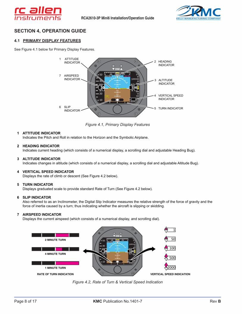
4.1 PRIMARY DISPLAY FEATURES
See Figure 4.1 below for Primary Display Features.
1 ATTITUDE INDICATOR Indicates the Pitch and Roll in relation to the Horizon and the Symbolic Airplane.
2 HEADING INDICATOR Indicates current heading (which consists of a numerical display, a scrolling dial and adjustable Heading Bug).
3 ALTITUDE INDICATOR Indicates changes in altitude (which consists of a numerical display, a scrolling dial and adjustable Altitude Bug).
4 VERTICAL SPEED INDICATOR Displays the rate of climb or descent (See Figure 4.2 below).
5 TURN INDICATOR Displays graduated scale to provide standard Rate of Turn (See Figure 4.2 below).
6 SLIP INDICATOR Also referred to as an Inclinometer, the Digital Slip Indicator measures the relative strength of the force of gravity and the
force of inertia caused by a turn; thus indicating whether the aircraft is slipping or skidding.
7 AIRSPEED INDICATOR Displays the current airspeed (which consists of a numerical display, and scrolling dial).
4001
�
���
GND TRKMAG HDG075045 ���
20
20
10
10
50
40
20
10
��kt
ALT
ft
ft/min
�
DIM
2 HEADING INDICATOR
4 VERTICAL SPEED INDICATOR
5 TURN INDICATOR
3 ALTITUDE INDICATOR
7 AIRSPEED INDICATOR
1 ATTITUDE INDICATOR
6 SLIP INDICATOR
VERTICAL SPEED INDICATION
4 MINUTE TURN
1 MINUTE TURN
RATE OF TURN INDICATION
2 MINUTE TURN4001
�
���
MAG HDG075045 ���
20
20
10
10
50
40
20
10
��kt
ALT
ft
ft/min
�
DIM
2000
100
500
50
1

RCA2610-3P Mini6 Installation/Operation Guide
Page 9 of 17Rev B
KELLY MANUFACTURING COMPANY
KMC
KMC Publication No.1401-7
4.2 STATUS DISPLAYS
See Figure 4.3 below for typical Status display features.
1. MAGNETIC HEADING INDICATOR The Magnetic Heading Indicator (MAG HDG) will be visible when using the Magnetic Heading mode.
2. GROUND TRACK INDICATOR The Ground Track Indicator (GND TRK) will be visible when using the GPS Ground Track mode.
3. PITCH SYNC INDICATOR Indicates that the Pitch Synchronization feature is active when visible (See Section 4.4.2 Pitch Sync Activation).
4.3 PRE-FLIGHT PROCEDURES
Duringpre-flightprocedures,theinstrumentmustbeprovidedwithadequateelectricalpowerundernormalvibrationconditions(engine running). A red “X” appears across the screen indicating that the instrument is booting up. After the red “X” disappears, the instrument is fully functional and after 3 minutes, reaches its optimum performance level.
Check that the Battery Charge Status Indicator displays at least 50% charge to ensure a minimum of 30 minutes of operation in the event of a power failure.
NOTEOntail-draggeraircraft,theindicatorwillnotshowasleveluntilafterachievinglevelflight.Noadjustmentarenecessarywhenlevelflightisachieved.
Figure 4.3, Status Displays
4001
�
���
GND TRKMAG HDG075045 ���
20
20
10
10
50
40
20
10
��kt
ALT
ft
ft/min
�
DIM2 GROUND
TRACK INDICATOR
3 PITCH SYNC INDICATOR
1 MAGNETIC HEADING INDICATOR

Page 10 of 17
RCA2610-3P Mini6 Installation/Operation Guide
Rev B
KELLY MANUFACTURING COMPANY
KMC
KMC Publication No.1401-7
4.4 IN FLIGHT PROCEDURES
4.4.1 FLIGHT MENU
To access the Flight Menu, Press the Flight Menu Selection Knob. The Flight Menu will appear on the lower portion of the screen. Rotate the Selection Knob to the desired setting and press the Selection Knob to select the highlighted menu option. Rotate the Selection Knob to the desired number or action and press Selection Knob to set. (See Figure 4.4 below).
NOTEThe Menu Style “Quick Access Mode” is an optional style for navigating the Flight Menu which moves through the selections by pressing the Selection Knob instead of turning the Selection Knob as in the “Normal Mode” (SeeSection3.1forhowtoconfigureMenuStyles).
HEADING Thisflightmenuoptionisusedtoinputthedesiredheading.ThisdesiredheadingnumberwillberepresentedontheHeadingIndi-cator tape by a yellow heading bug. This feature can also be quick accessed by rotating the Selection Knob.
ALT
2001BARO
30.06HDG
060ALT
2001BARO
30.06 060
SELECTHEADING100100
ALTITUDE Thisflightmenuoptionisusedtoinputthedesiredaltitude.ThisdesiredaltitudenumberwillberepresentedontheAltimeterIndi-cator tape by a yellow altimeter bug.
HDG
060BARO
30.06HDG
060ALT
2001BARO
30.06
SELECTALTITUDE
2001100100
BAROMETRIC PRESSURE ThisflightmenuoptionisusedtoinputtheBarometricpressure.
200ALT
1HDG
060ALT
2001BARO
30.06100 HDG
060 30.06100
BAROMETRICPRESS inHg
Figure 4.4 Flight Menu
4001
0
���
MAG HDG075045 ���
20
20
10
10
50
40
20
10
��kt
ALT
ft
ft/min
�
HDG
060ALT
2001BARO
30.06100
DIM
SELECTION KNOB
FLIGHT MENU

RCA2610-3P Mini6 Installation/Operation Guide
Page 11 of 17Rev B
KELLY MANUFACTURING COMPANY
KMC
KMC Publication No.1401-7
PITCH SYNCThisflightmenuoptionisusedtoinputanoffsetforthesymbolicairplaneifnecessary.
HDG TYPEMAG HDG
GND TRK
SYNC HDG TYPEMAG HDG
GND TRK
MAGNETICCOMP
MAGNETICCOMP
DONE+ 0°
PITCHSYNC
DONE+ 0°A “Quick Access” Pitch Sync is also available by simultaneously pressing both DIM buttons (See Section 4.4.2 Pitch Sync Activa-tion).Ifyoutypicallyflyina“nosedown”or“noseup”pitchattitude,youcanadjusttheAirplaneSymboltomatchtheHorizonLineon your instrument. The Pitch Synchronization (Pitch Sync) feature allows you to instantly sync the Airplane Symbol to the Horizon.
NOTEThisfeatureisnotnecessaryformostaircraftandistobeusedonlyinsituationswherenormalflightpitchisdeviated from 0 degrees.
HEADING TYPE The Mini6indicatorofferstwoHeadingIndicatortypes–Magnetic Heading and Ground Track (using GPS data). The green blinking light next to the “GND TRK” Heading Type option indicates that the Mini6 is receiving GPS data. This Flight Menu option is used to select between the two Heading Types.
SYNC
+ 0°MAGNETICCOMP
DONE
SYNC HDG TYPEMAG HDG
MAGNETICCOMP
DONE+ 0°
HEADINGTYPEMAG HDGGND TRK
MAGNETIC COMPENSATION ThisflightmenuoptionisusedtoperformtheMagnetic Compensation procedure.
MAG HDG
GND TRK
HDG TYPEMAG HDG
GND TRK
MAGNETICCOMP SYNCSYNC HDG TYPE
DONE
MAGNETICCOMPENSATION
STARTEXIT
+ 0° + 0°To compensate the instrument to eliminate the magnetic interference from the aircraft do the following:
1. After the Mini6 has been on for at least 3 minutes and the aircraftisinflight, Select Magnetic Comp -> “Start” from the flightmenu.“Gathering Mag Data” is shown on the display. This operation resets any previous compensation and the instrument begins to gather data for 10 minutes to perform the magnetic compensation.
2. During the 10 minutes the instrument is gathering data, perform two 360 degree turns to the right and two 360 deg turns to the left.
3. When the 10 minutes time is over, the instrument will show the message “Mag Data SAVED“
4. Turntheinstrumentoffandon.Themessagewilldisappearandtheinstrumentiscalibratedforthemagneticfieldoftheaircraft (hard iron correction).
NOTE Magnetic Comp will not be available until after the instrument has been turned on for at least 3 minutes.
During the calibration procedure, the instrument could behave erratically due to the calibration process.
EXIT MENUAfter making selections, rotate the Selection Knob all of the way to the right to the red “X” and press Selection Knob to leave the menu. The menu will also auto-close if no setting is selected.

Page 12 of 17
RCA2610-3P Mini6 Installation/Operation Guide
Rev B
KELLY MANUFACTURING COMPANY
KMC
KMC Publication No.1401-7
4.4.3 DIMMER
On startup, the Mini6 defaults at its maximum brightness. You may adjust the screen brightness at any time with the DIMMER PUSH BUTTONS (DIM). The NVIS Mini6 (P/N 102-0403-15-18) however, will revert to it’s last used brightness setting.
PressandholdtheDIM(▼)orBRIGHTEN(▲)PUSHBUTTONSuntilyoureachthedesiredsettingandrelease,ortapeachbut-tonforincrementalsteps(Seefigure4.6Dimmer Controls).
WARNING
If you press both buttons simultaneously, you will turn the PITCH SYNC feature on (as shown by the PITCH SYNC‘ON’INDICATOR).PressbothbuttonsagaintoturnthePITCHSYNCoffifitisnotneeded.RefertoSection 4.4.2 for more information on the PITCH SYNC feature.
Figure 4.5, Pitch Sync
4.4.2 PITCH SYNC ACTIVATION
Pitch Syncisusedtooffsetthesymbolicairplaneifnecessary.Onceyouhaveachievedthedesiredflyingpitch,activatethePitch Sync feature by pressing BOTH PUSH BUTTONS simultaneously. This synchronizes the Airplane Symbol to the Horizon Line. The Sync ‘On’ indicator will display “SYNC” when the Pitch Syncisactivated(seefigure4.5Pitch Sync).
PITCH SYNC DE-ACTIVATIONTo return to True Pitch, press BOTH PUSH BUTTONS simultaneously. This moves the Airplane Symbol back to True Pitch Indication and the Sync ‘On’ indicator will disappear. EXAMPLE:IntheexampleshowninFigure4.5,Theaircraftisflyinglevelata10degreenosedownpitchwiththePitch Sync on. The Sync “On” Indicator is being displayed. The Airplane Symbol is shown aligned with the Horizon Line at 0 degrees on the Pitch Dial.
4001
�
���
MAG HDG075045 ���
10
30
20
10
50
40
20
10
��kt
ALT
ft
ft/min
�
DIM
PITCH SYNCINDICATION
PUSHBUTTONS
SYNC “ON”INDICATOR

RCA2610-3P Mini6 Installation/Operation Guide
Page 13 of 17Rev B
KELLY MANUFACTURING COMPANY
KMC
KMC Publication No.1401-7
4.5 FLIGHT LIMITATIONS
TherearenoflightlimitationstotheMini6 Series Attitude Indicator. The instrument will operate in a full 360 degrees of turn and may be used in light aerobatic type maneuvers.
Extreme rotation speeds may cause the instrument to display a warning message to indicate to the pilot that the instrument may be operatingoutsidetheaccuracylimitsdefinedbytheTSO.Thismessageisdisplayedwhenthefullscaleoftheinstrumentsensorsis being exceeded and should go away within 3 to 10 seconds. Neither the display of the warning message, nor the extreme rotationspeedsthemselves,negativelyaffecttheinstrumentsoitisnotnecessarytoservicetheinstrumentintherareinstancethat the warning message is observed.
NOTEThis article meets the minimum performance and quality control standards required by a Technical Standard Order (TSO). Installation of this article requires separate approval.
4.6 EMERGENCY PROCEDURES
In the rare event that your Mini6 does not reset itself, you will need to pull power to the unit and reset the circuit breaker. This will restarttheunitandyoucancontinueonwithoutdamagetotheunit.Youdonotneedtobeflyinglevelwhiletheunitresets.
LOW VOLTAGE:In a low voltage situation, the Mini6 will show a “Low Voltage” warning notice at the bottom of the screen. This notice will appear when the voltage goes below 11 volts. This notice will also indicate the amount of voltage the instrument is receiving. At 5 volts, a warning will appear across the screen indicating that the instrument is not receiving enough power and will automatically switch to battery backup power.
Figure 4.6, Dimmer Controls
4001
�
���
MAG HDG075045 ���
20
20
10
10
50
40
20
10
��kt
ALT
ft
ft/min
�
DIM
DIM BRIGHTEN

Page 14 of 17
RCA2610-3P Mini6 Installation/Operation Guide
Rev B
KELLY MANUFACTURING COMPANY
KMC
KMC Publication No.1401-7
4.7 BATTERY BACKUP
The Mini6 is equipped with a lithium battery that will automatically provide an hour of battery power in the event of a power loss. If battery power is required for more than an hour, it is recommended to reduce the screen brightness to 80% once the power loss occurs. This will nearly triple the battery power time.
Associated battery messages:
“60 Second Countdown”indicatespowerlosswhilestationary(asdetectedthroughairspeed)-(normalshutoff).
“Power Loss Switching to Battery”indicatesapowerlossduringflight(asdetectedthroughairspeed).
“Batt Pwr” indicates when the unit is operating in the Battery Mode.(To shutdown Battery Mode, simultaneously press and hold both “Dim” buttons).
“Chk Batt” indicates that either the battery failed the capacity test or is inoperable (See Section 4.8 Battery Replacement).
4.8 BATTERY REPLACEMENT
When the “Chk Batt” warning appears on the screen, it indicates that either the battery failed the capacity test, there was a prob-lem with the capacity test, or the battery is inoperable. Before replacing the battery, perform another capacity test by completing steps 6 through 9 to re-test the battery. If this does not clear the “Chk Batt” message, the battery must then be replaced as soon as possible. (See Figure 4.8 below) (replace battery with P/N 635-0002-01 Battery Assy).
To replace the battery:
1. RemoveBatteryCoverscrews.(QTY:2)
2. Remove Battery Cover.
3. Disconnect Battery Assembly.
4. Connect new Battery Assembly.
5. Reinstall Battery Cover and screws.
6. Apply power and allow the instrument to run for at least 3 minutes until the Battery Charge Status icon reaches 100%.
7. Adjust DIM buttons so that the screen brightness is at 100%.
8. Once the Battery Charge Status icon reaches 100%, disconnect power to the instrument and allow the instrument to complete the 60 second countdown.
9. Reapply power and check that no battery related messages appear.
Figure 4.7, Battery Replacement
BATTERY
BATTERY CASE
SCREWS

RCA2610-3P Mini6 Installation/Operation Guide
Page 15 of 17Rev B
KELLY MANUFACTURING COMPANY
KMC
KMC Publication No.1401-7
SECTION 5, GENERAL INFORMATION
5.1 INSTRUMENT CARE
The most easily damaged part of your instrument is the screen. Special care should be taken when cleaning the screen to prevent scratches and other damage. Avoid touching the screen at all times.
To clean light spots and dust, use a soft, lint free cotton cloth slightly moistened with distilled water.
You may also use cleaners approved for LCD TV’s and laptop computer screens.
Always apply the cleaner to the cloth and not the screen.
-CAUTION- ● Do Not use paper towels, facial tissue or napkins. These products are made from recycled paper and
may contain metals and wood chips that will scratch the screen.
● Do Not use acetone, alcohol or cleaners containing ammonia.
By avoiding all screen contact and by using proper cleaning methods, the user will be rewarded with many years of service.
5.2 FREQUENTLY ASKED QUESTIONS
How long should my Digital Instrument last?There isn’t a good answer for this question. There are no moving parts in the Mini6 so there isn’t anything to wear out. The Mini6 should give hundreds of hours of trouble free operation.
At what voltage level will my Digital Instrument become unreliable?Unlike mechanical horizons, the Mini6doesn’thavearotorthatisaffectedbyvoltage.The Mini6 will be reliable from 9 to 32VDC. In the event of a power loss, the Battery Backup power will be available. My instrument is showing a climb/dive, what can I do?You can check your aircraft owner’s manual or contact the aircraft manufacturer to determine if your aircraft’s instrument panel istilted(pitchedforeandaft).Thetiltangleisanydeviationfromverticalofyourinstrumentpanelinlevelflight.Yourinstrumentneeds to be calibrated to compensate for this angle.
Myinstrumentisshowingaturninlevelflight,whatcanIdo?It is very important to have the instrument level (left and right) in your panel. If the instrument is not level, it will show a turn when in levelflight.Toleveltheinstrument,refertoinstallationSection2.4.6.
How do I get my instrument repaired?For any overhaul or repair questions you can contact Kelly Manufacturing Company. Our Service Center can repair or refurbish any RC Allen instrument. The only thing really required is information. You can send us your instrument with a letter giving us your name, return shipping address, phone number and a brief description of what is wrong with the instrument or download a form from theSupportpageonourwebsiteat:kellymfg.com/support.html.
Emailusformoreinformation:[email protected].
Or,VisitourWebSite:kellymfg.com
KELLYMFG.COM
KMC
VISIT US AT:

Page 16 of 17
RCA2610-3P Mini6 Installation/Operation Guide
Rev B
KELLY MANUFACTURING COMPANY
KMC
KMC Publication No.1401-7
APPENDIX AEnvironmental Qualification form
Environmental Qualification: DO-160G Environmental Qualification Form
NOMENCLATURE: ELECTRIC DIGITAL HORIZON
MODEL NUMBER: RCA2610-series TSO NUMBER: C4c & C113a
MANUFACTURERS SPECIFICATIONS: STP 1501 Rev. A (12/20/2016)
MANUFACTURER: Kelly Manufacturing Company
ADDRESS: 555 S. Topeka, Wichita, KS 67202
REVISION & CHANGE NUMBER OF DO-160: Rev. G DATES TESTED: 4/26/16 thru 5/24/16
CONDITIONS SECTION DESCRIPTION OF TESTS CONDUCTED Temperature and Altitude Low Temperature High Temperature Altitude
4.0 4.5.1 4.5.2 & 4.5.3 4.6.1
Equipment tested to Category D1
Temperature Variation 5.0 Equipment tested to Category C Humidity 6.0 Equipment tested to Category A Operational Shocks and Crash Safety 7.0 Equipment tested to Category B Vibration 8.0 Equipment tested to Category U2 curve F & F1 Explosive Atmosphere 9.0 Equipment identified as category X, no test performed Waterproofness 10.0 Equipment identified as category X, no test performed Fluids Susceptibility 11.0 Equipment identified as category X, no test performed Sand and Dust 12.0 Equipment identified as category X, no test performed Fungus 13.0 Equipment identified as category X, no test performed Salt Fog Test 14.0 Equipment identified as category X, no test performed Magnetic Effect 15.0 Equipment tested to Category Z Power Input 16.0 Equipment tested to Category BRX Voltage Spike 17.0 Equipment tested to Category A Audio Frequency Susceptibility 18.0 Equipment tested to Category Z Induced Signal Susceptibility 19.0 Equipment tested to Category ZC Radio Frequency Susceptibility (Radiated and Conducted)
20.0 Equipment tested for Conducted Susceptibility to Category W Equipment tested for Radiated Susceptibility to Category F
Emissions of Radio Frequency Energy 21.0 Equipment tested to Category M
Lightning Induced Transient Susceptibility
22.0
Equipment tested to Pin Injection Test: Waveform set B, Level 3 Cable Bundle Test: Waveform set H, Level 3 Multiple Burst: Level 3 [B3H33]
Lightning Direct Effects 23.0 Equipment identified as category X, no test performed Icing 24.0 Equipment identified as category X, no test performed Electrostatic Discharge 25.0 Equipment tested to Category A Fire, Flammability 26.0 Equipment identified as category X, no test performed
REMARKS
In the power input test, equipment was tested to subparagraph 16.5.1.4 b, requirement for equipment with digital circuits
Equipment also tested to (and passed) section 20, SW/CW radiated susceptibility @100V/m from 100MHz to 1GHz

RCA2610-3P Mini6 Installation/Operation Guide
Page 17 of 17Rev B
KELLY MANUFACTURING COMPANY
KMC
KMC Publication No.1401-7
APPENDIX BInstructions for Continued Airworthiness Page 1
Instructions for Continued Airworthiness
Document Number: ICA21.007
Revision: A
May 13, 2021 Page 1 of 2
Equipment/Model Number: RCA2610-3P-Mini6 Equipment Description: Multifunctional Indicator 1. Description This document describes the necessary maintenance requirements and instructions necessary to ensure the continued airworthiness of aircraft/rotorcraft with the RCA2610-3P-Mini6 Multifunctional Indicator installed.
2. Operation Operating Instructions for the RCA2610-3P-Mini6 are detailed in the following document: Kelly Manufacturing Company Operation/Installation Guide (Publication No. 1401-7)
3. Equipment Certifications FAA TSO-C4c FAA TSO-C113a FAA TSO-C3e FAA TSO-C6e FAA TSO-C2d FAA TSO-C10c FAA TSO-C8e
AS396B AS8034B AS8004 AS8013A AS8019 AS8009C AS8016A
RTCA DO-160G RTCA DO-178B Lv. C RTCA DO-347
3. Servicing No scheduled service required
4. Maintenance Instructions Every 12 months: Check that the Mini6 Indicator is responding properly and operating within the guidelines detailed in Kelly Manufacturing Company Publication No. 1401-7. Also verify the following No warning/error message exists on the display. No drop off or inconsistency in display brightness.
Every 24 months: 1) Check functional indication accuracy Indication accuracy of Attitude and Heading can be verified in flight test using the following procedure: After take-off and before IFR situations perform two standard turns in opposite
directions. Return aircraft to level flight/cruising speeds for a minimum of 2 minutes. Verify the Mini6 indicates level in pitch and roll within two degrees and indicates
heading (when applicable) within 2 degrees. Service is required if the Mini6 Indicator does not pass this flight test. Instrument service can be performed at Kelly Manufacturing Company [email protected]
2) Calibrate Air Data Perform calibration procedure for air data functions per section 3.2 of Publication 1401-7.

Page 18 of 17
RCA2610-3P Mini6 Installation/Operation Guide
Rev B
KELLY MANUFACTURING COMPANY
KMC
KMC Publication No.1401-7
APPENDIX BInstructions for Continued Airworthiness Page 2
Instructions for Continued Airworthiness
Document Number: ICA21.007
Revision: A
May 13, 2021 Page 2 of 2
3) Confirm World Mag Model Contact Kelly Manufacturing Company with serial number of the unit to determine if update to the World Magnetic Module is required for the GPS of the unit. Every 36 months: Replace Battery Assembly (635-0002-01) on applicable units equipped with a battery backup option. Reference section 4.11 of Publication 1401-7. Contact Kelly Manufacturing Company for availability [email protected] Airworthiness Limitations There are no airworthiness limitations for the RCA2610 Reference Kelly Manufacturing Company Publication 1401-7 for operating ranges and indication limitations.
Notes
Revision History Revision Date Detail A 5/13/2021 Initial Release


KMC PUBLICATION NO. 1401-7
KELLY MANUFACTURING COMPANY555 S. TOPEKA
WICHITA, KANSAS 67202WWW.KELLYMFG.COM