Embed Size (px)
Citation preview
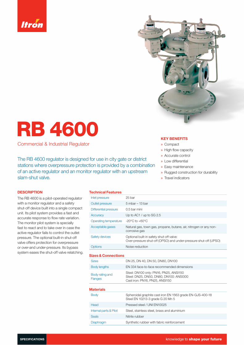
RB 4600Commercial & Industrial Regulator
The RB 4600 regulator is designed for use in city gate or district stations where overpressure protection is provided by a combination of an active regulator and an monitor regulator with an upstream slam-shut valve.
KEY BENEFITS
» Compact
» High flow capacity
» Accurate control
» Low differential
» Easy maintenance
» Rugged construction for durability
» Travel indicators
DESCRIPTION
The RB 4600 is a pilot-operated regulator with a monitor regulator and a safety shut-off device built into a single compact unit. Its pilot system provides a fast and accurate response to flow rate variation. The monitor pilot system is specially fast to react and to take over in case the active regulator fails to control the outlet pressure. The optional built-in shut-off valve offers protection for overpressure or over-and under-pressure. Its bypass system eases the shut-off valve relatching.
Technical FeaturesInlet pressure 25 bar
Outlet pressure 5 mbar – 13 bar
Differential pressure 0.5 bar mini
Accuracy Up to AC1 / up to SG 2.5
Operating temperature -20°C to +60°C
Acceptable gases Natural gas, town gas, propane, butane, air, nitrogen or any non-corrosive gas
Safety devices Optional built-in safety shut-off valve: Over-pressure shut-off (OPSO) and under-pressure shut-off (UPSO)
Options Noise reduction
Sizes & ConnectionsSizes DN 25, DN 40, DN 50, DN80, DN100
Body lengths EN 334 face-to-face recommended dimensions
Body rating and Flanges
Steel: DN100 only: PN16, PN25, ANSI150Steel: DN25, DN50, DN80, DN100: ANSI300Cast iron: PN16, PN25, ANSI150
MaterialsBody Spheroidal graphite cast iron EN 1563 grade EN-GJS-400-18
Steel EN 10213-3 grade G 20 Mn 5
Head Pressed steel / UNI EN10025
Internal parts & Pilot Steel, stainless steel, brass and aluminium
Seals Nitrile rubber
Diaphragm Synthetic rubber with fabric reinforcement
SPECIFICATIONS knowledge to shape your future
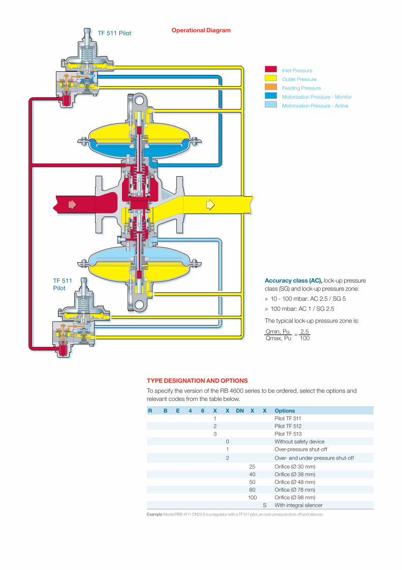
TF 511 Pilot
TF 511Pilot
Inlet Pressure
Outlet Pressure
Feeding Pressure
Motorization Pressure - Monitor
Motorization Pressure - Active
Accuracy class (AC), lock-up pressure class (SG) and lock-up pressure zone:
» 10 - 100 mbar: AC 2.5 / SG 5
» 100 mbar: AC 1 / SG 2.5
The typical lock-up pressure zone is:
Qmin, Pu 2.5Qmax, Pu 100
=
TYPE DESIGNATION AND OPTIONS
To specify the version of the RB 4600 series to be ordered, select the options and relevant codes from the table below.
R B E 4 6 X X DN X X Options1 Pilot TF 5112 Pilot TF 512 3 Pilot TF 513
0 Without safety device1 Over-pressure shut-off
2 Over- and under-pressure shut-off
25 Orifice (Ø 30 mm)40 Orifice (Ø 38 mm)50 Orifice (Ø 48 mm)80 Orifice (Ø 78 mm)100 Orifice (Ø 98 mm)
S With integral silencer
Example: Model RBE 4711 DN25 S is a regulator with a TF 511 pilot, an over-pressure shut-off and silencer.
Operational Diagram
Standard conditions:
- Absolute pressure of 1.013 bar- Temperature of 15°C
Correction factor for non-natural gas applications:
The flow rates are indicated for a 0.6 specific gravity gas.To determine the volumetric flow rate for gases other than natural gas, multiply or calculate the values in the capacity tables using the sizing equations with a correction factor.The table below lists correction factors for some common gases:
Gas type Specific Correction gravity factor
Air 1.00 0.77
Butane 2.01 0.55
Carbon dioxide (dry) 1.52 0.63
Carbon monoxide (dry) 0.97 0.79
Natural gas 0.60 1.00
Nitrogen 0.97 0.79
Propane 1.53 0.63
Propane-Air mix 1.20 0.71
Specific gravity or relative density (air = 1, non-dimensional value)
Use the following formula to calculate the correction factor for gases not listed above. In the formula, d is the specific gravity of the gas.
Correction factor = 0.6d
where:
Q = volumetric flow rate in m3/h at standard conditionsPu = absolute inlet pressure in barPd = absolute outlet pressure in barSin = angle in degrees
Outlet Pressure Range
Pilot Type
Spring Code
Spring Characteristic Spring Ranged
(mm)De
(mm)Lo
(mm)Lt mbar bar
TF 511 20565125 2.5 35 50 6 5 - 25TF 511 20565126 3 35 50 6 20 - 68TF 511 20565127 3.5 35 50 6 40 - 140TF 511 20565128 4 35 50 6 80 - 280TF 512 20565128 4 35 50 6 0.1 - 0.6TF 512 20565129 4.5 35 50 6 0.2 - 1TF 513 20565132 3.5 35 60 6.5 0.25 - 1.3TF 513 20565133 4 35 60 6.5 0.5 - 2.5TF 513 20565131 5 35 60 6.5 1.5 - 5.5TF 513 20565134 6 35 60 6.5 4 - 13
The TF 500 series pilot system includes a built-in pre-regulator which is loaded by the oulet pressure to provide the pilot with a feeding pressure 500 mbar above outlet pressure.
The pre-regulator is fitted with a separate filter.
PILOT SYSTEM
The RB 4600 regulator includes 2 pilot operated regulators, each of them being controlled by a pilot system serie TF 500 as follows:
TF 5 1 X Options
1 Low pressure: 5 - 280 mbar
2 Medium pressure: 0.1 - 1 bar
3 High pressure: 0.25 - 13 bar
Remote Control
The TF 512-PL series pilot system is designed for applications where the regulator set point must be controlled remotely, such as leak management systems, process control applications, etc. In the TF 512-PL series pilot system, the pilot setting element, which is a spring in conventional pilots, is replaced by an external loading pressure. See separate Technical Information Bulletin
Spring characteristics:
d: wire diameter De: external diameter
Lo: heightLt: no. of spires
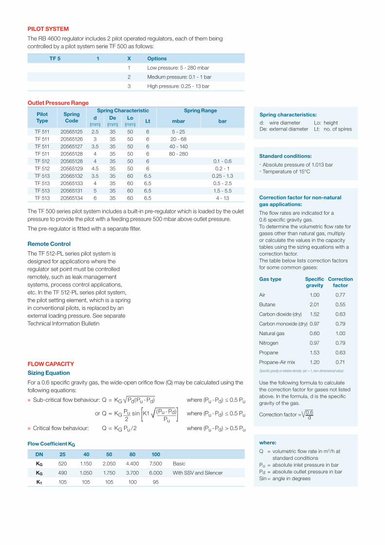
FLOW CAPACITY
Sizing Equation
For a 0.6 specific gravity gas, the wide-open orifice flow (Q) may be calculated using the following equations:
» Sub-critical flow behaviour: Q = KG √ Pd(Pu - Pd) where (Pu - Pd) ≤ 0.5 Pu
or Q = KG Pu sin [K1 √ (Pu - Pd)] where (Pu - Pd) ≤ 0.5 Pu 2 Pu
» Critical flow behaviour: Q = KG Pu / 2 where (Pu - Pd) > 0.5 Pu
Flow Coefficient KG
DN 25 40 50 80 100
KG 520 1.150 2.050 4.400 7.500 Basic
KG 490 1.050 1.750 3.700 6.000 With SSV and Silencer
K1 105 105 105 100 95
SET RANGEOver-Pressure Shut-Off Springs (OPSO)
Spring CodeSpring Characteristic
ColourSpring Range
d(mm)
De(mm)
Lo(mm)
Lt8611/12(Ø 150)
8621/22(Ø 150/TR)
8631/ 8632(Ø 90)
8641/ 8642(Ø 90/TR)
20565233 2.2 35 60 7 Yellow 28 - 65 mbar • • •
20565234 2.5 35 60 7 Red 45 - 100 mbar • • •
20565330 2.7 35 60 7 White 80 - 140 mbar • • •
20565331 3 35 60 7 Blue 100 - 240 mbar • 0.60 - 0.90 bar •
20565332 3.5 35 60 7 Orange 190 - 350 mbar 0.55 - 0.90 bar 0.90 - 1.40 bar •
20565333 4 35 60 7 Brown 350 - 700 mbar 0.90 - 1.70 bar 1.40 - 2.40 bar 2.30 - 4.10 bar
20565334 4.2 35 60 7 Green 450 - 800 mbar 1.50 - 2.00 bar 2.00 - 3.10 bar 3.10 - 5.00 bar
20565430 4.5 35 60 7 Black 600 - 1000 mbar 1.70 - 2.30 bar 2.50 - 3.90 bar 3.80 - 6.00 bar
20565431 5 35 60 7 Grey 950 - 1300 mbar 2.30 - 3.00 bar 3.90 - 4.60 bar 5.70 - 7.50 bar
20565432 5.5 35 60 7 Yellow • • 4.60 - 6.30 bar 7.50 - 10.00 bar
20565134 6 35 60 7 Red • • 6.30 - 10.80 bar 10.00 - 15.00 bar
Under-Pressure Shut-Off Springs (UPSO)
Spring CodeSpring Characteristic
ColourSpring Range
d(mm)
De(mm)Lo
(mm)Lt
8611/12(Ø 150)
8621/22(Ø 150/TR)
8631/ 8632(Ø 90)
8641/ 8642(Ø 90/TR)
20561124 1.2 15 40 10 White 5 - 18 mbar • • •
20561221 1.5 15 40 10 Blue 10 - 55 mbar • • •
20561222 1.7 15 40 10 Orange 30 - 75 mbar 0.11 - 0.29 bar 0.23 - 0.37 bar 0.32 - 0.63 bar
20561223 2 15 40 10 Brown 60 - 150 mbar 0.16 - 0.49 bar 0.26 - 0.66 bar 0.42 - 1.10 bar
20561224 2.5 15 40 10 Green 100 - 250 mbar 0.21 - 0.74 bar 0.32 - 1.00 bar 0.60 - 2.20 bar
20561321 2.8 15 35 7 • • • •2.20 - 3.30 barmin ∆p = 1 bar
Type Designation and Options
SSV 86 X X Versions
1 ø 150
2 ø 150/TR
3 ø 90
4 ø 90/TR
1 OPSO
2 OPSO + UPSO
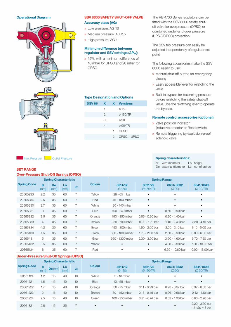
Operational Diagram SSV 8600 SAFETY SHUT-OFF VALVE
Accuracy class (AG)
» Low pressure: AG 10
» Medium pressure: AG 2.5
» High pressure: AG 1
Minimum difference between regulator and SSV settings (∆Pw):
» 15%, with a minimum difference of 10 mbar for UPSO and 20 mbar for OPSO.
The RB 4700 Series regulators can be fitted with the SSV 8600 safety shut-off valve for overpressure (OPSO) or combined under-and-over pressure (UPSO/OPSO) protection.
The SSV trip pressure can easily be adjusted independently of regulator set point.
The following accessories make the SSV 8600 easier to use:
» Manual shut-off button for emergency closing
» Easily accessible lever for relatching the valve
» Built-in bypass for balancing pressure before relatching the safety shut-off valve. Use the relatching lever to operate the bypass.
Remote control accessories (optional):
» Valve position indicator (inductive detector or Reed switch)
» Remote triggering by explosion-proof solenoid valve
Spring characteristics:
d: wire diameter De: external diameter
Lo: heightLt: no. of spires
Inlet Pressure Outlet Pressure
Maximum Inlet Pressure
For higher inlet pressure, the SSV 8500 is fitted with heavier closing spring which gives a positive lock-up even in case of high pressure differential across the valve. The following table indicates the maximum inlet pressure for both options.
DN 25 40 50 80
Standard 6 bar 6 bar 6 bar 6 bar
Heavy duty 16 bar 16 bar 16 bar 6 bar
Type Designation and Options
SSV 85 X X Versions
1 Ø 120 or 150
2 Ø 90
3 Ø 90/TR
1 OPSO
2 OPSO + UPSO
SET RANGE
Over Pressure Shut-off Springs (OPSO)
Spring Code Spring Characteristic Spring Range
d(mm)
De(mm)
Lo(mm)
Lt8511/12(Ø 150)
8521/22(Ø 90)
8531/132(Ø 90 TR)
20565225 2 35 50 6 25 - 49 mbar 0.13 - 0.24 bar •20565125 2.5 35 50 6 44 - 120 mbar 0.20 - 0.46 bar •20565126 3 35 50 6 95 - 200 mbar 0.42 - 0.90 bar •20565127 3.5 35 50 6 200 - 350 mbar 0.83 - 1.84 bar 1.25 - 3.00 bar20565128 4 35 50 6 • 1.32 - 2.25 bar 2.30 - 4.20 bar20565129 4.5 35 50 6 • 2.28 - 3.15 bar 3.60 - 5.60 bar
Under Pressure Shut-off Springs (UPSO)
Spring Code Spring Characteristic Spring Range
d(mm)
De(mm)
Lo(mm)
Lt8511/12(Ø 150)
8521/22(Ø 90)
8531/132(Ø 90 TR)
20561022 1.2 15 35 7.75 9 - 19 mbar 0.06 - 0.10 bar •
20560815 1.3 15 35 8 14 - 30 mbar 0.10 - 0.25 bar 0.15 - 0.40 bar
20561023 1.5 15 35 7.75 28 - 60 mbar 0.10 - 0.33 bar 0.30 - 0.60 bar20561024 1.8 15 35 7.5 60 - 100 mbar 0.30 - 0.70 bar 0.58 - 1.25 bar20561121 2 15 35 7.25 • 0.60 - 1.10 bar 1.20 - 1.70 bar20561122 2.5 15 35 7.25 • • 1.08 - 2.50 bar
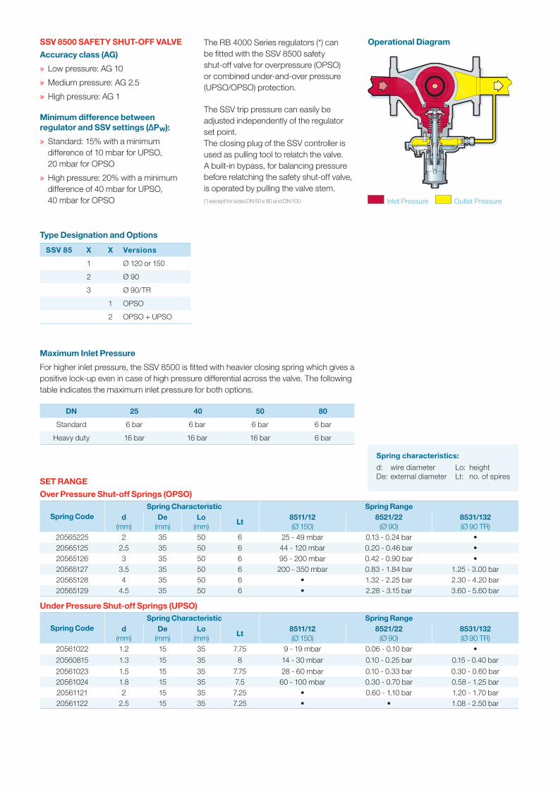
Operational DiagramSSV 8500 SAFETY SHUT-OFF VALVE
Accuracy class (AG)
» Low pressure: AG 10
» Medium pressure: AG 2.5
» High pressure: AG 1
Minimum difference between regulator and SSV settings (∆Pw):
» Standard: 15% with a minimum difference of 10 mbar for UPSO, 20 mbar for OPSO
» High pressure: 20% with a minimum difference of 40 mbar for UPSO, 40 mbar for OPSO
The RB 4000 Series regulators (*) can be fitted with the SSV 8500 safety shut-off valve for overpressure (OPSO) or combined under-and-over pressure (UPSO/OPSO) protection.
The SSV trip pressure can easily be adjusted independently of the regulator set point. The closing plug of the SSV controller is used as pulling tool to relatch the valve. A built-in bypass, for balancing pressure before relatching the safety shut-off valve, is operated by pulling the valve stem.(*) except for sizes DN 50 x 80 and DN 100.
Spring characteristics:
d: wire diameter De: external diameter
Lo: heightLt: no. of spires
Inlet Pressure Outlet Pressure
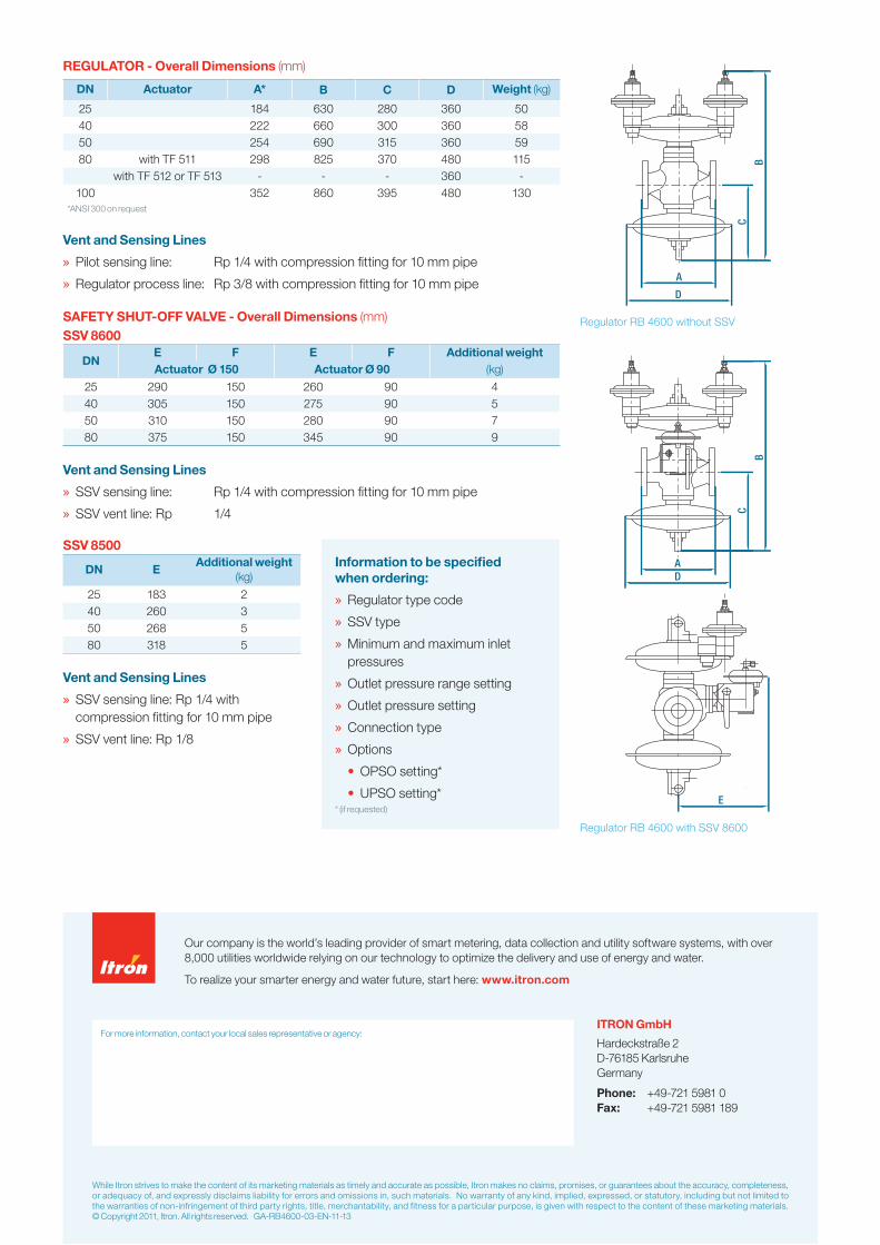
REGULATOR - Overall Dimensions (mm)
DN Actuator A* B C D Weight (kg)
25 184 630 280 360 5040 222 660 300 360 5850 254 690 315 360 5980 with TF 511 298 825 370 480 115
with TF 512 or TF 513 - - - 360 -100 352 860 395 480 130
*ANSI 300 on request
Vent and Sensing Lines
» Pilot sensing line: Rp 1/4 with compression fitting for 10 mm pipe
» Regulator process line: Rp 3/8 with compression fitting for 10 mm pipe
SAFETY SHUT-OFF VALVE - Overall Dimensions (mm)SSV 8600
DNE F E F Additional weightActuator Ø 150 Actuator Ø 90 (kg)
25 290 150 260 90 440 305 150 275 90 550 310 150 280 90 780 375 150 345 90 9
Vent and Sensing Lines
» SSV sensing line: Rp 1/4 with compression fitting for 10 mm pipe
» SSV vent line: Rp 1/4
SSV 8500
DN EAdditional weight
(kg)
25 183 240 260 350 268 580 318 5
Vent and Sensing Lines
» SSV sensing line: Rp 1/4 with compression fitting for 10 mm pipe
» SSV vent line: Rp 1/8
D
B
C
A
E
DA
C
B
Regulator RB 4600 without SSV
Regulator RB 4600 with SSV 8600
Information to be specified when ordering:
» Regulator type code
» SSV type
» Minimum and maximum inlet pressures
» Outlet pressure range setting
» Outlet pressure setting
» Connection type
» Options
• OPSO setting*
• UPSO setting* * (if requested)
While Itron strives to make the content of its marketing materials as timely and accurate as possible, Itron makes no claims, promises, or guarantees about the accuracy, completeness, or adequacy of, and expressly disclaims liability for errors and omissions in, such materials. No warranty of any kind, implied, expressed, or statutory, including but not limited to the warranties of non-infringement of third party rights, title, merchantability, and fitness for a particular purpose, is given with respect to the content of these marketing materials. © Copyright 2011, Itron. All rights reserved. GA-RB4600-03-EN-11-13
Our company is the world’s leading provider of smart metering, data collection and utility software systems, with over 8,000 utilities worldwide relying on our technology to optimize the delivery and use of energy and water.
To realize your smarter energy and water future, start here: www.itron.com
ITRON GmbH
Hardeckstraße 2 D-76185 Karlsruhe Germany
Phone: +49-721 5981 0 Fax: +49-721 5981 189
For more information, contact your local sales representative or agency: