Embed Size (px)
Citation preview
RAV4 PRIME
RAV4 Plug-in Hybrid
Gasoline-Electric
Hybrid Synergy Drive
AXAP54 Series
Foreword
This guide was developed to educate and assist dismantlers in the safe handling of Toyota RAV4 PRIME,
RAV4 Plug-in Hybrid gasoline-electric hybrid vehicles. RAV4 PRIME, RAV4 Plug-in Hybrid
dismantling procedures are similar to other non-hybrid Toyota vehicles with the exception of the high
voltage electrical system. It is important to recognize and understand the high voltage electrical system
features and specifications of the Toyota RAV4 PRIME, RAV4 Plug-in Hybrid, as they may not be
familiar to dismantlers.
High voltage electricity powers the A/C compressor, electric motors, generator, and inverter/converter.
All other conventional automotive electrical devices such as the head lights, radio, and gauges are
powered from a separate 12 Volt auxiliary battery. Numerous safeguards have been designed into the
RAV4 PRIME, RAV4 Plug-in Hybrid to help ensure the high voltage, approximately 355.2 Volt, Lithium-
ion (Li-ion) Hybrid Vehicle (HV) battery pack is kept safe and secure in an accident.
The Lithium-ion battery pack contains sealed batteries that are similar to rechargeable batteries used in
some battery operated power tools and other consumer products. The electrolyte is absorbed in the cell
plates and will not normally leak out even if the battery is cracked. If the electrolyte is leaking, do not
touch any leaked liquid because it could be the organic electrolyte that contains carbonate ester-based.
If contact is unavoidable, wipe up the liquid using a cloth while wearing rubber gloves, goggles and an
organic solvent mask. Do not leave electrolyte-contaminated cloths unattended. Please contaminated
cloths in an appropriate airtight container and dispose of them according to local regulations.
High voltage cables, identifiable by orange insulation and connectors, are isolated from the metal chassis
of the vehicle.
Additional topics contained in the guide include:
• Toyota RAV4 PRIME, RAV4 Plug-in Hybrid identification.
• Major hybrid component locations and descriptions.
By following the information in this guide, dismantlers will be able to handle RAV4 PRIME, RAV4 Plug-
in Hybrid hybrid-electric vehicles as safely as the dismantling of a conventional gasoline engine
automobile.
© 2020 Toyota Motor Corporation All rights reserved. This book may not be reproduced or
copied, in whole or in part, without the written permission
of Toyota Motor Corporation.

Table of Contents
About the RAV4 PRIME, RAV4 Plug-in Hybrid ..................................................................................... 1
RAV4 PRIME, RAV4 Plug-in Hybrid Identification ............................................................................... 2
Exterior ......................................................................................................................................................... 3 Interior ........................................................................................................................................................... 4 Engine Compartment .................................................................................................................................... 5
Hybrid Component Locations & Descriptions ......................................................................................... 6
Specifications ................................................................................................................................................ 8
Hybrid Synergy Drive Operation .............................................................................................................. 9
Vehicle Operation .......................................................................................................................................... 9
Hybrid Vehicle (HV) Battery Pack and Auxiliary Battery.................................................................... 10
HV Battery Pack .......................................................................................................................................... 10 Components Powered by the HV Battery Pack........................................................................................... 10 HV Battery Pack Recycling ......................................................................................................................... 11 Auxiliary Battery .......................................................................................................................................... 11
High Voltage Safety .................................................................................................................................. 12
High Voltage Safety System ....................................................................................................................... 12 Service Plug Grip ........................................................................................................................................ 13
Precaution to be observed when dismantling the vehicle ...................................................................... 14
Necessary Items ......................................................................................................................................... 14
Spills .......................................................................................................................................................... 15
Dismantling the vehicle ............................................................................................................................ 16
Removal of HV battery ............................................................................................................................ 21

1
About the RAV4 PRIME, RAV4 Plug-in Hybrid
The RAV4 PRIME, RAV4 Plug-in Hybrid contains a gasoline engine, an electric motor,
and a developed large capacity Li-ion battery. It is the Toyota hybrid that allows the
HV battery to be plugged-in and charged by an external power source. The two hybrid power sources are stored on board the vehicle:
1. Gasoline stored in the fuel tank for the gasoline engine.
2. Electricity stored in a large capacity externally chargeable high voltage Hybrid
Vehicle (HV) battery assembly for the electric motor.
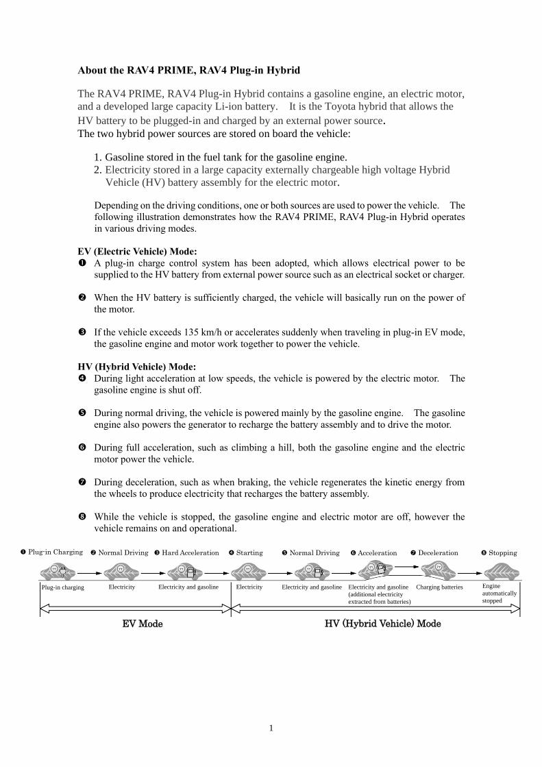
Depending on the driving conditions, one or both sources are used to power the vehicle. The
following illustration demonstrates how the RAV4 PRIME, RAV4 Plug-in Hybrid operates
in various driving modes.
EV (Electric Vehicle) Mode:
A plug-in charge control system has been adopted, which allows electrical power to be
supplied to the HV battery from external power source such as an electrical socket or charger.
When the HV battery is sufficiently charged, the vehicle will basically run on the power of
the motor.
If the vehicle exceeds 135 km/h or accelerates suddenly when traveling in plug-in EV mode,
the gasoline engine and motor work together to power the vehicle.
HV (Hybrid Vehicle) Mode:
During light acceleration at low speeds, the vehicle is powered by the electric motor. The
gasoline engine is shut off.
During normal driving, the vehicle is powered mainly by the gasoline engine. The gasoline
engine also powers the generator to recharge the battery assembly and to drive the motor.
During full acceleration, such as climbing a hill, both the gasoline engine and the electric
motor power the vehicle.
During deceleration, such as when braking, the vehicle regenerates the kinetic energy from
the wheels to produce electricity that recharges the battery assembly.
While the vehicle is stopped, the gasoline engine and electric motor are off, however the
vehicle remains on and operational.
Hard Acceleration Normal Driving
EV Mode HV (Hybrid Vehicle) Mode
Plug-in Charging
Plug-in charging Electricity Electricity and gasoline Electricity Electricity and gasoline Electricity and gasoline
(additional electricity
extracted from batteries)
Charging batteries Engine
automatically
stopped
Starting Normal Driving Acceleration Deceleration Stopping
2
RAV4 PRIME, RAV4 Plug-in Hybrid Identification
In appearance, the 2020 model year RAV4 PRIME, RAV4 Plug-in Hybrid is nearly
identical to the conventional, non-hybrid Toyota RAV4. The RAV4 PRIME, RAV4
Plug-in Hybrid is a 5-door wagon. Exterior, interior, and engine compartment
illustrations are provided to assist in identification.
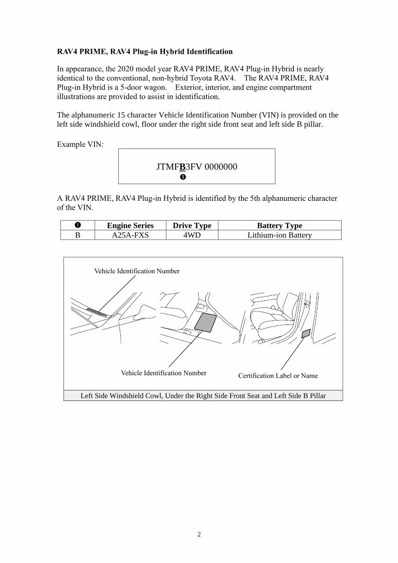
The alphanumeric 15 character Vehicle Identification Number (VIN) is provided on the
left side windshield cowl, floor under the right side front seat and left side B pillar.
Example VIN:
JTMFB3FV 0000000
A RAV4 PRIME, RAV4 Plug-in Hybrid is identified by the 5th alphanumeric character
of the VIN.
Engine Series Drive Type Battery Type
B A25A-FXS 4WD Lithium-ion Battery
Left Side Windshield Cowl, Under the Right Side Front Seat and Left Side B Pillar
Vehicle Identification Number
Certification Label or Name
Label
Vehicle Identification Number
3
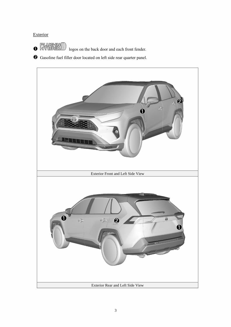
Exterior
logos on the back door and each front fender.
Gasoline fuel filler door located on left side rear quarter panel.
Exterior Front and Left Side View
Exterior Rear and Left Side View
4
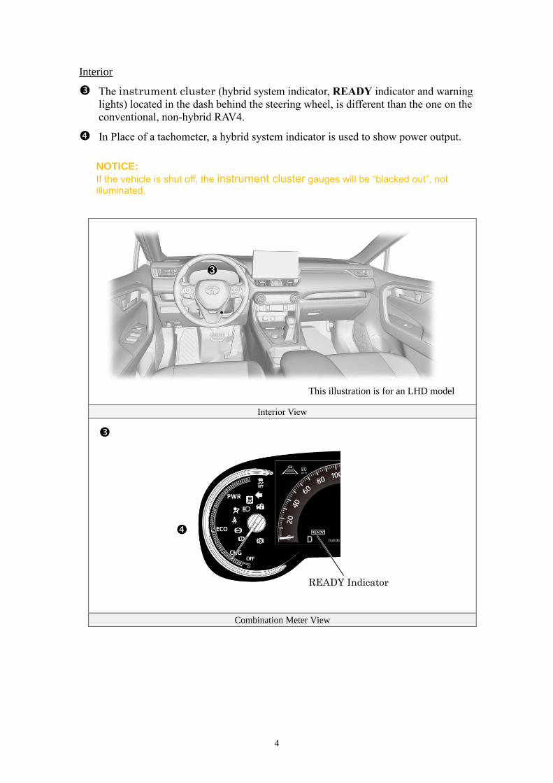
Interior
The instrument cluster (hybrid system indicator, READY indicator and warning
lights) located in the dash behind the steering wheel, is different than the one on the
conventional, non-hybrid RAV4.
In Place of a tachometer, a hybrid system indicator is used to show power output.
NOTICE:
If the vehicle is shut off, the instrument cluster gauges will be “blacked out”, not illuminated.
Interior View
Combination Meter View
This illustration is for an LHD model
READY Indicator
•
5
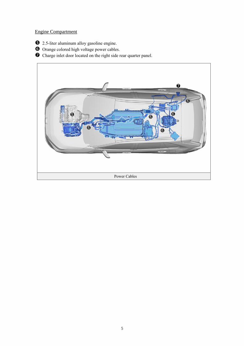
Engine Compartment
2.5-liter aluminum alloy gasoline engine.
Orange colored high voltage power cables.
Charge inlet door located on the right side rear quarter panel.
Power Cables
6
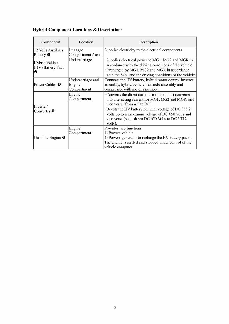
Hybrid Component Locations & Descriptions
Component Location Description
12 Volts Auxiliary
Battery
Luggage
Compartment Area
Supplies electricity to the electrical components.
Hybrid Vehicle
(HV) Battery Pack
Undercarriage •Supplies electrical power to MG1, MG2 and MGR in
accordance with the driving conditions of the vehicle.
•Recharged by MG1, MG2 and MGR in accordance
with the SOC and the driving conditions of the vehicle.
Power Cables
Undercarriage and
Engine
Compartment
Connects the HV battery, hybrid motor control inverter
assembly, hybrid vehicle transaxle assembly and
compressor with motor assembly.
Inverter/
Converter
Engine
Compartment •Converts the direct current from the boost converter
into alternating current for MG1, MG2 and MGR, and
vice versa (from AC to DC).
•Boosts the HV battery nominal voltage of DC 355.2
Volts up to a maximum voltage of DC 650 Volts and
vice versa (steps down DC 650 Volts to DC 355.2
Volts).
Gasoline Engine
Engine
Compartment
Provides two functions:
1) Powers vehicle.
2) Powers generator to recharge the HV battery pack.
The engine is started and stopped under control of the
vehicle computer.
7
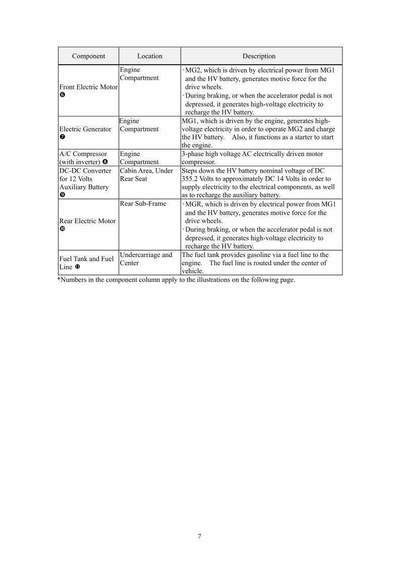
Component Location Description
Front Electric Motor
Engine
Compartment •MG2, which is driven by electrical power from MG1
and the HV battery, generates motive force for the
drive wheels.
•During braking, or when the accelerator pedal is not
depressed, it generates high-voltage electricity to
recharge the HV battery.
Electric Generator
Engine
Compartment
MG1, which is driven by the engine, generates high-
voltage electricity in order to operate MG2 and charge
the HV battery. Also, it functions as a starter to start
the engine.
A/C Compressor
(with inverter)
Engine
Compartment
3-phase high voltage AC electrically driven motor
compressor.
DC-DC Converter
for 12 Volts
Auxiliary Battery
Cabin Area, Under
Rear Seat
Steps down the HV battery nominal voltage of DC
355.2 Volts to approximately DC 14 Volts in order to
supply electricity to the electrical components, as well
as to recharge the auxiliary battery.
Rear Electric Motor
Rear Sub-Frame •MGR, which is driven by electrical power from MG1
and the HV battery, generates motive force for the
drive wheels.
•During braking, or when the accelerator pedal is not
depressed, it generates high-voltage electricity to
recharge the HV battery.
Fuel Tank and Fuel
Line
Undercarriage and
Center
The fuel tank provides gasoline via a fuel line to the
engine. The fuel line is routed under the center of
vehicle.
*Numbers in the component column apply to the illustrations on the following page.
8
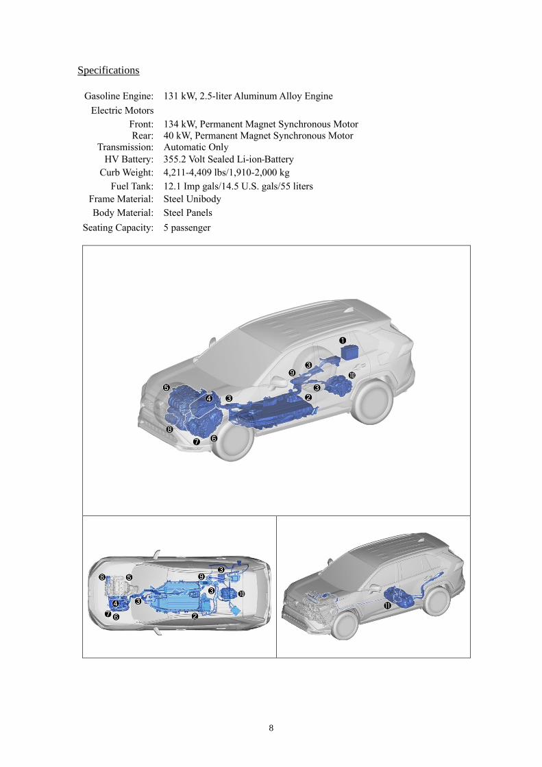
Specifications
Gasoline Engine: 131 kW, 2.5-liter Aluminum Alloy Engine
Electric Motors
Front:
Rear:
Transmission:
134 kW, Permanent Magnet Synchronous Motor
40 kW, Permanent Magnet Synchronous Motor
Automatic Only
HV Battery: 355.2 Volt Sealed Li-ion Battery
Curb Weight: 4,211-4,409 lbs/1,910-2,000 kg
Fuel Tank: 12.1 Imp gals/14.5 U.S. gals/55 liters
Frame Material: Steel Unibody
Body Material: Steel Panels
Seating Capacity: 5 passenger
9
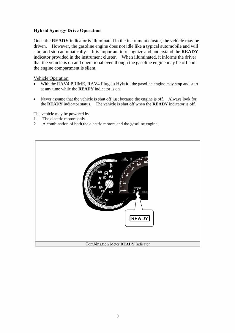
Hybrid Synergy Drive Operation
Once the READY indicator is illuminated in the instrument cluster, the vehicle may be
driven. However, the gasoline engine does not idle like a typical automobile and will
start and stop automatically. It is important to recognize and understand the READY
indicator provided in the instrument cluster. When illuminated, it informs the driver
that the vehicle is on and operational even though the gasoline engine may be off and
the engine compartment is silent.
Vehicle Operation
• With the RAV4 PRIME, RAV4 Plug-in Hybrid, the gasoline engine may stop and start
at any time while the READY indicator is on.
• Never assume that the vehicle is shut off just because the engine is off. Always look for
the READY indicator status. The vehicle is shut off when the READY indicator is off.
The vehicle may be powered by:
1. The electric motors only.
2. A combination of both the electric motors and the gasoline engine.
Combination Meter READY Indicator
10
Hybrid Vehicle (HV) Battery Pack and Auxiliary Battery
The RAV4 PRIME, RAV4 Plug-in Hybrid features a high voltage Hybrid Vehicle (HV)
battery pack that contains sealed Lithium-ion (Li-ion) battery cells.
HV Battery Pack
• The HV battery pack is enclosed in a metal case and is rigidly mounted to the undercarriage.
The metal case is isolated from high voltage.
• The HV battery pack consists of 96 low voltage (3.7 Volts) Li-ion battery cells connected in
series to produce approximately 355.2 Volts. Each Li-ion battery module is non-spillable
and sealed in a metal case.
• The electrolyte used in the Li-ion battery module is an alkaline mixture of potassium and
sodium hydroxide. The electrolyte is absorbed into the battery cell plates and will not
normally leak, even in a collision.
HV Battery Pack
Battery pack voltage 355.2 Volts
Number of Li-ion battery cells in the pack 96
Li-ion battery module voltage 3.7 Volts
Components Powered by the HV Battery Pack
• Front Electric Motor
• Rear Electric Motor
• Power Cables
• A/C Compressor
• Electric Generator
• Inverter/Converter
• DC-DC Converter for 12 Volts Auxiliary Battery
11
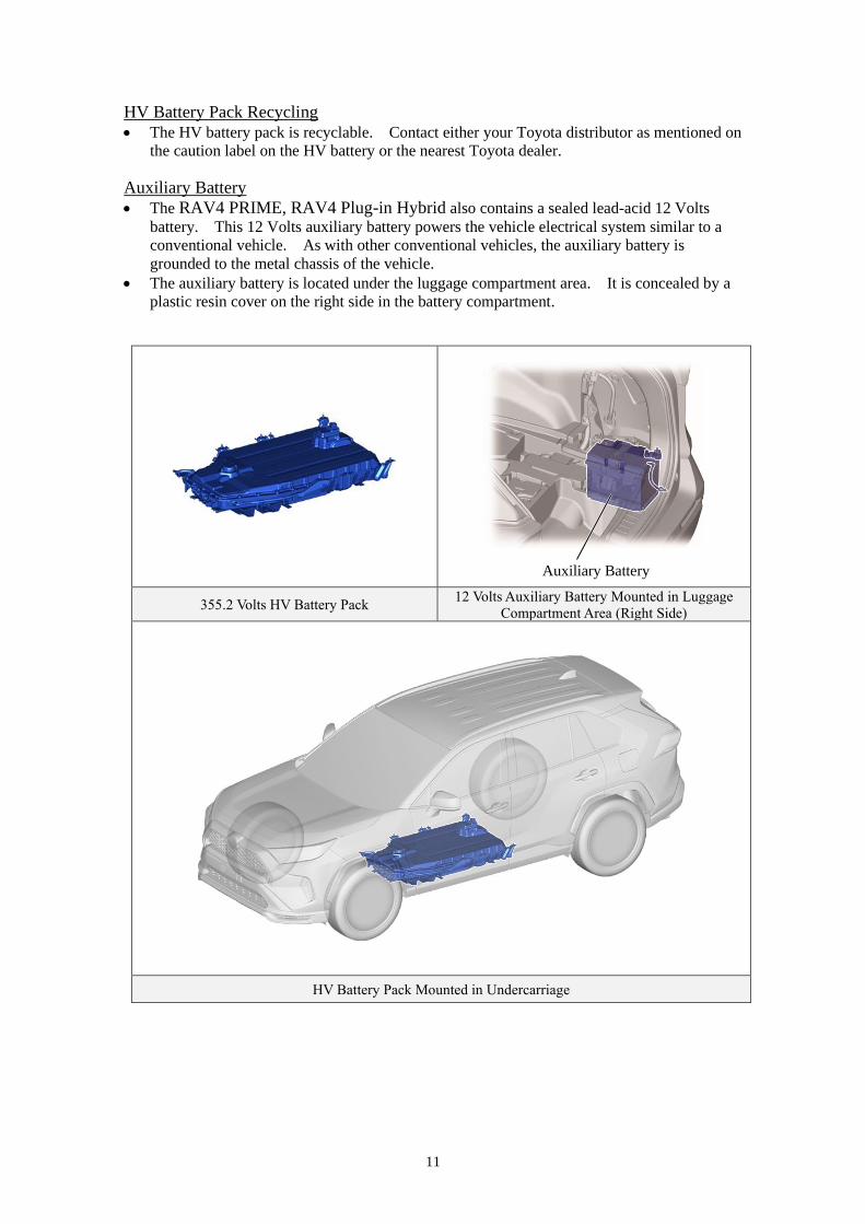
HV Battery Pack Recycling
• The HV battery pack is recyclable. Contact either your Toyota distributor as mentioned on
the caution label on the HV battery or the nearest Toyota dealer.
Auxiliary Battery
• The RAV4 PRIME, RAV4 Plug-in Hybrid also contains a sealed lead-acid 12 Volts
battery. This 12 Volts auxiliary battery powers the vehicle electrical system similar to a
conventional vehicle. As with other conventional vehicles, the auxiliary battery is
grounded to the metal chassis of the vehicle.
• The auxiliary battery is located under the luggage compartment area. It is concealed by a
plastic resin cover on the right side in the battery compartment.
355.2 Volts HV Battery Pack 12 Volts Auxiliary Battery Mounted in Luggage
Compartment Area (Right Side)
HV Battery Pack Mounted in Undercarriage
Auxiliary Battery
12
High Voltage Safety
The HV battery pack powers the high voltage electrical system with DC electricity. Positive
and negative orange colored high voltage power cables are routed from the battery pack, under
the vehicle floor pan, to the inverter/converter, A/C compressor, DC/DC converter and voltage
inverter assembly. The inverter/converter contains a circuit that boosts the HV battery voltage
from 355.2 to 650 Volts DC. The inverter/converter creates 3-phase AC to power the motors.
Power cables are routed from the inverter/converter to each high voltage motors (front and rear
electric motors, and electric generator). The following systems are intended to help keep
occupants in the vehicle and emergency responders safe from high voltage electricity:
High Voltage Safety System
• Positive and negative high voltage power cables * connected to the HV battery pack are
controlled by 12 Volts normally open relays *. When the vehicle is shut off, the relays
stop electricity flow from leaving the HV battery pack.
WARNING:
・ The high voltage system may remain powered for up to 10 minutes after the vehicle is shut off or disabled. To prevent serious injury or death from severe burns or electric shock, avoid touching, cutting, or opening any orange high voltage power cable or high voltage component.
• Both positive and negative power cables * are insulated from the metal body. High
voltage electricity flows through these cables and not through the metal vehicle body.
The metal vehicle body is safe to touch because it is insulated from the high voltage
components.
• A ground fault monitor * continuously monitors for high voltage leakage to the metal
chassis while the vehicle is running. If a malfunction is detected, the hybrid vehicle
computer * will a message indicating that the hybrid system is malfunctioning will be
displayed on the multi-information display.
• The HV battery pack relays will automatically open to stop electricity flow in a collision
sufficient to activate the SRS.
*Numbers apply to the illustration on the following page.
13
High Voltage Safety (Continued)
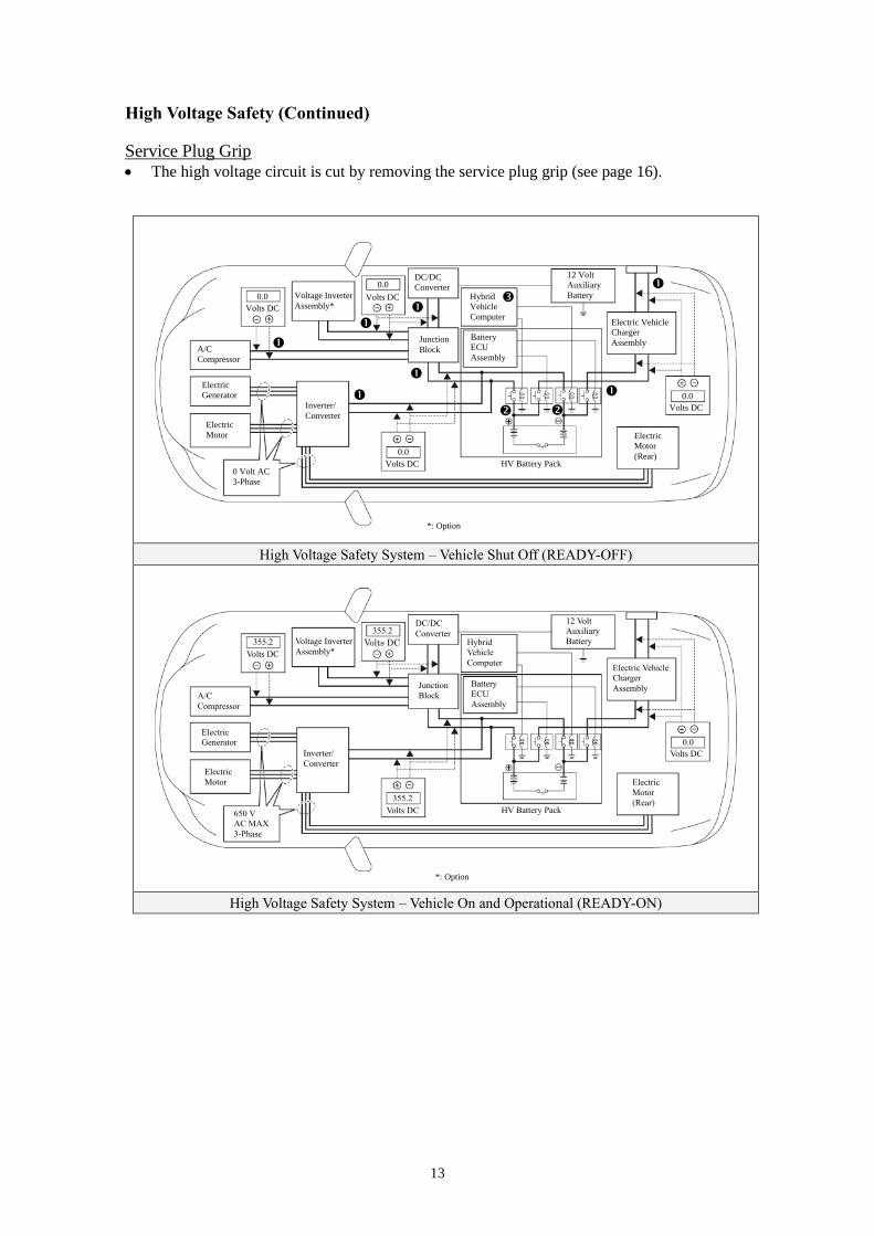
Service Plug Grip
• The high voltage circuit is cut by removing the service plug grip (see page 16).
High Voltage Safety System – Vehicle Shut Off (READY-OFF)
High Voltage Safety System – Vehicle On and Operational (READY-ON)
DC/DC
Converter
Junction
Block
HV Battery Pack
Hybrid
Vehicle
Computer Volts DC
A/C
Compressor
Electric
Generator
Electric
Motor
0.0
0 Volt AC
3-Phase
Voltage Inverter
Assembly*
12 Volt
Auxiliary
Battery
Volts DC
0.0
Electric Vehicle
Charger
Assembly
0.0
Volts DC
Battery
ECU
Assembly
Inverter/
Converter
0.0
Volts DC
Electric
Motor
(Rear)
DC/DC
Converter
Junction
Block
HV Battery Pack
Hybrid
Vehicle
Computer Volts DC
A/C
Compressor
Electric
Generator
Electric
Motor
650 V
AC MAX
3-Phase
Voltage Inverter
Assembly*
12 Volt
Auxiliary
Battery
Volts DC
355.2
Electric Vehicle
Charger
Assembly
Volts DC
Battery
ECU
Assembly
Inverter/
Converter
0.0
Volts DC
Electric
Motor
(Rear)
355.2
355.2
*: Option
*: Option
14
Precaution to be observed when dismantling the vehicle
WARNING:
・ The high voltage system may remain powered for up to 10
minutes after the vehicle is shut off or disabled. To prevent
serious injury or death from severe burns or electric shock,
avoid touching, cutting, or opening any orange high voltage
power cable or high voltage component.
Necessary Items
• Protective clothing such as insulated gloves (electrically insulated), rubber gloves, safety goggles,
and safety shoes.
• Insulating tape such as electrical tape that has a suitable electrical insulation rating.
• Before wearing insulated gloves, make sure that they are not cracked, ruptured, torn, or damaged in
any way. Do not wear wet insulated gloves.
• An electrical tester that is capable of measuring DC 750 Volts or more.
15
Spills
The RAV4 PRIME, RAV4 Plug-in Hybrid contains the same common automotive fluids used in other
non-hybrid Toyota vehicles, with the exception of the Li-ion electrolyte used in the HV battery pack.
The electrolyte used in the Li-ion battery cells is a flammable organic electrolyte. The electrolyte is
absorbed into the battery cell separators, even if the battery cells are crushed or cracked, it is unlikely
that liquid electrolyte will leak. Any liquid electrolyte that leaks from a Li-ion battery cell quickly
evaporates.
WARNING:
・ The Li-ion battery contains organic electrolyte. Only a small
amount may leak from the batteries which may irritate the eyes,
nose, throat, and skin.
・ Contact with the vapor produced by the electrolyte may irritate
the nose and throat.
・ To avoid injury by coming in contact with the electrolyte or vapor,
wear personal protective equipment for organic electrolyte
including SCBA or protective mask for organic gases.
• Handle Li-ion electrolyte spills using the following Personal Protective Equipment (PPE):
• Splash shield or safety goggles. A fold down face shield is not acceptable for acid or
electrolyte spills.
• Rubber gloves or gloves suitable for organic solvents.
• Apron suitable for organic solvents.
• Rubber boots or boots suitable for organic solvents.
• Protective mask for organic gases or SCBA.
16
Dismantling the vehicle
The following 5 pages contain general instructions for use when working on a RAV4 PRIME, RAV4
Plug-in Hybrid.
Read these instructions before proceeding to the HV battery removal instructions on page 21.
WARNING:
・ The high voltage system may remain powered for up to 10
minutes after the vehicle is shut off or disabled. To prevent
serious injury or death from severe burns or electric shock,
avoid touching, cutting, or opening any orange high voltage
power cable or any high voltage component.
Shut off the ignition (READY indicator is off).
Remove deck board assembly
Remove the deck board assembly.
Remove battery hole cover
Detach the 13 claws and remove the battery hole
cover.
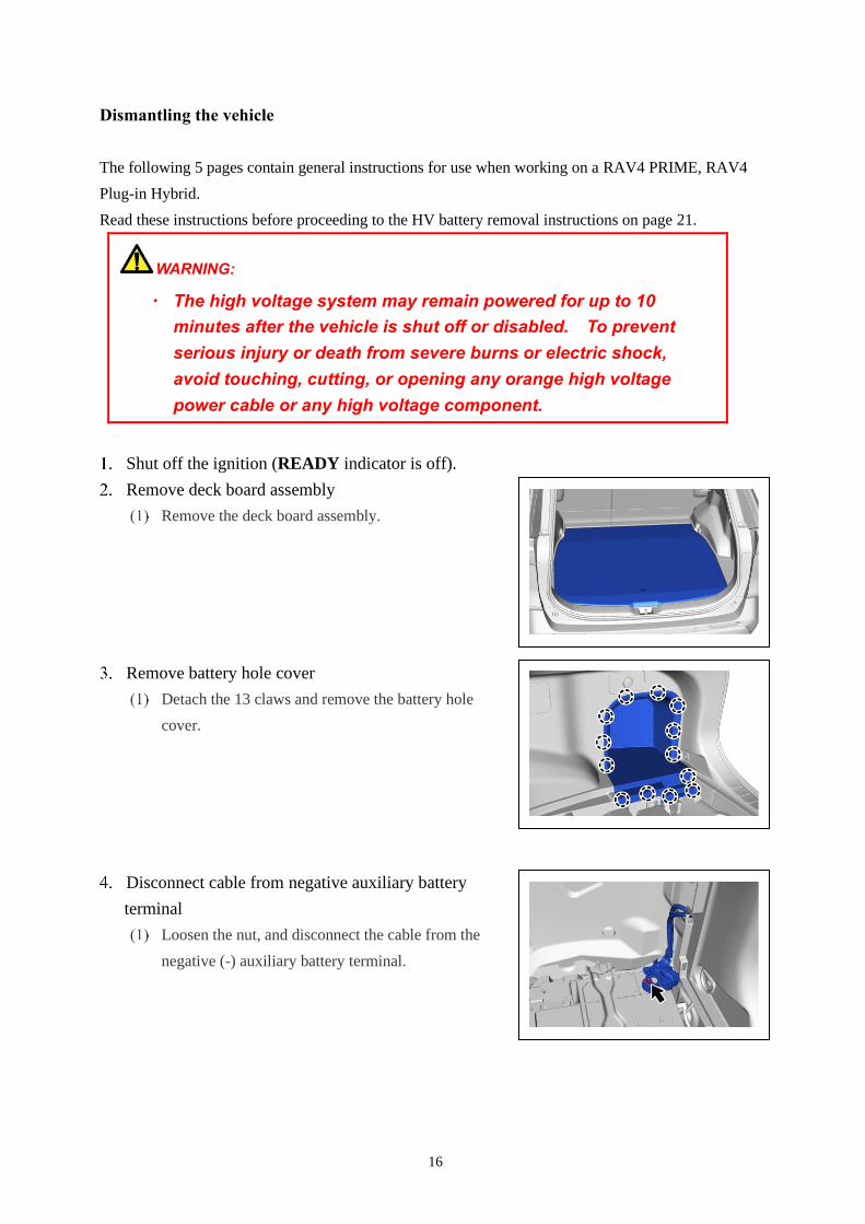
Disconnect cable from negative auxiliary battery
terminal
Loosen the nut, and disconnect the cable from the
negative (-) auxiliary battery terminal.
17
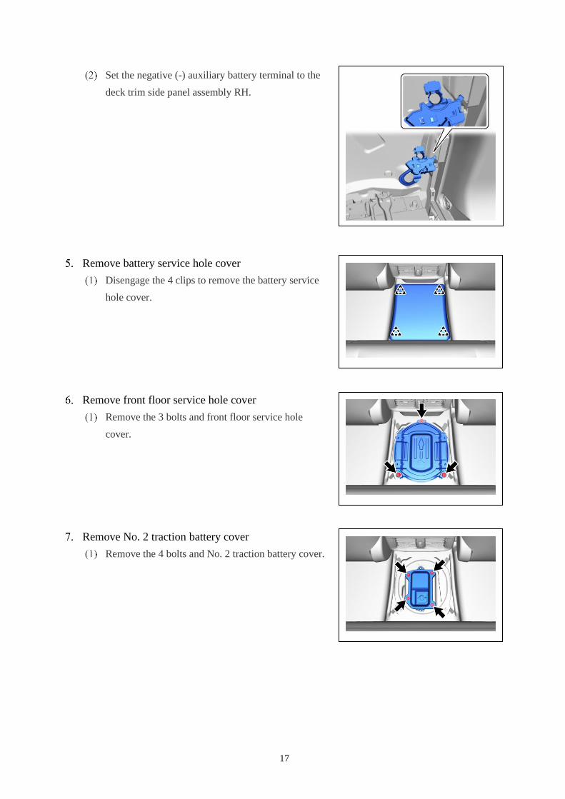
Set the negative (-) auxiliary battery terminal to the
deck trim side panel assembly RH.
Remove battery service hole cover
Disengage the 4 clips to remove the battery service
hole cover.
Remove front floor service hole cover
Remove the 3 bolts and front floor service hole
cover.
Remove No. 2 traction battery cover
Remove the 4 bolts and No. 2 traction battery cover.
18
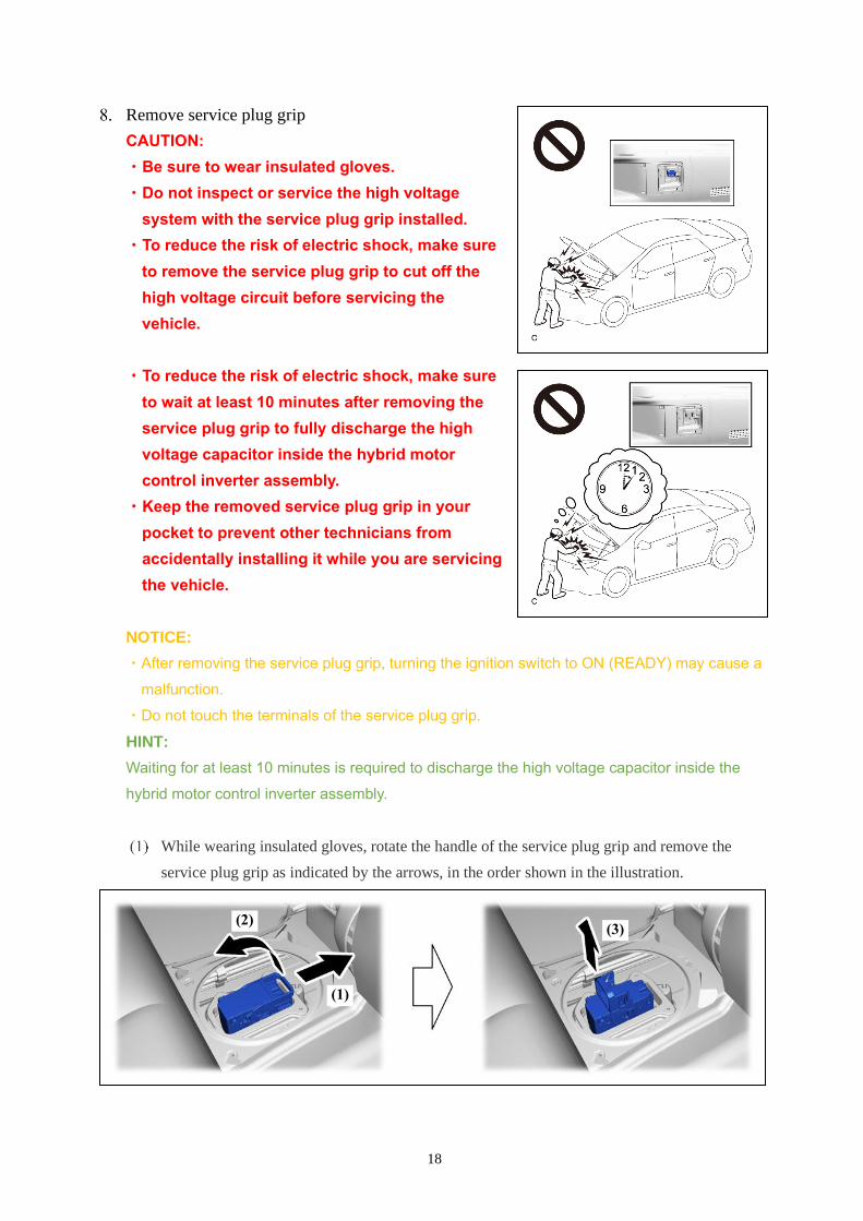
Remove service plug grip
CAUTION:
・Be sure to wear insulated gloves.
・Do not inspect or service the high voltage
system with the service plug grip installed.
・To reduce the risk of electric shock, make sure
to remove the service plug grip to cut off the
high voltage circuit before servicing the
vehicle.
・To reduce the risk of electric shock, make sure
to wait at least 10 minutes after removing the
service plug grip to fully discharge the high
voltage capacitor inside the hybrid motor
control inverter assembly.
・Keep the removed service plug grip in your
pocket to prevent other technicians from
accidentally installing it while you are servicing
the vehicle.
NOTICE:
・After removing the service plug grip, turning the ignition switch to ON (READY) may cause a
malfunction.
・Do not touch the terminals of the service plug grip.
HINT:
Waiting for at least 10 minutes is required to discharge the high voltage capacitor inside the
hybrid motor control inverter assembly.
While wearing insulated gloves, rotate the handle of the service plug grip and remove the
service plug grip as indicated by the arrows, in the order shown in the illustration.
(2)
(1)
(3)
19
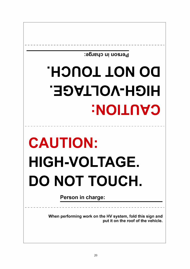
Make other staff aware that a high-voltage system is being dismantled by using the
following sign: CAUTION: HIGH-VOLTAGE. DO NOT TOUCH (see page 20).
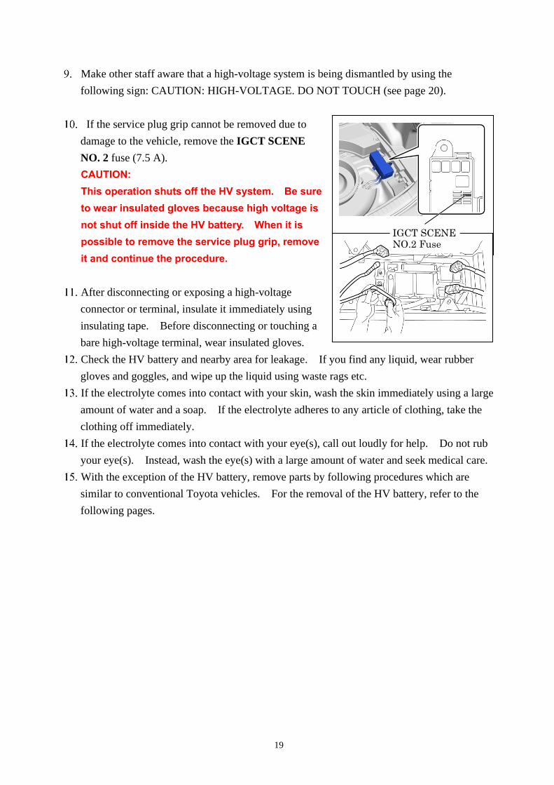
If the service plug grip cannot be removed due to
damage to the vehicle, remove the IGCT SCENE
NO. 2 fuse (7.5 A).
CAUTION:
This operation shuts off the HV system. Be sure
to wear insulated gloves because high voltage is
not shut off inside the HV battery. When it is
possible to remove the service plug grip, remove
it and continue the procedure.
After disconnecting or exposing a high-voltage
connector or terminal, insulate it immediately using
insulating tape. Before disconnecting or touching a
bare high-voltage terminal, wear insulated gloves.
Check the HV battery and nearby area for leakage. If you find any liquid, wear rubber
gloves and goggles, and wipe up the liquid using waste rags etc.
If the electrolyte comes into contact with your skin, wash the skin immediately using a large
amount of water and a soap. If the electrolyte adheres to any article of clothing, take the
clothing off immediately.
If the electrolyte comes into contact with your eye(s), call out loudly for help. Do not rub
your eye(s). Instead, wash the eye(s) with a large amount of water and seek medical care.
With the exception of the HV battery, remove parts by following procedures which are
similar to conventional Toyota vehicles. For the removal of the HV battery, refer to the
following pages.
IGCT SCENE NO.2 Fuse
20
21
Removal of HV battery
WARNING:
・ Be sure to wear insulated gloves when handling high-voltage
parts.
・ Even if the vehicle is shut off and the relays are off, be sure to
remove the service plug grip before performing any further
work.
・ Power remains in the high voltage electrical system for 10
minutes even after the HV battery pack is shut off because the
circuit has a condenser that stores power.
・ Make sure that the tester reading is 0 Volt before touching any
high-voltage terminals which are not insulated.
・ The SRS may remain powered for up to 90 seconds after the
vehicle is shut off or disabled. To prevent serious injury or
death from unintentional SRS deployment, avoid cutting the
SRS components.
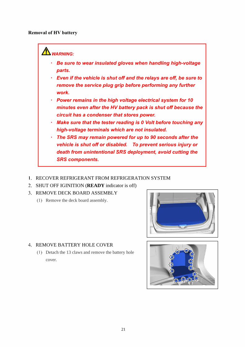
RECOVER REFRIGERANT FROM REFRIGERATION SYSTEM
SHUT OFF IGINITION (READY indicator is off)
REMOVE DECK BOARD ASSEMBLY
Remove the deck board assembly.
REMOVE BATTERY HOLE COVER
Detach the 13 claws and remove the battery hole
cover.
22
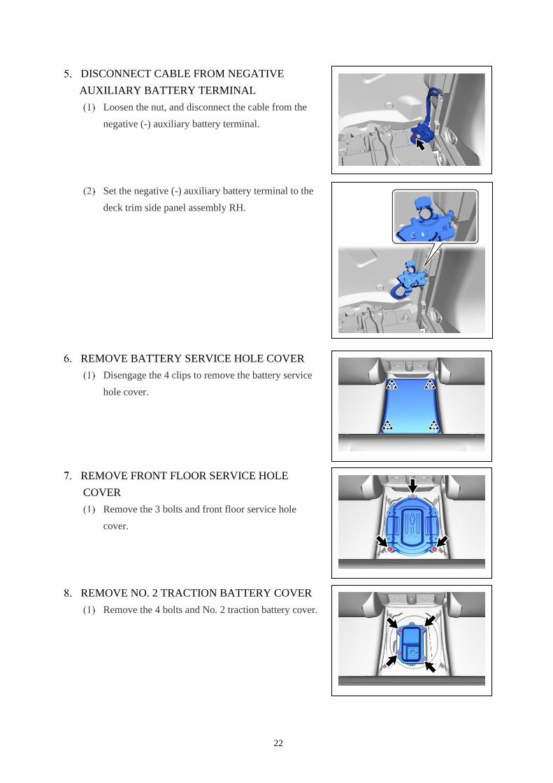
DISCONNECT CABLE FROM NEGATIVE
AUXILIARY BATTERY TERMINAL
Loosen the nut, and disconnect the cable from the
negative (-) auxiliary battery terminal.
Set the negative (-) auxiliary battery terminal to the
deck trim side panel assembly RH.
REMOVE BATTERY SERVICE HOLE COVER
Disengage the 4 clips to remove the battery service
hole cover.
REMOVE FRONT FLOOR SERVICE HOLE
COVER
Remove the 3 bolts and front floor service hole
cover.
REMOVE NO. 2 TRACTION BATTERY COVER
Remove the 4 bolts and No. 2 traction battery cover.
23
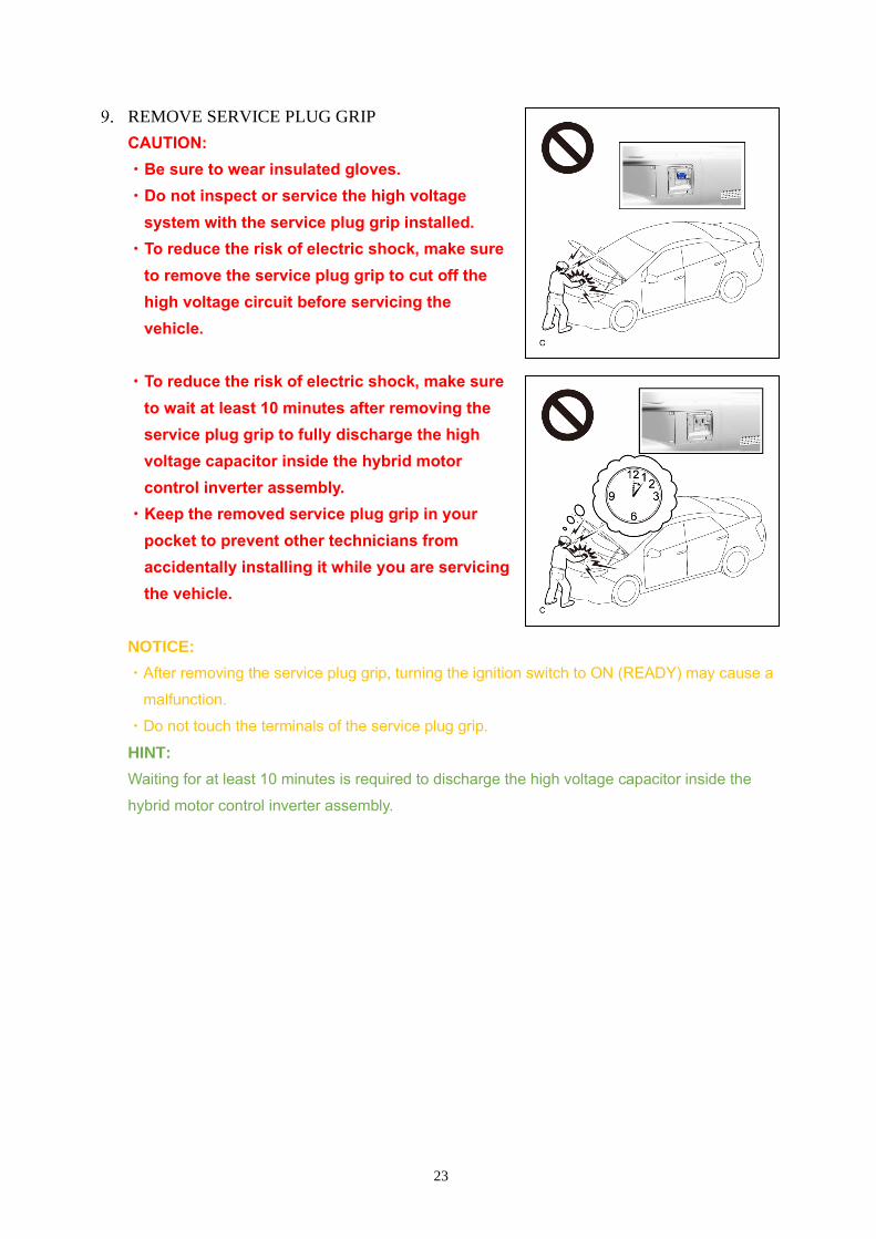
REMOVE SERVICE PLUG GRIP
CAUTION:
・Be sure to wear insulated gloves.
・Do not inspect or service the high voltage
system with the service plug grip installed.
・To reduce the risk of electric shock, make sure
to remove the service plug grip to cut off the
high voltage circuit before servicing the
vehicle.
・To reduce the risk of electric shock, make sure
to wait at least 10 minutes after removing the
service plug grip to fully discharge the high
voltage capacitor inside the hybrid motor
control inverter assembly.
・Keep the removed service plug grip in your
pocket to prevent other technicians from
accidentally installing it while you are servicing
the vehicle.
NOTICE:
・After removing the service plug grip, turning the ignition switch to ON (READY) may cause a
malfunction.
・Do not touch the terminals of the service plug grip.
HINT:
Waiting for at least 10 minutes is required to discharge the high voltage capacitor inside the
hybrid motor control inverter assembly.
24
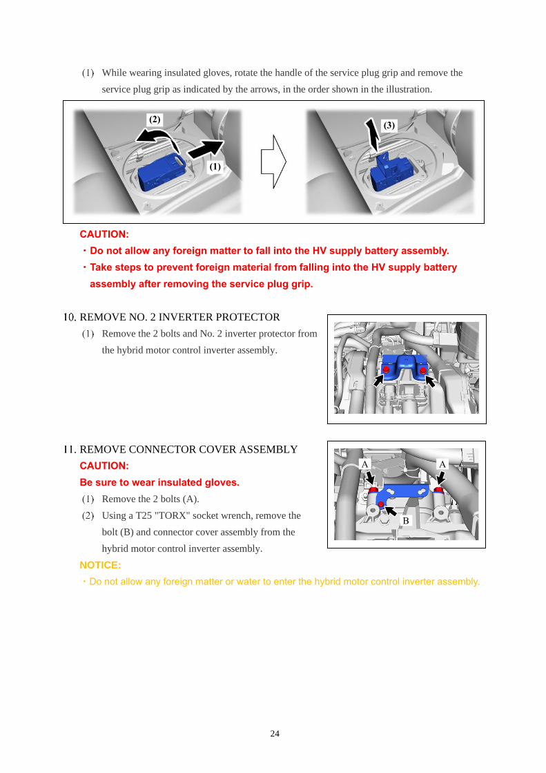
While wearing insulated gloves, rotate the handle of the service plug grip and remove the
service plug grip as indicated by the arrows, in the order shown in the illustration.
CAUTION:
・Do not allow any foreign matter to fall into the HV supply battery assembly.
・Take steps to prevent foreign material from falling into the HV supply battery
assembly after removing the service plug grip.
REMOVE NO. 2 INVERTER PROTECTOR
Remove the 2 bolts and No. 2 inverter protector from
the hybrid motor control inverter assembly.
REMOVE CONNECTOR COVER ASSEMBLY
CAUTION:
Be sure to wear insulated gloves.
Remove the 2 bolts (A).
Using a T25 "TORX" socket wrench, remove the
bolt (B) and connector cover assembly from the
hybrid motor control inverter assembly.
NOTICE:
・Do not allow any foreign matter or water to enter the hybrid motor control inverter assembly.
B
(2)
(1)
(3)
A A
25
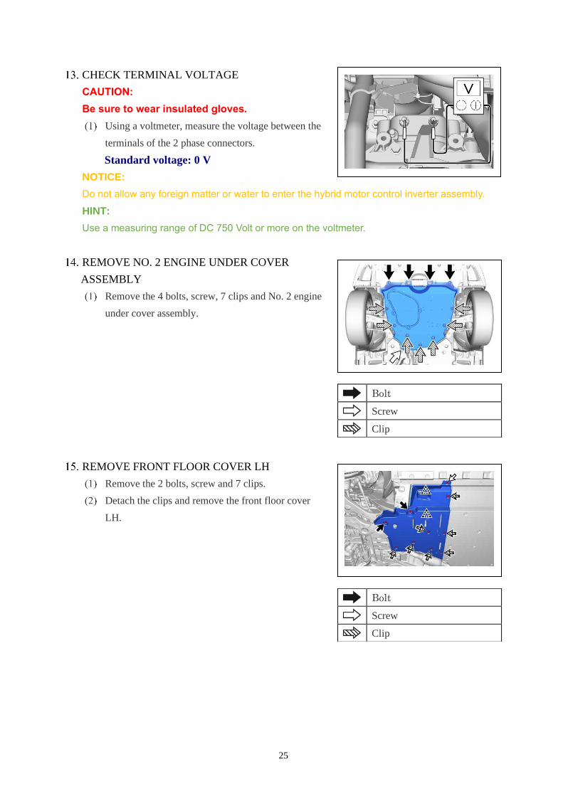
CHECK TERMINAL VOLTAGE
CAUTION:
Be sure to wear insulated gloves.
Using a voltmeter, measure the voltage between the
terminals of the 2 phase connectors.
Standard voltage: 0 V
NOTICE:
Do not allow any foreign matter or water to enter the hybrid motor control inverter assembly.
HINT:
Use a measuring range of DC 750 Volt or more on the voltmeter.
REMOVE NO. 2 ENGINE UNDER COVER
ASSEMBLY
Remove the 4 bolts, screw, 7 clips and No. 2 engine
under cover assembly.
REMOVE FRONT FLOOR COVER LH
Remove the 2 bolts, screw and 7 clips.
Detach the clips and remove the front floor cover
LH.
Bolt
Screw
Clip
Bolt
Screw
Clip
26
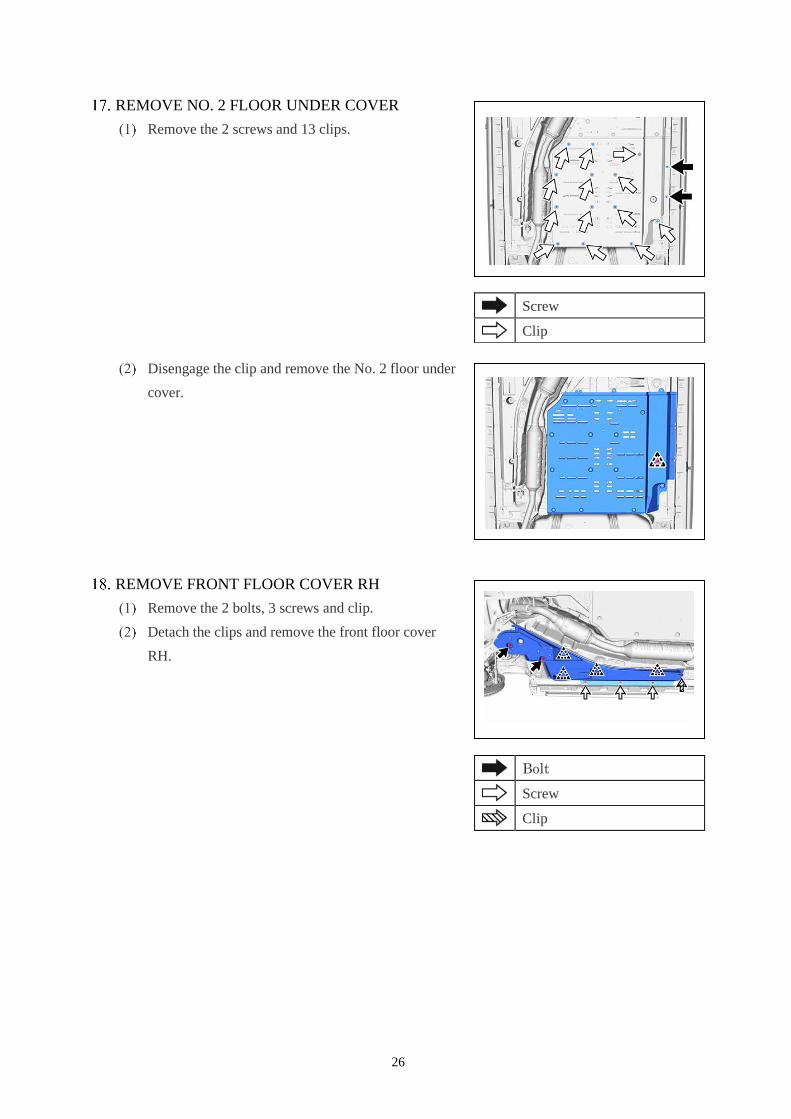
REMOVE NO. 2 FLOOR UNDER COVER
Remove the 2 screws and 13 clips.
Disengage the clip and remove the No. 2 floor under
cover.
REMOVE FRONT FLOOR COVER RH
Remove the 2 bolts, 3 screws and clip.
Detach the clips and remove the front floor cover
RH.
Screw
Clip
Bolt
Screw
Clip
27
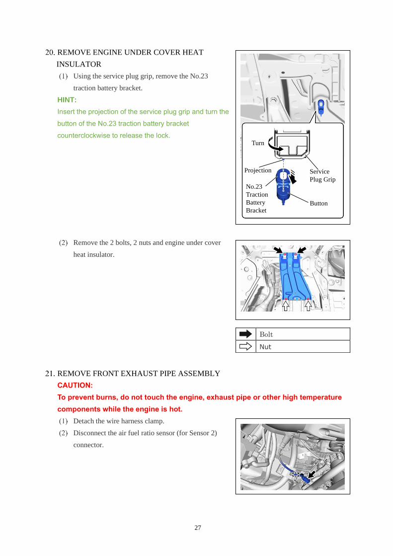
REMOVE ENGINE UNDER COVER HEAT
INSULATOR
Using the service plug grip, remove the No.23
traction battery bracket.
HINT:
Insert the projection of the service plug grip and turn the
button of the No.23 traction battery bracket
counterclockwise to release the lock.
Remove the 2 bolts, 2 nuts and engine under cover
heat insulator.
REMOVE FRONT EXHAUST PIPE ASSEMBLY
CAUTION:
To prevent burns, do not touch the engine, exhaust pipe or other high temperature
components while the engine is hot.
Detach the wire harness clamp.
Disconnect the air fuel ratio sensor (for Sensor 2)
connector.
Bolt
Nut
Service
Plug Grip
Turn
No.23
Traction
Battery
Bracket Button
Projection
28
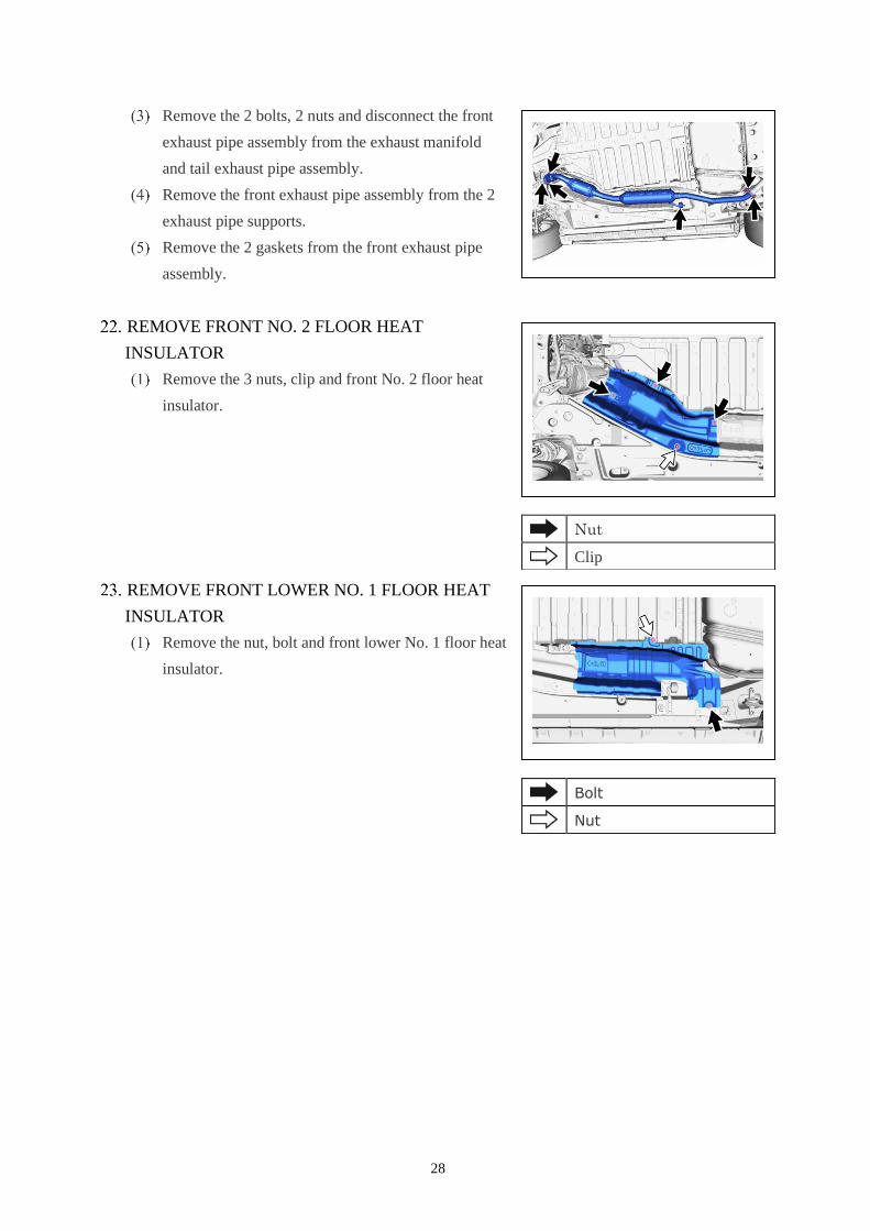
Remove the 2 bolts, 2 nuts and disconnect the front
exhaust pipe assembly from the exhaust manifold
and tail exhaust pipe assembly.
Remove the front exhaust pipe assembly from the 2
exhaust pipe supports.
Remove the 2 gaskets from the front exhaust pipe
assembly.
REMOVE FRONT NO. 2 FLOOR HEAT
INSULATOR
Remove the 3 nuts, clip and front No. 2 floor heat
insulator.
REMOVE FRONT LOWER NO. 1 FLOOR HEAT
INSULATOR
Remove the nut, bolt and front lower No. 1 floor heat
insulator.
Nut
Clip
Bolt
Nut
29
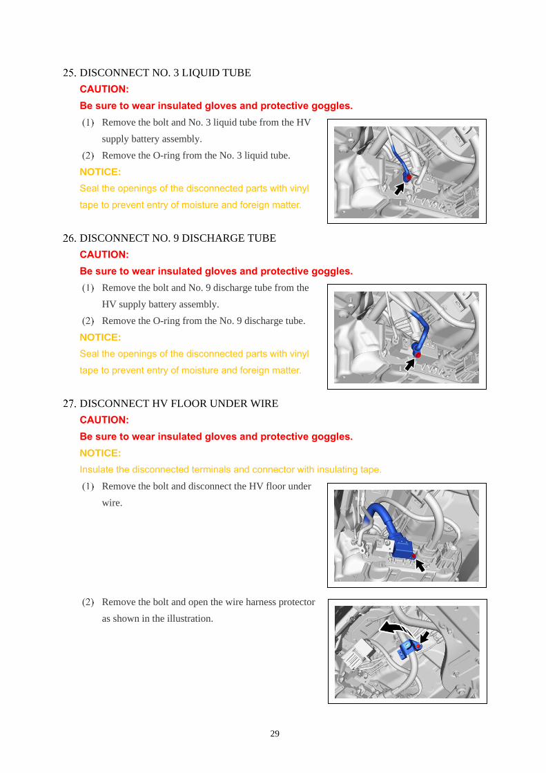
DISCONNECT NO. 3 LIQUID TUBE
CAUTION:
Be sure to wear insulated gloves and protective goggles.
Remove the bolt and No. 3 liquid tube from the HV
supply battery assembly.
Remove the O-ring from the No. 3 liquid tube.
NOTICE:
Seal the openings of the disconnected parts with vinyl
tape to prevent entry of moisture and foreign matter.
DISCONNECT NO. 9 DISCHARGE TUBE
CAUTION:
Be sure to wear insulated gloves and protective goggles.
Remove the bolt and No. 9 discharge tube from the
HV supply battery assembly.
Remove the O-ring from the No. 9 discharge tube.
NOTICE:
Seal the openings of the disconnected parts with vinyl
tape to prevent entry of moisture and foreign matter.
DISCONNECT HV FLOOR UNDER WIRE
CAUTION:
Be sure to wear insulated gloves and protective goggles.
NOTICE:
Insulate the disconnected terminals and connector with insulating tape.
Remove the bolt and disconnect the HV floor under
wire.
Remove the bolt and open the wire harness protector
as shown in the illustration.
30
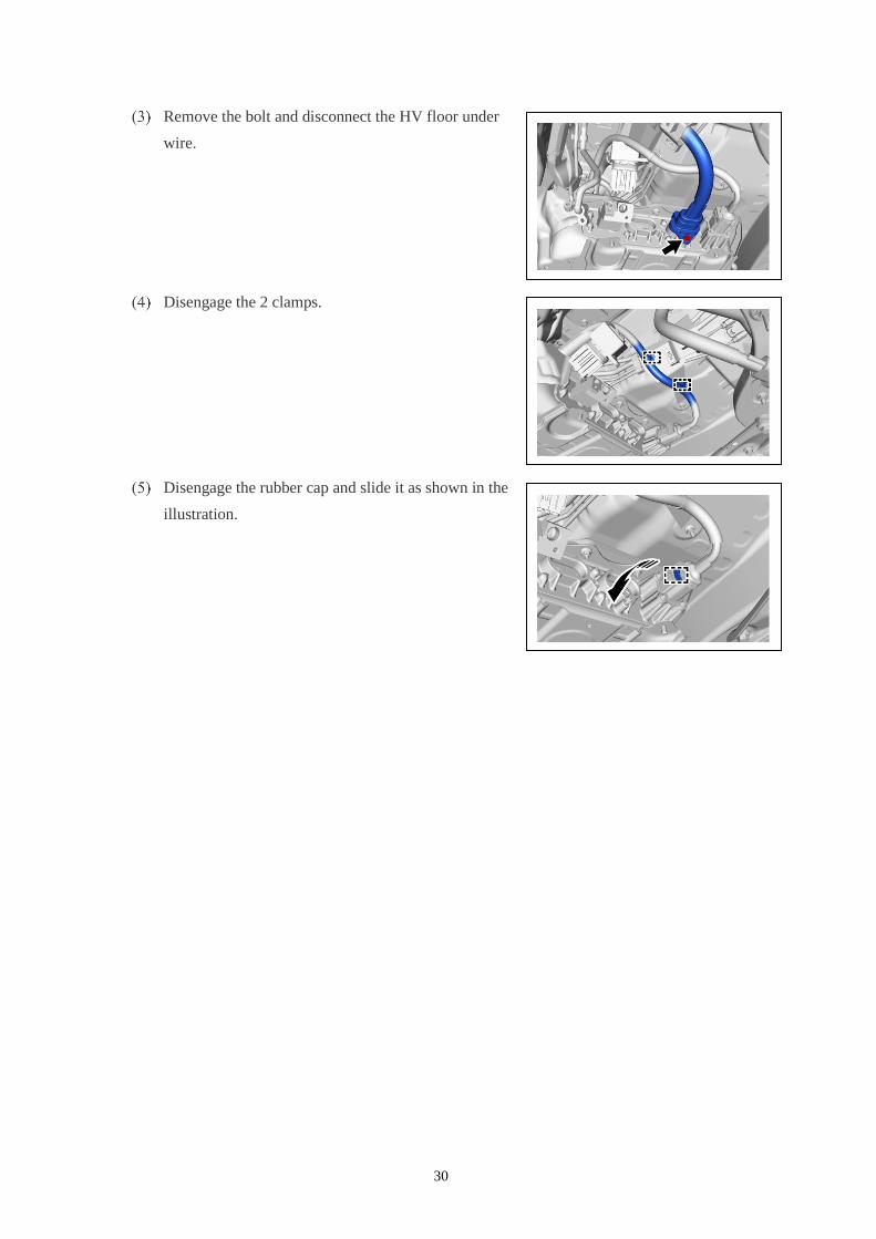
Remove the bolt and disconnect the HV floor under
wire.
Disengage the 2 clamps.
Disengage the rubber cap and slide it as shown in the
illustration.
31
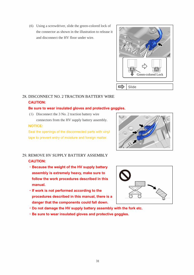
Using a screwdriver, slide the green-colored lock of
the connector as shown in the illustration to release it
and disconnect the HV floor under wire.
DISCONNECT NO. 2 TRACTION BATTERY WIRE
CAUTION:
Be sure to wear insulated gloves and protective goggles.
Disconnect the 3 No. 2 traction battery wire
connectors from the HV supply battery assembly.
NOTICE:
Seal the openings of the disconnected parts with vinyl
tape to prevent entry of moisture and foreign matter.
REMOVE HV SUPPLY BATTERY ASSEMBLY
CAUTION:
・Because the weight of the HV supply battery
assembly is extremely heavy, make sure to
follow the work procedures described in this
manual.
・If work is not performed according to the
procedures described in this manual, there is a
danger that the components could fall down.
・Do not damage the HV supply battery assembly with the fork etc.
・Be sure to wear insulated gloves and protective goggles.
Slide
Green-colored Lock
32
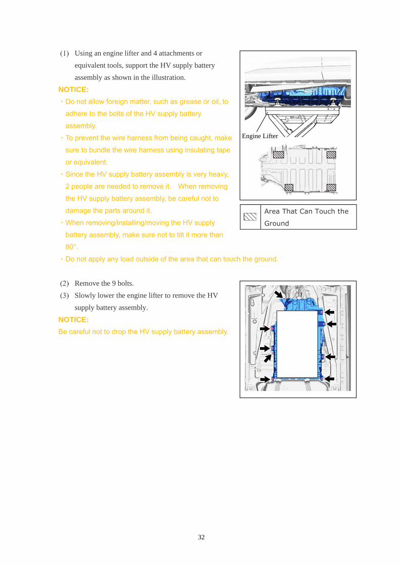
Using an engine lifter and 4 attachments or
equivalent tools, support the HV supply battery
assembly as shown in the illustration.
NOTICE:
・Do not allow foreign matter, such as grease or oil, to
adhere to the bolts of the HV supply battery
assembly.
・To prevent the wire harness from being caught, make
sure to bundle the wire harness using insulating tape
or equivalent.
・Since the HV supply battery assembly is very heavy,
2 people are needed to remove it. When removing
the HV supply battery assembly, be careful not to
damage the parts around it.
・When removing/installing/moving the HV supply
battery assembly, make sure not to tilt it more than
80°.
・Do not apply any load outside of the area that can touch the ground.
Remove the 9 bolts.
Slowly lower the engine lifter to remove the HV
supply battery assembly.
NOTICE:
Be careful not to drop the HV supply battery assembly.
Area That Can Touch the
Ground
Engine Lifter
33
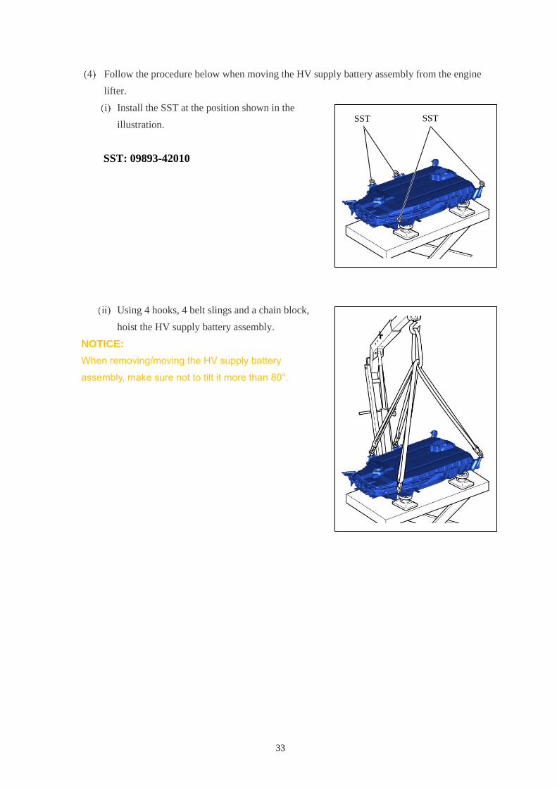
Follow the procedure below when moving the HV supply battery assembly from the engine
lifter.
Install the SST at the position shown in the
illustration.
SST: 09893-42010
Using 4 hooks, 4 belt slings and a chain block,
hoist the HV supply battery assembly.
NOTICE:
When removing/moving the HV supply battery
assembly, make sure not to tilt it more than 80°.
SST SST
34
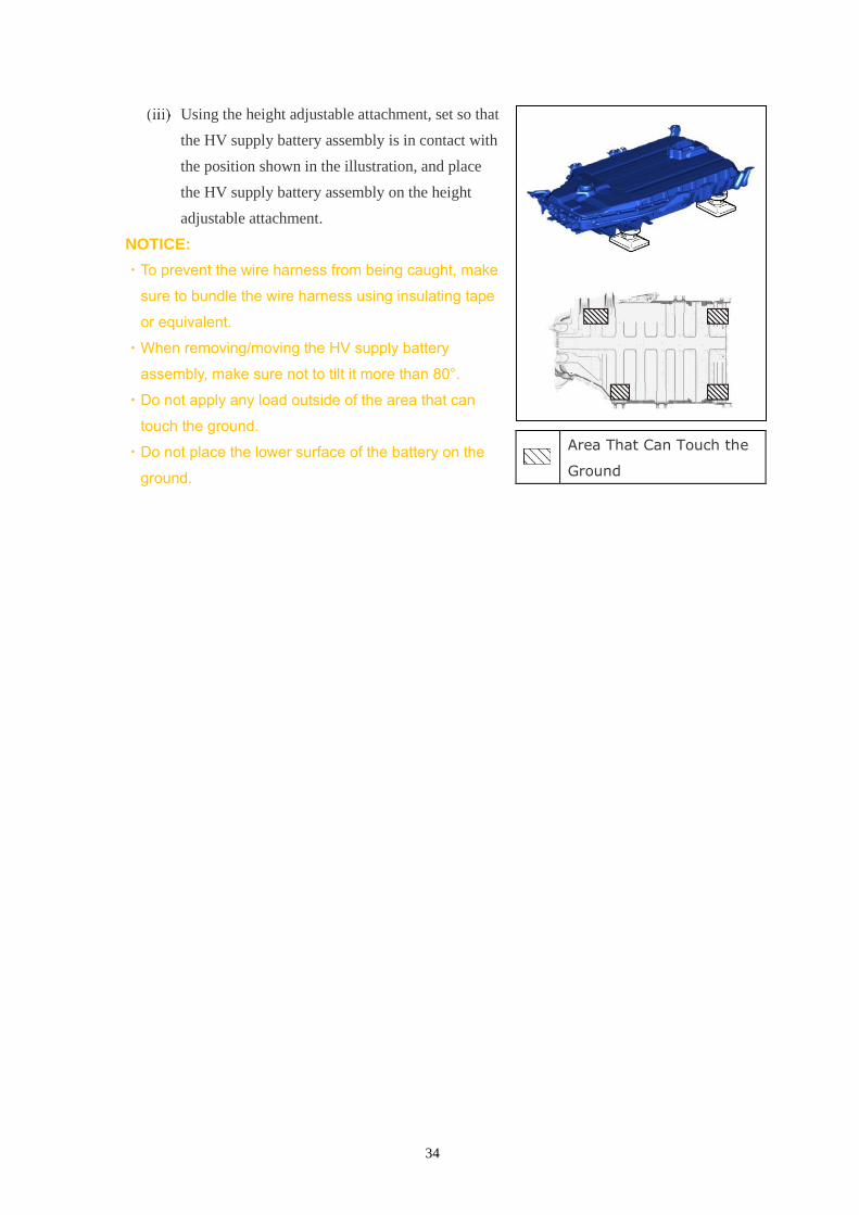
Using the height adjustable attachment, set so that
the HV supply battery assembly is in contact with
the position shown in the illustration, and place
the HV supply battery assembly on the height
adjustable attachment.
NOTICE:
・To prevent the wire harness from being caught, make
sure to bundle the wire harness using insulating tape
or equivalent.
・When removing/moving the HV supply battery
assembly, make sure not to tilt it more than 80°.
・Do not apply any load outside of the area that can
touch the ground.
・Do not place the lower surface of the battery on the
ground.
Area That Can Touch the
Ground