Embed Size (px)
Citation preview
651
SP-230—38
Rationale for the ACI 440.1R-06 IndirectDeflection Control Design Provisions
by C.E. Ospina and S.P. Gross
Synopsis: Compared to ordinary steel reinforcement, Fiber-Reinforced Polymer (FRP)reinforcing bars have a lower stiffness, display a brittle-elastic response, and possessparticular bond characteristics. The dependence on these distinctive features makesdeflection control in FRP-reinforced concrete beams and one-way slabs a moreelaborate process compared to the traditional serviceability design of steel-reinforcedmembers. This paper reports the rationale and fundamental concepts backing theindirect deflection control procedure for concrete beams and one-way slabs reinforcedwith FRP bars adopted by ACI 440.1R-06. The fundamental procedure can be appliedregardless of the type of reinforcement; it is independent of the member’s stiffnessthrough the cracked stage; and it is expressed as a function of the deflection-spanratio, which allows designers to fully control deflections depending on applicableserviceability limits. The paper also explains the simplifications made to thefundamental procedure that led to the development of the indirect deflection controlprocedure in tabular form found in ACI 440.1R-06, including the method by whichtension stiffening effects are accounted for.
Keywords: deflection; FRP-reinforced members; indirect deflectioncontrol; one-way slabs; serviceability design; tension stiffening
652 Ospina and GrossCarlos E. Ospina, Ph.D., P.E., is a Senior Engineer with Berger/ABAM Engineers Inc.,
USA, where he has been involved in the structural design/assessment of industrial
buildings, monorail guideways, nuclear plant cranes, underground facilities and
waterfront structures. He is a Member of ACI 314, Simplified Design of Concrete
Buildings, and an Associate Member of ACI 440, Fiber-Reinforced Polymers, ASCE-
ACI 423, Prestressed Concrete, and ACI 318S, Spanish Translation of ACI 318.
Shawn P. Gross, Ph.D., is an Associate Professor in the Department of Civil and
Environmental Engineering at Villanova University in Villanova, PA, USA. He is
Secretary of Joint ASCE-ACI Committee 423, Prestressed Concrete; a Member of ACI
Committee 363, High Strength Concrete, a Member of ACI Committee E803, Faculty
Network Coordinating Committee, and an Associate Member of ACI Committee 440,
Fiber-Reinforced Polymers.
INTRODUCTION
For serviceability design of FRP-reinforced members, ACI 440.1R-06 provides guidance on preliminary sizing of concrete beams and one-way slabs through an indirectdeflection control procedure that is expressed in terms of minimum beam and one-way slab thickness requirements. The designer is then required to calculate deflectionsdirectly based on a modification of the traditional Branson’s effective moment of inertia equation because, unlike in ACI 318-05, the indirect deflection control procedure in ACI440.1R-06 is not intended to waive the direct deflection control calculation.
The procedure used here to develop the indirect deflection control provisions in ACI 440.1R-06 can be applied to any type of reinforcement. It is also independent of the member’s stiffness, which is difficult to evaluate through the cracked stage, and it is directly related to a deflection-span ratio, which allows designers to control theserviceability design depending on applicable deflection limits. After presenting the general procedure, the paper explains the development of the minimum thickness tablefound in ACI 440.1R-06. The fundamental assumptions used in the simplification of the general procedure are identified, and the method by which the procedure is adjusted fortension stiffening effects is presented.
BACKGROUND
Deflections of reinforced concrete beams and one-way slabs can be controlled directly or indirectly. Direct deflection control refers to the calculation of deflections and their comparison with allowable limits. Direct methods span from traditional elastic theory toadvanced finite element analyses. ACI Committee 435 (1974) and Branson (1977) report comprehensive summaries of classic direct deflection control procedures for steel-reinforced concrete beams and flat plates. Indirect deflection control procedures limitdeflections by determining maximum span-depth ratios, minimum depths, or minimumtension reinforcement ratios (ACI Committee 435, 1978) that satisfy a given deflection-span ratio, ∆m/L. The latter is defined by experience. In the context of steel-reinforcedmembers, Branson (1977) recommends using indirect procedures for initial memberproportioning and then checking deflections directly. Deflections can also be controlled
FRPRCS-7 653by means of appropriate construction practice. Precambering and delaying removal of forms are some of the preferred options.
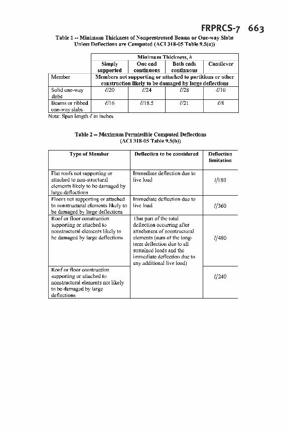
Deflection control provisions for steel-reinforced beams and one-way slabs in ACI318-05 are concerned with deflections that occur at service levels due to immediate andsustained static loads. Effects from dynamic loads such as earthquakes, winds, or vibration of machinery are not considered. Two methods are given: i) the indirectmethod of controlling the minimum thickness of the member (ACI 318 Table 9.5a); and ii) the direct method of limiting computed deflections (ACI 318 Table 9.5b). The choice of method is left to the discretion of the designer. Table 1 shows values of minimumthickness for non-prestressed steel-reinforced beams and one-way slabs per ACI 318-05expressed as maximum span-depth ratios. Table 2 shows the allowable deflections per ACI 318-05.
The direct deflection control design provisions for FRP-reinforced concrete beamsand one-way slabs in ACI 440.1R-06 follow a format similar to that of ACI 318-05.Deflections are calculated directly using a modified version of Branson’s effectivemoment of inertia equation, developed by Gao, Benmokrane and Masmoudi (1998). Based on recent data published by Yost, Gross, and Dinehart (2003) and other researchers, the equation used in earlier versions of ACI 440.1 was modified by thesecond author and adopted by ACI Committee 440 for inclusion in ACI 440.1R-06.
At its Washington D.C. 2004 Spring meeting, ACI Sub-committee 440H commissioned the authors to develop an indirect deflection control table similar to Table 9.5(a) of ACI 318 to define maximum span-depth ratios for FRP-reinforced concretebeams and one-way slabs, based on the indirect deflection control approach proposed by Ospina, Alexander, and Cheng (2001). The goal of the sub-committee was to providedesigners guidance for preliminary sizing of members in the form of typical span-depth ratios required to satisfy serviceability design criteria. The indirect deflection control table developed by the authors, which may be found in Appendix A, was approved byACI 440 in its San Francisco 2004 Fall meeting. Presentation of the rationale behind the development of this table constitutes the main subject of this paper.
PROPOSED INDIRECT DEFLECTION CONTROL PROCEDURE
As reported by Branson (1977), the instantaneous midspan deflection, ∆m, of a reinforced concrete beam or one-way slab subjected to a uniformly distributed load can be calculated as
=
ec
m
m
IE
LM
K
2
1
48
5
∆ (1)
where Mm is the midspan bending moment, L is the span length, E
c is concrete's elastic
modulus, and Ie is an effective moment of inertia. The constant K
1 depends only on
boundary conditions, and is defined as
654 Ospina and Gross
m
o
M
M
K 2.02.11
−= (2)
where Mo is the statical moment, i.e.
8
2
wL
Mo
= , K1 = 1 for simply supported spans, K
1 =
0.8 for fixed-hinged beams, and K1
= 0.6 for fixed-fixed beams. For cantilevered spans,
K1
= 2.4, Mm is replaced with the moment at the support, and ∆
m is replaced with the
deflection at the free end. In Eq. 2, both Mo and M
m result from the same loading.
Due to the difficulty in evaluating Ie to account for cracking effects on flexuralstiffness, Eq. 1 can be rewritten independent of Ie (Ospina, Alexander and Cheng 2001) as
2
1
48
5
LKmm
ψ∆
= (3)
where ψm is the curvature at midspan. Assuming cracked-elastic behavior,
( )m
rm
m
kd −
=
1
ε
ψ (4)
where ε rm
is the reinforcement strain at midspan (or support for a cantilevered span), d is
the effective flexural depth, and km is the ratio of the neutral axis depth to the flexural
depth, also at midspan (or support for a cantilevered span), calculated as
( )rrrm
nnnk ρρρ −+= 2
2
(5)
where n is the modular ratio, cr
EEn = , and ρr is the reinforcement ratio. Dividing both
sides of Eq. 3 by L and substituting Eq. 4 into 3 leads to
( )
L
kd
K
Lm
rmm
−
=
148
5
1
ε∆
(6)
Rearranging terms and setting h
d=η , the maximum span-depth ratio is given by
L
k
Kh
Lm
rm
m
∆
ε
η
−
≤
1
5
48
1
(7)
where �η may be assumed to vary from 0.85 to 0.95.
In Eq. 7, both the reinforcement strain and the neutral axis location define a limitingcurvature that is consistent with an allowable deflection-span ratio. The interdependenceof the reinforcement strain, the deflection-span ratio and the span-depth ratio is further
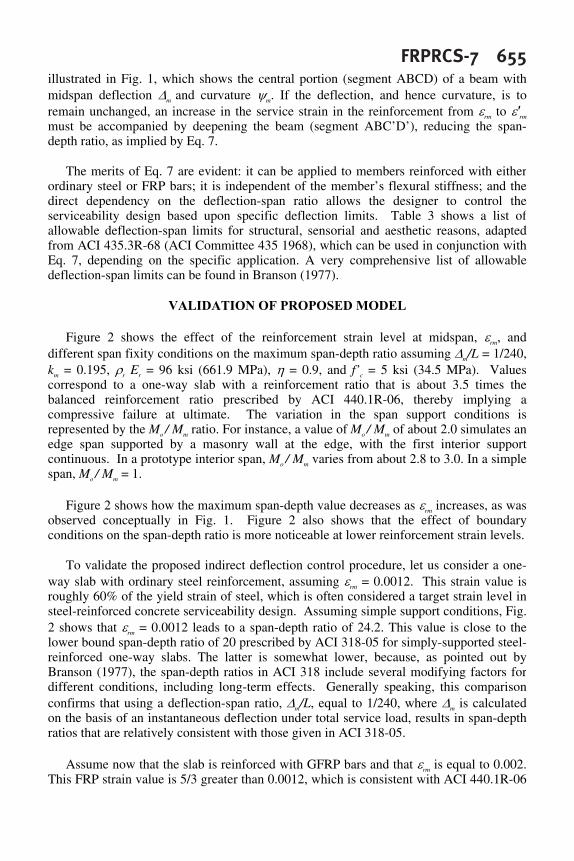
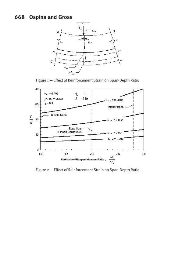
FRPRCS-7 655illustrated in Fig. 1, which shows the central portion (segment ABCD) of a beam withmidspan deflection ∆m and curvature ψm. If the deflection, and hence curvature, is toremain unchanged, an increase in the service strain in the reinforcement from εrm to ε'rm must be accompanied by deepening the beam (segment ABC’D’), reducing the span-depth ratio, as implied by Eq. 7.
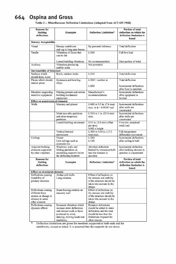
The merits of Eq. 7 are evident: it can be applied to members reinforced with eitherordinary steel or FRP bars; it is independent of the member’s flexural stiffness; and thedirect dependency on the deflection-span ratio allows the designer to control theserviceability design based upon specific deflection limits. Table 3 shows a list of allowable deflection-span limits for structural, sensorial and aesthetic reasons, adaptedfrom ACI 435.3R-68 (ACI Committee 435 1968), which can be used in conjunction with Eq. 7, depending on the specific application. A very comprehensive list of allowabledeflection-span limits can be found in Branson (1977).
VALIDATION OF PROPOSED MODEL
Figure 2 shows the effect of the reinforcement strain level at midspan, εrm, and different span fixity conditions on the maximum span-depth ratio assuming ∆m/L = 1/240,km = 0.195, ρr Er = 96 ksi (661.9 MPa), η = 0.9, and f’c = 5 ksi (34.5 MPa). Values correspond to a one-way slab with a reinforcement ratio that is about 3.5 times thebalanced reinforcement ratio prescribed by ACI 440.1R-06, thereby implying a compressive failure at ultimate. The variation in the span support conditions is represented by the Mo / Mm ratio. For instance, a value of Mo / Mm of about 2.0 simulates anedge span supported by a masonry wall at the edge, with the first interior support continuous. In a prototype interior span, Mo / Mm varies from about 2.8 to 3.0. In a simplespan, Mo / Mm = 1.
Figure 2 shows how the maximum span-depth value decreases as εrm increases, as was observed conceptually in Fig. 1. Figure 2 also shows that the effect of boundaryconditions on the span-depth ratio is more noticeable at lower reinforcement strain levels.
To validate the proposed indirect deflection control procedure, let us consider a one-way slab with ordinary steel reinforcement, assuming εrm = 0.0012. This strain value is roughly 60% of the yield strain of steel, which is often considered a target strain level in steel-reinforced concrete serviceability design. Assuming simple support conditions, Fig.2 shows that εrm = 0.0012 leads to a span-depth ratio of 24.2. This value is close to thelower bound span-depth ratio of 20 prescribed by ACI 318-05 for simply-supported steel-reinforced one-way slabs. The latter is somewhat lower, because, as pointed out byBranson (1977), the span-depth ratios in ACI 318 include several modifying factors fordifferent conditions, including long-term effects. Generally speaking, this comparisonconfirms that using a deflection-span ratio, ∆m/L, equal to 1/240, where ∆m is calculatedon the basis of an instantaneous deflection under total service load, results in span-depthratios that are relatively consistent with those given in ACI 318-05.
Assume now that the slab is reinforced with GFRP bars and that εrm is equal to 0.002.This FRP strain value is 5/3 greater than 0.0012, which is consistent with ACI 440.1R-06
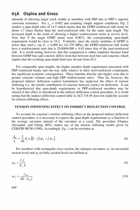
656 Ospina and Grossrationale of allowing larger crack widths in members with FRP due to FRP’s superior corrosion resistance. For εrm = 0.002 and assuming simple support conditions, Fig. 2renders a span-depth ratio of 14.5 which means that the GFRP-reinforced slab needs beabout 1.7 times thicker than the steel-reinforced slab, for the same span length. Theincreased depth is the result of allowing a higher reinforcement strain at service level. Note that if the target GFRP strain were 0.0012, the corresponding span-depth requirement would be close to 24.2. Evidently, since the elastic modulus of GFRP islower than steel’s, say Er = 6,000 ksi (41,370 MPa), the GFRP-reinforced slab wouldhave a reinforcement ratio that is 29,000/6,000 = 4.83 times that of the steel-reinforcedslab. It is worth noting, however, that this comparison is rather simplistic because bond between GFRP bars and concrete differs from that between steel bars and concrete, which implies that the resulting span-depth limit may deviate from 24.2.
For comparable span lengths, the higher member depth requirement associated with FRP-reinforced beams and one-way slabs relative to their steel-reinforced counterpartshas significant economic consequences. These translate directly into higher costs due togreater concrete volumes and high FRP reinforcement ratios. Thus far, however, theproposed indirect deflection control formulation has neglected the effect of tensionstiffening (i.e. the tensile contribution of concrete between cracks) on deflection. It can be hypothesized that span-depth requirements in FRP-reinforced members may berelaxed if this effect is introduced in the indirect deflection control procedure. It is worth noting that the indirect deflection control table in ACI 318-05 does not explicitly accountfor tension stiffening effects.
TENSION STIFFENING EFFECT ON INDIRECT DEFLECTION CONTROL
To account for concrete’s tension stiffening effect on the proposed indirect deflection control procedure, it is necessary to express the span-depth requirements as a function ofthe average curvature instead of the curvature at a crack. The procedure (Ospina,Alexander, and Cheng 2001) makes use of the tension stiffening model given by CEB/FIB MC90 (1990). Accordingly, Eq. 1 can be rewritten as
( )[ ]211
1
48
5
ψξψξ
∆
+−= LK
L
m
(8)
For members with rectangular cross-section, the midspan curvatures ψ1 (at uncrackedsection level) and ψ2 (at fully cracked level) are defined as
hE
f
c
r
2
1=ψ (9)
( )m
rm
kd −
=
1
2
ε
ψ (10)
and
FRPRCS-7 657
4.01
2
21≥
−=
m
cr
M
M
ββξ (11)
where Mcr
is the cracking moment and the coefficients β1 and β
2 characterize,
respectively, the bond quality of the bars (β1 = 1.0 for high bond bars) and the influence
of load duration or repetition (β2 = 1.0 for first loading). For FRP-reinforced concrete
members subjected to short-term first loading, Hall (2000) recommends β1β2 = 0.5.
Substituting Eqs. 9 and 10 into Eq. 8, assuming '
5.7cr
ff = (f’c in psi),
'
57000cc
fE = (f’c in psi), h
d=η , and rearranging terms, leads to
( )
( )
L
k
Kh
Lm
m
rm
∆
ε
ξ
η
ξ
η
−
+−
≤
157000
15
1
1
5
48
1
(12)
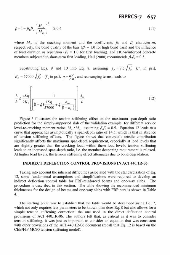
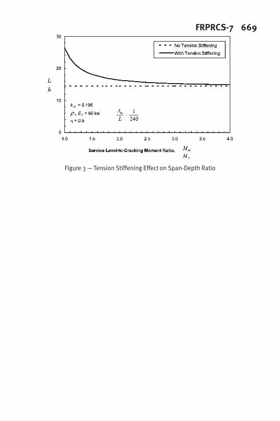
Figure 3 illustrates the tension stiffening effect on the maximum span-depth ratioprediction for the simply-supported slab of the validation example, for different servicelevel-to-cracking moment ratios, Mm / Mcr , assuming β1β2 = 0.5. Equation 12 leads to acurve that approaches asymptotically a span-depth ratio of 14.5, which is that in absenceof tension stiffening effects. The figure shows that concrete’s tensile contribution significantly affects the maximum span-depth requirement, especially at load levels thatare slightly greater than the cracking load; within these load levels, tension stiffening leads to an increased span-depth ratio, i.e. the member deepening requirement is relaxed. At higher load levels, the tension stiffening effect attenuates due to bond degradation.
INDIRECT DEFLECTION CONTROL PROVISIONS IN ACI 440.1R-06
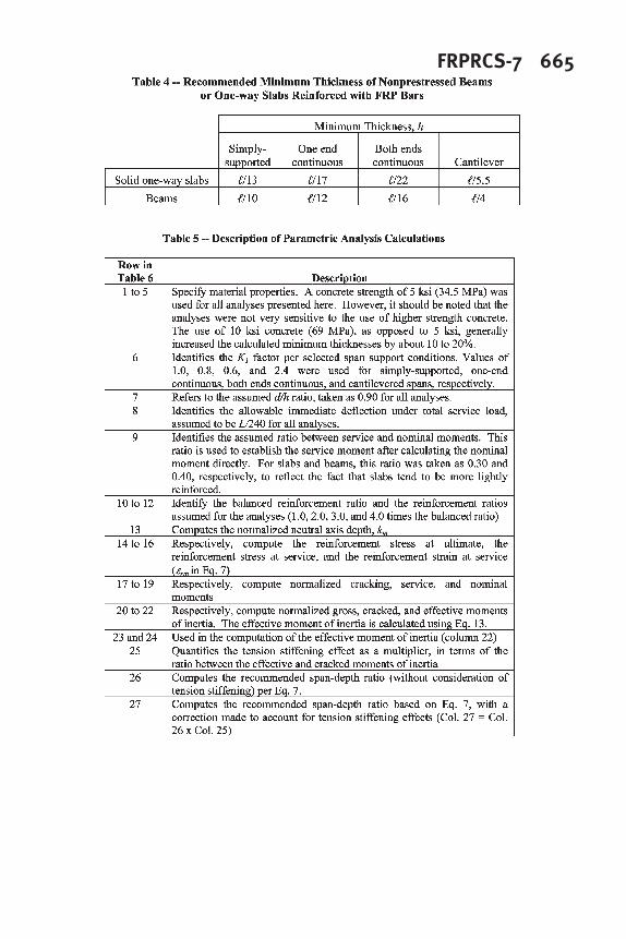
Taking into account the inherent difficulties associated with the standardization of Eq. 12, some fundamental assumptions and simplifications were required to develop an indirect deflection control table for FRP-reinforced beams and one-way slabs. The procedure is described in this section. The table showing the recommended minimum thicknesses for the design of beams and one-way slabs with FRP bars is shown in Table4.
The starting point was to establish that the table would be developed using Eq. 7,which not only requires less parameters to be known than does Eq. 8 but also allows for asimple tension stiffening correction: the one used in the direct deflection controlprovisions of ACI 440.1R-06. The authors felt that, as critical as it was to considertension stiffening, it was just as important to consider an equation that was consistent with other provisions of the ACI 440.1R-06 document (recall that Eq. 12 is based on the CEB/FIP MC90 tension stiffening model).
658 Ospina and GrossThe use of Eq. 7 in design is not straight forward because neither km nor εrm are known
prior to a detailed analysis. For this reason, it was decided to conduct a parametricanalysis based on typical conditions for FRP-reinforced concrete flexural members inorder to determine both km and ε rm. In the analyses, an arbitrary deflection-span limit of 1/240 (i.e. a maximum instantaneous deflection of L/240) was assumed under totalservice load. This value was not chosen to endorse a deflection limitation of L/240, butrather because of the relative consistency it provides with the span-depth limitationssuggested in ACI 318-05, as indicated by the results presented in Fig. 2. For simplicity, explicit modifications for time-dependent behavior and other factors were not applied in deriving the ACI 440.1R-06 table; however, such modifications can implicitly be addressed by adjusting the limiting deflection-span ratio to account for assumed time-dependent deflection multipliers and ratios of dead load to live load. The assumed deflection-span ratio is clearly stated in the text of ACI 440.1R-06 to provide the designerguidance when applying the table. Since the table is only intended for preliminary member sizing, the designer is permitted to adjust a suggested minimum thickness basedon less restrictive or more restrictive deflection-span limits.
Limiting span-depth ratios were first computed in the absence of tension stiffeningeffects, i.e. according to Eq. 7. Then, the tension stiffening effect was accounted for by multiplying the resulting span-depth ratios by the ratio of the effective moment of inertiato the cracked section moment of inertia, Ie/Icr, where Ie is calculated using the modified Branson’s equation for FRP, given in ACI 440.1R-06 as
gcr
a
cr
gd
a
cr
eII
M
M
I
M
M
I ≤
−+
=
33
1β (13)
where
1
5
1
≤
ρ
ρ
=β
bf
f
d (14)
In Eq. 14, ρf and ρ
bf are, respectively, the reinforcement ratio and the balanced
reinforcement ratio for an FRP-reinforced member.
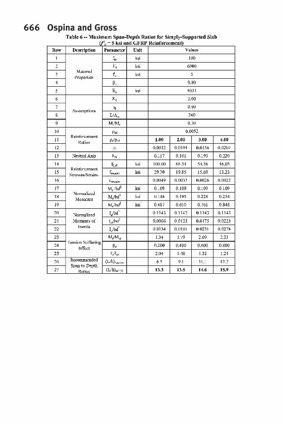
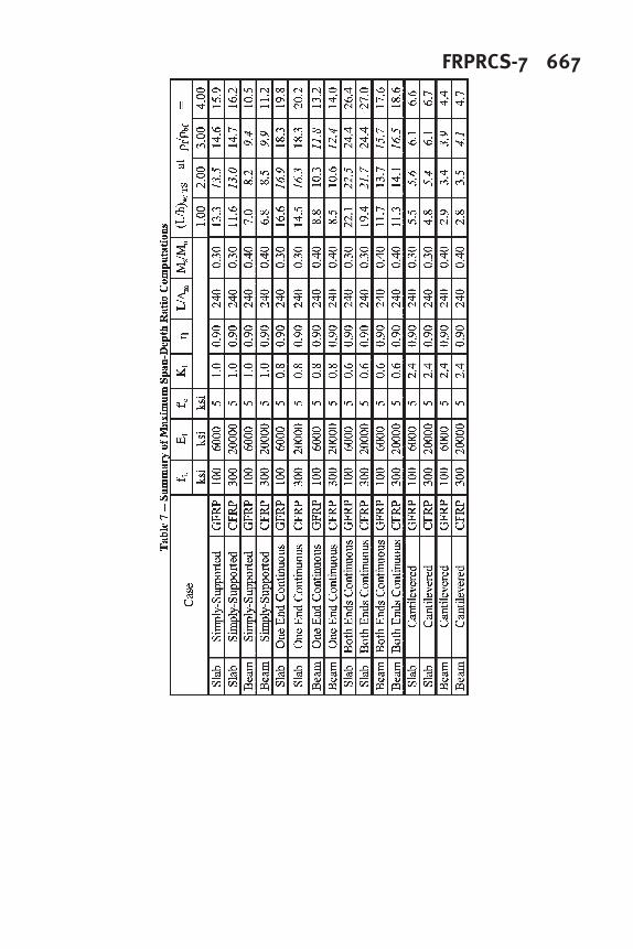
A description of the calculations performed in the analyses, including all fundamentalassumptions, are provided in Table 5, which facilitates interpretation of Table 6. The latter shows the results of a typical analysis, in this case for a simply-supported one-wayslab with 5 ksi (34.5 MPa) concrete and GFRP reinforcement. Numerous other tables were generated but were omitted due to space limitations.
Table 7 provides an overall summary of the analyses conducted, and forms the basis for the development of Table 4. Sixteen basic cases were considered, resulting from four different support conditions, two different reinforcement types (GFRP and CFRP), andtwo different member types (beam and slab). For each case, computations were performed considering four different reinforcement quantities, equivalent to 1.0, 2.0, 3.0,
FRPRCS-7 659and 4.0 times the balanced reinforcement ratio, respectively. For one-way slabs andbeams, the assumed ratio of service moment to calculated nominal moment was taken as 0.3 and 0.4, respectively. This difference is intended to reflect the fact that slabs, on arelative basis, tend to be more lightly loaded. Reinforcement properties for GFRP and CFRP reinforcement were assumed to represent typical values for commercially availablebars. As can be seen in Table 7, the type of FRP reinforcement does not have asignificant effect on the computed span-depth ratios. For this reason, the number of basiccases considered reduces to eight, with each case corresponding to a value in the final version of the ACI 440.1R-06 minimum thickness table.
Values from Table 7 chosen for inclusion in ACI 440.1R-06 Table 8.2 are indicated in italics. Span-depth ratios for one-way slabs are based on the analyses of sections reinforced at 2.0 times the balanced reinforcement ratio whereas those for beamscorrespond to analyses of sections reinforced at 3.0 times the balanced reinforcementratio. These choices reflect the general differences in reinforcing levels for beams and slabs. While it can be argued that lower reinforcement ratios are reasonable for designsin many cases, the data shows no significant difference in the computed values between, for example, the cases of 1.0 and 2.0 times the balanced reinforcement ratio.
CONCLUSIONS AND RECOMMENDATIONS
Defining a maximum span-depth ratio as a vehicle for indirect control of deflectionsin concrete beams and one-way slabs reinforced with FRP bars is affected by FRP’sstiffness, brittle-elastic nature, and bond properties. To overcome the limitations imposedby the influence of many intervening variables on the deflection calculations, a general indirect deflection control model for FRP-reinforced beams and one-way slabs is proposed. The model can be applied to a wide variety of support conditions regardless of the type of reinforcement. The procedure is also independent of the member’s effectivemoment of inertia, which is difficult to quantify across the cracked stage, and it is expressed in terms of an allowable deflection-span ratio, which allows designers to havefull control of the serviceability design depending on applicable deflection limits.
According to the proposed method, the maximum span-depth ratio in concrete beams or one-way slabs with FRP reinforcement is particularly affected by the level of FRPstrain at a crack at service load level. For comparable span lengths, concrete beams andone-way slabs with FRP need be deepened to satisfy the same maximum deflection-span ratios for steel-reinforced members. If concrete’s tension stiffening effect is accounted for, the member deepening penalty can be relaxed, especially at load levels that are roughly greater than that at first flexural cracking.
A series of indirect deflection control parametric analyses were performed on beamsand one-way slabs reinforced with FRP bars based on the proposed model. Concrete’stension stiffening effect was accounted for through some simplifications. Based on theseresults, the maximum span-depth ratios reported in Table 4 are proposed. This table was adopted by ACI 440 for inclusion in ACI 440.1R-06. The table is intended only for use in the preliminary sizing of members, and does not supersede the requirement fordesigners to check deflections directly, as stipulated by ACI 440.1R-06.
660 Ospina and GrossExperimental evidence studying deflections in FRP-reinforced concrete beams and
one-way slabs under uniformly distributed gravity loads for different support conditions is needed to further examine the quality of the proposed deflection control procedures.
ACKNOWLEDGMENTS
The authors would like to thank Dr. Scott D. B. Alexander for his comments indiscussions held on the subject of indirect deflection control of reinforced concrete flexural members.
REFERENCES
ACI Committee 435, “Allowable Deflections”, ACI Journal, Proceedings V. 65, No. 6,
1968, pp. 433-444.
ACI Committee 435, “State-of-the-Art Report, Deflection of Two Way Reinforced
Concrete Floor Systems,” ACI SP 43-3, Deflections of Concrete Structures, 1974, pp. 55-
81.
ACI Committee 435, “Proposed Revisions by Committee 435 to ACI Building Code and
Commentary Provisions on Deflections,” ACI Journal, Proceedings V. 75, No. 6, 1978,
pp. 229-238.
ACI Committee 440, "Guide for the Design and Construction of Concrete Reinforced
with FRP Bars,” ACI 440.1R-06, American Concrete Institute, Farmington Hills.
Branson, D.E., Deformation of Concrete Structures, McGraw-Hill, New York, 1977, 546
pp.
Comité Euro-International du Béton (CEB) / Fédération Internationale de la Précontrainte
(FIP), Model Code for Concrete Structures, MC-90, CEB, Thomas Telford House, 1990,
London.
Gao, D., Benmokrane, B., and Masmoudi, R., “A Calculating Method of Flexural
Properties of FRP-reinforced Concrete Beam: Part 1: Crack Width and Deflection,”
Technical Report, Department of Civil Engineering, Université de Sherbrooke, Québec,
1998, 24 pp.
Hall T., "Deflections of Concrete Members Reinforced with Fibre Reinforced Polymer
(FRP) Bars," M.Sc. Thesis, Department of Civil Engineering, The University of Calgary,
Calgary, Canada, 2000, 292 pp.
Ospina, C.E., Alexander, S.D.B., and Cheng, J.J.R., “Behaviour of Concrete Slabs with
Fibre-reinforced Polymer Reinforcement,” Structural Engineering Report No. 242,
Department of Civil and Environmental Engineering, University of Alberta, Edmonton,
Canada, 2001, 356 pp.
FRPRCS-7 661Yost, J.R., Gross, S.P., and Dinehart, D.W., “Effective Moment of Inertia for GFRP
Reinforced Concrete Beams,” ACI Structural Journal, Vol. 100, No. 6, Nov.-Dec. 2003,
pp. 732-739.
LIST OF SYMBOLS
d Effective flexural slab or beam depth
Ec Elastic modulus of concrete, ksi (MPa)
Ef Elastic modulus of FRP bars, ksi (MPa)
fr Concrete's modulus of rupture, ksi (MPa)
f’c Specified cylinder compressive strength of concrete, ksi (MPa)
h Slab thickness or beam depth
Icr
Cracked moment of inertia
Ie Effective moment of inertia
km Ratio of neutral axis-to-flexural depth at midspan, for cracked-elastic conditions
K1 Constant depending on boundary conditions
L ,ℓ Span length
Ma Applied moment
Mcr
Cracking moment
Mm Midspan moment
Mo Statical moment
n Modular ratio
β1
Bond coefficient in CEB/FIP MC90
β2
Performance coefficient in CEB/FIP MC90
∆m
Midspan deflection
εrm
Reinforcement strain at midspan
ρbf
Balanced reinforcement ratio for FRP reinforced member in ACI 440.1R-06
ρf Reinforcement ratio for FRP reinforced member in ACI 440.1R-06
ρr Reinforcement ratio
ψm
Midspan curvature
ψ1
Curvature at uncracked section level in CEB/FIP MC90
ψ2
Curvature at fully cracked section level in CEB/FIP MC90
ξ
Tension stiffening factor in CEB/FIP MC 90
662 Ospina and GrossAppendix A -- ACI 440.1R-06 Indirect Deflection Control Design Provisions
8.3.2.1 Recommended minimum thicknesses for design—Recommended minimum thicknesses for design of one-way slabs and beams are provided in Table 8.2. The table is only intended to provide guidance for initial design, and use of these recommended minimum thicknesses does not guarantee that all deflection considerations will be satisfied for a particular project. Table 8.2 – Recommended minimum thickness of nonprestressed beams or one-way
slabs
Minimum Thickness, h
Simply-
supported
One end
continuous
Both ends
continuous Cantilever
Solid one-way
slabs ℓ/13 ℓ/17 ℓ/22 ℓ/5.5
Beams ℓ/10 ℓ/12 ℓ/16 ℓ/4
Values in Table 8.2 are based on a generic maximum span-to-depth ratio limitation (Ospina, Alexander, and Cheng 2001) corresponding to the limiting curvature associated with a target deflection-span ratio (Eq. 8-10). The procedure can be applied for any type of reinforcement.
max1
1
5
48
−
≤
l
l ∆
ε
η
f
k
Kh
(8-10)
In Eq. (8-10), η = d/h, k is as defined in Eq. (8-12), and (∆/ℓ)
max is the limiting
service load deflection-span ratio. K1 is a parameter that accounts for boundary
conditions. It may be taken as 1.0, 0.8, 0.6, and 2.4 for uniformly loaded simply-supported, one-end continuous, both ends continuous, and cantilevered spans, respectively. The term εf is the strain in the FRP reinforcement under service loads, evaluated at midspan except for cantilevered spans. For cantilevers, εf shall be evaluated at the support. Eq. (8-10) assumes no tension stiffening. To consider the effects of tension stiffening in developing Table 8.2, the values resulting from Eq (8-10) were modified by the ratio of effective and fully cracked moments of inertia, computed using Eq. (8-13a) and (8-11), respectively. Tabulated values are based on an assumed service deflection limit of l/240 under total service load, and assumed reinforcement ratios of 2.0ρbf and 3.0ρbf for slabs and beams, respectively.
FRPRCS-7 663
664 Ospina and Gross
FRPRCS-7 665
666 Ospina and Gross
FRPRCS-7 667
668 Ospina and Gross
Figure 1 — Effect of Reinforcement Strain on Span-Depth Ratio
Figure 2 — Effect of Reinforcement Strain on Span-Depth Ratio
FRPRCS-7 669
Figure 3 — Tension Stiffening Effect on Span-Depth Ratio

670 Ospina and Gross


![ÏÑÇÓÉ ÊÒÇíÏ ÇáÓåæã Ýí ÇáÌíÒÇä ÇáÎÑÓÇäíÉ ÇáãÓáÍÉ … file130 :. (deflections): - - -1.... -2. ( ). (Long-Term deflection) ACI 435R-95.( ) [2]](https://img.pdfslide.us/doc/110x75/5aab8f9d7f8b9ac55c8c08d1/-deflections-1-2-long-term-deflection-aci-435r-95-.jpg)


![LATTICE DISCRETE PARTICLE MODELING OF SHEAR FAILURE IN ... · this end, ACI 440.1R-15 [3], provides guidance to estimate the nominal shear strength of GFRP RC beams under the assumption](https://img.pdfslide.us/doc/110x75/5e7990a6623aaf67f63aa08a/lattice-discrete-particle-modeling-of-shear-failure-in-this-end-aci-4401r-15.jpg)