Embed Size (px)
Citation preview

ACCEPTED MANUSCRIPT
Title: Flexural behaviour of concrete slabs reinforced with FRP bars in experiments and
according to aci ACI 440.1R guide
Author: Marcin Abramski, Piotr Korzeniowski, Witold Tisler
To appear in: Technical Sciences
Received 20 April 2016;
Accepted 11 November 2016;
Available online 21 November 2016.
This is a PDF file of an unedited manuscript that has been accepted for publication. As a service
to our customers we are providing this early version of the manuscript. The manuscript will
undergo copyediting, typesetting, and review of the resulting proof before it is published in its
final form. Please note that during the production process errors may be discovered which could
affect the content, and all legal disclaimers that apply to the journal pertain.
FLEXURAL BEHAVIOUR OF CONCRETE SLABS REINFORCED
WITH FRP BARS IN EXPERIMENTS AND ACCORDING TO ACI
440.1R GUIDE
Marcin Abramski1, Piotr Korzeniowski2, Witold Tisler3,
1Department of Rail Transportation and Bridges
2Department of Concrete Structures
3Department of Geotechnics, Geology and Marine Civil Engineering
Faculty of Civil and Environmental Engineering
Gdansk University of Technology
ul. Narutowicza 11/12, 80-233 Gdansk, Poland
Abstract
The paper presents research conducted on two concrete slabs reinforced with the carbon composite bars
and two other concrete slabs reinforced with basalt composite bars. The carbon bars were plain, while the basalt
ones were ribbed. The slabs were experimentally investigated in the flexural state of effort with the concentrated
forces applied. The results are compared with the analytical solution proposed in the guide ACI 440.1R-06 of the
American Concrete Institute. The calculation procedures in respect of flexure, as well as deflection, as per ACI
440.1R-06, are presented, briefly explained and discussed in the paper. Some suggestions to revise the existing
procedures are offered. The authors present and discuss the following results of their experimental investigation:
the ultimate capacity of the slabs, their modes of failure, deflections and the strains in reinforcement.
Keywords
basalt fibres, carbon fibres, FRP reinforcement, reinforcement bar, concrete slab, experiment
1. Introduction
Using Fibre Reinforced Polymer (FRP) materials in concrete structures may be
profitable for its durability. Apart from the high corrosion resistance there are other important
advantages of FRP materials: magnetic neutrality and high tensile strength. Unfortunately, FRP
have also its disadvantages in comparison to steel such as the fragility or the low elastic modulus
which is (with the exception of carbon FRP) much lower than for steel. Moreover the FRP
materials are not ductile at all: they do not yield but are elastic until the destruction. FRP
materials are also anisotropic: they are strong to tension only in one direction. The behaviour
1 corresponding author, e-mail: [email protected]
of concrete reinforced with FRP reinforcement bars is different from a traditionally (i.e. with
steel bars) reinforced structure. Application of this technology in construction requires from
engineers a broadened knowledge on calculating load-carrying capacity of structures reinforced
with FRP bars. This knowledge should be based on existing design standards.
The article presents research conducted on two concrete slabs reinforced with carbon
composite bars and two other concrete slabs reinforced with basalt composite bars. The slabs
were experimentally investigated in the flexural state of effort with concentrated forces applied.
One of the objectives of the experiments was to compare the behaviour of the slabs
reinforced with the polymer bars made from the different fibres (basalt and carbon). The prices
of the FRP bars are about seven times higher for the carbon composite than for the basalt
composite. The authors preferred the ribbed bars as the reinforcement for the examined slabs.
However the ribbed rods made from the carbon fibres were not available at the time.
Consequently, the ribbed basalt bars and the plane carbon bars had to be used for the
experiments.
The second objective was to compare the experimental load bearing capacity of the
tested slabs with the analytical solution proposed in a guide (ACI 2006) of the American
Concrete Institute.
2. State of the art
Flexural behaviour of concrete slabs reinforced with FRP bars is a very popular issue in
recent years (Salakawy E., Kassem C. 2003), (GangaRao et al. 2007). An intense research is
carried out in China and Japan (Salakawy E., Kassem C. 2003) and in Europe (Ospina & Nanni
2007), (El-Ghandour, A.W. et al. 2003). Experiments from the last few years show that FRP
reinforcement bars have under some specific circumstances more advantages than traditional
steel (Salakawy E., Kassem C. 2003).
As it is reported in the literature using FRP reinforcement instead of steel usually
increases load capacity of a concrete slab. That is caused mainly due to high tensile strength of
the FRP reinforcement. This fact is a very important argument for applying the alternative type
of reinforcement. Using the same amount of reinforcement a higher flexural strength (even up
to 100%) can be obtained (Salakawy E., Kassem C. 2003). However, numerous differences
between steel and FRP materials must be taken into account. Linear-elastic behaviour of FRP
until failure, low ductility and lower elastic modulus than steel (with the exception of the carbon
FRP) cause that load-carrying capacity of the concrete slab differs substantially. Concrete slab
reinforced with steel bars usually achieves yield strength before rupture and failure is not rapid.

Concrete slab reinforced with FRP bars are characterized by a different destruction mode:
usually concrete crushing or rarely reinforcement rupture. The both failure modes are rapid.
The basalt FRP are an interesting alternative for the better known and wider spread
carbon or glass FRP. In addition to good mechanical properties, basalt has a high chemical and
thermal stability, good thermal insulating, electrical and sound properties. Basalt fibres are also
significantly better chemically resistant than glass fibres, particularly in a strongly alkaline
environment. For example, corrosive liquids and gases can be transported with pipes made of
basalt composite (Urbański M. et al 2013), (Van de Velde et al 2002).
The authors of the paper decided to program their experimental research based on the
Guide for the Design and Construction of Structural Concrete Reinforced with FRP Bars (ACI
2006) published by the American Concrete Institute. Computations of a cross section strength
according to that document should be based on the following assumptions:
perfect bond exists between concrete and FRP reinforcement,
the tensile behaviour of the FRP reinforcement is linearly elastic until failure,
the tensile strength of concrete is ignored,
the maximum usable compressive strain in the concrete is assumed to be 0,003,
strain in the concrete and in the FRP reinforcement is proportional to the distance from the
neutral axis.
3. Calculation procedures proposed by ACI 440.1R-06
3.1. Flexure
The strength design philosophy states that the design flexural capacity nM must
exceed the factored acting bending moment uM :
n uM M (1)
where: nM - nominal moment capacity,
uM - factored moment at section,
- strength reduction factor
The design flexural strength is calculated as nominal flexural strength nM multiplied
by a strength reduction factor . The nominal flexural strength is determined based on strain
compatibility, internal force equilibrium and the controlled mode of failure.
In the beginning of the procedure a mode of failure has to be determined. A
reinforcement ratio (Eq-2) has to be assumed and compared to the balanced reinforcement ratio

(Eq-3). Comparison of these two values determine the failure mode. As it was mentioned above,
FRP reinforcement does not yield, so balanced ratio is computed using design tensile strength:
f
f
A
b d
(2)
1
'0,85
f cucfb
fu f cu fu
Ef
f E f
(3)
where: f - FRP reinforcement ratio,
fA - area of FRP reinforcement,
b - width of rectangular section,
d - distance from extreme compression fiber to centroid of tension reinforcement,
fb - FRP reinforcement ratio producing balanced strain conditions,
1 - factor reducing the real depth of the section, taken as 0,85 for concrete strength
'cf up to and including 4000 psi (28 MPa)
'cf - specified compressive strength of concrete,
fuf - design tensile strength of FRP, considering reductions for service environment
fE - design modulus of elasticity of FRP
cu - ultimate strain in concrete
If the balanced ratio is bigger than reinforcement ratio (𝜌𝑓𝑏 > 𝜌𝑓), the concrete crushing
must be obtained. Otherwise, reinforcement rupture governs. In the following paragraph the
case of concrete crushing is considered.
Based on the equilibrium of forces and strain compatibility (Fig. 1), it can be written as
follows:
2
n f f
aM A f d
(4)
0,85 '
f f
c
A fa
f b
(5)
1f f cu
d af E
a
(6)
where: ff - stress in FRP reinforcement in tension,
a - depth of equivalent rectangular stress block, equal 1 c
Substituting value “a” from equation (5) into equation (6), it can be obtained:
2
1
( ) '0,85 0,5
4
f cu cf f cu f cu fu
f
E ff E E f
(7)
Nominal flexural strength is defined above. The FRP reinforcement is linearly elastic
up to failure, so result of equation (7) must be less than fuf (design tensile strength). This model
of failure (concrete crushing) is recommended to design.
If f fb the failure mode is reinforcement rupture and maximum strain in concrete
(0,003) may not be attained. The calculation procedure is other than for concrete crushing
failure mode. Analysis has two unknown values: compressive strain c in concrete at failure
and the depth to neutral axis c . Nominal flexural strength can be computed using equation (8):
1
2n f fu
cM A f d
(8)
where: c - distance from extreme compression fibre to the neutral axis
For a given section the product of 1 c in equation above depends on material properties and
FRP reinforcement ratio. The maximum value is obtained when maximum concrete strain
(0,003) is attained. A simplified calculation of nominal strength is based on these two equations:
1
2
bn f fu
cM A f d
(9)
cu
b
cu fu
c d
(10)
where: bc - distance from extreme compression fibre to centroid of tension reinforcement,
fu - design rupture strain of FRP reinforcement
Because FRP bars are not characterized by a ductile behaviour, a strength reduction
factor must be used to provide a higher reserve of strength in a designed structural member.
The strength reduction factor ∅ for compression controlled failure is 0,65 in recommendation
(ACI 2006). The member constructed for concrete crushing may not fail accordingly. For
instance, if the concrete strength is higher than specified, a member failure mode may be a FRP
rupture. This is the main reason for creating a relationship between two values of factor ∅. A
section controlled by a concrete crushing is defined as a section in which 𝜌𝑓 > 1,4 ∙ 𝜌𝑓𝑏 and a
section with FRP rupture is defined by 𝜌𝑓 > 𝜌𝑓𝑏. Strength reduction factor can be computed
using equation (11):
0,55
0,3 0,25 1,4
0,65 1,4
f fb
f
fb f fb
fb
f fb
for
for
for
(11)
A relation between strength reduction factor and reinforcement ratio is presented on
fig. 2. There is a linear transition between factors 0,55 and 0,65.
If a member is designed to fail by FRP rupture, a minimum amount of reinforcement
should be obtained ( n crM M ). Provisions are based on ACI 318-14 (American Concrete
Institute 2014). To compute a minimal amount of reinforcement eq. (12) can be used.
,min
4,9 ' 330c
f w w
fu fu
fA b d b d
f f
(12)
where: ,minfA - minimum area of FRP reinforcement needed to prevent a failure of flexural
member upon cracking,
wb - width of the web.
If a failure mode is concrete crushing (𝜌𝑓𝑏 > 𝜌𝑓) the minimum amount of reinforcement
is automatically achieved. Therefore, eq. (12) can be used only if failure mode is controlled by
FRP rupture.
3.2. Deflection
Calculating the short term deflection in the ACI Report (ACI 2006) is based on the
effective moment of inertia. Taking into consideration the differences in stiffness and bond
characteristic between steel and FRP, an effective moment of inertia is computed using the
following equation:
3 3
1cr cre g d cr g
a a
M MI I I I
M M
(13)
where: eI - effective moment of inertia,
d - reduction coefficient used in calculating deflection,
crM and aM - cracking and applied moment, respectively,
crI and gI - cracked and gross moment of inertia of concrete section, respectively.

The most important factor in this equation is 𝛽𝑑 which reduces the stiffness of FRP bars.
In the next to last revision of ACI (ACI 2003) this coefficient was based on the proportion of
the FRP and steel elastic moduli:
0,5 1FRPd
s
E
E
(14)
where FRPE - modulus of elasticity of FRP.
However effective moment of inertia eI calculated with use of the equations (13) and
(14) resulted in obtaining too low values of deflection. Therefore coefficient d required some
new considerations. The newer evaluation of FRP RC test data, based on (Yost et al. 2003),
leads to the following proposal:
1
15
f
d
fb
(15)
Based on the value of effective moment of inertia a deflection of a simply supported beam can
be computed using the following equation:
25
48 c e
M l
E I
(16)
where: - deflection due to sustained loads,
M - maximum bending moment,
l - span length,
cE - modulus of elasticity of concrete
Analysing the two d approaches two values of deflection can be obtained, one with
coefficient used in the previous guide (ACI 2003) and second - in the current one (ACI 2006).
The authors performed a comparative analysis of the both approaches (Table 1). Material
characteristics of concrete, amount of reinforcement and the applied moment (which was
assumed as equal to 20 kNm) are the same for all cases. Moduli of elasticity and ultimate tensile
strengths of reinforcement are taken from the report (ACI 2006).
4. Authors’ experimental investigation
Four slabs were experimentally investigated. Two slabs were reinforced with basalt FRP
bars and two other with carbon FRP bars. The slabs were 360 cm long x 90 cm wide x 8 cm
thick and had two spans, both 160 cm long (Fig. 3).
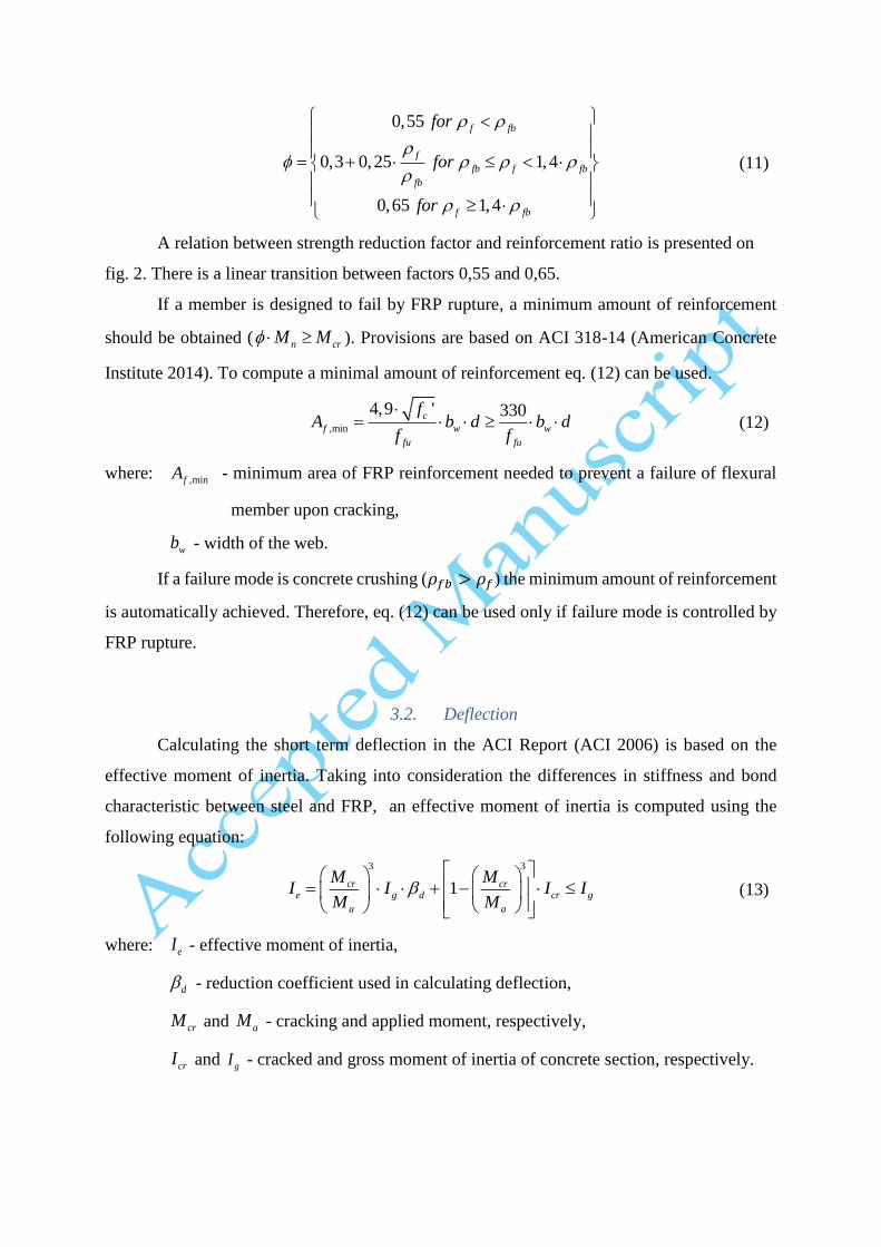
4.1. Test specimens and material properties
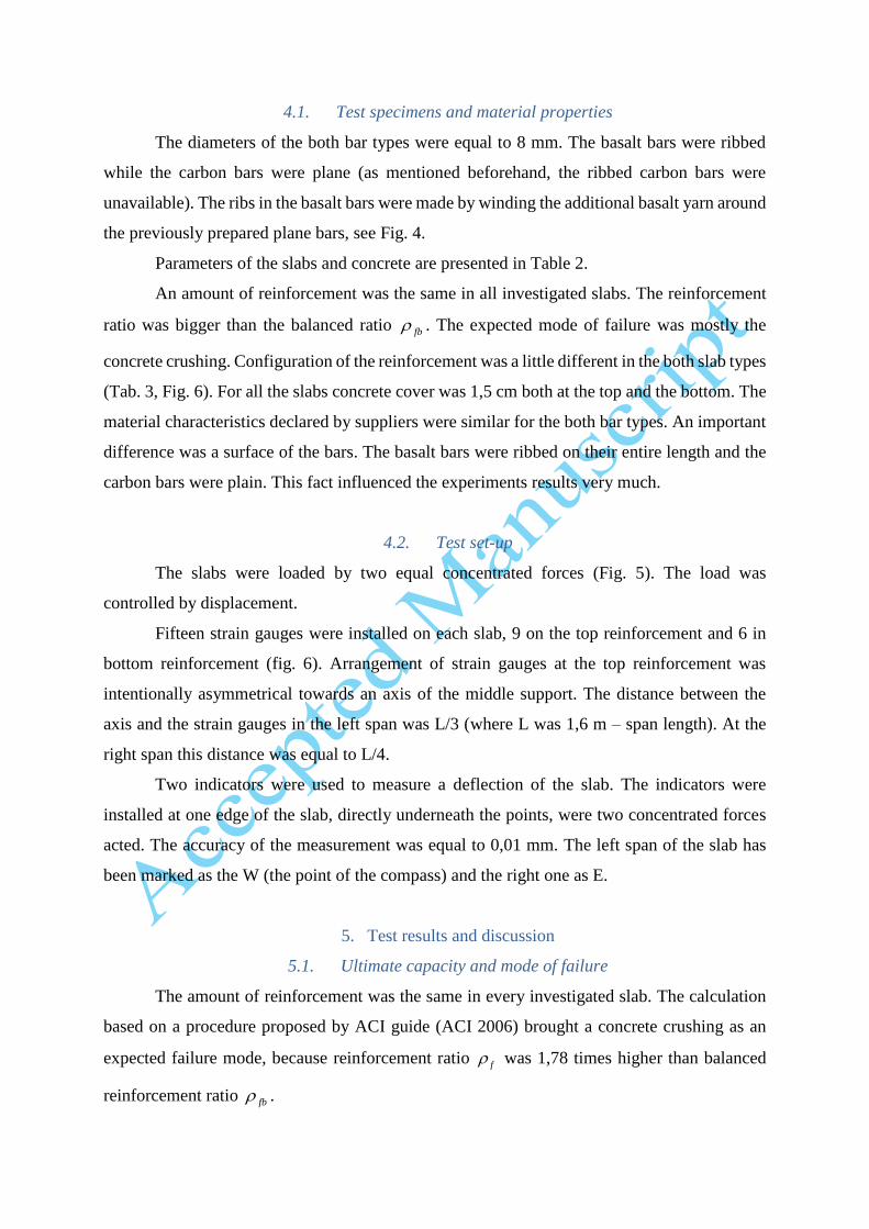
The diameters of the both bar types were equal to 8 mm. The basalt bars were ribbed
while the carbon bars were plane (as mentioned beforehand, the ribbed carbon bars were
unavailable). The ribs in the basalt bars were made by winding the additional basalt yarn around
the previously prepared plane bars, see Fig. 4.
Parameters of the slabs and concrete are presented in Table 2.
An amount of reinforcement was the same in all investigated slabs. The reinforcement
ratio was bigger than the balanced ratio fb . The expected mode of failure was mostly the
concrete crushing. Configuration of the reinforcement was a little different in the both slab types
(Tab. 3, Fig. 6). For all the slabs concrete cover was 1,5 cm both at the top and the bottom. The
material characteristics declared by suppliers were similar for the both bar types. An important
difference was a surface of the bars. The basalt bars were ribbed on their entire length and the
carbon bars were plain. This fact influenced the experiments results very much.
4.2. Test set-up
The slabs were loaded by two equal concentrated forces (Fig. 5). The load was
controlled by displacement.
Fifteen strain gauges were installed on each slab, 9 on the top reinforcement and 6 in
bottom reinforcement (fig. 6). Arrangement of strain gauges at the top reinforcement was
intentionally asymmetrical towards an axis of the middle support. The distance between the
axis and the strain gauges in the left span was L/3 (where L was 1,6 m – span length). At the
right span this distance was equal to L/4.
Two indicators were used to measure a deflection of the slab. The indicators were
installed at one edge of the slab, directly underneath the points, were two concentrated forces
acted. The accuracy of the measurement was equal to 0,01 mm. The left span of the slab has
been marked as the W (the point of the compass) and the right one as E.
5. Test results and discussion
5.1. Ultimate capacity and mode of failure
The amount of reinforcement was the same in every investigated slab. The calculation
based on a procedure proposed by ACI guide (ACI 2006) brought a concrete crushing as an
expected failure mode, because reinforcement ratio f was 1,78 times higher than balanced
reinforcement ratio fb .

In the case of the slabs reinforced with the basalt bars the failure mode was as expected,
the same as in the over-reinforced slabs with the steel reinforcement, see Fig 7.
Unexpectedly, the failure mode of slabs reinforced with carbon bars was definitely
different. The most probable reason for that was a weak bond between concrete and bars. As a
result, the obtained load-carrying capacities of the slabs C-1 and C-2 were significantly lower
than expected and reached 40% of the calculated value, i.e. 90 kN (see Table 4). Three splits
were formed: one in the symmetry axis of the elements and two under the point loads (Fig. 8).
All the splits developed before the destruction of the slabs. The reason for the premature failure
must have been slip of reinforcement bars in concrete. The carbon bars were plain, while the
basalt ones were ribbed. The slip hypothesis was confirmed by the behaviour of the longitudinal
reinforcement bars. They were not covered by concrete at the slab face and were visible on two
face surfaces of the slab before the test beginning. When the experiments were over, the bars
were visible too, but they were pulled about 1 cm into the slab (Fig. 9).
In the Table 4 the predicted values of load-carrying capacities of the tested slabs are
compared with the experimental results. The predicted values were computed based on the
calculation procedures presented in the chapter 3. The strength reduction factor ∅ was taken
into account according to the Equation (11). It is worth noting that in the case of the slabs
reinforced with the carbon plain bars the predicted load–bearing capacity is much overestimated
in comparison to the experimental one. Such a difference is not acceptable. In the case of the
slabs reinforced with the ribbed basalt bars the load–bearing capacity obtained from the
experiments is much lower than the theoretical value, but when the strength reduction factor ∅
is used, the consistency between experimental and theoretical load–bearing capacity is quite
good (does not exceed 17%).
The obtained difference in the load-carrying capacities of the both slab types was equal
up to 50% (fig. 10).
5.2. Deflection
The load versus deflection diagrams for all the tested slabs are presented in Fig. 11. The
deflection was taken as the mean value from the both spans. All the slabs reached deflection of
about 4 cm. The cracking bending moment was observed for all the slabs at the load level 15
kN.
The load-deflection curves obtained for the slabs reinforced with bars made of basalt
composite (B-1 and B-2) differ considerably from the curves obtained for the slabs reinforced
with bars made of carbon composite (C-1 and C-2). The first two curves are almost bilinear:
they consist of two almost straight sections: before cracking and after cracking up to failure. In
case of the slabs C-1 and C-2 the second section of the curve becomes flat shortly before
reaching the maximum load level. The reason of such a behaviour must be a slip of plain carbon
bars in concrete.
None of experimental curves coincide in the stage after cracking with a development of
deflection obtained analytically according to (ACI 2006). The deflections obtained analytically
are too small in comparison to experimental data. The reason of this inconsistency is factor d
(Eq. 15). According to the last version of the guidelines (ACI 2006) this factor depends on the
balanced reinforcement ratio fb . This ratio is influenced by the ultimate tensile strength fuf
(Eq. 3). It means that deflection could be different for elements which have the same stiffness
but different ultimate strength, which is incorrect. This remark was noticed already in (El-
Ghandour, A.W. et al. 2003) and was recommended to consider in the next revision of the
guidelines (ACI 2006).
According to the previous version of (ACI 2006) the factor d was computed according
to Eq. (14), which was giving much higher values. The application of that approach leads to
increasing effective moment of inertia eI and would in effect result in even lower deflections
that obtained from Eq. (15). It confirms, that the changes made in the last revision of the
guidelines (ACI 2006) were needed.
5.3. Strains in reinforcement
Figures 12 and 13 present strain development in the reinforcement bars under the
concentrated loads (fig. 12) and in the symmetry axis of the slab (fig. 13) versus the applied
load. The graphs made for the slabs with basalt reinforcement do not present the full range of
loading the slabs because of local damages of strain gauges. The damages occurred by strain
level of about 6‰.
If properly anchored, the both basalt and carbon bars would have been deformed
longitudinally to the same extent up to load level P=30 kN, as the deflection development up to
that load level was very similar for all the tested slabs (see fig. 11). However, the strain
development in carbon bars was slow in comparison to basalt bars. Therefore, the reinforcement
bars made of carbon composite were significantly less effective. In case of the slab C-2 the
lower effectiveness was observed since the cracking load (P=15 kN) up to failure (P=38 kN).
In case of the slab C1 it was observed also since the cracking load (P=15 kN) for the support

bars and since the load level about P=25 kN for the bars of the both spans. The strain
development presented in the both diagrams confirms the slip of carbon bars in concrete.
6. Conclusions
As mentioned beforehand the objective of the authors’ investigations was to compare
the behaviour of the concrete slabs reinforced with the basalt and carbon bars, whereas it turned
out that the crucial problem was not in the material of the fibres but in the bond between the
concrete and the polymer bars. Load-carrying capacity of slabs reinforced with ribbed bars is
definitely higher than capacity of slabs reinforced with plain ones, although the strength as well
as the modulus of the elasticity were higher for the plain carbon bars than for the ribbed basalt
ones. In the presented experimental investigation the difference was equal to 50%. The plain
bars (in the presented investigation made of a carbon composite) cannot be properly anchored
in concrete and are not effective in sustaining bending moments. The problem of the bond
between the concrete and the bar seems to be crucial when using the polymer bars as a
reinforcement of the concrete structures. The surface of the plain polymer bars should be made
rough, for instance by coating it with special adhesive and sand. The American guidelines (ACI
2006) address this problem just in an outline. Thus, the calculation procedures proposed by this
guide is not useful if a bond between FRP reinforcement and concrete is too weak, like in the
case of plain bars. In such a case the flexural failure mode differs much from the mode assumed
in the theory of reinforced concrete structures.
In case of slabs reinforced with ribbed bars (in the presented investigation made of a
basalt composite) the load-carrying capacity calculated according to (ACI 2006) is more
consistent with the experimental results. However, deflections obtained from the calculation
procedure underestimate the values obtained in the experiments. The problem was reported in
the literature (El-Ghandour, A.W. et al. 2003) and should be considered in the next revision of
the guidelines.
Acknowledgement
The research was co-financed by the European Union from the European Regional
Development Fund (85%) and by Polish Ministry of Regional Development (15%) as part of
operational programme “Innovative Economy”. The project was called "Innovative means and
effective methods to improve safety and durability of buildings and transport infrastructure in
a sustainable development strategy” and was run by Technical University of Lodz, Poland. The
authors of this paper carried out Task No. 018818. This support is greatly acknowledged.

References
ACI, 2003. Guide for the Design and Construction of Concrete Reinforced with FRP Bars.
ACI 440.1R-03,
ACI, 2006. Guide for the Design and Construction of Structural Concrete Reinforced with
FRP Bars. ACI 440.1R-06,
American Concrete Institute, 2014. Building code requirements for structural concrete and
commentary. ACI 318-14, p.525.
El-Ghandour, A.W., Pilakoutas, K. & Waldron, P., 2003. Punching Shear Behavior of FRP
RC Flat Slabs Part 1 : Experimental Study. Journal of Composites for Construction, 7
(3), pp.258–265.
GangaRao, H.V.S., Taly, N. & Vijay, P. V, 2007. Reinforced Concrete Design with FRP
Composites, Boca Raton, Florida, USA: CRC Press.
Ospina, C.E. & Nanni, A., 2007. Current FRP-reinforced concrete design trends in ACI 440.1
R. In Proceedings of the 8th International Symposium on Fiber Reinforced Polymer
Reinforcement for Concrete Structures - FRPRCS-8. Patras, Greece, pp. 14–6.
Salakawy E., Kassem C., B.B., 2003. Flexural behaviour of bridge deck slabs reinforced with
FRP composite bars. In Proc., 6th International Symposium on FRP Reinforcement for
Concrete Structures. Singapore. Singapore: World Scientific Publishing, pp. 1291–1300.
Urbański, M., Łapko, A. & Garbacz, A., 2013. Investigation on concrete beams reinforced
with basalt rebars as an effective alternative of conventional R/C structures. In 11th
International Conference on Modern Building Materials, Structures and Techniques.
Vilnius, Lithuania, pp. 1183-1191.
Van de Velde, K., Kiekens, P., Van Langenhove, L., Cater, S., 2002. Basalt fibers as
reinforcement for composites, Editorial, International Composites News, March 2002
Yost, J.R., Gross, S.P. & Dinehart, D.W., 2003. Effective Moment of Inertia for Glass Fiber-
Reinforced Polymer-Reinforced Concrete Beams. ACI Structural Journal, 100(6),
pp.732–739.

Fig. 1. Strain and stress distribution at ultimate conditions (ACI 2006)
Fig. 2. Strength reduction factor as a function of the reinforcement ratio (ACI 2006)
Fig. 3. Dimensions of the investigated slabs
Fig. 4. Detail of basalt FRP bars
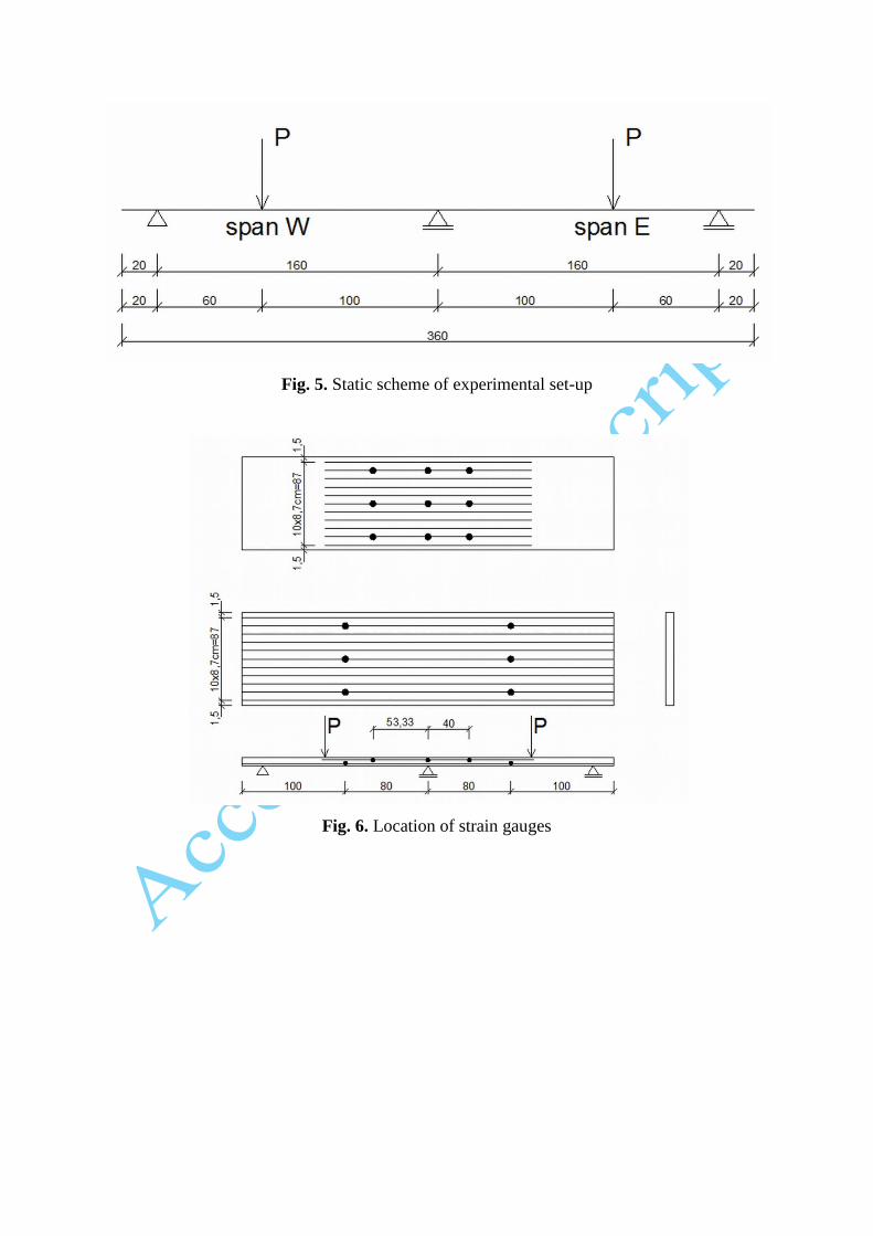
Fig. 5. Static scheme of experimental set-up
Fig. 6. Location of strain gauges
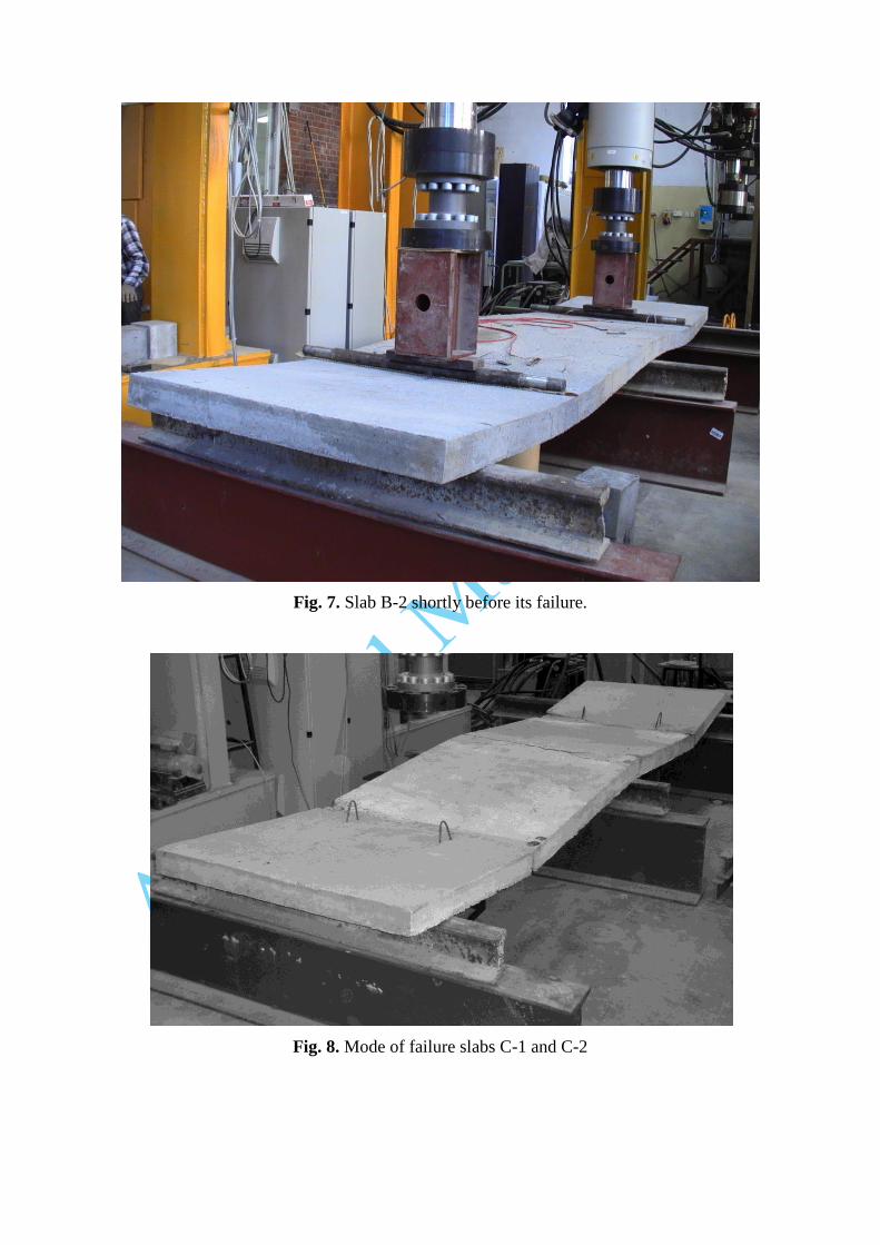
Fig. 7. Slab B-2 shortly before its failure.
Fig. 8. Mode of failure slabs C-1 and C-2

Fig. 9. Detail of slab C-2 after its failure
Fig. 10. Load-carrying capacities in [kN] of the tested slabs
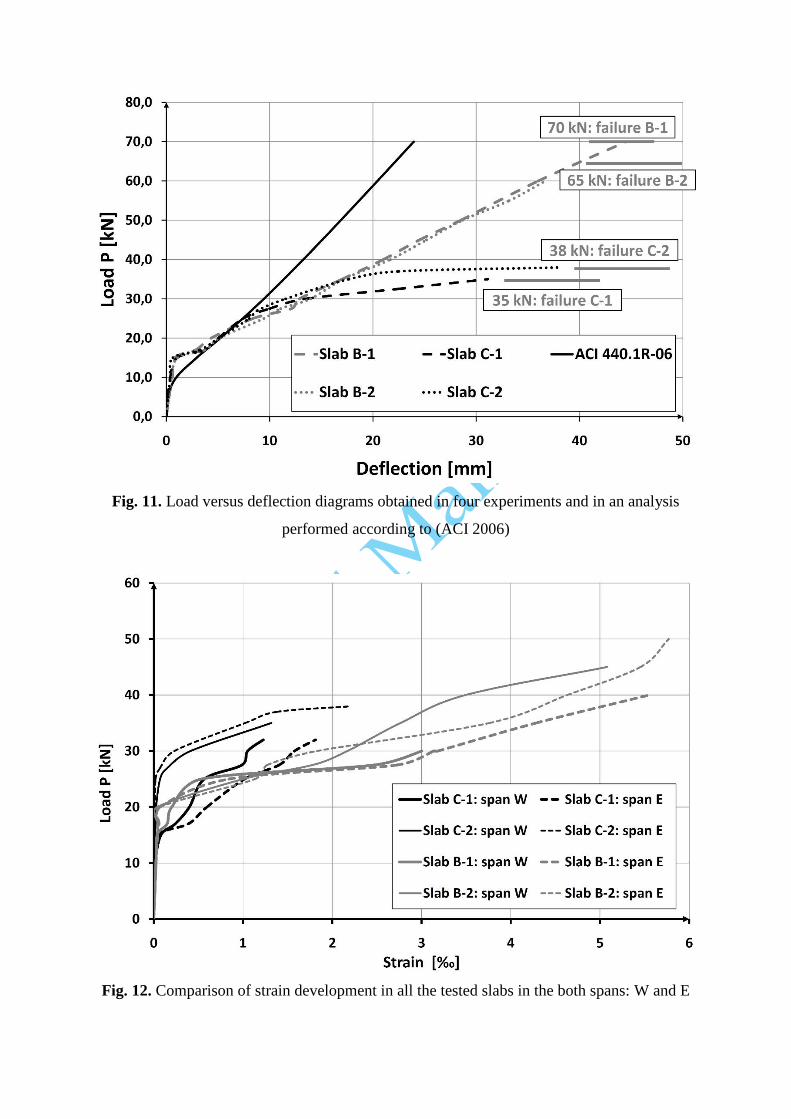
Fig. 11. Load versus deflection diagrams obtained in four experiments and in an analysis
performed according to (ACI 2006)
Fig. 12. Comparison of strain development in all the tested slabs in the both spans: W and E
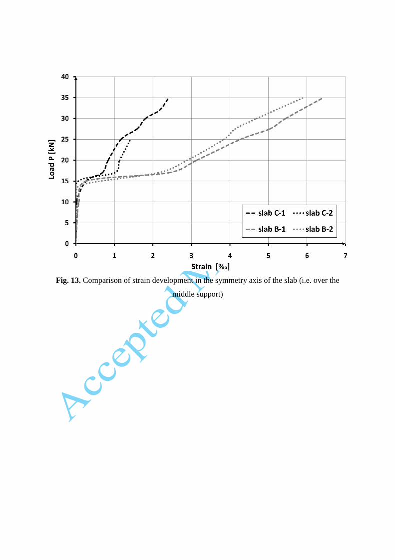
Fig. 13. Comparison of strain development in the symmetry axis of the slab (i.e. over the
middle support)
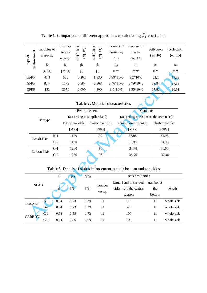
Table 1. Comparison of different approaches to calculating d coefficient
Table 2. Material characteristics
Bar type
Reinforcement
(according to supplier data)
Concrete
(according to results of the own tests)
tensile strength elastic modulus compressive strength elastic modulus
[MPa] [GPa] [MPa] [GPa]
Basalt FRP B-1 1100 90 37,88 34,98
B-2 1100 90 37,88 34,98
Carbon FRP C-1 1280 98 34,78 36,60
C-2 1280 98 35,70 37,40
Table 3. Details of slab reinforcement at their bottom and top sides
SLAB
ρf ρfb ρf/ρfb bars positioning
[%] [%] [%] number
on top
length [cm] in the both
sides from the central
support
number at
the
bottom
length
BASALT B-1 0,94 0,73 1,29 11 50 11 whole slab
B-2 0,94 0,73 1,29 11 40 11 whole slab
CARBON C-1 0,94 0,55 1,73 11 100 11 whole slab
C-2 0,94 0,56 1,69 11 100 11 whole slab
typ
e o
f
rein
forc
emen
t modulus of
elasticity
ultimate
tensile
strength coef
fici
ent
(eq
. 15
)
coef
fici
ent
(eq
. 14
)
moment of
inertia (eq.
13)
moment of
inertia
(eq. 13)
deflection
(eq. 16)
deflection
(eq. 16)
Ef ffu β1 β2 Ie1 Ie2 Δ1 Δ2
[GPa] [MPa] [-] [-] mm4 mm4 mm mm
GFRP 41,4 552 0,262 1,530 2,99*10^6 3,2*10^6 53,1 49,58
AFRP 82,7 1172 0,584 2,568 5,46*10^6 5,79*10^6 29,04 27,38
CFRP 152 2070 1,000 4,300 9,0*10^6 9,55*10^6 17,62 16,61

Table 4. Comparison of test results with code predictions
Type of
reinforcement
Experimental
failure load
Theoretical
flexural
capacity
Experimental/
Theoretical
Experimental/
Theoretical with strength
reduction factor (0,65)
Mode
of
failure [kN] [kN] [-] [-]
BASALT B-1 70 91,46 0,765 1,17 CC
B-2 65 91,46 0,71 1,10 CC
CARBON C-1 35 89,36 0,39 0,60 SF
C-2 38 90,86 0,42 0,64 SF
Note: CC – failure obtained by the concrete crushing;
SF – failure obtained by the reinforcement slip in concrete.


![Full-scale testing and numerical analysis of a precast ... · concrete is available in ACI 440.1R-15 [30]. Bischoff [31] provided a comparison among different methodologies used to](https://img.pdfslide.us/doc/110x75/5e7990a6623aaf67f63aa089/full-scale-testing-and-numerical-analysis-of-a-precast-concrete-is-available.jpg)